Article

Reducing the Power Consumption of the Electrodynamic Suspension Levitation System by Changing the Span of the Horizontal Magnet in the Halbach Array

1
Faculty of Electrical Engineering, Warsaw University of Technology, 75, Koszykowa St., 00-662 Warszawa, Poland
2
Hyper Poland Electro S.A, 03-828 Warszawa, Poland
3
Faculty of Transport, Warsaw University of Technology, 75, Koszykowa St., 00-662 Warszawa, Poland
*
Author to whom correspondence should be addressed.
Energies 2021, 14(20), 6549; https://doi.org/10.3390/en14206549
Submission received: 22 September 2021 / Revised: 8 October 2021 / Accepted: 11 October 2021 / Published: 12 October 2021

Abstract

:
In high-speed magnetic railways, it is necessary to create the forces that lift the train. This effect is achieved by using active (EMS) or passive (EDS) magnetic systems. In a passive system, suspension systems with permanent magnets arranged in a Halbach array can be used. In this paper, an original Halbach array with various alternately arranged horizontally and vertically magnetized magnets is proposed. Correctly selected geometry allows us to obtain higher values of levitation forces and lower braking forces in relation to a system with identical horizontally and vertically magnetized elements. The effect of such a shape of the magnetic arrangement is the reduction of instantaneous power consumption while traveling due to the occurrence of lower braking forces. In order to perform a comparative analysis of the various geometries of the Halbach array, a simulation model was developed in the ANSYS Maxwell program. The performed calculations made it possible to determine the optimal dimensions of horizontally and vertically magnetized elements. The results of calculations of instantaneous power savings for various cruising speeds are also included.

1. Introduction

Most existing magnetically levitated trains use electromagnetic levitation systems (EMS). Such an arrangement involves equipping the vehicle with power-supplied electromagnets attracting to the ferromagnetic track [1,2,3]. However, there is also an electrodynamic type of levitation, where a vehicle equipped with a magnetic field source repels from the electrically conductive track [1,4,5]. Electrodynamic suspension (EDS) systems may be based on permanent magnets arranged in a Halbach array and are perfect for application in high-speed magnetically levitating trains (maglevs [6,7] and hyperloops [8,9]) because of their construction simplicity and linearly increasing lift-to-drag ratio with velocity. However, at relatively low speeds (below 300 km/h) electrodynamic systems such as Inductrack generate high drag forces when compared with a classic nonmagnetic high-speed railway [10,11,12]. Several solutions of EDS systems that generate low drag force have been proposed, such as null flux systems [13,14] or a ladder-type Inductrack [15,16]. In both of those systems, the reduction of drag force comes from the optimization of the conducting track geometry. Both systems have excellent lift-to-drag ratios at low speeds; however, at the same time, they have a very poor lift-to-weight ratio.
The levitation and drag forces in EDS systems occur as an effect of permanent magnets moving along the conductive plate [17,18,19,20]. Since the distribution of eddy current flow in the plate depends on the magnetic induction in the air gap, both the levitation and the drag forces of an EDS system are closely related to the waveform of the source field from permanent magnets arrangement. Previously published papers described the influence of PMs’ geometry on the shape of the magnetic induction in the air gap. In [21], the width-to-length ratio of the Halbach array is optimized to achieve an EDS system with low drag forces. In [22], the shape of permanent magnets is optimized so that the Halbach array consists of trapezoidal magnets in the cross-section. On the other hand, in [23], a Halbach array was developed, consisting of two smaller arrays differing in a span of a horizontally magnetized magnet. In [24,25], non-symmetrical Halbach arrays with wide vertically magnetized PM magnets are described. The authors mainly consider forces with a vertical component.
In this paper, a Halbach array with a different span of horizontally magnetized permanent magnets is investigated for application in a low-power EDS system. It means that some of the permanent magnets are wider than the others in the array. Such non-symmetrical arrangement may be characterized by lower drag forces and higher lift forces, which leads to a higher lift-to-drag ratio and lift-to-weight ratio as a result. We compare the required power delivered to the vehicle to overcome the forces of magnetic drag for considered Halbach arrays. Apart from these parameters, the magnetic induction waveforms are compared for several arrangements.

2. Analytical Methods

The classic Halbach array consists of evenly long magnets in cross-section and its peak magnetic field at the surface is described as [26]
B 0 = B r ( 1 e k h m ) sin ( π M ) π M
where Br is PM’s remanence, hm is PM’s thickness, M is the number of permanent magnets per wavelength of the Halbach array and k is calculated as
k = 2 π λ
where λ is a magnetic wavelength. Based on Equation (1), we can calculate two components of the magnetic field created by a classic Halbach array:
B x = B 0 sin ( k x ) e k g
B y = B 0 cos ( k x ) e k g
where x is displacement along the Halbach array and g is transverse displacement from Halbach array surface.
In this paper, all the considered Halbach arrays are the same wavelength λ but have a different span of a horizontally magnetized permanent magnet. In Figure 1, there is an example of Halbach array with a narrow horizontally magnetized permanent magnet.
Based on the descriptions in Figure 1, Equation (5) introduces the factor of filling the wavelength with a horizontally magnetized permanent magnet.
γ h m = l h m l v m + l h m = l h m 0.5 λ
where lhm is the length of the horizontally magnetized PM and lvm is the length of the vertically magnetized PM.
A series of parametric transient simulations were conducted in Ansys Maxwell 3D. Simulations were parametrized with the horizontal magnet fill factor γhm. The geometrical, material and dynamic parameters used in the simulations are described in Table 1. At first, we used a magnetostatic solver, which allowed us to calculate the waveforms of magnetic induction in the air gap for three different cases of fill factor. Second, we used a transient solver. The analysis investigated a Halbach array magnets arrangement moving along an aluminum plate. The virtual forces were read from the whole permanent magnets’ set. The Halbach array consisted of 4 wavelengths in order to reduce the end effects. The simulations were conducted for six different velocities of the PM array to observe the skin-effect.

3. Results

3.1. Magnetic Field Waveform

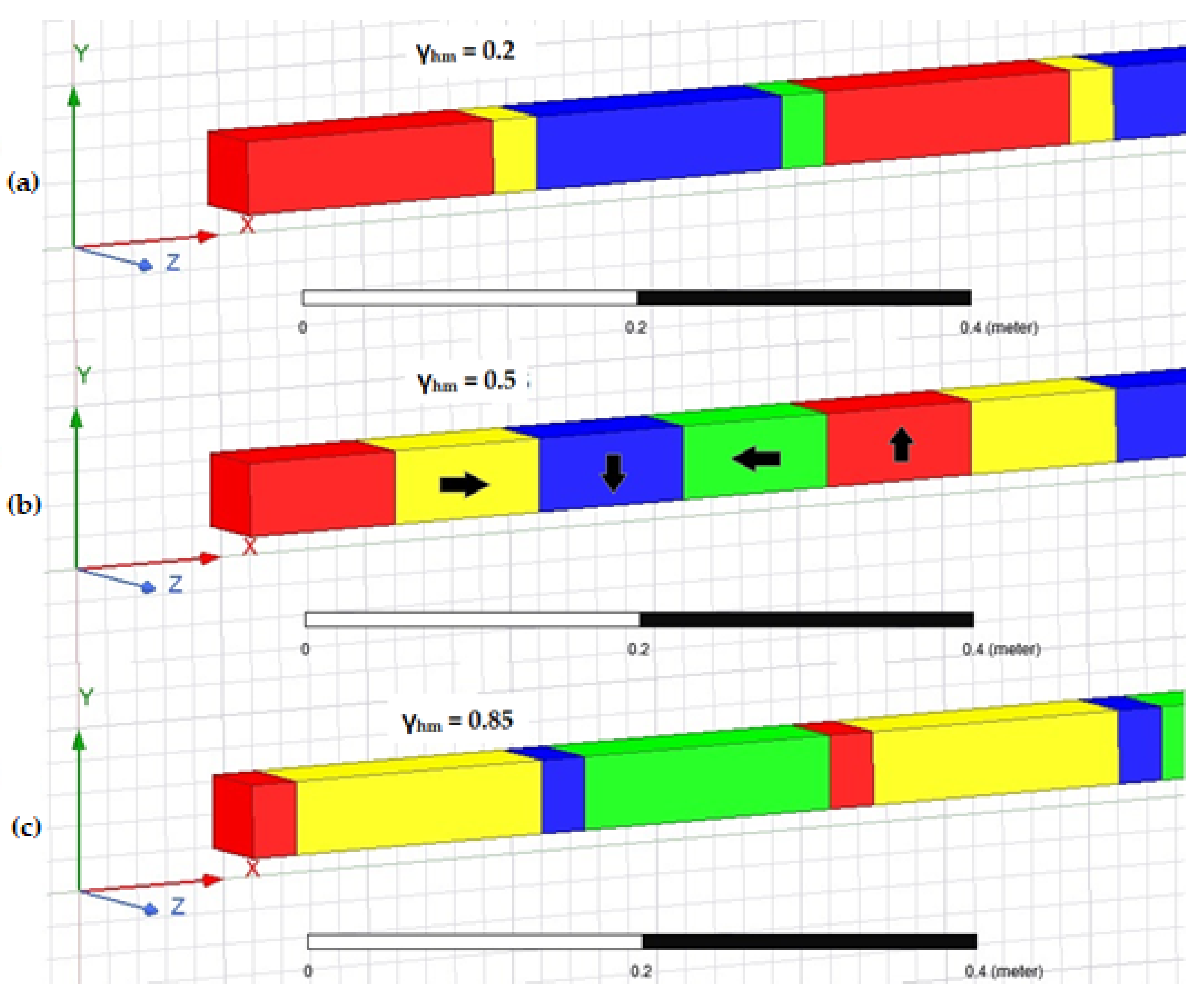
A series of parametrized 2D magnetostatic simulations allowed us to obtain the magnetic field under the Halbach array with different Halbach array fill factors. The three most important cases are depicted in Figure 2, with γhm = 0.2, 0.5 and 0.85. A fill factor of 0.2 means that only 20% of the wavelength λ is filled with horizontally magnetized PM, while 0.5 refers to a classic Halbach array. The cases where fill factors are equal to 0.2 and 0.85 are significant, because, for these values, the power consumption reaches the local minimum, which is shown later in the paper. Yellow and green blocks correspond to horizontally magnetized permanent magnets, while red and blue blocks correspond to vertically magnetized permanent magnets.
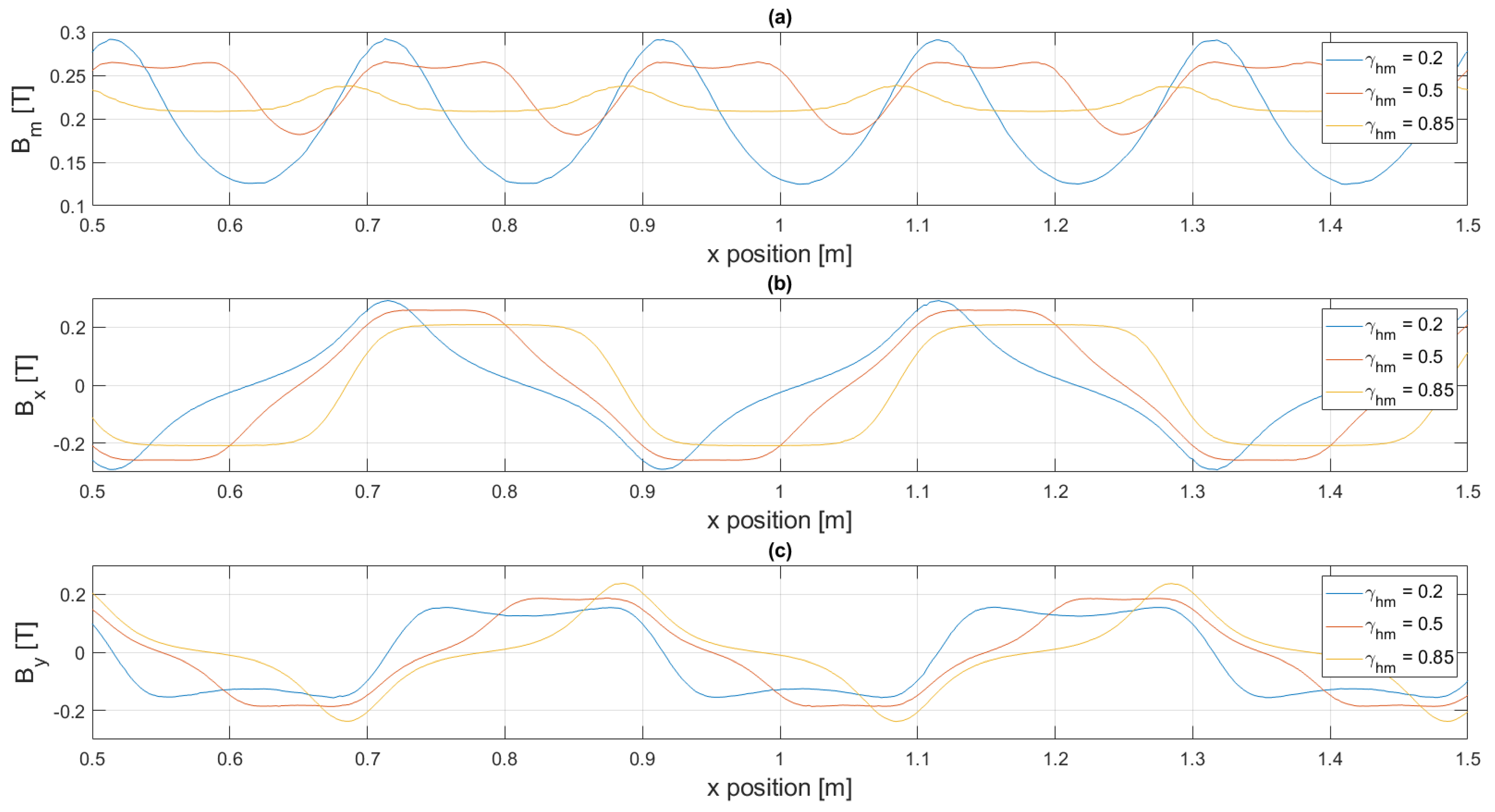
For each fill factor case, we calculated its magnetic field waveform beneath the array. Then, each of the waveform was decomposed into its x and y components. In Figure 3a, the chart depicts a section of the magnitude of the magnetic induction; Figure 3b depicts a section of the x component of the field and Figure 3c depicts a section of the y component of the field. Those quantities are related to each other:
B m = B x 2 + B y 2
The magnetic field was measured in the airgap, 30 mm beneath Halbach arrays. This was calculated on the basis of Equation (7), which describes an optimal wavelength λ for a Halbach array moving at a certain height above the plate [3].
λ o p t i m u m = 4 π g
On the basis of Figure 3, it can be noticed that the Halbach with fill factor γhm = 0.2 creates a magnetic field; the Bx component is triangular, narrow and has the highest peak value, while the distribution of the By component is trapezoidal with the lowest maximum value. In the Halbach array with γhm = 0.85, the components have opposite waveforms. The Bx waveform is trapezoidal, while the By component is triangular and has the highest peak value. The average values of the magnetic field magnitudes Bm are calculated in Table 2. The classic Halbach array with γhm = 0.5 has the highest average value, while the arrangement with low horizontally magnetized PM γhm = 0.2 has the lowest value.

3.2. Transient Simulation Results

We conducted 250 transient simulations in 3D Ansys Maxwell. The Halbach array described in Table 1 moved at different velocities above an aluminum plate. For the simulations, we chose velocities between 2 and 100 m/s and fill factor values between 0.05 and 0.95. The simulation steps were condensed in the areas of characteristic values (e.g., at low velocities where a maximum value of the braking force or of fill factors occurs, indicating low power consumption). For each simulation case, the length of the conducting plate was calculated, equal to four lengths of the magnetic packet, to obtain stabilized force values for each of the simulated cases. Based on the length of the packet travel path and its considered velocity, the simulation time was calculated and given in the analysis setup. In the simulation, we used an adaptive mesh offered by the Ansys software limited to the maximum number of elements equal to 250,000. Increasing the mesh further did not give more accurate results but only extended the simulation time.
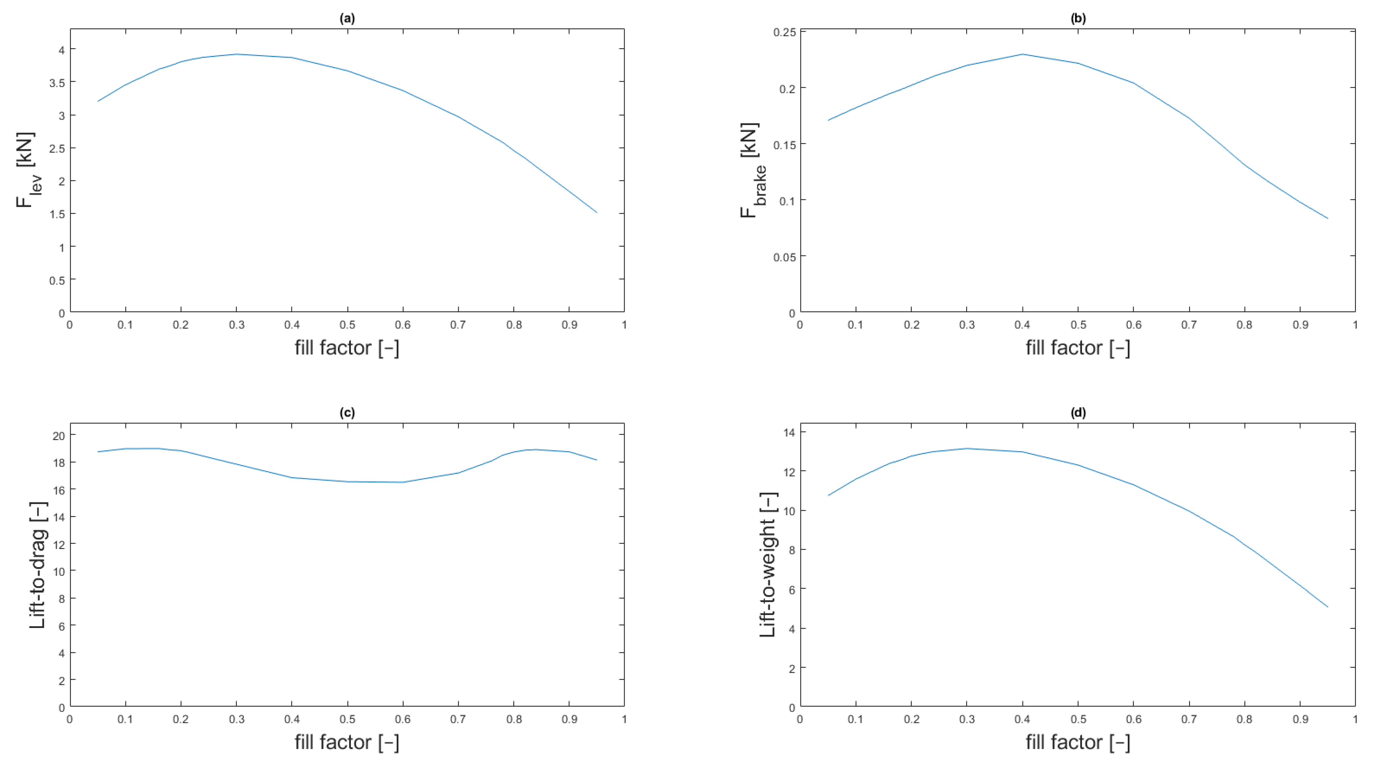
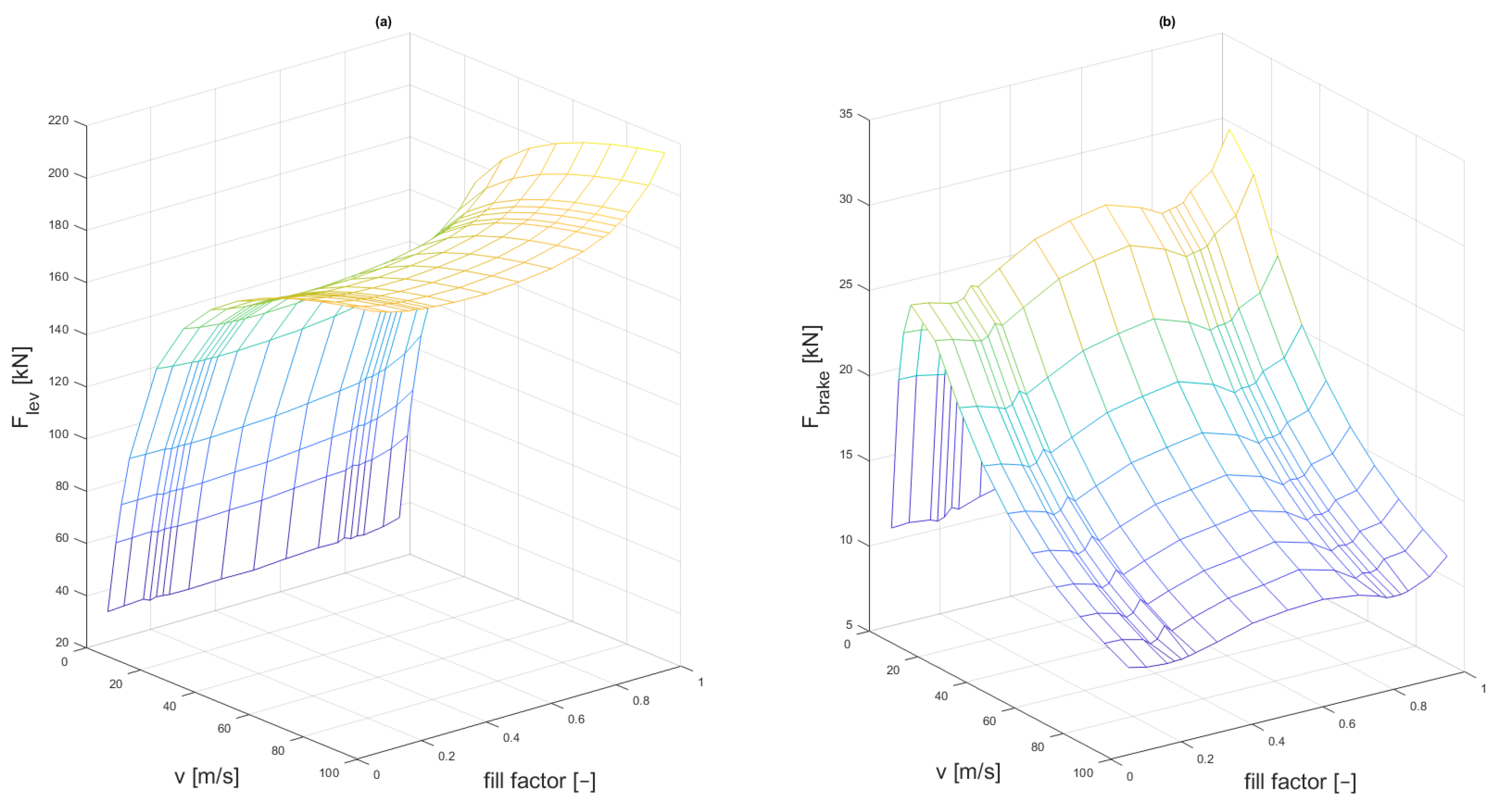
The levitation and braking forces were obtained. Then, the lift-to-drag and lift-to-weight ratios were calculated. The results are shown in Figure 4. Since the general shape of the curves does not change with velocity, in Figure 5, there are same quantities pictured only for the maximal velocity vmax = 100 m/s.
In Figure 4 and Figure 5, the characteristics are highly non-linear along the fill factor. The levitation force (Figure 5a) is the greatest when the fill factor γhm = 0.3, while the braking force (Figure 5b) is the lowest when γhm = 0.9. That means that the most effective, in terms of the mass of the PMs, is the arrangement with a fill factor of 0.3 and the arrangement causing lowest drag forces is the one with a fill factor of 0.9. To compare the cases in terms of power consumption, we conducted further analyses.

3.3. Calculation of the Required Levitation Force

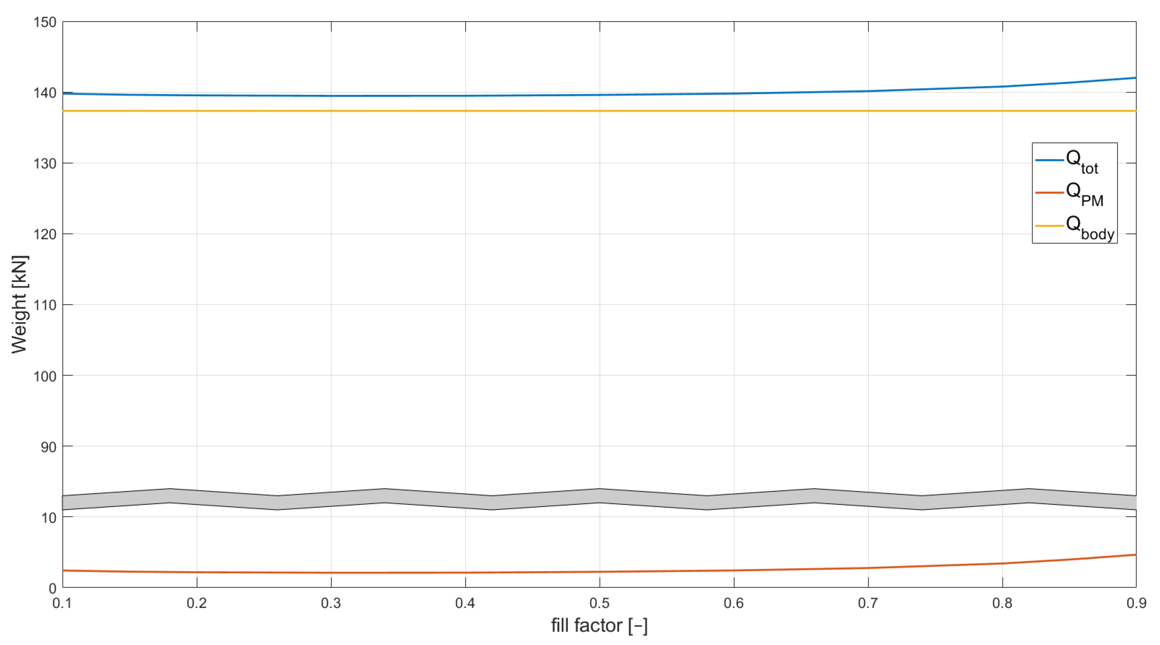
The results pictured above were scaled so that the levitation system would be able to levitate a maglev vehicle the mass of which is described in Table 2 as mbody = 14,000 kg. The system was designed to begin the levitation at velocity vlew = 10 m/s. This means that, at this velocity, the created levitation force is equal to the total weight of the vehicle Qtot, which consists of the body car weight Qbody and the levitation magnets weight QPM, as in
Q t o t = Q b o d y + Q P M
While the body car weight is constant, the Halbach arrangement weight is variable, is analogous to the lift-to-weight ratio and depends on the fill factor. In actual application, this results in a variable length of the Halbach arrangement (generated forces increase in proportion to the array length). The size of the packet cross-section remains constant. Based on Figure 5, an array with γhm = 0.9 creates the lowest levitation force, so the permanent magnet mass is higher than the mass of an array with γhm = 0.3, which creates the highest levitation force. The permanent magnets mass for a given fill factor can be calculated with
L W r a t i o = Q b o d y + Q P M Q P M
Q P M = Q b o d y L W r a t i o 1
Based on Equations (9) and (10), we calculated the required levitation force, which is equal to Qtot. The results are shown in Figure 6.
The 3D charts from Figure 4 were rescaled, so that the permanent magnets arrangements were able to levitate the whole vehicle at a velocity of 10 m/s. The two main characteristics are shown in Figure 7.

3.4. Power Consumption Analysis

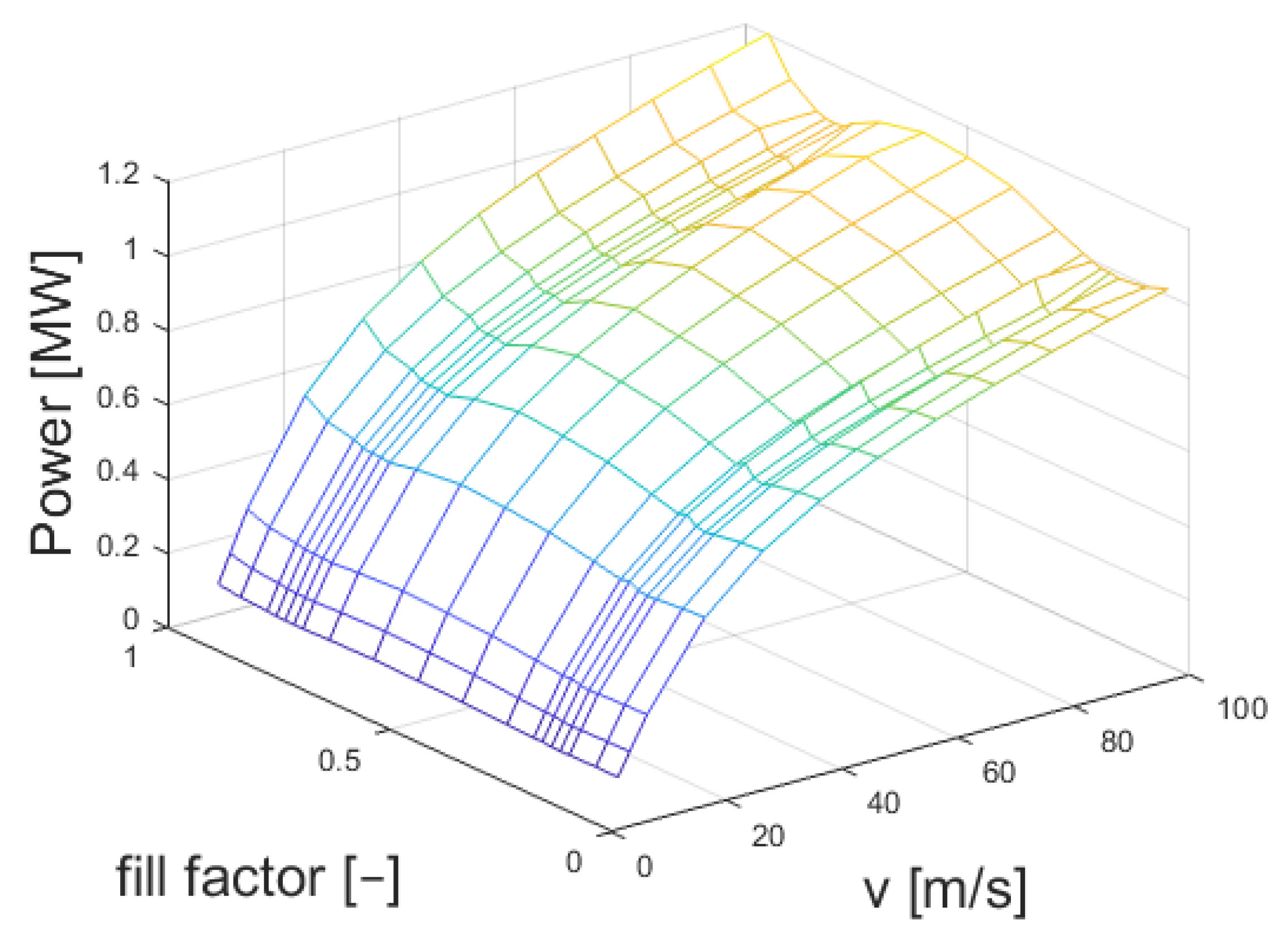
On the basis of the results presented in Figure 7, we calculated the instantaneous power needed to overcome the magnetic braking force, as in Equation (11). As seen in the above figure, the force of magnetic braking is not only variable due to different velocities of travel but also due to the fill factor value.
P = v F b r a k e
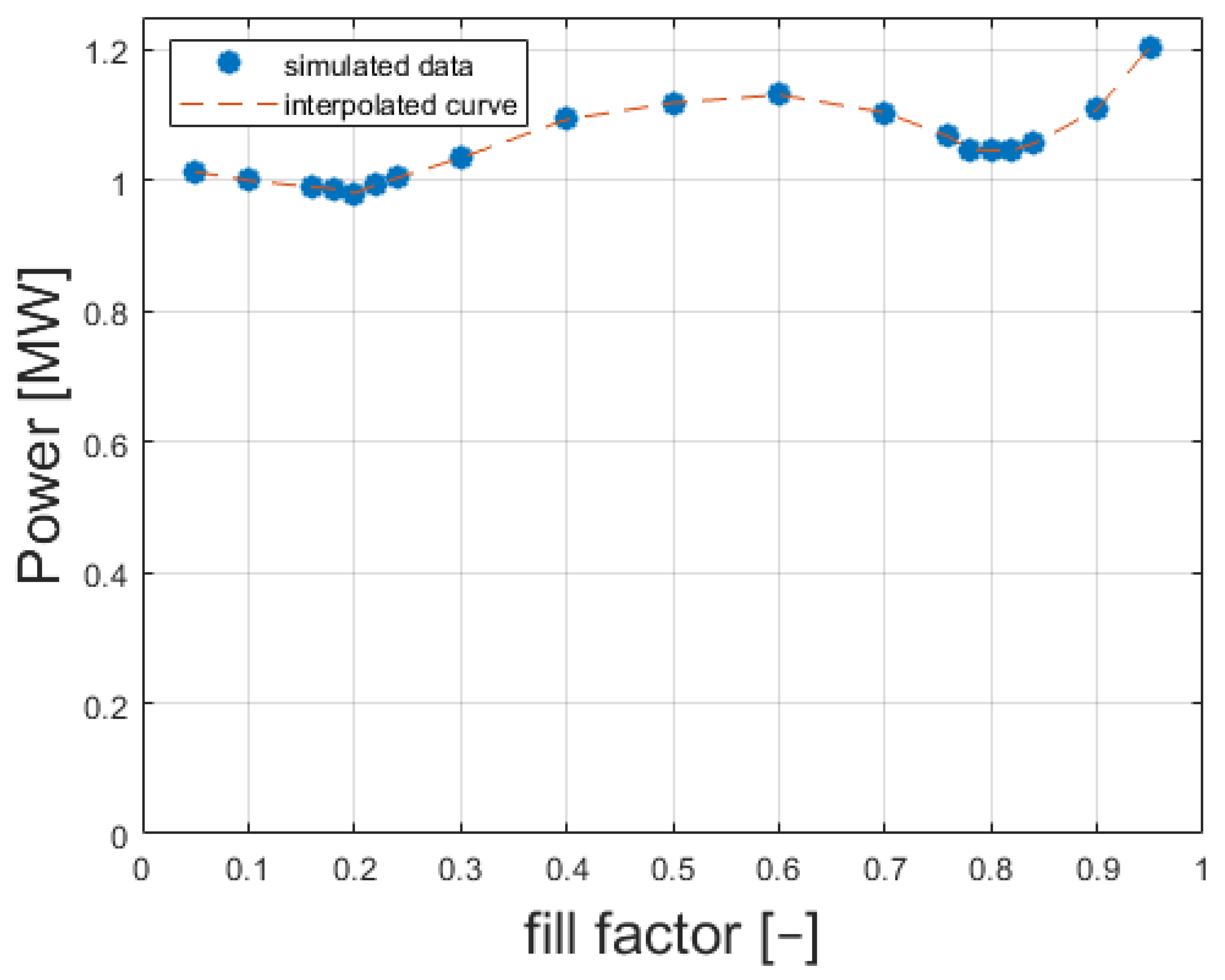
Figure 8 depicts the instantaneous power required to overcome magnetic braking forces according to Equation (11). The figure depicts the value of power for the velocities from 0 to 100 m/s and for fill factors from 0.05 to 0.95. In Figure 9, the characteristics show the power required to overcome magnetic braking forces for velocity = 100 m/s. According to Figure 8 and Figure 9, a properly selected fill factor plays a significant role when the vehicle is traveling at high speed. At velocity v = 100 m/s, the required power at fill factor γhm = 0.5 is 1.15 times higher than that at γhm = 0.2. When it comes to absolute values, the power saving for the case under consideration equals to more than 0.156 MW, as it is shown in Table 3.
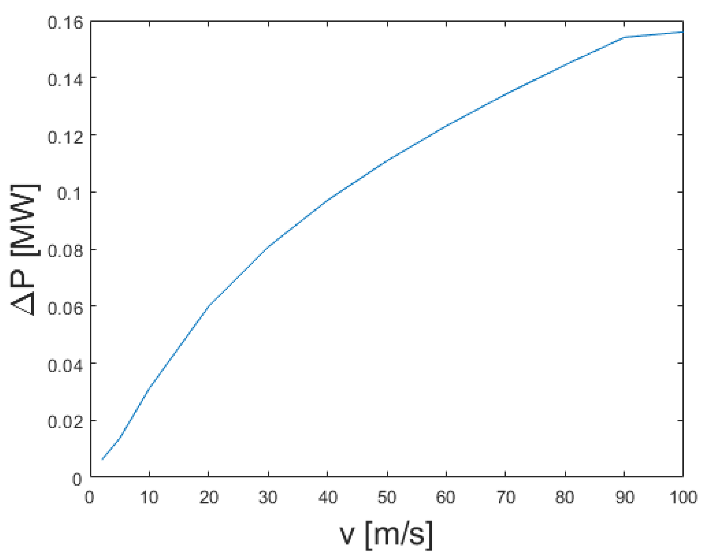
According to Figure 8, for every considered velocity, the PM arrangement with fill factor = 0.2 has the lowest required power. Figure 10 depicts the difference of the required power for permanent magnet arrangements with fill factor = 0.5 and with fill factor = 0.2 as a function of velocity. The difference is calculated as
Δ P = P γ h m = 0.5 P γ h m = 0.2  
On the basis of the results from Figure 10, it can be seen that, for every velocity, the PM Halbach array with fill factor = 0.5 generates more braking forces than the arrangement with fill factor = 0.2, which, in effect, turns out to be the one that allows us to obtain the most energy-saving scenario.

4. General Discussions

Selecting the appropriate fill factor makes it possible to design a more energy-efficient levitation system than when the classic Halbach array (γhm = 0.5) is used. Here, we show that, for the system described in Table 1 (with the γhm = 0.2), the power savings at velocity = 100 m/s can even reach 15% and the higher the velocity, the greater the percentage of power-saving. The fill factor described in this paper is the best for a given EDS system. For other geometries of the magnetic suspension system, the value of the best fill factor may slightly differ.
It should also be mentioned that the simulation results are characterized by a certain inaccuracy of calculations related to the density of the computational mesh. An element particularly susceptible to numerical errors is the PM Halbach array, where multiple magnetization direction changes occur in a single arrangement. In the simulation, a specific density of the computational mesh was determined. It was decided not to increase the mesh size so as not to increase the computation time unnecessarily. The average distance between computational nodes in the simulation was equal to 0.01 m. Considering the geometric parameters of the Halbach array given in Table 1, this could cause an error of 5% in the calculation results. When researching the fill factor generating the lowest power-dragging forces, the accuracy of numerical calculations should be considered. In this case, it should be assumed that the value of the best fill factor was selected with an accuracy error of 5%.

5. Conclusions

This paper presents a method to obtain for power savings in passive magnetic levitation systems of high-speed magnetic railways. The method relies on designing a Halbach array with a different fill factor of a horizontal magnet, compared the classic arrangement, where vertical and horizontal magnets have equal sizes (γhm = 0.5). Such an approach changes the waveform of magnetic induction in the airgap and, as a result, changes the forces created by the traveling PM array. Although the overall volume (and mass) of the PM arrangement may remain constant, selecting the appropriate γhm factor allows researchers to design a better power-saving levitation system capable of carrying the weight of the traveling high-speed magnetic railway. We conducted a series of numerical computations with the usage of Ansys Maxwell. Based on the simulation results, further calculations were made. It was calculated that the arrangement generating the lowest instantaneous power is the Halbach array with fill factor γhm = 0.2 for each considered velocity. This value was determined with an accuracy error of 5%.

Author Contributions

Conceptualization, T.K., L.G.; methodology, T.K., L.G.; software, T.K.; validation, T.K.; formal analysis, L.G., P.R.; investigation, T.K., Ł.O.; resources, P.R.; data curation, T.K.; writing—original draft preparation, T.K.; writing—review and editing, T.K., L.G., P.R., M.N., Ł.O.; visualization, T.K.; supervision, L.G.; project administration, T.K.; funding acquisition, L.G. All authors have read and agreed to the published version of the manuscript.

Funding

Not applicable.

Institutional Review Board Statement

Not applicable.

Informed Consent Statement

Not applicable.

Data Availability Statement

Not applicable.

Conflicts of Interest

The authors declare no conflict of interest.

References

  1. Han, H.-S.; Kim, D.-S. Magnetic Levitation; Springer: Dordrecht, The Netherlands, 2016. [Google Scholar] [CrossRef]
  2. Bohn, G.; Steinmetz, G. The electromagnetic levitation and guidance technology of the ’transrapid’ test facility Emsland. IEEE Trans. Magn. 1984, 20, 1666–1671. [Google Scholar] [CrossRef]
  3. Park, D.-Y.; Gieras, J.F. Incheon Airport Maglev Line. Prz. Elektrotechniczny 2019, 1–3. [Google Scholar] [CrossRef]
  4. Powell, J.R.; Danby, G. MAGLEV Technology Development. In Transportation Technologies for Sustainability; Ehsani, M., Wang, F.Y., Brosch, G.L., Eds.; Springer: New York, NY, USA, 2013. [Google Scholar] [CrossRef]
  5. Lee, H.-W.; Kim, K.-C.; Lee, J. Review of maglev train technologies. IEEE Trans. Magn. 2006, 42, 1917–1925. [Google Scholar] [CrossRef]
  6. Gurol, S.; Baldi, R.; Bever, D.; Post, R. Status of The General Atomics Low Speed Urban Maglev Technology Development Program. In Proceedings of the 18th International Conference on Magnetically Levitated Systems and Linear Drives, Shanghai, China, 26–28 October 2004. [Google Scholar]
  7. Montgomery, D.B. Overview of the 2004 Magplane Design Proceedings of The 18th International Conference on Magnetically Levitated Systems and Linear Drives, Maglev’2004, China, October, 2004. Available online: http://www2.iee.or.jp/~dld/maglev/maglev2004_Program.pdf (accessed on 22 September 2021).
  8. Lim, J.; Lee, C.-Y.; Lee, J.-H.; You, W.; Lee, K.-S.; Choi, S. Design Model of Null-Flux Coil Electrodynamic Suspension for the Hyperloop. Energies 2020, 13, 5075. [Google Scholar] [CrossRef]
  9. Chaidez, E.; Bhattacharyya, S.P.; Karpetis, A.N. Levitation Methods for Use in the Hyperloop High-Speed Transportation System. Energies 2019, 12, 4190. [Google Scholar] [CrossRef] [Green Version]
  10. Janić, M. Estimation of direct energy consumption and CO2 emission by high speed rail, transrapid maglev and hyperloop passenger transport systems. Int. J. Sustain. Transp. 2021, 15, 696–717. [Google Scholar] [CrossRef]
  11. Jang, S.-M.; Lee, S.-H.; Jeong, S.-S. Characteristic analysis of eddy-current brake system using the linear Halbach array. IEEE Trans. Magn. 2002, 38, 2994–2996. [Google Scholar] [CrossRef]
  12. Jang, S.-M.; Jeong, S.-S.; Cha, S.-D. The application of linear Halbach array to eddy current rail brake system. IEEE Trans. Magn. 2001, 37, 2627–2629. [Google Scholar] [CrossRef]
  13. He, J.L.; Rote, D.M.; Coffey, H.T. Study of Japanese Electrodynamic-Suspension Maglev Systems; Argonne National Lab.: Lemont, IL, USA, 1994. [Google Scholar] [CrossRef] [Green Version]
  14. Musolino, A.; Raugi, M.; Rizzo, R.; Tripodi, E. Stabilization of a Permanent-Magnet MAGLEV System via Null-Flux Coils. IEEE Trans. Plasma Sci. 2015, 43, 1242–1247. [Google Scholar] [CrossRef]
  15. Post, R.F.; Ryutov, D.D. The Inductrack Approach to Magnetic Levitation. In Proceedings of the MAGLEV 2000 The 16th International Conference on Magnetically Levitated Systems and Linear Drives, Rio de Janeiro, Brazil, 7–10 June 2000. [Google Scholar]
  16. Post, R.F.; Hoburg, J.F. A Laminated Track for the Inductrack System: Theory and Experiment; Lawrence Livermore National Lab. (LLNL): Livermore, CA, USA, 2004. [Google Scholar]
  17. Saslow, W.M. Maxwell’s theory of eddy currents in thin conducting sheets, and applications to electromagnetic shielding and MAGLEV. Am. J. Phys. 1992, 60, 693–711. [Google Scholar] [CrossRef]
  18. Hill, R. Teaching electrodynamic levitation theory. IEEE Trans. Educ. 1990, 33, 346–354. [Google Scholar] [CrossRef]
  19. Miericke, J.; Urankar, L. Theory of electrodynamic levitation with a continuous sheet track—Part I. Appl. Phys. A 1973, 2, 201–211. [Google Scholar] [CrossRef]
  20. Urankar, L.; Miericke, J. Theory of electrodynamic levitation with a continuous sheet track—Part II. Appl. Phys. A 1974, 3, 67–76. [Google Scholar] [CrossRef]
  21. Jiangbo, W.; Chunsheng, L.; Wei, X.; Baofeng, Y. Optimization design of linear Halbach array for EDS Maglev. In Proceedings of the 2008 IEEE Vehicle Power and Propulsion Conference, Harbin, China, 3–5 September 2008; pp. 1–5. [Google Scholar]
  22. Duan, J.; Xiao, S.; Zhang, K.; Jing, Y. A Novel 3-D Analytical Modeling Method of Trapezoidal Shape Permanent Magnet Halbach Array for Multi-objective Optimization. J. Electr. Eng. Technol. 2019, 14, 635–643. [Google Scholar] [CrossRef]
  23. Zhang, L.; Kou, B. Investigation of a novel 2-D Halbach magnet array for magnetically levitated planar motor. In Proceedings of the 2017 20th International Conference on Electrical Machines and Systems (ICEMS), Sydney, Australia, 11–14 August 2017. [Google Scholar] [CrossRef]
  24. Rovers, J.; Jansen, J.; Lomonova, E.; Ronde, M. Calculation of the Static Forces among the Permanent Magnets in a Halbach Array. IEEE Trans. Magn. 2009, 45, 4372–4375. [Google Scholar] [CrossRef]
  25. Shen, Y. Novel Permanent Magnet Brushless Machines Having Segmented Halbach Array. Ph.D. Thesis, University of Sheffield, Sheffield, UK, 2012. [Google Scholar]
  26. Halbach, K. Application of permanent magnets in accelerators and electron storage rings (invited). J. Appl. Phys. 1985, 57, 3605–3608. [Google Scholar] [CrossRef] [Green Version]
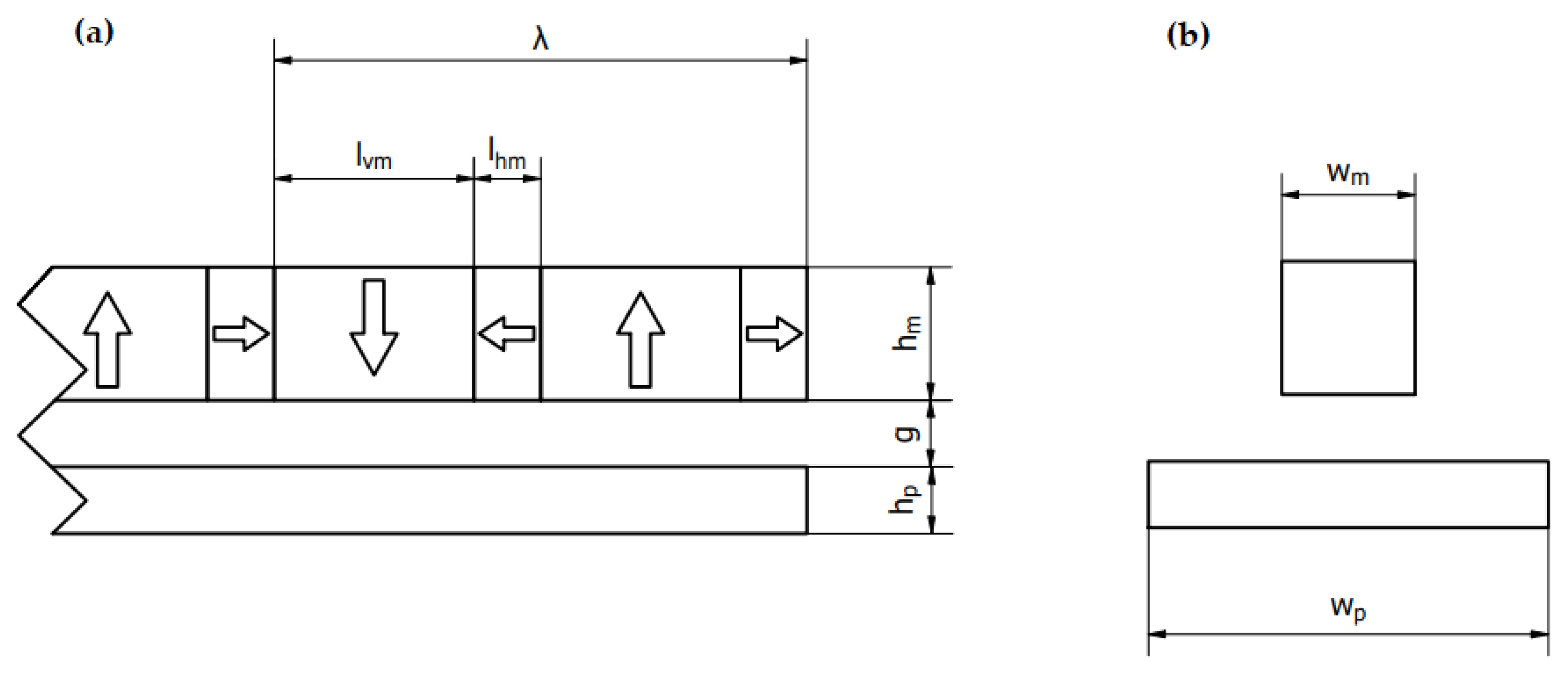
Figure 1. Halbach array with a wide vertically magnetized permanent magnet over a conductive track. Side view in picture (a) and front view in picture (b).
Energies 14 06549 g001
Figure 2. Examples of Halbach arrays with different fill factors. (a) γhm = 0.2, (b) γhm = 0.5 and (c) γhm = 0.85.
Energies 14 06549 g002
Figure 3. A section of the magnetic field in the air gap beneath the Halbach arrays. (a) Magnitude of magnetic induction, (b) x component of magnetic induction and (c) y component of magnetic induction.
Energies 14 06549 g003
Figure 4. Results obtained from transient simulations. (a) Levitation force as a function of velocity and fill factor, (b) braking force as a function of velocity and fill factor, (c) lift-to-drag ratio as a function of velocity and fill factor and (d) lift-to-weight as a function of velocity and fill factor.
Energies 14 06549 g004
Figure 5. Results obtained from transient simulations for vmax = 100 m/s. (a) Levitation force as a function of fill factor, (b) braking force as a function of fill factor, (c) lift-to-drag ratio as a function of fill factor and (d) lift-to-weight as a function fill factor.
Energies 14 06549 g005
Figure 6. Weights of vehicle body (yellow line), permanent magnets (red line) and sum of both (blue line). Weight of PM is calculated for vlew = 10 m/s.
Energies 14 06549 g006
Figure 7. (a) Rescaled levitation force as a function of velocity and fill factor and (b) rescaled braking force as a function of velocity and fill factor.
Energies 14 06549 g007
Figure 8. Instantaneous power required to overcome the braking forces. Power consumption as a function of fill factor and velocity.
Energies 14 06549 g008
Figure 9. Instantaneous power required to overcome the magnetic braking forces and its components (Equation (11)) at v = 100 m/s.
Energies 14 06549 g009
Figure 10. The difference of required power for fill factor = 0.5 and fill factor = 0.2 as a function of velocity.
Energies 14 06549 g010
Table 1. Simulations’ geometrical, material and dynamic parameters with descriptions.
Parameters TypeParameterSymbolValue
Geometrical parameters Wavelengthλ400 mm
PM’s heighthm50 mm
Conductive plate heighthp10 mm
Air gap sizeg30 mm
PM’s widthwm50 mm
Conductive plate widthwp120 mm
Material parametersPlate conductivitys32.47 MS/m
PM’s remanenceBr1.4 T
Dynamic parametersMax vehicle velocityvmax100 m/s
Levitation velocityvlev10 m/s
Mass of the vehicles bodymbody14,000 kg
Table 2. Comparison of average vales of magnitude of magnetic induction for different cases of fill factor.
γhm = 0.2γhm = 0.5γhm = 0.85
Bm_avg190 mT230 mT213 mT
Table 3. Comparison of ratio and absolute difference of required power for vehicle traveling with velocity = 100 m/s.
Pγhm = 0.5/Pγhm = 0.2Pγhm = 0.5 − Pγhm = 0.2
115%0.156 MW
Publisher’s Note: MDPI stays neutral with regard to jurisdictional claims in published maps and institutional affiliations.