Article

A New Concept of Air Cooling and Heat Pipe for Electric Vehicles in Fast Discharging

by
Hamidreza Behi
1,2,*,
Theodoros Kalogiannis
1,
Mahesh Suresh Patil
1,2,
Joeri Van Mierlo
1,2 and
Maitane Berecibar
1
1
Research group MOBI—Mobility, Logistics, and Automotive Technology Research Centre, Vrije Universiteit Brussel, Pleinlaan 2, 1050 Brussels, Belgium
2
Flanders Make, 3001 Heverlee, Belgium
*
Author to whom correspondence should be addressed.
Energies 2021, 14(20), 6477; https://doi.org/10.3390/en14206477
Submission received: 6 September 2021 / Revised: 29 September 2021 / Accepted: 5 October 2021 / Published: 10 October 2021
(This article belongs to the Special Issue Advanced Thermal Energy Conversion and Management Technologies)

Abstract

:
This paper presents the concept of a hybrid thermal management system (TMS) including natural convection, heat pipe, and air cooling assisted heat pipe (ACAH) for electric vehicles. Experimental and numerical tests are described to predict the thermal behavior of a lithium titanate oxide (LTO) battery cell in a fast discharging process (8C rate). Specifications of different cooling techniques are deliberated and compared. The mathematical models are solved by COMSOL Multiphysics® (Stockholm, Sweden), the commercial computational fluid dynamics (CFD) software. The simulation results are validated against experimental data with an acceptable error range. The results specify that the maximum cell temperatures for the cooling systems of natural convection, heat pipe, and ACAH reach 56, 46.3, and 38.3 °C, respectively. We found that the maximum cell temperature experiences a 17.3% and 31% reduction with the heat pipe and ACAH, respectively, compared with natural convection.

1. Introduction

In the past few decades, the usage of fossil fuels has produced lots of carbon dioxide and caused environmental issues [1]. The transportation industry, which is equipped with internal combustion engines, is known as one of the major sources of pollution. Therefore, electric vehicles (EVs) have received more attention as an ideal solution to decrease air pollution and global warming and combat the energy crisis. Lithium-ion (Li-ion) batteries are usually known for their unique features, including their long cycle life, favorable stability, high current, high power, and low self-discharge [2]. Regardless of the Li-ion suitable features, they generate considerable heat throughout the operation, particularly at high current profiles. It is more common to charge/discharge the Li-ion at a low current profile. Nevertheless, high acceleration and high climb need more energy, which leads to fast discharging. Once the temperature surpasses than a specified limit, it harmfully disturbs the Li-ion performance [3,4]. The ideal electrochemical performance of Li-ion batteries is between 25 °C and 40 °C with a maximum 5 °C temperature difference within the module/pack [5]. Since the heat generation of the Li-ion batteries is an inevitable phenomenon, designing an operative battery thermal management system (TMS) can guarantee the safe operation of Li-ion batteries. For that reason, different active and passive TMSs have been employed to progress the cooling performance of the Li-ion battery module/pack. Air cooling, liquid cooling, evaporative cooling, and refrigerant cooling are some examples of active cooling systems [6,7,8]. Moreover, phase change material (PCM), heat pipe, fin, mesh, and natural convection can be classified as passive cooling systems [9,10].
The air cooling system is the most common, low-cost, and simple structure to implement. Ambient temperature, air velocity, battery arrangement, and cooling channel size are the main factors for exploring the efficiency of the air cooling systems [11]. Behi et al. [12] considered the transient behavior of a cylindrical battery module in natural and forced air convection under a 1.5C discharging rate. They revealed an effective enhancement in the temperature uniformity for battery modules by forced-air cooling, heat pipe cooling, and heat pipe with copper sheets (HPCS) cooling system. Behi et al. [13] experimentally and numerically studied the air cooling effect on LTO cells in high-current applications in four different scenarios. They designed a sandwiched configuration of the heat pipes cooling system (SHCS) for TMS of the cell in high current discharging. However, because of the low heat transfer coefficient of air, a significant temperature difference can simply happen in a battery module/pack. Ye et al. [14] numerically considered and analyzed the effect of air cooling on the battery module under fast charging. They found that the air cooling method is impracticable at the pack level due to the low air heat transfer coefficient.
Liquid cooling and evaporative cooling systems are introduced as capable cooling systems by reason of the high heat transfer coefficient of the water [15]. Behi et al. [16] introduced a novel evaporative cooling system for a battery module made up of 30 cells. They studied the effect of evaporative cooling on module temperature in different inlet and outlet positions. Karimi et al. [17] experimentally and numerically studied the outcome of liquid cooling for a high-power lithium-ion capacitor (LiC). They found the maximum temperature of the LiC under the natural convection, forced convection, and liquid cooling reached 55.7 °C, 44.8 °C, and 32.6 °C, respectively. Nonetheless, the liquid cooling systems have weighty components and high investment costs. They have leakage and short circuit problems, as well [18].
PCM is known as a material that can absorb a considerable amount of energy during the phase change process at a constant temperature [19,20]. According to this special feature, PCMs are commonly applied in cooling and storage applications in the industry [21,22]. Behi et al. [23] studied the effect of a PCM-assisted heat pipe for cooling of the prismatic battery cell in a high current profile. They found the cell temperature decreased by 17.3% and 40.7% using the heat pipe and PCM-assisted heat pipe cooling methods, respectively. Karimi et al. [24] considered the effect of PCM and aluminum mesh on LiC module. They found that the combination of PCM aluminum mesh cooling system decreased the maximum module temperature by 20% and 13% in comparison with forced convection and pure PCM, respectively. Nevertheless, pure PCMs are not successful cooling systems due to the low thermal conductivity, which needs added materials such as nanoparticles, metal powders, fins, meshes, and heat pipes to compensate for this problem [25,26,27,28,29].
Heat pipes are famous as a two-phase heat transfer device with thermal conductivity of a copper rod in the same dimension. They can be used in many battery cooling applications due to their high thermal conductivity [30,31]. Behi et al. [32] investigated the cooling role of a heat pipe and air cooling on an LTO battery cell in the 8C discharging rate. They also experimentally calculated the thermal conductivity of the heat pipe. They found the single heat pipe could deliver up to 29.1% of the cell heat load in the 8C discharging rate. Mbulu et al. [33] explored the consequence of liquid cooling and L- and I-shaped heat pipes on battery thermal management. They considered the performance of the system at different boundary conditions. However, heat pipes are sensitive to gravity and design.
In the current study, an efficient and simple design of the heat pipe-based air cooling system is investigated for an LTO battery cell under fast discharging. With a strategic design, the low heat transfer coefficient of the air is compensated by the high thermal conductivity of heat pipes. Heat pipes are connected in the hot domain of the cell to maximize cooling efficiency. In addition, the secondary cooling system for heat pipe condensers is afforded by air cooling. The experimental results demonstrate that the heat pipe-based air cooling system is an operational TMS to control the temperature of the LTO cell under the 184 A current discharging. The study is organized as follows. Section 2 presents the experimental material, apparatus, and experimental results. The simulation, battery thermal model, forced air cooling model, validation, and simulation results are presented in Section 3. Finally, a relevant summary and outlook are drawn in Section 4.

2. Experimental Material, Apparatus, and Process

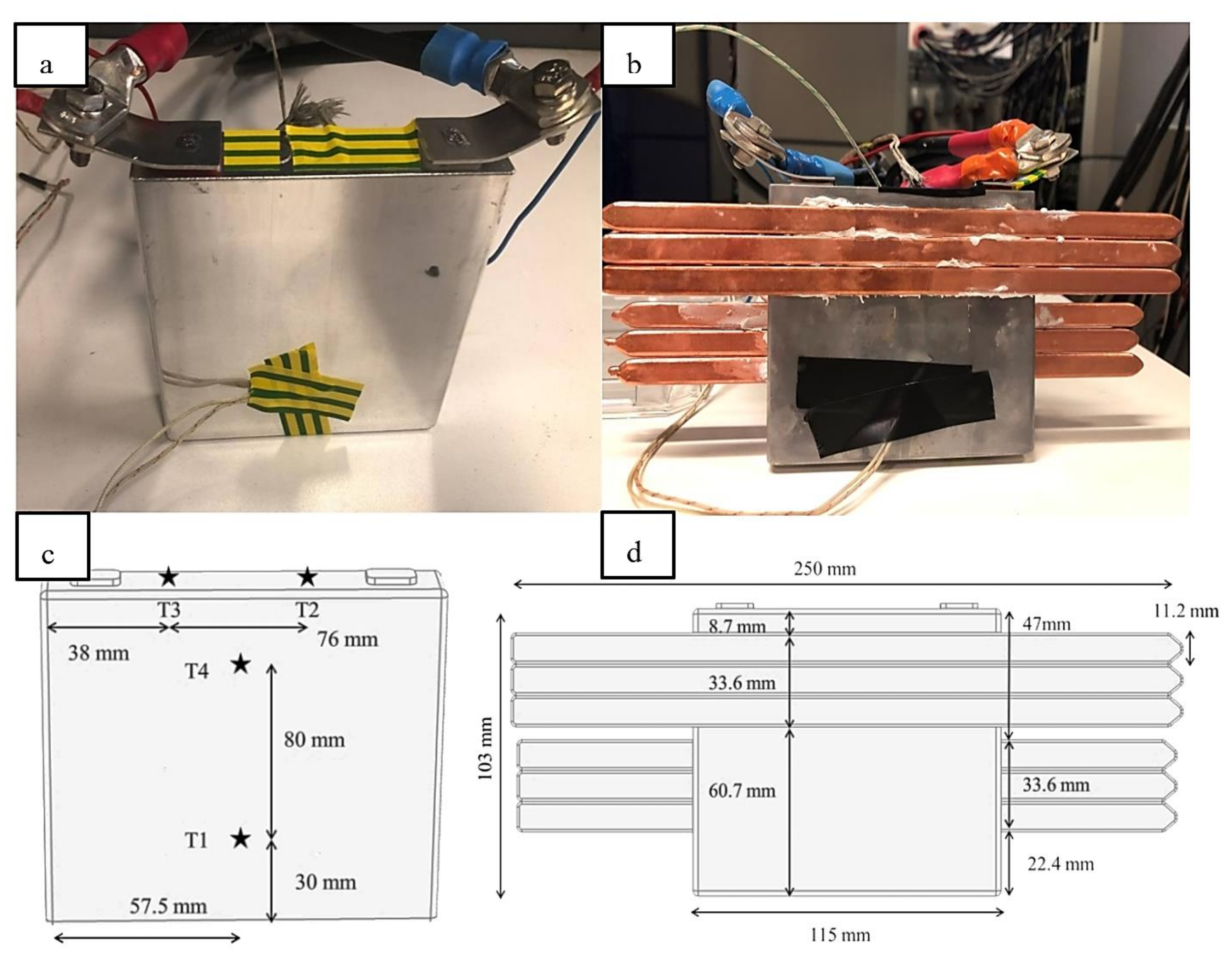
2.1. Explanation of the Materials

The test setup was constructed to examine the cooling effectiveness of the natural convection, heat pipe, and ACAH for the LTO battery cell in fast discharging. In the current paper, six flat heat pipes were used as a part of the TMS of the battery cell. The heat pipe envelope was made of copper. The heat pipe working fluid was distilled water and the wick structure was sintered. Usually, the heat pipes filled with water are more suitable for the temperature operation and thermal management of the batteries. The flat heat pipes benefit lower thermal contact resistance compared with traditional tubular heat pipes and are more effective for cooling claims. Heat transfer inside the heat pipe is repeated continuously. The heat produced by the cell and tabs is absorbed by the evaporator sections of the heat pipes. The working fluid inside the heat pipe evaporates and moves to the condenser section owing to increasing pressure. In condenser sections, heat is dissipated, and the working fluid is condensed. The capillary force returns the condensed working fluid to the evaporator. The important properties of the flat heat pipe are presented in Table 1.
Prismatic cells have recently been used in many EVs. Most of the prismatic cells are made of aluminum alloy, which is safer and lighter than stainless steel and other materials. Moreover, they need less space due to their specific shape. For the current study, a prismatic LTO cell was chosen for the experimental tests. The LTO cell was discharged by 184 A from 100% to 0% of the state of charge (SOC). The important properties of the LTO cell are listed in Table 2.

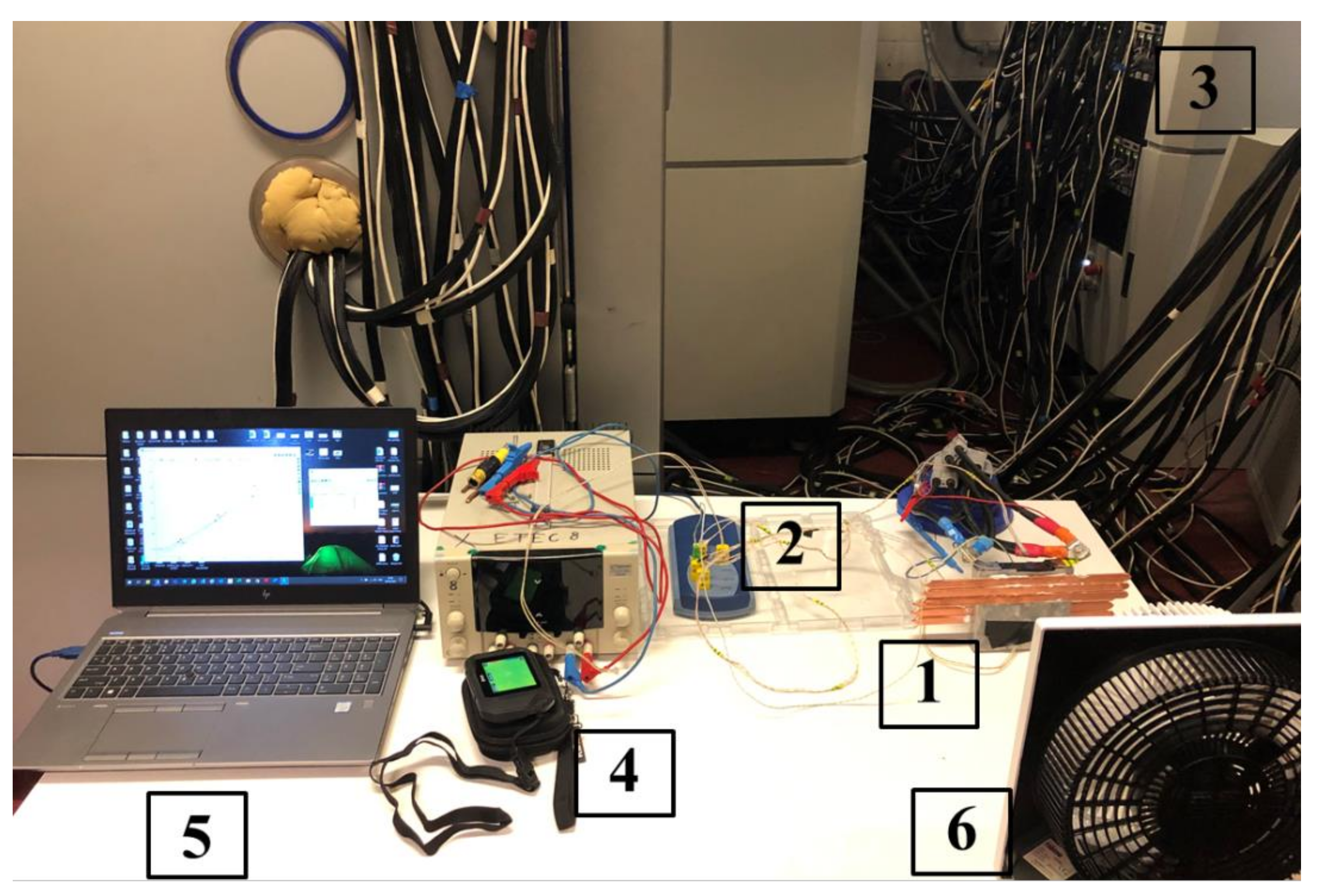
2.2. Explanation of the Test Sequence

In the present research, the cooling performance of the natural convection, heat pipe, and ACAH were studied on the LTO Li-ion cell in high current discharging. LTO was replaced instead of graphite in the anode section in common Li-ion batteries. This technology provides a new dimension of potential for energy storage with several economic and ecological features.
Figure 1 displays the schematic of the cell, heat pipe, thermocouples, and their dimension and locations. It is essential to mention that the thermocouples of T1 were located on the front side, T2 and T3 were located on the upside, and T4 was located on the backside of the cell. The location of the thermocouples was used intelligently to cover important sections of the cell (center and top). Figure 2 displays the apparatus used in current research. The experimental test rig involved an LTO battery cell, six flat heat pipes, a battery tester, a data acquisition system, K-type thermocouples, a Flir C2 thermal camera, and a laptop. All the thermocouples were calibrated with a precision of ±0.2 °C.
The tester was utilized for the charging and discharging of the LTO cell. The tests were performed at the constant room temperature of 22 °C and started with a status check of the battery cell. The LTO cell was charged by constant current followed by constant voltage phases (CCCV) and discharged with constant current (CC) for all tests. A laptop was connected for the data acquisition to record the cell temperature in four different sections of the cell. During the discharging, the voltage and current of the cell were recorded by the tester. In the experimental tests, the battery was discharged from 100% to 0% of SOC under the 8C in 446 seconds. The voltage, current, and resistance of the cell are characterized by the cycling of the battery. Palas and Newman [34] presented the following equation to calculate the heat generation of the cell:
m C p T t + q c o n v = k x   2 T x 2 + k y 2 T y 2 + k z 2 T z 2 + q g
where m , cp, T, k, and q g signify the mass, specific heat capacity, temperature, thermal conductivity, and heat generation of the battery, respectively.

2.3. Test Results and Discussion

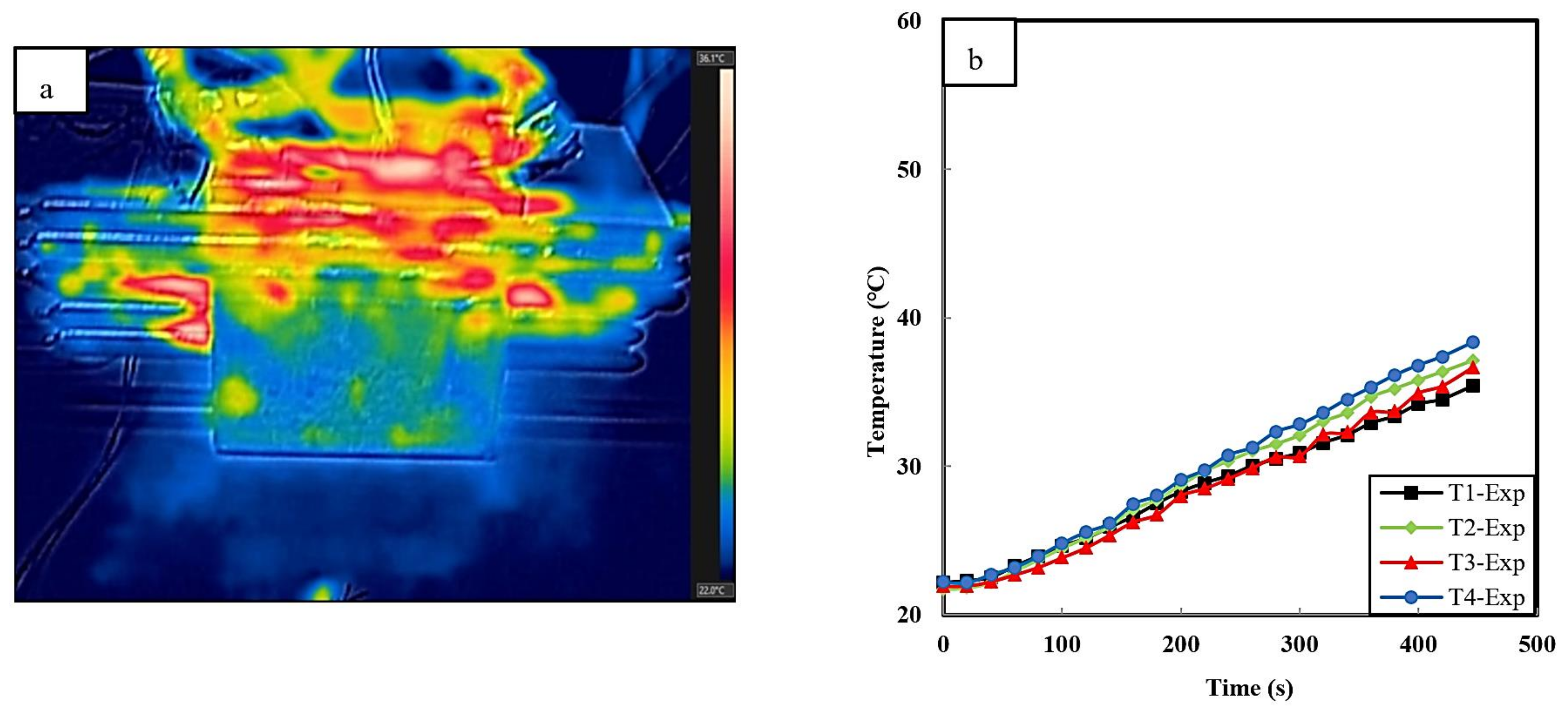
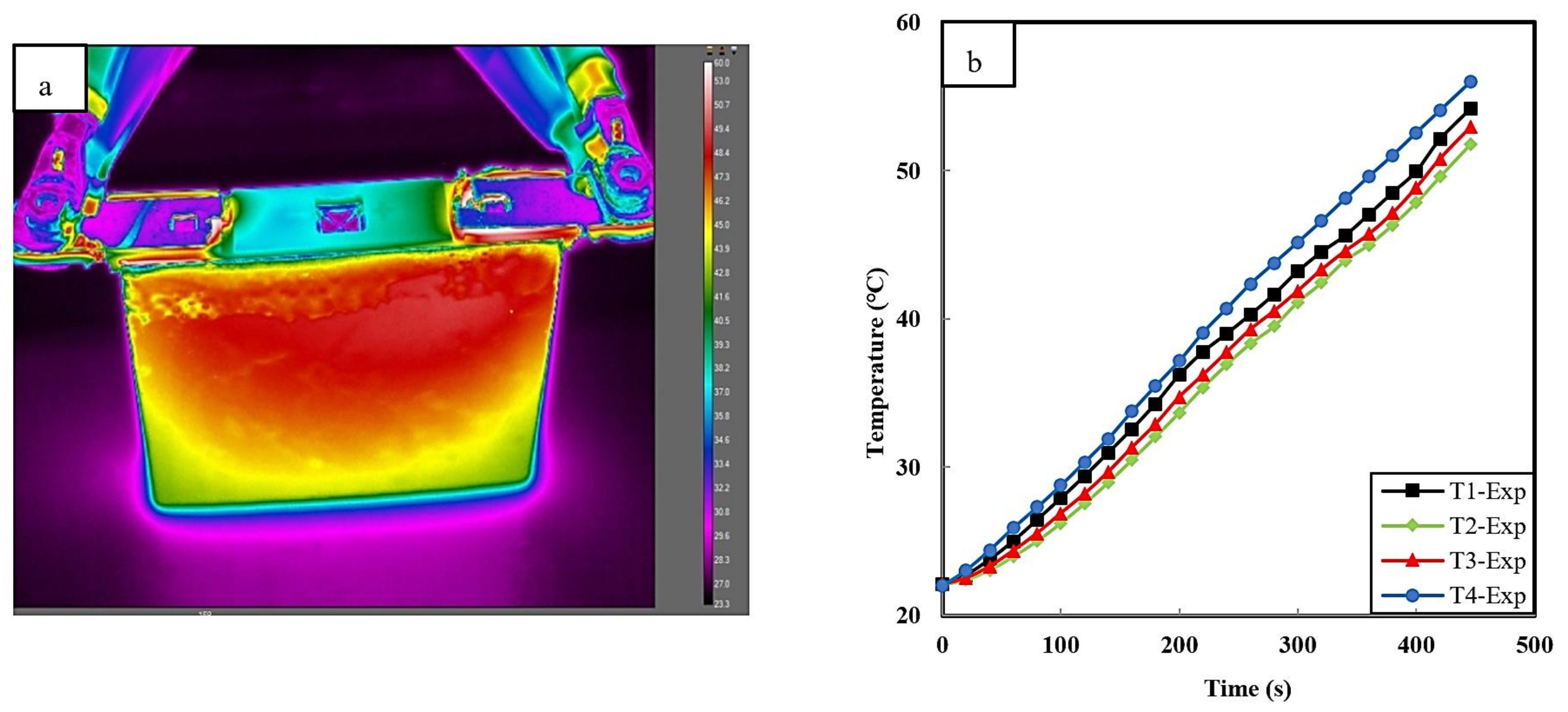
2.3.1. Effect of the Natural Convection on LTO Cell

Figure 3a,b display the thermal image and temperature discrepancy of the cell in the natural convection at a room temperature of 22 °C and under the 8C discharging rate. Natural convection is used as an initial cooling method that benefits no cooling energy consumption. Moreover, this cooling system successfully contributes to saving the budget and volume by removing the fan. The results shows that the trend of the temperatures is almost the same, with a maximum temperature difference of 5 °C. The maximum temperature of the cell reaches 56 °C, demonstrating that the natural convection cooling method is not successful to control the cell temperature within the appropriate range. In natural convection, the battery heat generation is largely removed through conduction. Therefore, given the lack of air heat transfer coefficient, the heat removal is not sufficient.

2.3.2. Effect of the Natural Convection and Heat Pipes on the LTO Cell

According to the previous experiment, natural convection is not satisfactory to control the cell temperature in fast discharging. Therefore, a cooling concept using the six heat pipes as superconductors was designed to increase the heat transfer efficiency. Explicitly, there is a hot zone inside the cell with more concentration at the top and center of the cell. The heat pipes are connected in the hot zone of the cell, which is shown in Figure 1d. The top and center of the cell have the hottest zones, covered by heat pipes [35]. The heat pipes are connected to the hot domain of the cell with the purpose of maximizing the heat transfer capability. Moreover, every heat pipe benefits from two condensers to maximize cooling efficiency [23]. The focus of this section is to use the features of high conductive heat pipes to decrease the maximum cell temperature and increase the temperature uniformity. According to Figure 4a, the temperature uniformity increased due to the heat pipes cooling and the high thermal conductivity effect. The maximum temperature of the cell reached 46.3 °C, a 17.3% decrease compared with the previous experiment. The ordering temperature of the different thermocouples changed due to the cooling effect of heat pipes. The hot temperature zone migrated from the top to the center and the downside of the cell. Nevertheless, the cell temperature must be modified to reach the optimum operating range (25–40 °C).

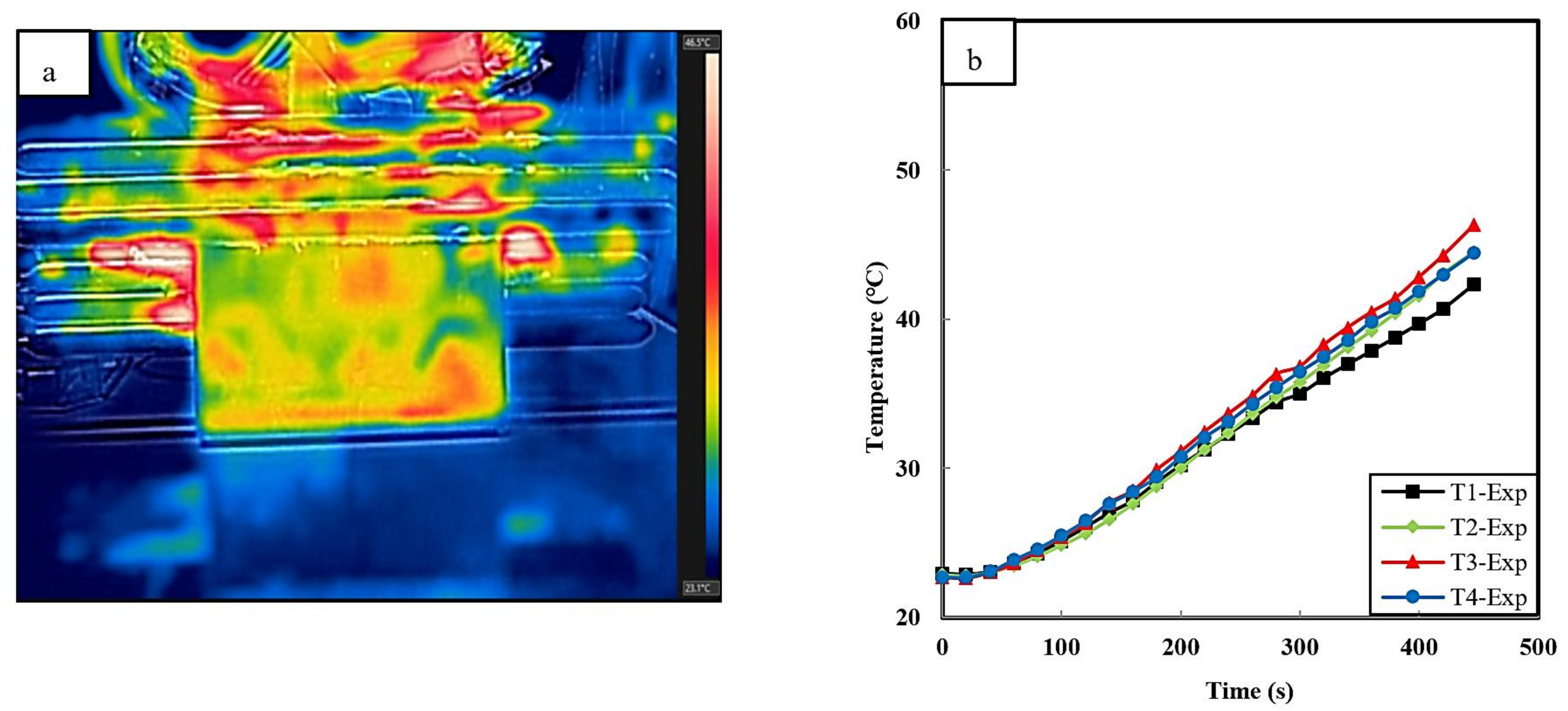
2.3.3. Effect of the ACAH on the LTO Cell

In order to enhance the cooling target, an experimental ACAH was designed. In this design, the cell equipped with heat pipes is affected by forced convection (Figure 5). The fan with an inlet velocity of 3 m/s directly affects the cell, evaporator, and condensers of the heat pipes. The designed hybrid cooling system is promoted by the high thermal conductivity of heat pipes and the low cost of forced air cooling. The maximum temperature of the cell reached 38.3 °C at the 31% and 17.2% reduction compared with natural convection and heat pipe cooling system, respectively.

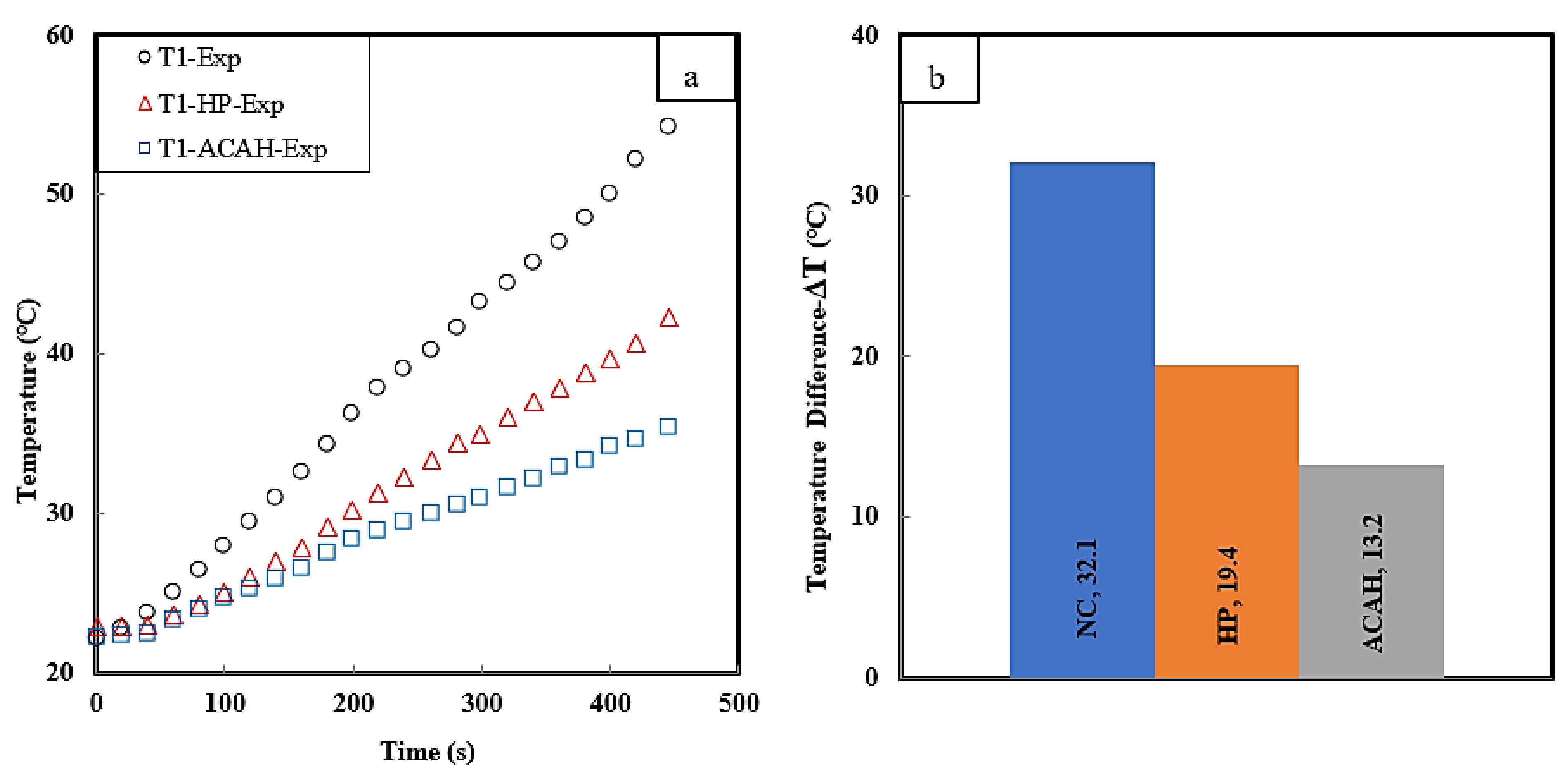
2.3.4. Comparison of the T1 Thermocouple in Various Cooling Strategies

In order to consider the cooling efficiency of proposed cooling systems, the temperature transient response of the T1 thermocouple is plotted in Figure 6a. For the natural convection scenario, the T1 temperature reached 54.2 °C at the end of the cycle. For the second and third scenarios, due to the effect of the heat pipe and forced convection, the temperature of T1 reached 42.3 °C and 35.4 °C, respectively. Figure 6b displays the temperature difference (ΔT) of T1. ΔT is a way of expressing temperature when conducting temperature tests and is calculated by subtracting the final battery temperature from the initial battery temperature. We found that the heat pipe and ACAH decreased the ΔT by 39% and 58% compared with natural convection, respectively.

3. Simulation and Modeling

3.1. LTO Cell Numerical Thermal Modeling

MATLAB/Simulink and COMSOL Multiphysics® were applied for the thermal model of the battery cell. The internal heat source (ohmic resistance) of the battery was provided by a dual-polarization model [16]. Internal and external heat sources contributed to the rise in the temperature of the cell. The internal heat source returns to the chemical reaction inside the cell domain. The external heat source returns to the positive and negative tabs, which are related to the resistive loss and the current square. A number of parameters such as specific heat capacity were attained from the MATLAB/Simulink and the rest, including density, mass, and thermal conductivity, were taken from the cell datasheet. Figure 7 shows the impedance model, consisting of open-circuit voltage (Voc), ohmic resistance (R0), polarization resistance (R1), and electrochemical resistance (R2).
A number of characterization experiments were performed to achieve the parameters of the impedance model. The battery cell heat generation is considered by Joule losses.
q g = R 0 · I b a t t 2 + R 1 · I 1 2 + R 2 · I 2 2
where q g represents the battery heat generation. An energy balance is used (Equation (1)) for the effect of battery heat generation and convection. Additionally, Equation (3) presents the tab domain heat production [36].
q ˙ = R t a b · I b a t t 2
R t a b = ρ   l A
For the tab domains, R t a b , ρ , l , and A represent the resistance of the tab, resistivity, length, and cross-section of the tab, respectively. The convective heat transfer is presented as follows [37]:
q c o n v = h × A T b a t t T a m b
where h and A show the heat transfer coefficient and cross-section area of the cell, respectively. In addition, T b a t t and T a m b reveal the battery and room temperature, respectively.

3.2. Forced Air Cooling Model

The equations of continuity, energy conservation, and momentum conservation were considered in the simulation model to calculate the flow field and temperature distribution of the module as follows [38]:
· υ = 0
ρ a C a T a t + · ρ a C a υ T a = · λ a T a
ρ a d υ d t = p + μ a 2 υ
In Equations (7)–(9), the υ , ρ a , C a , λ a , μ a , p, and T a signify the inlet air’s velocity, mass density, specific heat capacity, thermal conductivity, dynamic viscosity, pressure, and temperature, respectively. The Reynolds number is calculated to specify the flow regime.
R e = ρ · V · D h μ
According to the calculation results, the flow state was turbulent. Consequently, the k ε turbulent model was selected for the simulations. The turbulent governing equations are specified as follows [39]:
t ρ λ + x j ρ λ μ j = x j μ + μ t α k λ x j + G k + G b ρ ε Y M + S λ
t ρ ε + x j ρ ε μ j = x j μ + μ t α ε ε x j + C 1 ε ε k G k + C 3 ε + G b ρ C 2 ε ε 2 k + S ε
In Equations (10) and (11) λ , ε , μ , and μ t   signify the turbulent kinetic energy, turbulent dissipation rate, molecular dynamic viscosity coefficient, and turbulent dynamic viscosity coefficient.

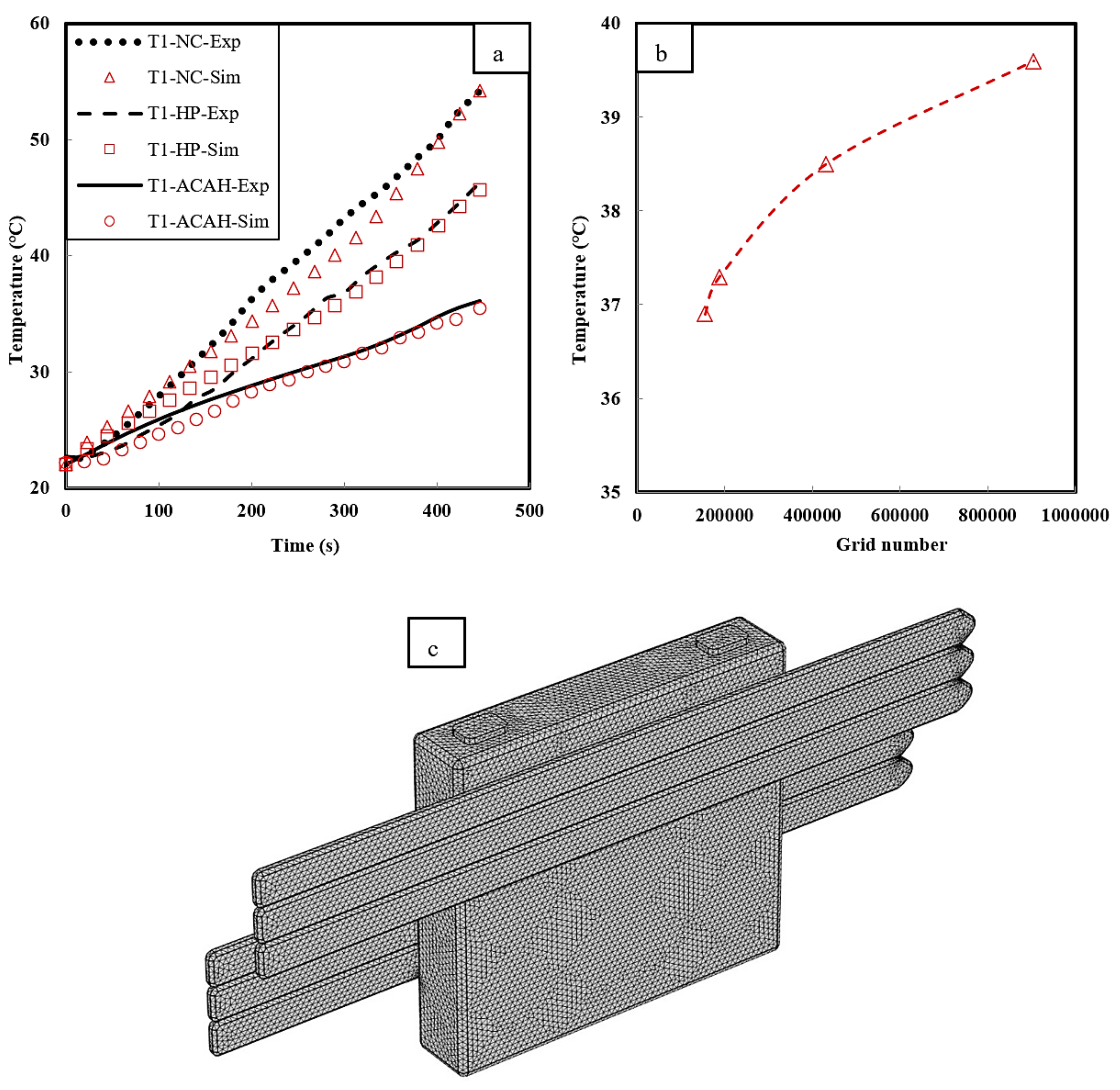
3.3. Validation of Battery Cell for Natural Convection, Heat Pipe, ACAH, and Grid Number Sensitivity Analysis

For validation of the battery thermal model, the simulation and experimental data were compared for the different cooling conditions. The cell surface temperature was measured by four K-type thermocouples in different domains of the battery. The discharging process finished once the voltage of the cell dropped from 2.7 V to 1.5 V. To confirm the precision of the simulation, the thermocouple of T1 was selected for validation. Figure 8a shows an adequate similarity among the simulation and experimental results for different scenarios. In addition, in order to ensure the precise simulation result, a grid number independence study was carried out. To this end, the geometry was meshed by an unstructured tetrahedral mesh (Figure 8c). The initial temperature of the test setup and coolant was set at 22 °C and the inlet velocity of the coolant was set at 3 m/s. The k ε turbulent model was selected for the ACAH simulations. The radiation heat transfer was expected to be negligible.
Figure 8b shows the maximum cell temperature by ACAH to consider the grid number sensitivity analysis. The result fluctuates only by 2% when the grid number differs from 430,903 to 904,737. Consequently, as a result of computational time-saving, the grid number 430,903 was selected for the cell-level simulation.

3.4. Simulation Results and Discussion

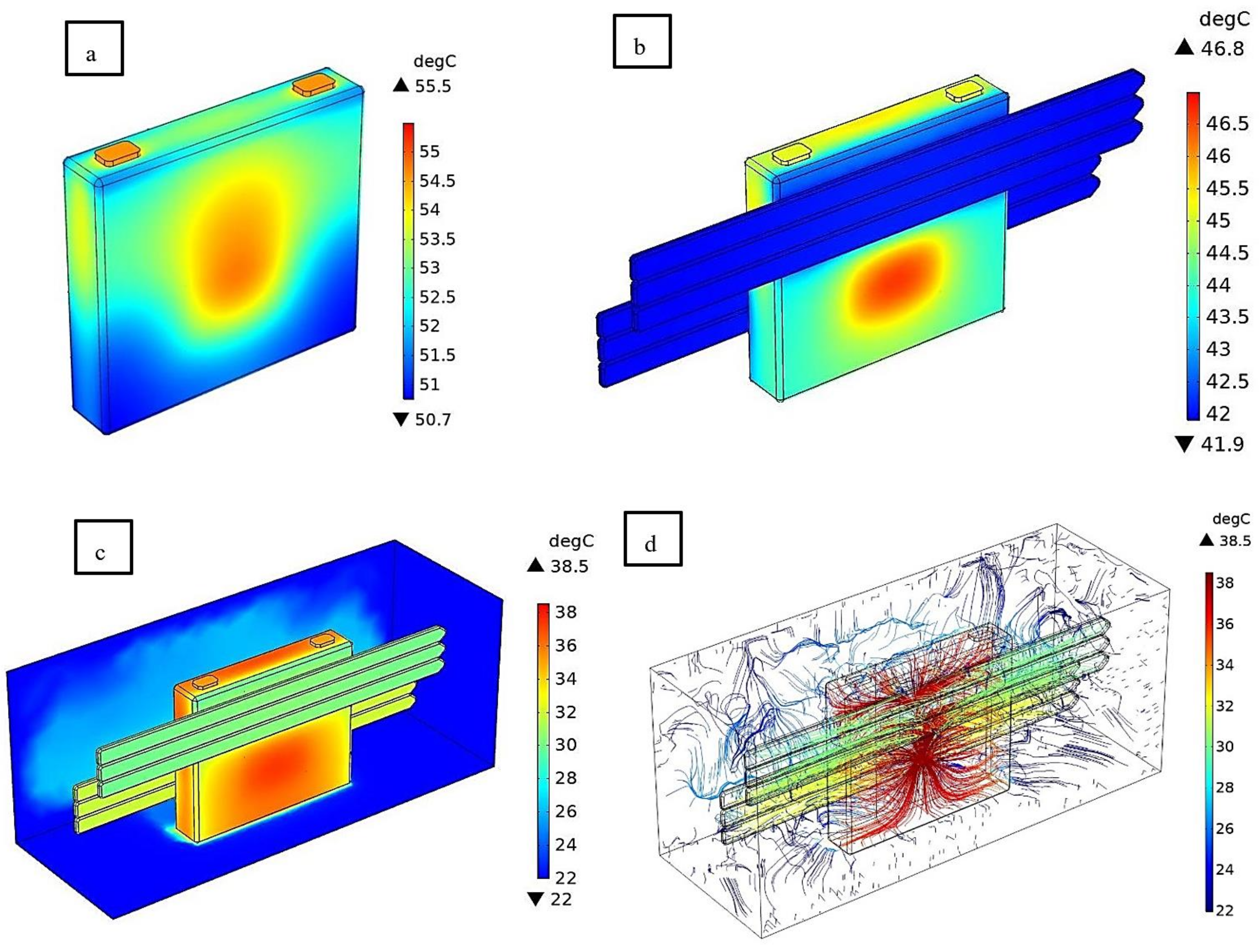
3.4.1. The Effect of Natural Convection, Heat Pipe, and ACAH Cooling Methods on the Cell Level

Figure 9 displays the temperature contour of the cell under the cooling performance of the natural convection, heat pipe, and ACAH at a fast discharging rate of 8C from 100% to 0% of SOC. The heat generation of the cell cannot be controlled in the presence of natural convection because of the low heat transfer capacity of the air. It is obvious that there are several hot domains in the center, top, and tab of the cell that need special attention for thermal management. In the second scenario, the cooling potential of heat pipes as superconductors are considered in natural convection conditions. The heat pipes are wisely sticking to the cell and in the hot zones in order to use the maximum potential of natural convection to decrease the cell temperature and increase uniformity. The heat pipes have positive effects on cell heat removal. According to the third scenario, the time-dependent simulation for the cell embedded ACAH has a significant effect on the thermal management of the cell. It is important to mention that in the simulation, the heat pipe was substituted with a solid domain with the effective thermal conductivity of 8212 W/m.K [12,13,19,32,40].

3.4.2. Effect of Different Coolant Velocity on ACAH Cooling Method

Using ACAH is a successful method for thermal management of the LTO cell under fast discharging. The cooling effect of ACAH is extremely dependent on its coolant inlet velocity, temperature, and flow path. Therefore, the influence of inlet on cell temperature velocity is considered in Table 3. As is expected, the cell temperature decreased by increasing the inlet velocity. In fact, by increasing the coolant velocity, the air volume of the battery box increases, which can accelerate heat exchange between the cell surface and coolant. The inlet air velocity is fixed at 1 m/s, 2 m/s, 3 m/s, 4 m/s, and 5 m/s, which results in 45.24, 40.96, 38.55, 36.96, and 35.83 °C, respectively. The initial cell temperature is shown by the blue color and the final temperature by the red color. It is obvious that the inlet velocity of 3 m/s and greater can preserve the temperature of the cell in an ideal range (25–40 °C).

3.4.3. Effect of Different Ambient Temperatures on ACAH Cooling Method

Ambient temperature is a critical item for air cooling that can directly affect the capacity and lifetime of the battery cell. Low ambient and operating temperature cause sluggish chemical reaction action, which leads to the reduction of ionic conductivity in the electrolytes and Li-ion diffusivity within the electrodes. This reduction leads to a decrease in energy and power capability. On the other hand, high temperatures result in the performance degradation of the batteries and reduction of the lifetime. Therefore, optimal ambient and operation temperatures (25–40 °C) are important for battery life and capacity. As shown in Table 4, the transient temperature of LTO cell under the 8C discharging rate in ambient temperatures of 10, 22, 35, and 45 °C was investigated. The ambient temperature directly influences the temperature of the cell. The maximum temperature of the cell in ambient temperatures of 10, 22, 35, and 45 °C reached 26.56, 38.55, 51.35, and 61.51 °C, respectively. Since in air cooling, the inlet air comes from ambient, this system is not an effective cooling method in high ambient temperatures.

4. Summary and Outlook

4.1. Conclusions

The presented study was experimentally and numerically designed to consider the cooling efficiency of the natural convection, heat pipe, and ACAH for an LTO battery cell under an 8C discharging rate. The results are determined as follows:
  • The cell surface temperature at four different points is measured in the presence of natural convection. The maximum temperature is reached 56 °C at an ambient temperature of 22 °C.
  • Heat pipe and natural convection could reduce the maximum cell temperature by 17.3%.
  • Using the ACAH, the maximum cell temperature reached 38.3 °C, experiencing a 31% decrease.
  • The mathematical models were solved by COMSOL Multiphysics®. The simulation results for different scenarios were validated against experimental data with an acceptable error range.
  • The influence of different inlet velocities and ambient temperatures on the cell maximum temperature was investigated for the ACAH cooling method.

4.2. Future Work

The features of using the ACAH cooling system can be studied for different C-rates. The cooling effect of heat pipes can be considered from different angles as the heat pipe is gravity-dependent. Additionally, the consequence of the presented cooling systems can be examined at the module/pack level.

Author Contributions

Writing—original draft, test setup, experimental tests, simulation, H.B.; review and editing, T.K., M.S.P. and J.V.M.; supervision, M.B. All authors have read and agreed to the published version of the manuscript.

Funding

European Union’s Horizon 2020, grant agreement No. 824290.

Institutional Review Board Statement

Not applicable.

Informed Consent Statement

Not applicable.

Data Availability Statement

The supporting data will be made available on request.

Acknowledgments

The existing research belongs to the SELFIE project. Furthermore, the authors acknowledge ‘Flanders Make’ for the support of the MOBI research group.

Conflicts of Interest

The authors declare no conflict of interest.

References

  1. Ghezelbash, R.; Farzaneh-Gord, M.; Behi, H.; Sadi, M.; Khorramabady, H.S. Performance assessment of a natural gas expansion plant integrated with a vertical ground-coupled heat pump. Energy 2015, 93, 2503–2517. [Google Scholar] [CrossRef]
  2. Khaleghi, S.; Karimi, D.; Beheshti, S.H.; Hosen, S.; Behi, H.; Berecibar, M.; Van Mierlo, J. Online health diagnosis of lithium-ion batteries based on nonlinear autoregressive neural network. Appl. Energy 2021, 282, 116159. [Google Scholar] [CrossRef]
  3. Karimi, D.; Khaleghi, S.; Behi, H.; Beheshti, H.; Hosen, S.; Akbarzadeh, M.; Van Mierlo, J.; Berecibar, M. Lithium-Ion Capacitor Lifetime Extension through an Optimal Thermal Management System for Smart Grid Applications. Energies 2021, 14, 2907. [Google Scholar] [CrossRef]
  4. Karimi, D.; Behi, H.; Akbarzadeh, M.; Van Mierlo, J.; Berecibar, M. Holistic 1D Electro-Thermal Model Coupled to 3D Thermal Model for Hybrid Passive Cooling System Analysis in Electric Vehicles. Energies 2021, 14, 5924. [Google Scholar] [CrossRef]
  5. Behi, H.; Karimi, D.; Jaguemont, J.; Gandoman, F.H.; Khaleghi, S.; Van Mierlo, J.; Berecibar, M. Aluminum Heat Sink Assisted Air-Cooling Thermal Management System for High Current Applications in Electric Vehicles. In 2020 AEIT International Conference of Electrical and Electronic Technologies for Automotive (AEIT AUTOMOTIVE); IEEE: Turin, Italy, 2020. [Google Scholar] [CrossRef]
  6. Karimi, D.; Behi, H.; Jaguemont, J.; Berecibar, M.; van Mierlo, J. A refrigerant-based thermal management system for a fast charging process for lithium-ion batteries. In Proceedings of the International Conference on Renewable Energy Systems and Environmental Engineering (IRESE2020), Brussels, Belgium, 18–20 July 2020; pp. 1–6. [Google Scholar]
  7. Karimi, D.; Behi, H.; Jaguemont, J.; Berecibar, M.; van Mierlo, J. Investigation of extruded heat sink assisted air cooling system for lithium-ion capacitor batteries. In Proceedings of the International Conference on Renewable Energy Systems and Environmental Engineering, Brussels, Belgium, 18–20 July 2020; pp. 1–6. [Google Scholar]
  8. Yahyaie, A.; Mirmohammadi, S.A.A.; Behi, M.R.; Sadi, M.; Behi, H.R. Theoretical Investigation on Producing Work by Applying Different Refrigerants in Typical Power Cycle, Scientific Society of Measurement, Automation and Informatics, Branch of Thermal Engineering and Thermogrammetry, Hungary. 2009. Available online: http://inis.iaea.org/search/search.aspx?orig_q=RN:40102982 (accessed on 10 September 2021).
  9. Gandoman, F.H.; Behi, H.; Berecibar, M.; Jaguemont, J.; Aleem, S.H.A.; Behi, M.; Van Mierlo, J. Reliability evaluation of Li-ion batteries for electric vehicles applications from the thermal perspectives. In Uncertainties in Modern Power Systems; Elsevier; Academic Press: Cambridge, MA, USA, 2021; pp. 563–587. [Google Scholar]
  10. Karimi, D.; Jaguemont, J.; Behi, H.; Berecibar, M.; van den Bossche, P.; van Mierlo, J. Passive cooling based battery thermal management using phase change materials for electric vehicles. In Proceedings of the EVS33 International Electric Vehicle Symposium, Portland, OR, USA, 14–17 June 2020; The Electric Drive Transportation Association EDTA: Portland, OR, USA, 2020. [Google Scholar]
  11. Karimi, D.; Behi, H.; Jaguemont, J.; Berecibar, M.; van Mierlo, J. Optimized air-cooling thermal management system for high power lithium-ion capacitors. In Proceedings of the International Conference on Renewable Energy Systems and Environmental Engineering (IRESE2020), Brussels, Belgium, 18–20 July 2020. [Google Scholar]
  12. Behi, H.; Karimi, D.; Behi, M.; Ghanbarpour, M.; Jaguemont, J.; Sokkeh, M.A.; Gandoman, F.H.; Berecibar, M.; Van Mierlo, J. A new concept of thermal management system in Li-ion battery using air cooling and heat pipe for electric vehicles. Appl. Therm. Eng. 2020, 174, 115280. [Google Scholar] [CrossRef]
  13. Behi, H.; Behi, M.; Karimi, D.; Jaguemont, J.; Ghanbarpour, M.; Behnia, M.; Berecibar, M.; Van Mierlo, J. Heat pipe air-cooled thermal management system for lithium-ion batteries: High power applications. Appl. Therm. Eng. 2021, 183, 116240. [Google Scholar] [CrossRef]
  14. Ye, Y.; Saw, B.; Shi, Y.; Tay, A.A. Numerical analyses on optimizing a heat pipe thermal management system for lithium-ion batteries during fast charging. Appl. Therm. Eng. 2015, 86, 281–291. [Google Scholar] [CrossRef]
  15. Karimi, D.; Behi, H.; Jaguemont, J.; El Baghdadi, M.; Van Mierlo, J.; Hegazy, O. Thermal Concept Design of MOSFET Power Modules in Inverter Subsystems for Electric Vehicles. In Proceedings of the 2019 9th International Conference on Power and Energy Systems (ICPES), Perth, WA, Australia, 10–12 December 2019; pp. 1–6. [Google Scholar]
  16. Behi, H.; Karimi, D.; Jaguemont, J.; Gandoman, F.H.; Kalogiannis, T.; Berecibar, M.; Van Mierlo, J. Novel thermal management methods to improve the performance of the Li-ion batteries in high discharge current applications. Energy 2021, 224, 120165. [Google Scholar] [CrossRef]
  17. Karimi, D.; Behi, H.; Hosen, S.; Jaguemont, J.; Berecibar, M.; Van Mierlo, J. A compact and optimized liquid-cooled thermal management system for high power lithium-ion capacitors. Appl. Therm. Eng. 2021, 185, 116449. [Google Scholar] [CrossRef]
  18. Karimi, D.; Hosen, S.; Behi, H.; Khaleghi, S.; Akbarzadeh, M.; Van Mierlo, J.; Berecibar, M. A hybrid thermal management system for high power lithium-ion capacitors combining heat pipe with phase change materials. Heliyon 2021, 7, 07773. [Google Scholar] [CrossRef]
  19. Behi, H. Experimental and Numerical Study on Heat Pipe Assisted PCM Storage System. Master’s Thesis, Royal Institute of Technology, Stockholm, Sweden, 2015. Available online: http://www.diva-portal.org/smash/get/diva2:850104/FULLTEXT01.pdf (accessed on 10 September 2021).
  20. Behi, H.; Behi, M.; Ghanbarpour, A.; Karimi, D.; Azad, A.; Ghanbarpour, M.; Behnia, M. Enhancement of the Thermal Energy Storage Using Heat-Pipe-Assisted Phase Change Material. Energies 2021, 14, 6176. [Google Scholar] [CrossRef]
  21. Behi, M.; Mirmohammadi, S.A.; Suma, A.B.; Palm, B.E. Optimized Energy Recovery in Line With Balancing of an ATES. In Proceedings of the ASME 2014 Power Conference, Baltimore, MD, USA, 28–31 July 2014. [Google Scholar] [CrossRef]
  22. Behi, M.; Mirmohammadi, S.A.; Ghanbarpour, M.; Behi, H.; Palm, B. Evaluation of a novel solar driven sorption cooling/heating system integrated with PCM storage compartment. Energy 2018, 164, 449–464. [Google Scholar] [CrossRef]
  23. Behi, H.; Karimi, D.; Gandoman, F.H.; Akbarzadeh, M.; Khaleghi, S.; Kalogiannis, T.; Hosen, S.; Jaguemont, J.; Van Mierlo, J.; Berecibar, M. PCM assisted heat pipe cooling system for the thermal management of an LTO cell for high-current profiles. Case Stud. Therm. Eng. 2021, 25, 100920. [Google Scholar] [CrossRef]
  24. Karimi, D.; Behi, H.; Jaguemont, J.; Sokkeh, M.A.; Kalogiannis, T.; Hosen, S.; Berecibar, M.; Van Mierlo, J. Thermal performance enhancement of phase change material using aluminum-mesh grid foil for lithium-capacitor modules. J. Energy Storage 2020, 30, 101508. [Google Scholar] [CrossRef]
  25. Mirmohammadi, S.; Behi, M. Investigation on Thermal Conductivity, Viscosity and Stability of Nanofluids. 2012, p. 140. Available online: http://kth.diva-portal.org/smash/record.jsf?pid=diva2:537164 (accessed on 10 September 2021).
  26. Mirmohammadi, S.A.; Behi, M.; Gan, Y.; Shen, L. Particle-shape-, temperature-, and concentration-dependent thermal conductivity and viscosity of nanofluids. Phys. Rev. E 2019, 99, 043109. [Google Scholar] [CrossRef] [PubMed] [Green Version]
  27. Nikkam, N.; Saleemi, M.; Behi, M.; Khodabandeh, R.; Toprak, M.S. Experimental investigation on the effect of SiO2 secondary phase on thermo-physical properties of SiC nanofluids. Int. Commun. Heat Mass Transf. 2017, 87, 164–168. [Google Scholar] [CrossRef]
  28. Behi, H.; Karimi, D.; Youssef, R.; Patil, M.S.; Van Mierlo, J.; Berecibar, M. Comprehensive Passive Thermal Management Systems for Electric Vehicles. Energies 2021, 14, 3881. [Google Scholar] [CrossRef]
  29. Behi, M.; Shakorian-Poor, M.; Mirmohammadi, S.; Behi, H.; Rubio, J.; Nikkam, N.; Farzaneh-Gord, M.; Gan, Y.; Behnia, M. Experimental and numerical investigation on hydrothermal performance of nanofluids in micro-tubes. Energy 2020, 193, 116658. [Google Scholar] [CrossRef]
  30. Behi, H.; Ghanbarpour, M.; Behi, M. Investigation of PCM-assisted heat pipe for electronic cooling. Appl. Therm. Eng. 2017, 127, 1132–1142. [Google Scholar] [CrossRef]
  31. Behi, H.; Karimi, D.; Jaguemont, J.; Berecibar, M.; van Mierlo, J. Experimental study on cooling performance of flat heat pipe for lithium-ion battery at various inclination angels. Energy Perspect. 2020, 1, 77–92. [Google Scholar]
  32. Behi, H.; Karimi, D.; Behi, M.; Jaguemont, J.; Ghanbarpour, M.; Behnia, M.; Berecibar, M.; Van Mierlo, J. Thermal management analysis using heat pipe in the high current discharging of lithium-ion battery in electric vehicles. J. Energy Storage 2020, 32, 101893. [Google Scholar] [CrossRef]
  33. Mbulu, H.; Laoonual, Y.; Wongwises, S. Experimental study on the thermal performance of a battery thermal management system using heat pipes. Case Stud. Therm. Eng. 2021, 26, 101029. [Google Scholar] [CrossRef]
  34. Ashwin, T.; Chung, Y.M.; Wang, J. Capacity fade modelling of lithium-ion battery under cyclic loading conditions. J. Power Sources 2016, 328, 586–598. [Google Scholar] [CrossRef] [Green Version]
  35. Kariya, H.A. Development of an Air-cooled, Loop-type Heat Pipe with Multiple Condensers. 2012, pp. 1–172. Available online: https://dspace.mit.edu/handle/1721.1/78237 (accessed on 10 September 2021).
  36. Soltani, M.; Ronsmans, J.; Jaguemont, J.; Van Mierlo, J.; Bossche, P.V.D.; Omar, N. A Three-dimensional thermal model for a commercial lithium-ion capacitor battery pack with non-uniform temperature distribution. In Proceedings of the 2019 IEEE International Conference on Industrial Technology (ICIT), Melbourne, VIC, Australia, 13–15 February 2019; pp. 1126–1131. [Google Scholar] [CrossRef]
  37. Jaguemont, J.; Boulon, L.; Dubé, Y. Characterization and Modeling of a Hybrid-Electric-Vehicle Lithium-Ion Battery Pack at Low Temperatures. IEEE Trans. Veh. Technol. 2016, 65, 1–14. [Google Scholar] [CrossRef] [Green Version]
  38. Li, W.; Xiao, M.; Peng, X.; Garg, A.; Gao, L. A surrogate thermal modeling and parametric optimization of battery pack with air cooling for EVs. Appl. Therm. Eng. 2019, 147, 90–100. [Google Scholar] [CrossRef]
  39. Zhang, F.; Lin, A.; Wang, P.; Liu, P. Optimization design of a parallel air-cooled battery thermal management system with spoilers. Appl. Therm. Eng. 2021, 182, 116062. [Google Scholar] [CrossRef]
  40. Ghanbarpour, M.; Khodabandeh, R. Entropy generation analysis of cylindrical heat pipe using nanofluid. Thermochim. Acta 2015, 610, 37–46. [Google Scholar] [CrossRef]
Figure 1. Picture of the (a) LTO prismatic cell; (b) cell equipped with heat pipes; (c) schematic location of thermocouples (T1 front side, T2 and T3 upside, and T4 back side of the cell); (d) dimension of the cell and heat pipes.
Energies 14 06477 g001
Figure 2. The image of the apparatus consisting of (1) cell and heat pipe, (2) data acquisition system and thermocouples, (3) battery tester, (4) thermal camera, (5) laptop, and (6) cooling fan.
Energies 14 06477 g002
Figure 3. (a) The thermal image of the cell at the end of discharging process (446 s); (b) temperature difference of the LTO cell in presence of the natural convection (room temperature: 22 °C, discharging rate: 8C, Exp: experimental).
Energies 14 06477 g003
Figure 4. (a)The thermal image of the cell equipped with heat pipes at the end of discharging process (446 s); (b) temperature difference of the LTO cell equipped with heat pipes in presence of the natural convection (room temperature: 22 °C; discharging rate: 8C).
Energies 14 06477 g004
Figure 5. (a) The thermal image of the ACAH at the end of discharging process (446 s); (b) temperature of the cell under the ACAH cooling method (room temperature: 22 °C, discharging rate: 8C).
Energies 14 06477 g005
Figure 6. (a) The comparison of T1 thermocouple; (b) temperature difference under the different cooling technologies (NC: natural convection, HP: heat pipe).
Energies 14 06477 g006
Figure 7. Second-order electrical model adapted from [16].
Energies 14 06477 g007
Figure 8. (a) The validation of the LTO cell under the different cooling approaches at the 8C discharging rate; (b) grid number independence; (c) mesh type. (Sim: simulation.)
Energies 14 06477 g008
Figure 9. (a) The simulation results of the LTO cell in natural convection; (b) cell embedded with heat pipes; (c,d) ACAH under the 8C (184A) discharging rate (446 s).
Energies 14 06477 g009
Table 1. The important properties of the flat heat pipe are adapted from [32].
ParameterValue
Height (mm)250
Length × width (mm)11.2 × 3.5
Working fluidDistilled water
Wick materialSintered
Thermal conductivity (W/m.K)8212
Cooling Power (W)100
Operation temperature (°C)30–120
Heat pipe cross-section (mm2)38.32
L eff   (mm)125
Table 2. The important possessions of the cell, adapted from [32].
ParameterValue
ChemistryLTO
ShapePrismatic
Nominal Voltage (V)2.3
Maximum voltage (V)2.7
Minimum voltage (V)1.5
Capacity (Ah)23
Specific Energy (J/kg)96
Energy Density (J/m)202
Weight (kg)0.550
Volume (L)0.260
Dimensions L × W × H (mm)115 × 22 × 103
Table 3. Transient temperature of the cell vs. different inlet velocities.
022.0022.0022.0022.0022.00
22.323.8323.8223.8123.8123.82
44.625.0525.0224.9924.9624.96
66.926.1426.0525.9725.9125.87
89.227.1526.9726.8426.7226.64
111.528.1327.8527.6427.4727.33
133.829.0728.6628.3628.1227.93
156.130.0129.4529.0528.7328.48
178.430.9230.2029.6829.2928.98
200.731.8430.9530.3229.8429.47
22332.7831.7030.9430.3729.94
245.333.7332.4431.5530.9030.40
267.634.6933.1832.1531.4130.84
289.935.7033.9332.7631.9231.29
312.236.7734.7333.4032.4731.77
334.537.9935.5934.1833.1532.38
356.839.3736.6035.1033.9733.14
379.140.8737.7236.1134.8733.96
401.442.5138.9537.2235.8634.88
423.744.0240.1238.0636.5935.53
44645.2440.9638.5536.9635.83
Time (s)/Velocity (m/s)12345
Table 4. Transient temperature of the cell vs. different ambient temperatures.
010.0022.0035.0045.00
22.311.8123.8136.8146.81
44.612.9924.9937.9947.99
66.913.9725.9738.9748.97
89.214.8426.8439.8349.83
111.515.6427.6440.6450.63
133.816.3628.3641.3651.36
156.117.0529.0542.0452.04
178.417.6929.6842.6852.68
200.718.3230.3243.3153.31
22318.9430.9443.9353.92
245.319.5531.5544.5454.53
267.620.1632.1545.1455.13
289.920.7732.7645.7555.74
312.221.4133.4046.3956.38
334.522.1934.1847.1757.16
356.823.1135.1048.0958.08
379.124.1236.1149.0959.08
401.425.2337.2250.2060.19
423.726.0738.0651.0461.03
44626.5638.5551.5361.51
Time (s)/Temperature (°C)10223545
Publisher’s Note: MDPI stays neutral with regard to jurisdictional claims in published maps and institutional affiliations.

