Article

Convection Inside Nanofluid Cavity with Mixed Partially Boundary Conditions

by
Raoudha Chaabane
1,
Annunziata D’Orazio
2,*,
Abdelmajid Jemni
1,
Arash Karimipour
3 and
Ramin Ranjbarzadeh
4
1
Laboratory of Thermal and Energetic Systems Studies (LESTE), National School of Engineering of Monastir, University of Monastir, Monastir 5000, Tunisia
2
Dipartimento di Ingegneria Astronautica, Elettrica ed Energetica, Facoltà di Ingegneria, Sapienza University of Rome, Via Eudossiana 18, 00184 Rome, Italy
3
Department of Mechanical Engineering, Najafabad Branch, Islamic Azad University, Najafabad, Iran
4
Department of Civil, Constructional and Environmental Engineering, Sapienza University of Rome, Via Eudossiana 18, 00184 Roma, Italy
*
Author to whom correspondence should be addressed.
Energies 2021, 14(20), 6448; https://doi.org/10.3390/en14206448
Submission received: 20 July 2021 / Revised: 22 September 2021 / Accepted: 27 September 2021 / Published: 9 October 2021
(This article belongs to the Special Issue Nanofluids Heat Transfer)

Abstract

:
In recent decades, research utilizing numerical schemes dealing with fluid and nanoparticle interaction has been relatively intensive. It is known that CuO nanofluid with a volume fraction of 0.1 and a special thermal boundary condition with heat supplied to part of the wall increases the average Nusselt number for different aspect ratios ranges and for high Rayleigh numbers. Due to its simplicity, stability, accuracy, efficiency, and ease of parallelization, we use the thermal single relaxation time Bhatnagar-Gross-Krook (SRT BGK) mesoscopic approach D2Q9 scheme lattice Boltzmann method in order to solve the coupled Navier–Stokes equations. Convection of CuO nanofluid in a square enclosure with a moderate Rayleigh number of 105 and with new boundary conditions is highlighted. After a successful validation with a simple partial Dirichlet boundary condition, this paper extends the study to deal with linear and sinusoidal thermal boundary conditions applied to part of the wall.

1. Introduction

Throughout last two decades, many studies have focused on enhancement of macro-scale heat transfer in cavities machined into mechanical components, electronics cooling, communications, and auto-computing industries [1,2,3,4,5,6,7,8,9,10,11,12,13,14,15,16,17,18,19,20,21,22,23,24,25]. It is a crucial goal in various large engineering applications. Techniques for enhancing heat transfer in such components has received significant consideration in scientific field of research. In the present study, the lattice Boltzmann method (LBM) is handled to achieve a flow problem’s simulation. LBM is an alternative numerical technique for existing CFD approaches. This approach intends to simulate fluids as collection of particles that undergo two steps, namely collision and propagation over a discrete grid (lattice mesh), successively. Various lattice Boltzmann prototypes and models have been suggested for incompressible NSE (Navier–Stokes equations). More technical details about LBM applications can be found in [11,12,13,14,15,16,17,25]. In the literature, researchers have studied heat transfer enhancement by adding nanofluids [1,2,3,4,5,6,7,8,9,10]. The leading objective of this reading deals with a new trend that associates the advantages of nanofluids and the suitable choice of boundaries conditions that can enhance fluid flow and heat transfer inside engineering cavities.

2. Numerical Approach and Governing Equations

Figure 1 and Figure 2 depict the LB model and propagation step in a D2Q9 model. The problem schematic is plotted in Figure 3.
We consider an incompressible Newtonian fluid and nanofluids with a steady and laminar stream behavior inside the cavity (Figure 3). It is supposed that no slip occurs between nanoparticles (NPs) and the BF (base fluid) (water), which are at TE (thermal equilibrium). We deal with same size spherical NPs with no radiation heat transfer between their surfaces. Density varies based on Boussinesq approximation. Thermo-physical (TH) properties of the BF (base fluid) and copper nanoparticles (NPs) are tabulated in the following table (Table 1).
Governing equations (continuum, momentum (x and y velocities), and energy equations) for a laminar and steady state (SS) free convective stream of NF (nanofluid) in a 2D enclosure are [10]:
u x + v y = 0
u u x + v u y = 1 ρ n f p x + v n f 2 u
u v x + v v y = 1 ρ n f p y + v n f 2 v + ( ρ β ) n f g T T c
u T x + v T y = α n f 2 T
Then the used non-dimensional parameters are:
U = u L α f , X = x L , V = v L α f , Y = y L
Pressure, temperature, Prandtl number and Rayleigh number are defined, respectively, as:
P = p L 2 ρ n f α f 2 , θ = T T c T h T c , P r = v f α f , R a = g β f Δ T L 3 v f α f
The dimensionless forms of the set of governing equations (Equations (1)–(4)) are:
U X + V Y = 0
U U X + V U Y = P X + v n f α f 2 U X 2 + 2 U Y 2
U V X + V V Y = P Y + v n f α f 2 V X 2 + 2 V Y 2 + ( ρ β ) n f ρ n f β f R a P r θ
U θ X + V θ Y = α n f α f 2 θ X 2 + 2 θ Y 2
The thermo-physical properties of the NF nanofluid (specific heat capacity, effective density, thermal expansion coefficient, heat conduction coefficient, thermal diffusivity, and dynamic viscosity) are written, respectively, as:
( ρ c p ) n f = 1 ϕ ( ρ c p ) f + ϕ ( ρ c p ) p
ρ n f = ϕ ρ p + 1 ϕ ρ f
( ρ β ) n f = ϕ ( ρ β ) p + 1 ϕ ( ρ β ) f
Based on nanoparticle thermal coefficient k p and base fluid thermal coefficient k f , Maxwell equation [10] is used to calculate k n f :
k n f k f = 2 ϕ k p k f + k p + 2 k f 2 ϕ k f k p + k p + 2 k f
α n f = k n f / ( ρ c p ) n f
The Brinkman model [10] is:
μ n f μ f = 1 ( 1 ϕ ) 2.5
In the above equations β is the thermal expansion coefficient, α is the thermal diffusivity, ρ is the density, c p is the specific heat (at constant pressure) and ϕ is the solid volume fraction.

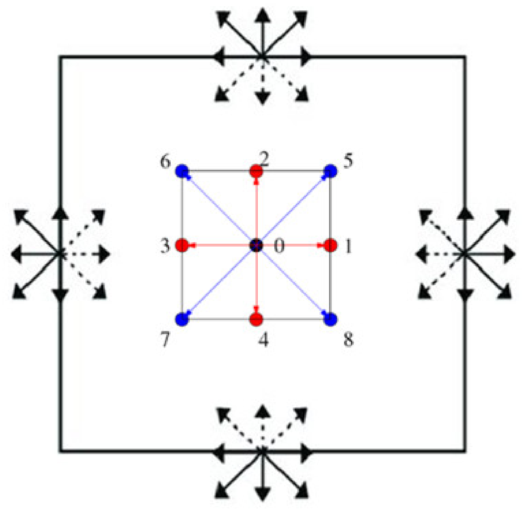
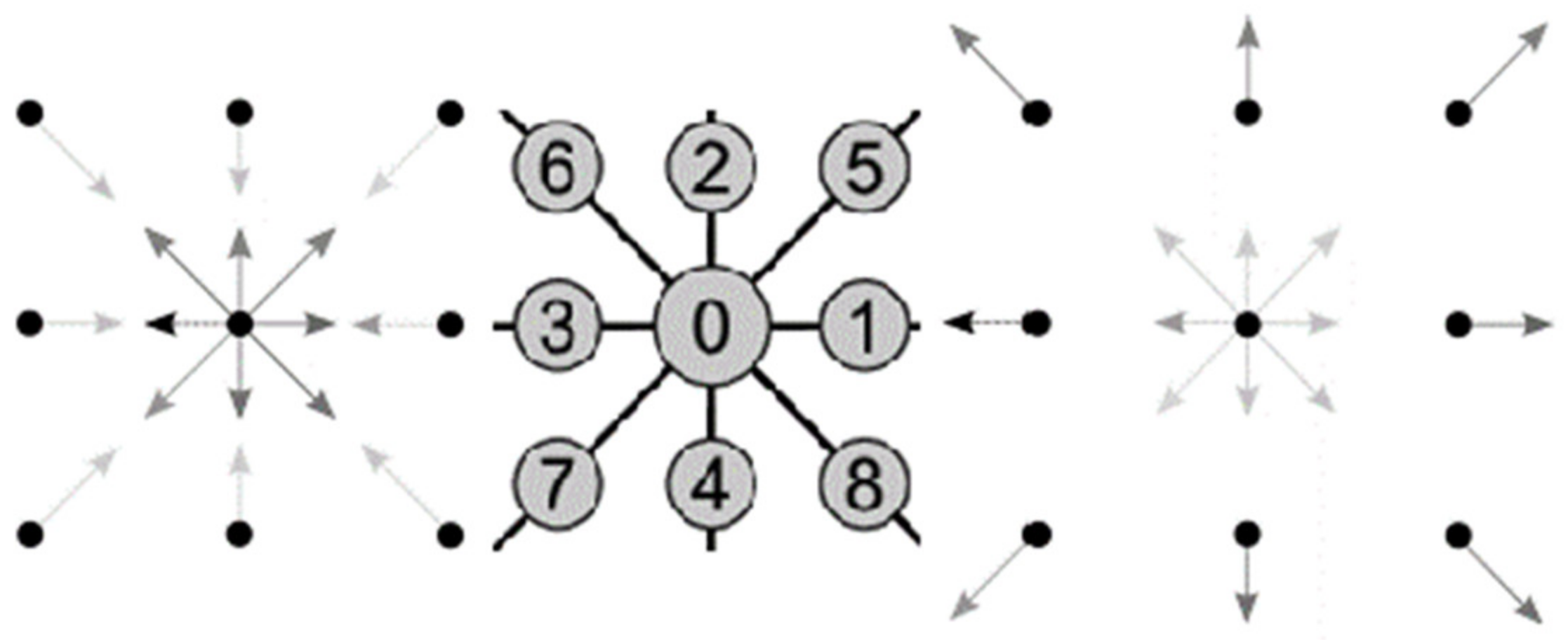
3. LBM Approach for Free Convection
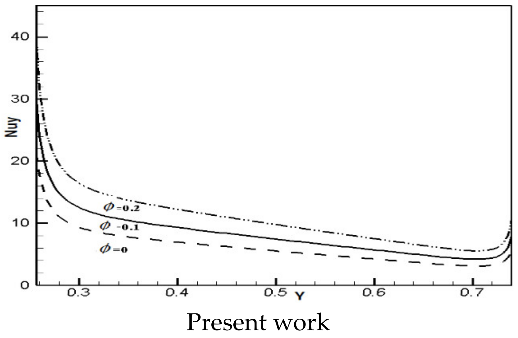
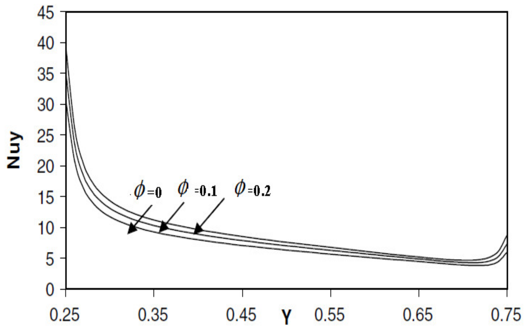
In the last decade, LBM has become a successful attractive numerical mesoscopic for many engineering heat-mass transfer associated with fluid flow simulations. The technical approach is based on two distribution functions (DF): f i for the flow field and g i for the temperature.
The flow field [11,12,13,14,15,16,17,18,19,20,21,22] in the presence of an external force F i is defined by distribution function (DF) f i for the flow field, which can be given as:
f i r + e i Δ t , t + Δ t = Δ t τ ν f i r , t f i 0 r , t + f i r , t + Δ t e i F i
where the LEDF (local equilibrium distribution function) flow field is:
f i e q = w i ρ 1 + e i . u c s 2 + ( e i . u ) 2 2 c s 4 e i . u 2 c s 2
Distribution function (DF) g i for the temperature ( θ ) field can be written as:
g i ( r + e i Δ t , t + Δ ) = ( 1 ( Δ t τ T ) )   g i ( r , t ) + ( Δ t τ T )       g i e q ( r , t )
The local equilibrium distribution function (LEDF) associated with the thermal field is computed as:
  g i e q =   w i ρ e   ( 1 + e i . u c s 2 )
We consider a unity lattice time step Δ t and nine discrete particle velocity vectors ei, expressed as (Figure 1):
e 0   =   0 , 0
e b   =   c o s ( ϕ b , s i n ( ϕ b ) ) . c   for   ϕ b = b 1 π / 2     b = 1 4  
e b = 2 c o s ( ϕ b , s i n ( ϕ b ) ) . c       for   ϕ b = b 5 π 2 + π     b = 5 8  
For the momentum equation, the relaxation time for the flow field τ v :
τ v = 0.5 + 3 ν / c 2 Δ t
where ν is the kinematic viscosity.
Defining α as the thermal diffusivity of the scalar field, the relaxation-time for the temperature τ T is computed as:
τ T = 0.5 + 3 α / c 2 Δ t
The external force term F i (for free convection) in Equation (17) is given by:
F i = w i c s 2 F . e i
We consider a unity lattice speed c = Δ x / Δ t related to sound lattice speed as c = 3 c s , and Δ x is the lattice-space. For simplicity, in this work, we neglect the inconsistency due to the fact that the viscosity ν has the expression τ f   R T in the heat dissipation, whereas it maintains the expression R T τ f 0.5 in Navier–Stokes equations. This inconsistency may be eliminated using a second order strategy when integrating the Boltzmann equation [23,24].
The D2Q9 model is used for weighting factor w b for temperature and flow, calculated with the following equations:
w b = 4 9
w b = 1 9     for   b = 1 4  
w b = 1 36   for   b = 5 8  
The velocity u, macroscopic density ρ , and temperature T are computed, respectively, as:
u r , t = i c i f i r , t / i f i r , t
ρ r , t = i f i r , t
Because temperature is associated with the internal energy e deduced from the state equation ( e   =   R T ), temperature is written as:
T ( r , t ) = ρ r , t e = i g i r , t
Based on Boussinesq approximation, the incompressible regime of free convection imposes a small characteristic velocity compared to and c s , the fluid speed of sound, and the a M a (Mach number) should not exceed M a = 0.3 .
With a known number of lattices in vertical direction ( m ), Rayleigh number ( R a ), Prandtl number, and M a (Mach number), the thermal diffusivity and viscosity are computed from:
v f = c s m M a P r 0.5 R a 0.5
The local Nusselt number is expressed as [10]:
N u = L h k f
where the heat transfer coefficient is:
h = q w T h T c
The thermal conductivity of the NF (nanofluid) is computed as:
k n f = q w T / X
The local Nusselt number along the LW (left wall) can be written as:
N u = k n f k f θ X X = 0
The average Nusselt number along the heat-source is deduced as:
N u ¯ = 1 L 0 L k n f k f θ X X = 0

4. Validation

In this paper, the numerical procedure used to resolve the dimensionless equations is instituted on the mesoscopic approach LBM (lattice Boltzmann method). The D2Q9 lattices have been applied in both dynamic and thermal cases. The numerical approach is implemented using a FORTRAN software. A grid independence test is made using the LBM with different sets of grids, and good agreement with the literature is found for (251 × 251) grids. Aiming to verify to verify the precision of the current numerical technique, validation findings are compared with reference [9].
For validation, the same geometry (Figure 3) used in the literature is highlighted. A numerical simulation is performed for a flow induced by buoyancy force, which is suggested to a partially constant heated enclosure, which is filled with copper and water nano-fluid with the mesoscopic approach model LBM. The Rayleigh number is taken as Ra = 105, while the Prandtl number is Pr = 6.2. These evaluations are offered obviously in Figure 4 in terms of local Nusselt number variation alongside the heated left boundary (Cu-H2O nanofluid) for different volume fraction ( ϕ ) at Ra = 105. Figure 4 demonstrates a very good concordance between the current results and references’ ones [9].
First, aiming to highlight the effect of the solid volume fraction on the dynamic and the thermal flow, we increased the volume fraction ( ϕ ) from 0 to 0.2 and chose the same geometry as reference [9]. Figure 5 illustrates the effects of the solid volume fraction on non-dimensional temperature in axial midline versus x position at a moderately high Rayleigh number (Ra = 105). As shown in this figure, the non-dimensional temperature in the axial midline versus x position increases as the solid volume fraction becomes higher.
Additionally, Figure 6 and Figure 7 display the steady state non dimensional dynamic and thermal profiles behaviors for five different volume fractions ( ϕ ) at Ra = 105, where non-dimensional isotherms, streamlines, pressure, horizontal velocities, vertical velocities, and velocity magnitudes are enhanced when ϕ from 0 to 0.6.
Next, left local Nusselt evolution versus vertical wall for different volume fraction ( ϕ ) in case 1 and at Ra = 105 is represented in Figure 8. As shown in this plot, it is found that the volume fraction is a parameter that can potentially increase thermal behavior inside the cavity.
We now examine the explicit effect of boundary condition choice on dynamic and thermal behavior of the present engineering problem. So, after applying a simple partial Dirichlet Boundary Condition (BC) (case 1), we aim, in this work, to study the effect of two new benchmarks of left partial boundary condition on the heat transfer and fluid flow behaviors. Linear (case 2) and sinusoidal (case 3) heated partial left boundary conditions are studied for selective parameters of Prandtl number, Rayleigh number, and solid volume fraction. It is to be noted that, for case3, we consider a sinusoidal excitation, where the phase shift φ 0 = 0 .
For constant, linear, and sinusoidal boundary conditions (case 1: Dirichlet constant BC, case 2: linear BC, case 3: sinusoidal BC), the variation of local Nusselt number along the central partially heated left boundary in the presence of copper–water nanofluid is illustrated in Figure 9 at Ra = 105 and volume fraction ϕ = 0 .
It can be perceived that the higher maximum of the left local Nusselt number is reached for a sinusoidal excitation. Moreover, the maximum of the left local Nusselt in the Dirichlet boundary increases slightly compared to linear boundary case. The obtained numerical results approve that a sinusoidal central partially heated left boundary enhances the rate of heat transfer, which is an aim sought in different widespread physical and engineering applications.
A quantitative study is presented in Figure 10, where steady state dynamic and thermal profiles behavior for the three cases of the partially thermalized left boundary conditions at volume fraction ϕ = 0 and Ra = 105 are highlighted. We notice that isotherms, streamlines, horizontal velocities, vertical velocities, velocity magnitudes, and pressures present the maximum values for the case of the sinusoidal central partially heated left boundary and the minimum values for the linear ones, which is in good concordance with previous results in Figure 9.
In this section, we introduce the constant linear boundary conditions (case 2: linear BC) via the variation of the left local Nusselt number along the central partially heated left boundary in the presence of copper-water nanofluid, which is illustrated in Figure 3 at Ra = 105 for five values of the volume fraction ( ϕ = 0 ). Based on the Figure 11, we notice that the heat transfer rate is also enhanced for the maximum value of the volume fraction imposed in the cavity. The quantitative study is highlighted in Figure 12 and Figure 13 where steady state (SS) dynamic and thermal profiles performance of the heated partially left boundary for different sketch of volume fraction at Ra = 105 is shown. Isotherms, streamlines, and pressure are shown in Figure 12, and horizontal velocities, vertical velocities, and velocity magnitudes are shown in Figure 13. An evolution in the thermal and the dynamic profiles can be easily observed, which play a noticeable role in the enhancement of the physics of the flow inside the enclosure, depending on the volume fraction value.
Next, Figure 14 shows the effect of the applied constant sinusoidal boundary condition on the flow and the heat rate in the cavity where the variation of local Nusselt number along the central partially heated left boundary in the presence of copper-water nanofluid is increased, for Ra = 105 at different volume fractions ( ϕ ).
For a better understanding of the dynamic and thermal physics of the flow inside the cavity in this case test, steady state isotherms, streamlines, and pressure are analyzed in Figure 15. Additionally, Figure 16 depicts the evolution of horizontal velocities, vertical velocities, and velocity magnitude in the enclosure filled with copper-water nanofluid and subjected to sinusoidal central partially heated left boundary thermal excitation.
It is very pertinent to scrutinize the dynamic and thermal behavior inside a given cavity for a local Nusselt number, isotherms, streamlines, pressure, horizontal velocities, vertical velocities, and velocity magnitude with a given parametric study.
Further to the aforementioned analysis, it is pertinent to investigate the variation of left local Nusselt number along the left boundary of the Cu-water nanofluid cavity for volume fraction ϕ = 0.1 (Figure 17) and volume fraction ϕ = 0.6 (Figure 18) in the third case (sinusoidal boundary condition) at Ra = 105.
As result, more heat enhancement is obtained with a maximum volume fraction value for a sinusoidal central partially heated left boundary thermal excitation.

5. Conclusions

The current work offered the numerical simulations of free convection heat transfer in a partially central heated left wall enclosure with a D2Q9 mesoscopic approach LBM. The remaining partial sides of the left wall are adiabatic. The cavity is filled with a copper waler nanofluid with a cold right wall and adiabatic bottom and top wall. The present study is validated by extensive research and good validation is reached. It is shown that the left local Nusselt number can be enhanced by the partially sinusoidal thermal boundary condition, where its maximum becomes fluctuant comparing to Dirichlet and linear cases. Besides quantitative results through isotherms, streamlines, horizontal velocities, vertical velocities, velocity magnitude, and pressure profiles illustrate maximum values for the sinusoidal central partially heated left boundary. The focal conclusion that the rate of heat transfer is very enhanced when a sinusoidal excitation is applied on the sinusoidal central partially heated left side. A given numerical result will serve as future processing simulating in different widespread physical and engineering applications.

Author Contributions

Software, R.C.; Supervision, A.D.; Writing – original draft, R.C., Data curation, A.J.; Formal analysis, R.C., A.K., R.R., A.D. All authors have read and agreed to the published version of the manuscript.

Funding

This research received no external funding.

Institutional Review Board Statement

In this research, there was not any part of the study involving humans or animals.

Informed Consent Statement

This study is not involving humans.

Data Availability Statement

This numerical research using an advanced and sophisticated software system.

Conflicts of Interest

The authors declare no conflict of interest.

References

  1. Khanafer, K.; Vafai, K.; Lightstone, M. Buoyancy-driven heat transfer enhancement in a two-dimensional enclosure utilizing nanofluid. Int. J. Heat Mass Transf. 2003, 46, 3639–3653. [Google Scholar] [CrossRef]
  2. Pourfattah, F.; Motamedian, M.; Sheikhzadeh, G.; Toghraie, D.; Akbari, O.A. The numerical investigation of angle of attack of inclined rectangular rib on the turbulent heat transfer of WaterAl2O3 nanofluid in a tube. Int. J. Mech. Sci. 2017, 131–132, 1106–1116. [Google Scholar] [CrossRef]
  3. Akbari, O.A.; Karimipour, A.; Toghraie, D.; Safaei, M.R.; Alipour, H.; Goodarzi, M.; Dahari, M. Investigation of rib’s height effect on heat transfer and flow parameters of laminar water–Al2O3 nanofluid in a two dimensional rib-microchannel. Appl. Math. Comput. 2016, 290, 135–153. [Google Scholar]
  4. Rezaei, O.; Akbari, O.A.; Marzban, A.; Toghraie, D.; Pourfattah, F.; Mashayekhi, R. The numerical investigation of heat transfer and pressure drop of turbulent flow in a triangular microchannel. Physica E 2017, 93, 179–189. [Google Scholar] [CrossRef]
  5. Karimipour, A.; Alipour, H.; Akbari, O.A.; Semiromi, D.T.; Esfe, M.H. Studying the effect of indentation on flow parameters and slow heat transfer of water-silver nano-fluid with varying volume fraction in a rectangular two-dimensional micro channel. Ind. J. Sci. Technol. 2016, 8, 51707. [Google Scholar] [CrossRef]
  6. Haddad, Z.; Oztop, H.F.; Abu-Nada, E.; Mataoui, A. A review on natural convective heat transfer of nanofluids. Renew. Sustain. Energy Rev. 2012, 16, 5363–5378. [Google Scholar] [CrossRef]
  7. Mashayekhi, R.; Khodabandeh, E.; Bahiraei, M.; Bahrami, L.; Toghraie, D.; Akbari, O.A. Application of a novel conical strip insert to improve the efficacy of water–Ag nanofluid for utilization in thermal systems: A two-phase simulation. Energy Convers. Manag. 2017, 151, 573–586. [Google Scholar] [CrossRef]
  8. Barnoon, P.; Toghraie, D. Numerical investigation of laminar flow and heat transfer of non-Newtonian nanofluid within a porous medium. Powder Tech. 2018, 325, 78–91. [Google Scholar] [CrossRef]
  9. Hakan, F.; Oztop, H.F.; Abu-Nada, E. Numerical study of natural convection in partially heated rectangular enclosures filled with nanofluids. Int. J. Heat Fluid Flow 2008, 29, 1326–1336. [Google Scholar]
  10. Mahmoodi, M.; Hashemi, S.M. Numerical study of natural convection of a nanofluid in C shaped enclosures. Int. J. Therm. Sci. 2012, 55, 76–89. [Google Scholar] [CrossRef]
  11. Guo, Z.; Zheng, C.; Shi, B. Discrete lattice effects on the forcing term in the lattice Boltzmann method. Phys. Rev. E 2002, 65, 046308. [Google Scholar] [CrossRef] [PubMed]
  12. Liu, Q.; He, Y.L. Lattice Boltzmann simulations of convection heat transfer in porous media. Phys. A Stat. Mech. Appl. 2017, 465, 742–753. [Google Scholar] [CrossRef]
  13. Chaabane, R.; Askri, F.; Ben Nasrallah, S. Parametric study of simultaneous transient conduction and radiation in a two-dimensional participating medium. Commun. Nonlinear Sci. Numer. Simul. 2011, 16, 4006–4020. [Google Scholar] [CrossRef]
  14. D’Orazio, A.; Karimipour, A.; Nezhad, A.H.; Shirani, E. Lattice Boltzmann Method with heat flux boundary condition applied to mixed convection in inclined lid driven cavity. Meccanica 2015, 50, 945–962. [Google Scholar] [CrossRef]
  15. Chaabane, R.; Askri, F.; Ben Nasrallah, S. Analysis of two-dimensional transient conduction-radiation problems in an anisotropically scattering participating enclosure using the lattice Boltzmann method and the control volume finite element method. J. Comput. Phys. Commun. 2011, 82, 1402–1413. [Google Scholar] [CrossRef]
  16. Goodarzi, M.; D’Orazio, A.; Keshavarzi, A.; Mousavi, S.; Karimipour, A. Develop the nano scale method of lattice Boltzmann to predict the fluid flow and heat transfer of air in the inclined lid driven cavity with a large heat source inside, Two case studies: Pure natural convection & mixed convection. Phys. A Stat. Mech. Appl. 2018, 509, 210–233. [Google Scholar]
  17. Chaabane, R.; Askri, F.; Ben Nasrallah, S. Application of the lattice Boltzmann method to transient conduction and radiation heat transfer in cylindrical media. J. Quant. Spectrosc. Radiat. Transf. 2011, 112, 2013–2027. [Google Scholar] [CrossRef]
  18. D’Orazio, A.; Nikkhah, Z.; Karimipour, A. Simulation of copper–water nanofluid in a microchannel in slip flow regime using the lattice Boltzmann method with heat flux boundary condition. J. Phys. Conf. Ser. 2015, 655, 012029. [Google Scholar] [CrossRef]
  19. Chaabane, R.; Askri, F.; Jemni, A.; Nasrallah, B.S. Numerical study of transient convection with volumetric radiation using an hybrid lattice Boltzmann BGK-control volume finite element method. J. Heat Transf. 2017, 139, 092701. [Google Scholar] [CrossRef]
  20. D’Orazio, A.; Karimipour, A. A useful case study to develop lattice Boltzmann method performance: Gravity effects on slip velocity and temperature profiles of an air flow inside a microchannel under a constant heat flux boundary condition. Int. J. Heat Mass Transf. 2019, 136, 1017–1029. [Google Scholar] [CrossRef]
  21. Chaabane, R.; Askri, F.; Jemni, A.; Nasrallah, B.S. Analysis of Rayleigh-Bénard Convection with thermal volumetric radiation using Lattice Boltzmann Formulation. J. Therm. Sci. Technol. 2017, 12, JTST0020. [Google Scholar] [CrossRef] [Green Version]
  22. Hinojosa, J.F.; Cabanillas, R.E.; Alvarez, G.; Estrada, C.E. Nusselt number for the natural convection and surface thermal radiation in a square tilted open cavity. Int. Commun. Heat Mass Transfer. 2005, 32, 1184–1192. [Google Scholar] [CrossRef]
  23. D’Orazio, A.; Succi, S.; Arrighetti, C. Lattice Boltzmann simulation of open flows with heat transfer. Phys. Fluids 2003, 15, 2778–2781. [Google Scholar] [CrossRef]
  24. He, X.; Chen, S.; Doolen, G. A Novel Thermal Model for the Lattice Boltzmann Method in Incompressible Limit. J. Comp. Phys. 1198, 146, 282–300. [Google Scholar] [CrossRef]
  25. Haghshenas, A.; Rafati Nasr, M.; Rahimian, M.H. Numerical simulation of natural convection in an open-ended square cavity filled with porous medium by lattice Boltzmann method. Int. Commun. Heat Mass Transf. 2010, 37, 1513–1519. [Google Scholar] [CrossRef]
Figure 1. BGK D2Q9 LBM basic lattice and known and unknown populations in the computational domain.
Energies 14 06448 g001
Figure 2. Propagation step in a D2Q9 square boundary lattice Boltzmann model geometry.
Energies 14 06448 g002
Figure 3. Geometrical configuration.
Energies 14 06448 g003
Figure 4. Variation of the left local Nusselt number variation alongside the heated left boundary (Cu-H2O nanofluid) for different volume fractions ( ϕ ) at Ra = 105 [9].
Energies 14 06448 g004aEnergies 14 06448 g004b
Figure 5. Non-dimensional temperature in axial midline versus x position for different volume fractions ( ϕ ) for Ra = 105.
Energies 14 06448 g005
Figure 6. Steady state non-dimensional isotherm, streamline, and pressure profile behavior for central partially left boundary conditions (case 1: Dirichlet constant boundary condition) at different volume fractions ( ϕ ) for Ra = 105.
Energies 14 06448 g006
Figure 7. Steady state non-dimensional X-velocity, Y-velocity, and velocity magnitude profile behavior for central partially left boundary conditions (case 1: Dirichlet constant boundary condition) at different volume fractions ( ϕ ) for Ra = 105.
Energies 14 06448 g007
Figure 8. Variation of left local Nusselt number along the left boundary (Cu-water nanofluid) for different volume fractions ( ϕ ) (case 1) at Ra = 105.
Energies 14 06448 g008
Figure 9. Variation of left local Nusselt number along the central partially heated left boundary (Cu-water nanofluid) for different left wall BCs (Boundary Conditions) (case 1: Dirichlet constant BC, case 2: linear BC, case 3: sinusoidal BC) at Ra = 105 and volume fraction ϕ = 0 .
Energies 14 06448 g009
Figure 10. Steady state non-dimensional dynamic and thermal profiles behavior for different partially left boundary conditions at volume fraction ϕ and Ra = 105.
Energies 14 06448 g010aEnergies 14 06448 g010b
Figure 11. Variation of left local Nusselt number along the left boundary (Cu-water nanofluid) for different volume fraction ϕ (case 2: linear boundary condition) at Ra = 105.
Energies 14 06448 g011
Figure 12. Steady state non-dimensional isotherm, streamline, and pressure profile behavior for central partially left boundary conditions (case 2: linear boundary condition) at different volume fractions ( ϕ ) for Ra = 105.
Energies 14 06448 g012
Figure 13. Steady state non-dimensional X-velocity, Y-velocity, and velocity magnitude profiles behavior for central partially left boundary conditions (case 2: linear boundary condition) at different volume fractions ( ϕ ) for Ra = 105.
Energies 14 06448 g013
Figure 14. Variation of left local Nusselt number along the left boundary (Cu-water nanofluid) for different volume fractions ( ϕ ) (case 3: Sinusoidal boundary condition) at Ra = 105.
Energies 14 06448 g014
Figure 15. Steady state isotherm, streamline, and pressure profile behavior for central partially left boundary conditions (case 3: sinusoidal boundary condition) at different volume fractions ( ϕ ) for Ra = 105.
Energies 14 06448 g015
Figure 16. Steady state X-velocity, Y-velocity, and velocity magnitude profiles behavior for central partially left boundary conditions (case 3: sinusoidal boundary condition) at different volume fractions ( ϕ ) for Ra = 105.
Energies 14 06448 g016
Figure 17. Variation of local Nusselt number along the central partially heated left boundary (Cu-water nanofluid) for different left wall Bcs (boundary conditions) (case 1: Dirichlet constant BC, case 2: linear BC, case 3: sinusoidal boundary condition) at Ra = 105 at volume fraction ϕ = 0.1 .
Energies 14 06448 g017
Figure 18. Variation of local Nusselt number along the central partially heated left boundary (Cu-water nanofluid) for different left wall Bcs (boundary conditions) (case 1: Dirichlet constant boundary condition, case 2: linear boundary condition, case 3: Sinusoidal boundary condition) at Ra = 105 and volume fraction ϕ = 0.6 .
Energies 14 06448 g018
Table 1. Thermo-physical (TH) properties of BF (base fluid) and copper of nanoparticles (NPs).
PropertiesWater
Fluid Phase
Cu (Copper)
Solid Phase
Cp (J/(kg·k))4179385
Density (kg/m3)997.18933
K (W/mK)0.613401
β × 105 (1/K)211.67
Publisher’s Note: MDPI stays neutral with regard to jurisdictional claims in published maps and institutional affiliations.

