1. Introduction
Due to the abundant sources and advanced power generation technologies, the wind power is integrated into the grid on a large scale as a major green source. Currently, the low voltage ride through (LVRT) is one of the most important issues to the modern systems with high penetration of wind power. To overcome this difficulty, the grid-connected requirements for wind power have become stricter and stricter. The grid codes enforce the wind turbine generator (WTG) to keep grid-connected and provide reactive power support under faults.
At present, the doubly fed induction generator (DFIG) [
1,
2,
3,
4,
5,
6] and the permanent magnet synchronous generator (PMSG) [
7,
8,
9,
10,
11,
12] are two mainstream wind turbine generators (WTGs). On the one hand, the PMSG exempts the gearbox, which is easily broken, so as to reduce maintenance cost and improve the reliability of PMSG; on the other hand, the PMSG can complete isolation from the grid disturbances owing to the full-scale converter. In comparison with DFIG, the PMSG has a simpler structure, lower maintenance cost and higher LVRT capabilities [
13].
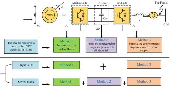
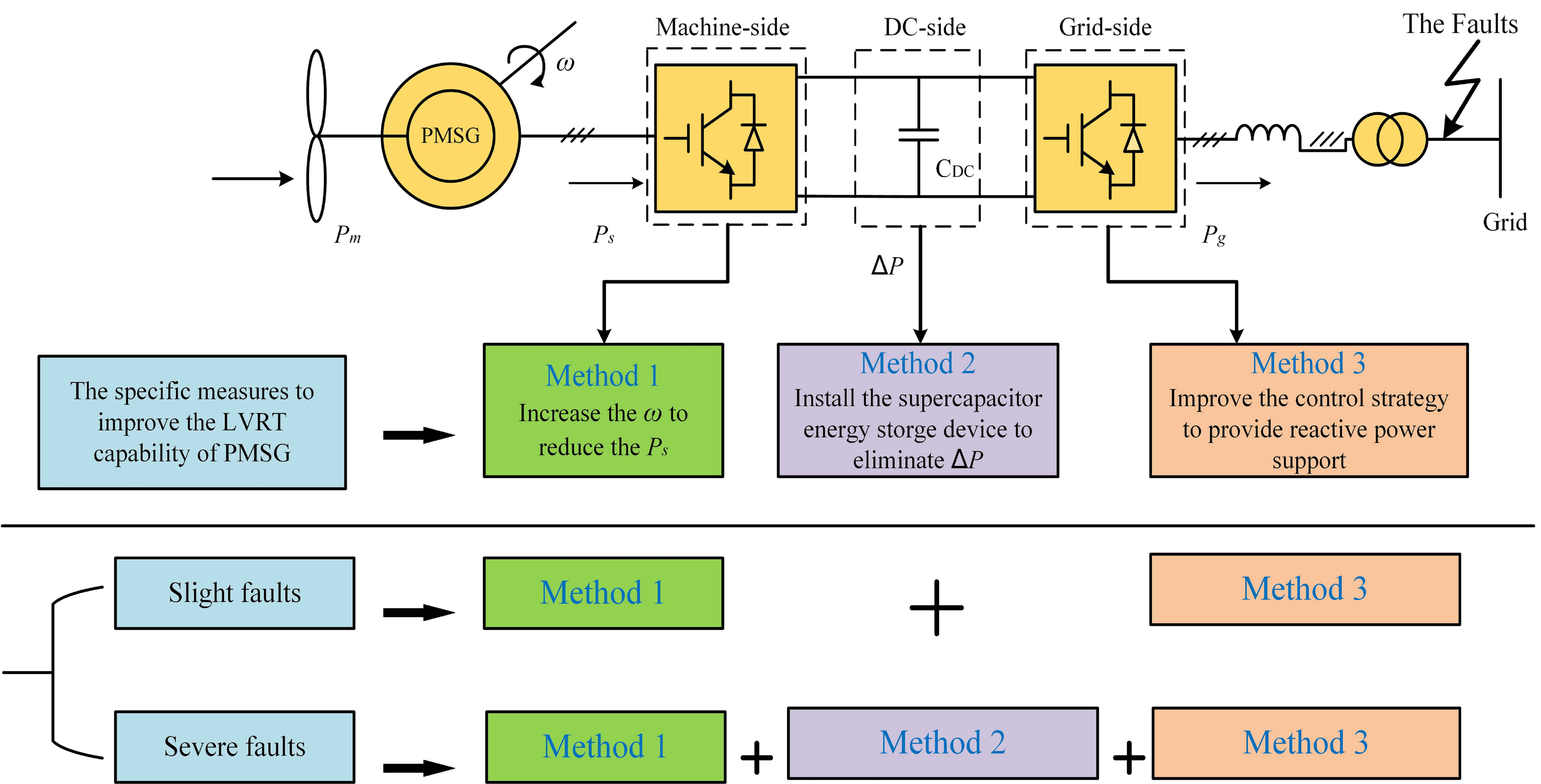
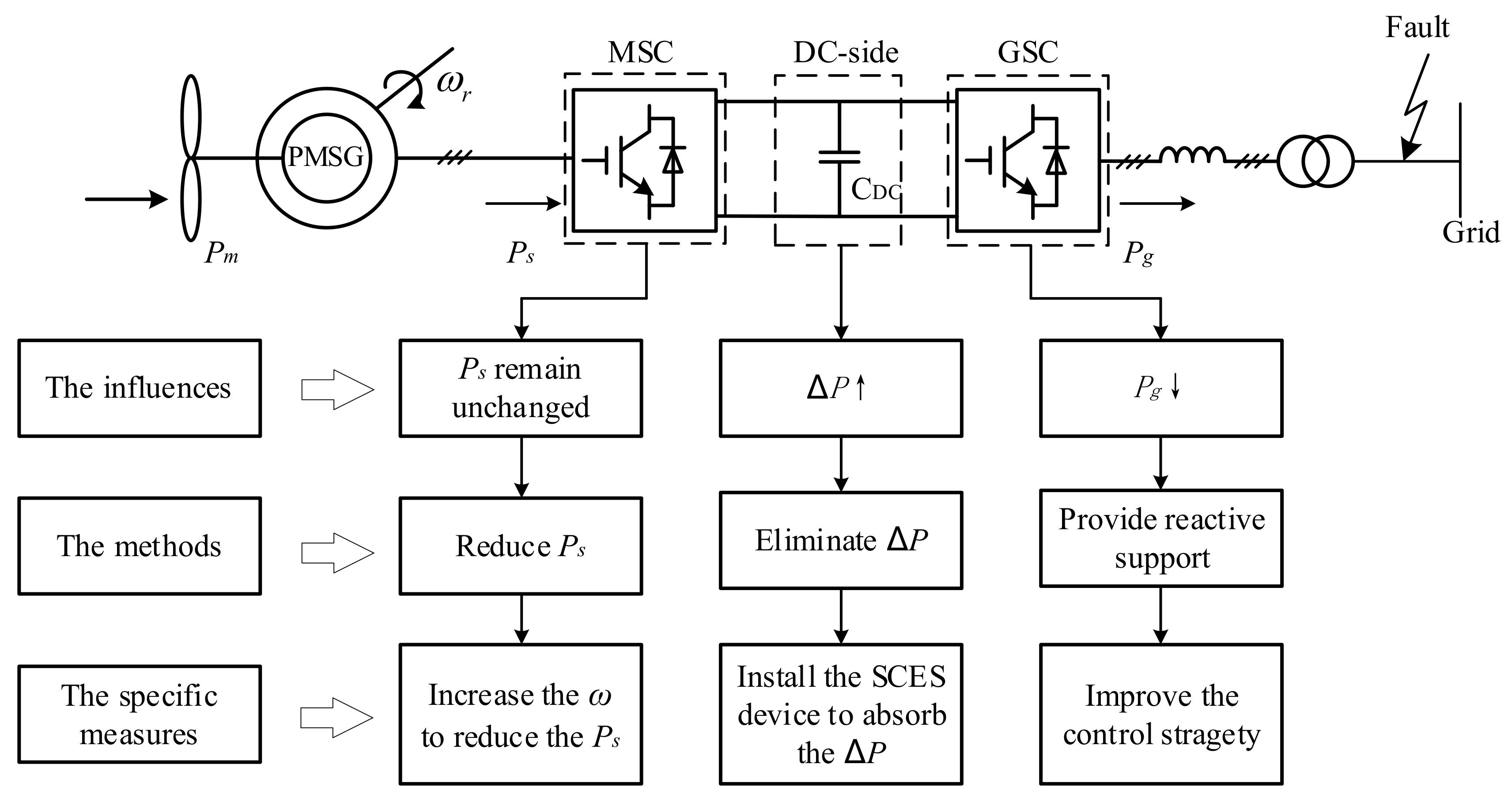
Recently, the methods of the LVRT enhancement of PMSG have been divided into two primary types: inherent control modification and auxiliary device modification [
14]. The inherent control modification was well covered in the following references [
15,
16,
17,
18,
19,
20]. The active power surplus was stored in the inertia of the turbine–generator system to keep the DC-link voltage stability in [
15,
16,
17]. Moreover, in [
16], a direct model predictive control is proposed for enhancing the dynamic response of the wind energy conversion systems. In addition, the control strategies of stator-side and grid-side were altered to provide reactive power for the grid under faults in [
17]. Then, a new control structure is presented in [
18,
19], the machine-side converter (MSC) was utilized to regulate the DC-link voltage, while the grid-side converter (GSC) was used for fulfilling the maximum power point tracking (MPPT) of the wind turbine. Accordingly, when the voltage sags in the grid-side, the active power generated by the PMSG can be reduced, hence the surplus power of DC-side is decreased. Then, the voltage of DC-side is easily able to be stable. However, the performance of the control scheme in [
18,
19] is inaccurate in the normal condition. In [
20], the pitch control was used to reduce the available wind power, and the excess energy is stored by the rotor and the DC-link capacitor. Moreover, the reactive power support was provided by the GSC. Whereas, the pitch control is a slow mechanical process and it cannot respond to the disturbances of system immediately. What is more, frequent change of the pitch angle results in the abrasion of equipment and the decrease of PMSG lifetime.
In addition, the studies on auxiliary device modification are also attention-attracting for its characteristics of a fast response and wide adjustable range under different levels of voltage sags. In [
21,
22], the excess energy of DC side was dissipated by the chopper circuit to avoid the overvoltage of the DC side and eliminate the mismatch between the input power of MSC and the output power of GSC. The method is utilized widely for its simple control strategy and low costs. However, it is noteworthy that the efficiency of PMSG is declining owing to the waste of energy, and the overheating problem occurs under severe faults. In [
23], as a multiple-functional flexible alternating current transmission system (FACTS) device, the electronic power transformer (EPT) was combined with energy storage system to enhance the LVRT capability of PMSG. In [
24], the supercapacitor energy storage (SCES) devices were installed on the DC-side, and they can absorb the surplus active power of DC-side to prevent the DC link capacitor from overvoltage. The effectiveness of the SCES is verified comparing with conventional current-limiting strategy. However, there was no specific capacity configuration scheme of the SCES in [
24]. The superconducting magnetic energy storage (SMES) was presented in [
25] to improve the LVRT capability and transient stability of PMSG, the superconducting fault current limiter (SFCL) was utilized to increase the output power of GSC, while the excess power was absorbed by the SMES so as to reduce its energy storage capacity.
In brief, the inherent control modification reduces the input power at the cost of the increasing mechanical tensions and faster aging, while the auxiliary device modification dissipates or absorbs the surplus power to prevent the DC capacitor from overvoltage at the expense of economic performance. In order to take full advantages of the two types of methods, based on the SCES control in [
24], this paper presents a novel coordinated control scheme of rotor overspeed control and supercapacitor energy storage (SCES) control for PMSG-based WTG to improve the LVRT performance with comprehensive consideration of many factors. In this paper, the rotor speed is increased within allowable limits to reduce the input power of MSC under slight faults, and the rotor speed is set to the upper-limit to reduce the input power of MSC to the maximum extent under severe faults. The SCES is inoperative under slight faults to prevent the SCES from switching frequently, but the SCES can absorb the excess energy to prevent the DC link capacitor from overvoltage under severe faults. The specific capacity of the SCES is calculated, compared and verified. In addition, the GSC is utilized to maintain the DC voltage stability under the normal condition and provide reactive power support under faults.
The rest of this paper is structured as follows: The grid codes and technical principle of LVRT are introduced in detail in
Section 2. The rotor overspeed control scheme of PMSG-based WTG is described in
Section 3. The SCES control scheme is given in
Section 4. The two kinds of coordinated control scheme for PMSG-based WTG are presented in
Section 5. The simulation results and analyses of the proposed coordinated control scheme are shown in
Section 6. Finally, the conclusions are drawn in
Section 7.
3. The Overspeed Control Scheme
The mechanical power captured by the wind turbine can be described as Equation (2):
where
ρ is the air density,
R is the radius of the wind turbine blade,
V is the wind speed, and
Cp is the wind power coefficient [
27], which is the function of the tip speed radio
λ and the pitch angle
β. Generally, in order to maximize the use of wind energy, the
Cp is set to maximum value
Cpmax, and tip speed radio
λ is set to the optimal value
λopt:
where
λ is given as Equation (5).
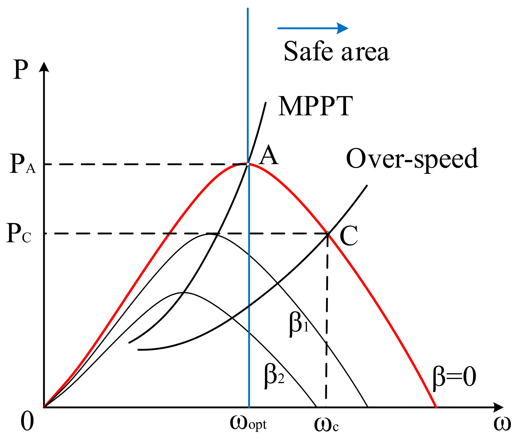
It is assumed that the wind speed
V is constant during the short time interval for the electromagnetic transient analysis. In addition, we did not take the pitch control into account due to its slow mechanical response. Therefore, the wind speed
V was set to
VN (i.e.,
V =
VN), and the pitch angle
β was set to 0 (i.e.,
β = 0). According to Equations (2)–(5), the input power curve is shown as
Figure 3:
The unbalance power of the DC-side produced by the mismatch between the input power and the output power during faults can be expressed as:
Thus, to eliminate the mismatch between the input power of MSC
Ps and the output power of GSC
Pg, the input power
Ps needs to be reduced by Δ
P. Then the deloading rate is defined as
d = Δ
P/PA, where
PA is the maximum power captured by the wind turbine in the MPPT mode. Due to the static instability problem caused by under-speed control [
28], then overspeed control is generally adopted to keep the rotor working in the safe area (i.e., the right area of the optimal speed
ωopt) [
29]. The power of the overspeed point
PC can be represented as:
The wind power coefficient of the overspeed point can be expressed as:
Under the condition of
β = 0,
Cp is given according to Equation (8), and then
λ can be obtained by Equations (3) and (4). Furthermore, the rotor speed reference ω
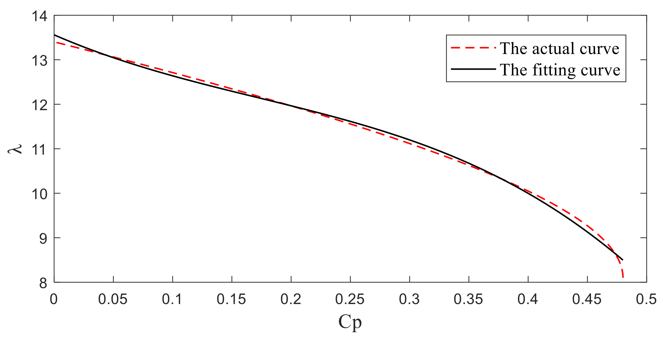
ref can be calculated easily according to Equation (5). However, consider the strong nonlinearity of the
Cp-
λ curve, it is hard to find the concrete expression of inverse function of
Cp = f(λ). To address this issue, in this paper, the least square method is was to fit the inverse function of
Cp = f(λ).When the order of polynomial
n = 3, the equation is shown as:
Comparing with the actual curve, the fitting curve with the allowable errors is shown in
Figure 4.
The overspeed control strategy of MSC is shown in
Figure 5. The outer loop is the speed control loop while the inner loop is the current control loop. The
d axis current reference
idref is set to 0 both in the steady state and faulted state, while the
q axis outer speed reference
ωref switches between the normal mode and faulted mode according to the state of the system. When the system is steady, the switch is work at Mode 1, the speed reference
ωref is set to
ωopt (i.e.,
ωref =
ωopt), the PMSG is working at point A, the input power of MSC is equivalent to the maximum mechanical power captured by the wind turbine
PA. When the voltage sags, the switch is working at Mode 2, the speed reference
ωref is set to
ωc. The reference control variables of the MSC are altered so as to reduce the input power, and eliminate the mismatch between the input power and the output power.
According to
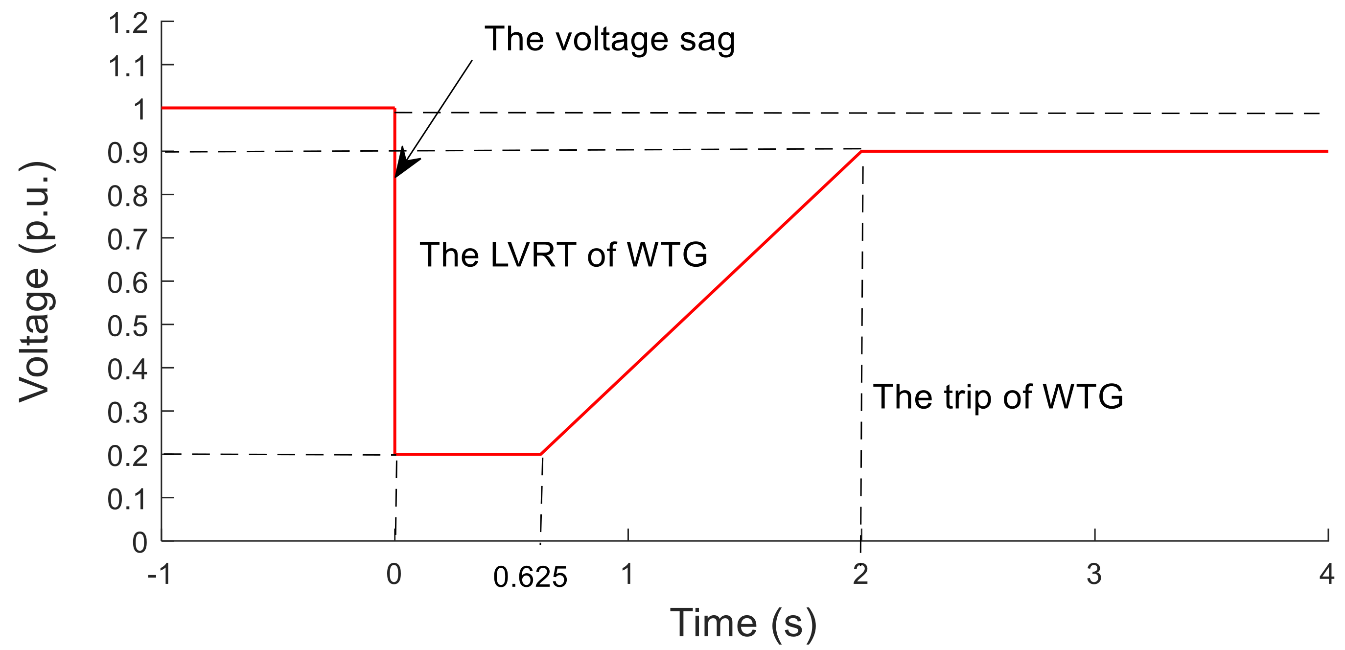
Figure 1, under the symmetrical fault (i.e., the worst case of voltage sags), the unbalanced energy generated during faults can be expressed as:
where the integral time
t means the time that PMSG keeps connected to the grid under faults, and Δ
P is the deviation between the output power during faults and the rated power.
The unbalanced power is generated due to the voltage sags and current limiting measures of GSC. Thus, the output current is keeping at the upper limit under voltage sags, that is to say, the current is constant during faults. Consequently, the output power Pg is proportional to the grid voltage ug.
By substituting the data of
Figure 1 into Equation (11) [
30], the unbalanced energy generated during faults can be calculated as:
where
PN is the rated power of PMSG. The total unbalance energy of the DC-side is 28 kJ in the worst case of voltage sags. Hence, to eliminating the unbalanced energy 28 kJ within 2 s, the average changed power by regulating the rotor is 14 W, and the corresponding speed is
according to
Figure 3. However, the rotor speed of the wind turbine, generally, should not exceed 1.2
ωN [
31]. Thus, the deloading rate
d should keep between 0 and 12% without the pitch control.
The rotor overspeed control scheme can enhance the inherent LVRT performance of PMSG by regulating the rotor speed without auxiliary devices. Apparently, the advantage of the overspeed control is low cost. However, the rotor overspeed control scheme is only applicable to the condition of slight faults due to the limit of maximum rotor speed.
4. The Supercapacitor Energy Storage (SCES) Control Scheme
To cope with the issue existing in the rotor overspeed control scheme, the SCES control scheme is proposed to improve the LVRT capability of PMSG under all conditions of voltage sags [
24].
The unbalanced power on the DC-side under faults leads to overvoltage as the following:
To maintain the stability of DC voltage during faults, the energy storage systems, which consist of the SCES and the bidirectional DC–DC converter, are installed on the DC-side. In comparison with other energy storage, the SCES is more attractive and suitable for LVRT occasions owing to its higher power density, more cycle times, and shorter charge–discharge time. Consequently, The SCES is selected to store or release the energy in this paper.
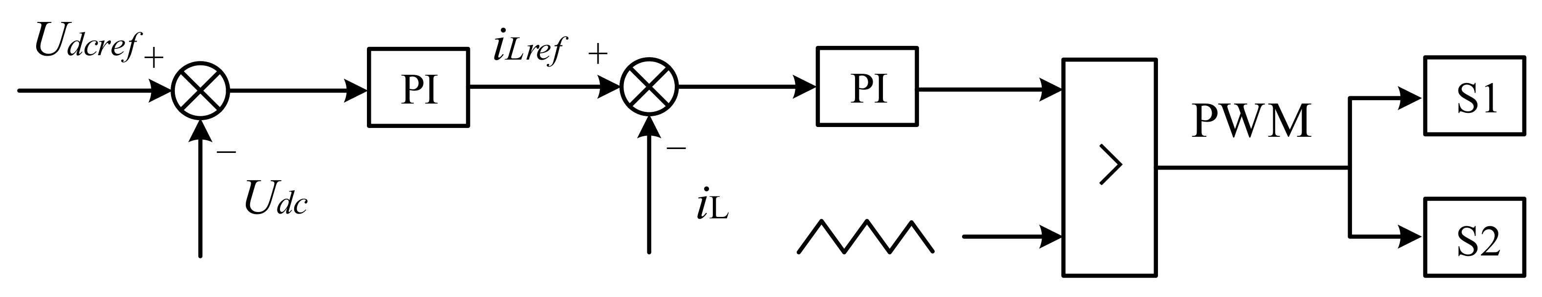
In addition, the bidirectional DC–DC converter is mainly used to fulfill the charge–discharge control of the SCES and improve the stability of DC voltage. If the DC voltage rises, the bidirectional DC–DC converter works at the buck mode. Otherwise, the bidirectional DC–DC converter works at the boost mode.
Thus, the control strategy of the bidirectional DC–DC converter is displayed in
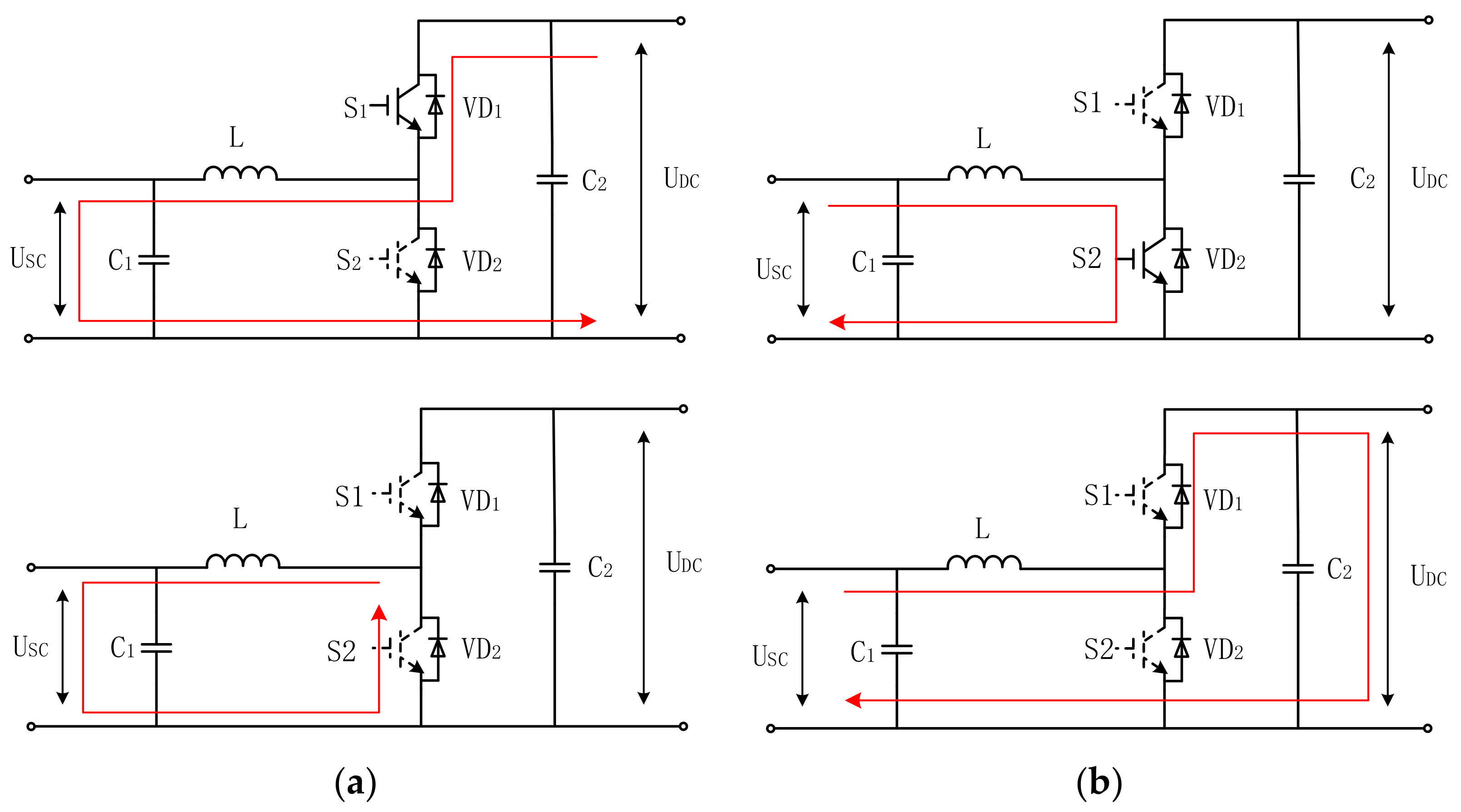
Figure 6. The voltage control outer loop achieves the voltage stability by tracking DC voltage, while the current control inner loop improves the response speed. Furthermore, the working mode of the bidirectional DC–DC converter is shown in the
Figure 7, when the S1 is triggered, the converter works in the buck mode and the SCES absorbs the energy from the DC-side; when the S2 is triggered, the converter works in the boost mode and the SCES transfers the stored energy to the DC link. It should be noted that S1 and S2 cannot be triggered concurrently.
In practice, consider the impacts of the series equivalent resistance of the SCES, the losses caused by the large number of supercapacitors integrated in series or in parallel, and the possibility of grid faults occurring multiple times during a period of time. Thus, the actual capacity of the SCES should be multiplied by a larger reliability coefficient based on the theoretical value. In addition, the SCES usually works at a middle voltage
U0 so as to charge or discharge. In this paper, we set the reliability coefficient of unidirectional energy transmission to 1.5, and then the reliability coefficient of bidirectional energy transmission was set to 3 [
30]. According to Equation (12), the theoretical value of unbalanced energy is 28 kJ. Therefore, the triple energy of SCES (i.e., 84 kJ) should be configured in this paper.
This paper adopted the single supercapacitor and the specifications were:
Cs = 300 F,
Us = 2.5 V and
Rs = 200 mΩ. Then 120 supercapacitors were connected in series to form the SCES. Here, define discharge depth
h =
Umin/Umax, and the energy absorbed or released by the SCES can be described as:
The state of charge (SOC) of the SCES can be expressed as:
Generally, the discharge depth was set to 50% (i.e., h = 50%), then the SOC of SCES was calculated between 25 and 100%, and the chargeable and dischargeable energy of the SCES was 75%. Apparently, the utilization rate of the SCES was relatively high.
From Equation (14), the maximum energy absorbed by the SCES can be calculated as follows:
Thus, the value meets the requirement of reliability coefficient. In addition, the initial middle voltage
U0 of the SCES can be obtained from Equation (17) [
32]:
Therefore, the SCES control scheme is applicative under the all conditions of voltage sags as long as the capacity configuration is appropriate. However, the separate utilization of the SCES control scheme is not conducive to the economic performance of the system owing to its high cost.
5. The Coordinated Control of Rotor Overspeed and SCES
According to the aforementioned control scheme in
Section 3, the rotor overspeed control scheme under severe faults is prone to result in the rotor speed of the PMSG out-of-limit and affects the safety and stability of the power system. Additionally, in
Section 4, the cost for separate utilization of the SCES control is high.
Thus, in order to take the advantages of the rotor overspeed control and the SCES control, and overcome drawbacks of either of the two control methods, now we are in a position to propose the coordinated control strategies, in which two innovative schemes are discussed as follows.
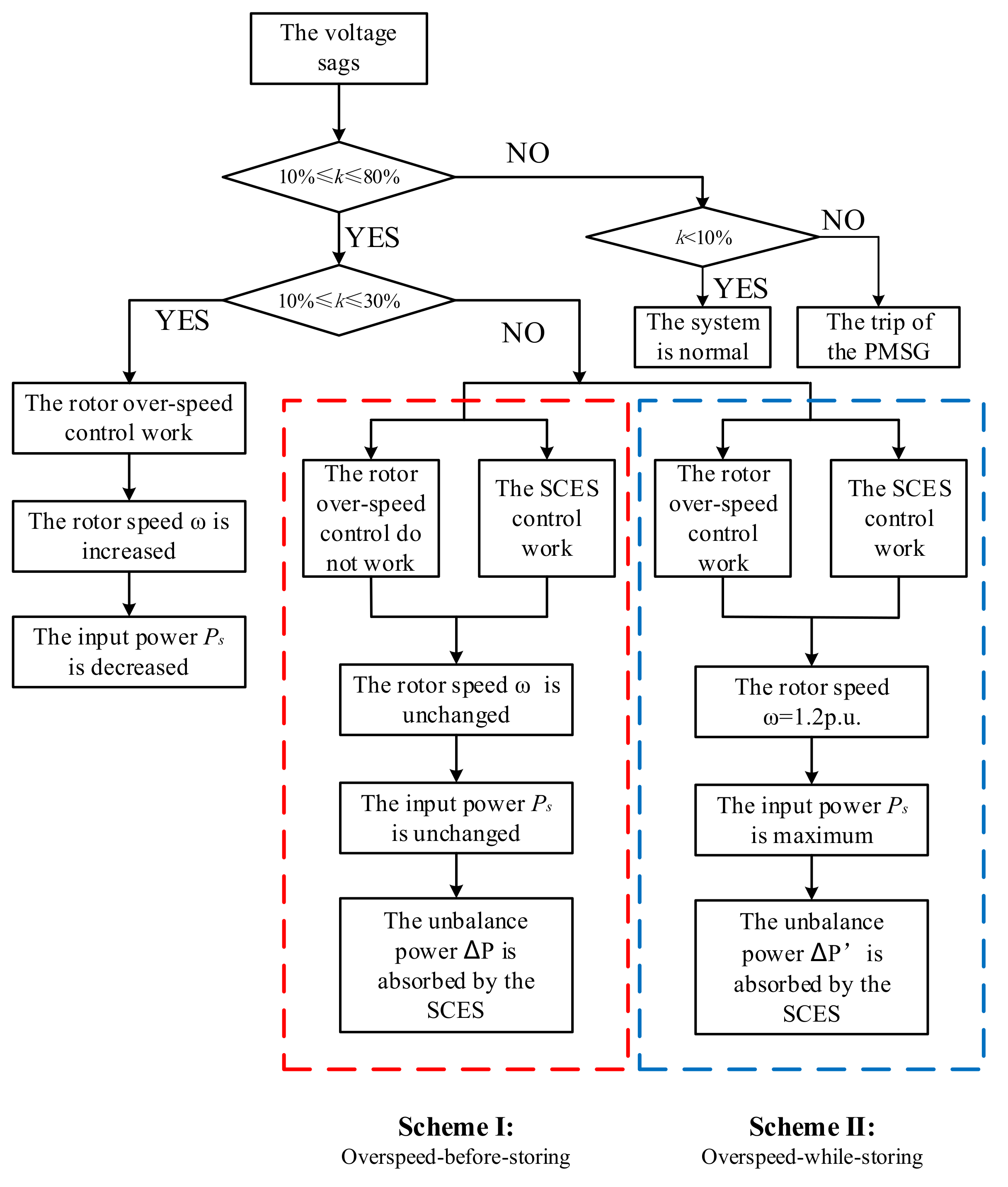
5.1. Coordinated Control Scheme I: Overspeed-Before-Storing
A reliable and effective coordinated control scheme named overspeed-before-storing is proposed (i.e., Scheme Ⅰ). The rotor overspeed control is adopted under the slight faults; while the SCES control is adopted under the severe faults.
Introduce the voltage sag depth k = ΔU/UN. Noteworthily, when k is equal to 30%, the rotor speed is up to the upper bound limit (i.e., 1.2 p.u.). Therefore, we set the critical value as 30% to avoid the rotor speed out-of-limit.
The control strategy of Scheme Ⅰ is as follows: When the voltage sag depth
k ≤ 30%, the rotor overspeed control is adopted. Contrarily, the SCES control is adopted. The specific control flow chart is shown in
Figure 8.
Theoretically speaking, Scheme Ⅰ can fulfill the LVRT requirements of PMSG under the all voltage sags conditions. Furthermore, Scheme Ⅰ can avoid frequent switching of SCES under slight faults. Whereas, in Scheme Ⅰ, the capacity configuration of SCES is the same as the SCES control scheme in
Section 4, and the economic performance of the system is not improved.
5.2. Coordinated Control Scheme II: Overspeed-While-Storing
Based on further optimization and improvement of Scheme Ⅰ, the coordinated control scheme named overspeed-while-storing (i.e., Scheme II) is presented. When the voltage sag depth
k ≤ 30%, the rotor overspeed control scheme was adopted, and it was the same as in the Scheme Ⅰ. However, if
k > 30%, unlike Scheme Ⅰ, the rotor overspeed control and the SCES control worked together. The rotor angular speed increased and maintained at maximum (i.e.,
ω = 1.2 p.u.), and the surplus energy was absorbed by the SCES to stabilize the DC-side voltage. The detailed control flow chart is represented in
Figure 8.
In Scheme II, the unbalance power of DC-side under the severe faults is given as:
where Δ
P is the unbalance power between MSC and GSC without rotor overspeed control, and Δ
Ps is the variable quantity of input power by setting the rotor speed to maximum.
Substitute (18) into Equations (11) and (12), it can be calculated that the total unbalance power of DC-side under voltage sags is 23 kJ. To absorb the excess energy, the 100 supercapacitors are installed in series to form the SCES.
The maximum energy absorbed by the SCES is calculated as:
In practice, consider the limit of voltage transformation range of the DC–DC converter, the bound limits of voltage magnitudes on the SCES can be designed between 195 and 584 V [
33], that is, the corresponding voltage transformation ratio is between 0.25 and 0.75. Consequently, the maximum working voltage of the SCES meets the requirements under the three control schemes (i.e., the SCES control scheme, the coordinated control Scheme Ⅰ and Scheme II).
Comparing with the other three control schemes mentioned above, the coordinated control Scheme II could enhance the LVRT capability under the all conditions of voltage sags. Meanwhile, the rotor speed could stay in the safe limit. In addition, due to the impact of the regulation of rotor speed, the capacity configuration of SCES in coordinated control Scheme II is smaller than that in the SCES control scheme. In conclusion, the coordinated control Scheme II improves the stability and economy of the system simultaneously.
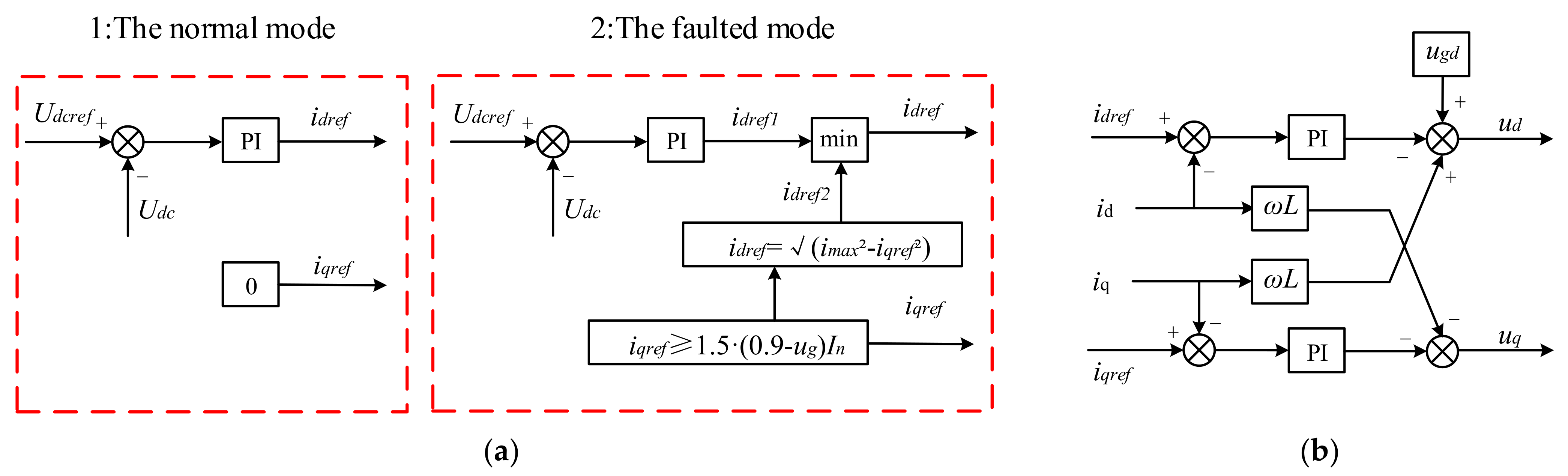
For all of the four control schemes mentioned above, the control strategy of the GSC is identical and it is presented as follows:
In the normal condition, the GSC works at the unity power factor mode (i.e., iqref = 0), in other words, there is no reactive power injected to the grid.
When the voltage sags, the reactive current reference can be written as:
where
ug is the grid voltage and
IN is the rated current. According to Equation (20), instead of the unity power factor control, the GSC is utilized to provide reactive power support, in other words, the GSC is set to the Q-priority mode [
34]. Accordingly, the active current should be limited by Equation (21) during faults because of the current limit of GSC, and the active current reference adopts the smaller one between
idref1 and
idref2. The reference control variables of the GSC are altered so as to provide reactive support to the grid under faults. The control strategy of GSC is shown in
Figure 9.
6. Simulation Validation
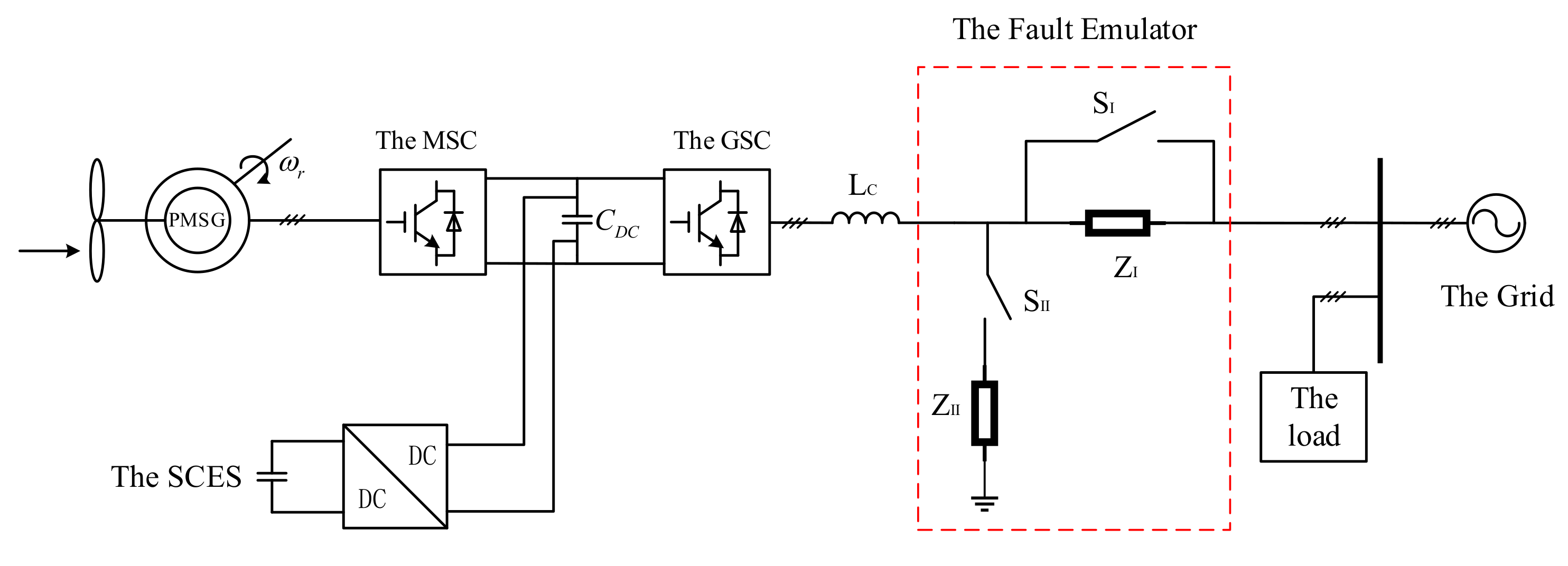
The simplified modeling of the grid-connected wind system in MATLAB/Simulink is depicted in
Figure 10. The wind system consists of a PMSG-base WTG, the MSC, the GSC, the SCES and the bidirectional DC–DC converter. The parameters of the modeling are listed in
Table 1.
The parameters of the below simulation analysis diagram are as follows: ua is the grid voltage, ω is the rotor angular speed, Ps is the input power of MSC, Udc is the DC-side voltage, Pg is the output power of GSC, Q is the reactive power generated by the GSC, Usc is the voltage of the SCES and SOC is the state of charge of the SCES.
6.1. The Simulation Results of the Four Control Scheme under Symmetrical Faults
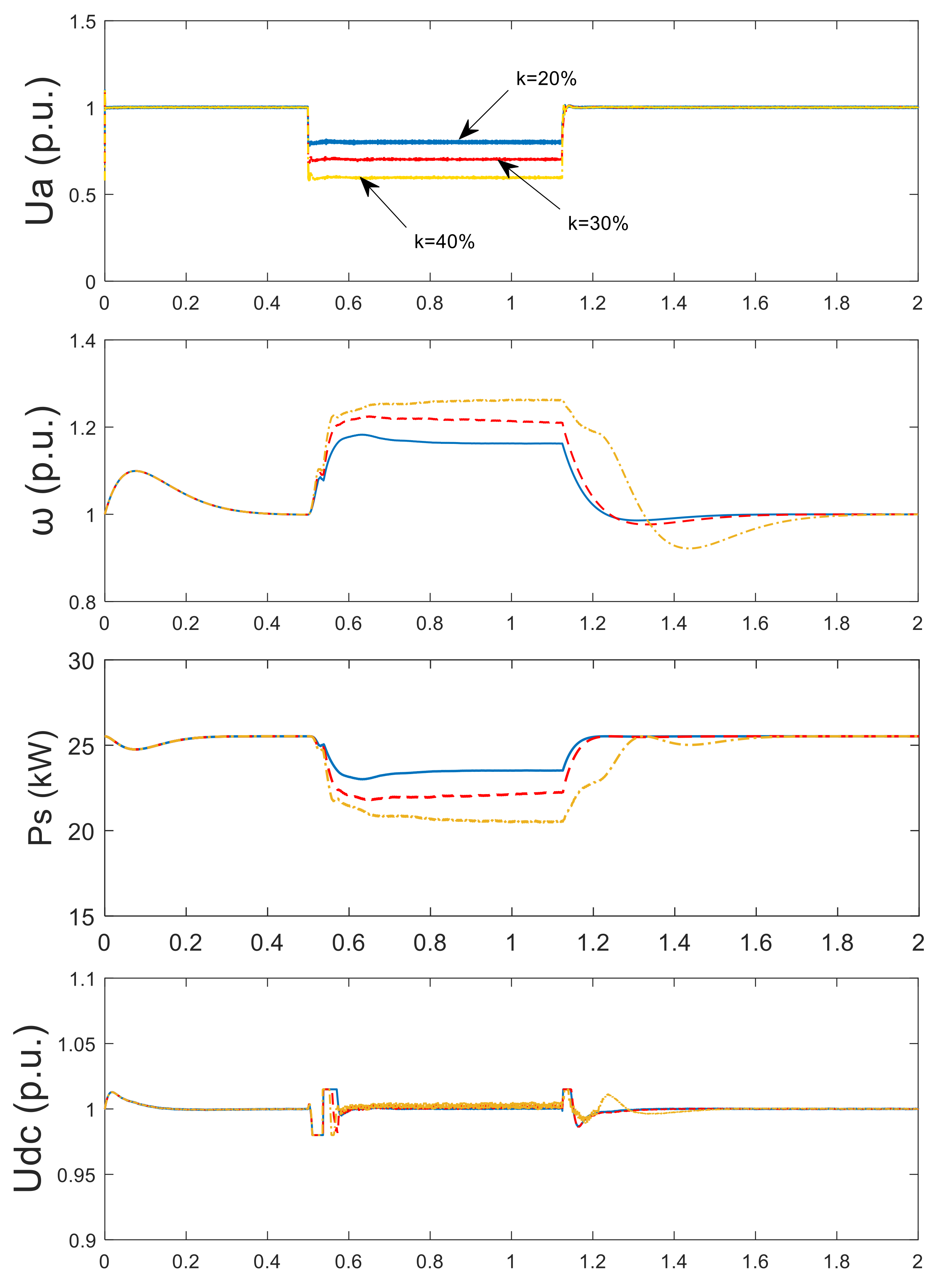
6.1.1. The Simulation Results of the Rotor Overspeed Control Scheme
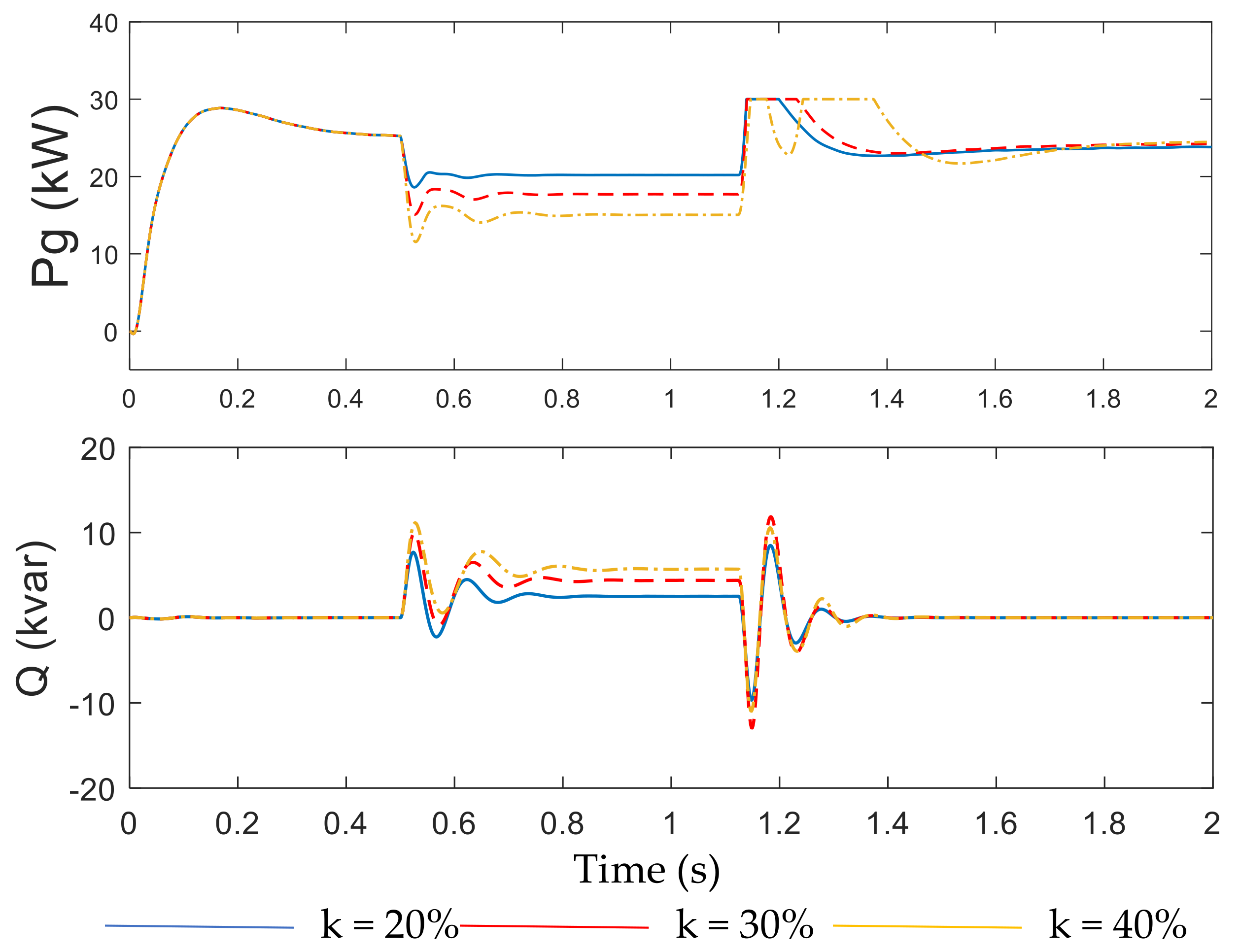
The response characteristics of PMSG-connected system with the rotor overspeed control scheme under faults are shown in
Figure 11. According to the voltage sag depth, the rotor speed
ω is regulated to reduce the input power of MSC, so that it can maintain the power balance of the system and keep the DC voltage fluctuated in the range within permission. The GSC can provide the reactive power to the grid under the voltage sags. When the voltage sag depth
k > 30%, the rotor speed has exceeded the upper limit of wind turbine, which is not allowable in practice.
6.1.2. The Simulation Results of the SCES Control Scheme
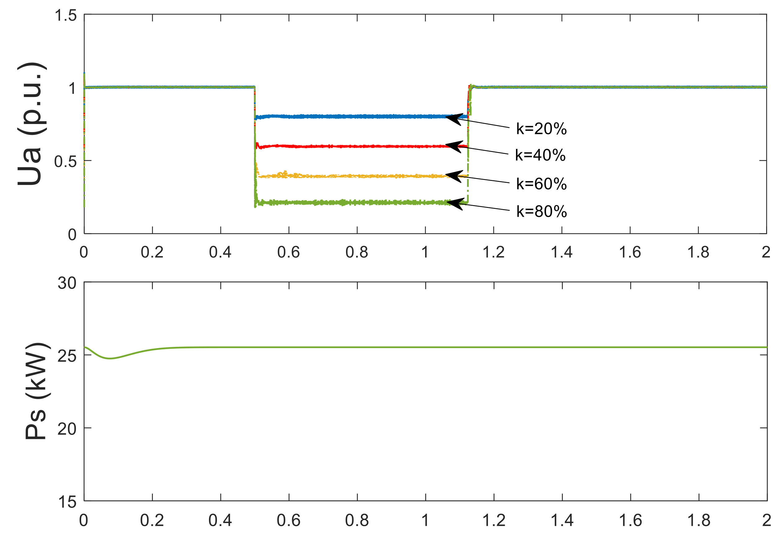
The response characteristics of PMSG-connected system with the SCES control scheme under faults are presented in
Figure 12. The input power of the MSC remained unaltered under any voltage sags because there no measures were adopted in the machine side. The unbalance power of the DC-side leads to the fluctuation of DC voltage. The SCES was utilized to absorb the unbalanced power on the DC side and stabilized the DC voltage. The GSC was used to provide the reactive power to enhance the LVRT capacity. When the worst fault occurred (i.e., the voltage sag depth
k was 80%), the voltage of the SCES
Usc increased from 230 to 279 V, SOC increased from 76% to 93%, the two values of the SCES were both in the allowable limit. The SCES control scheme could enhance the LVRT capacity of the PMSG under the all levels of faults.
6.1.3. The Simulation Results of Coordinated Control Scheme I: Overspeed-Before-Storing
The rotor overspeed control and the SCES control are combined to enhance the LVRT capacity under all voltage sags and maintain that the rotor is not out-of-limit. When the voltage sag depth
k ≤ 30%, the rotor overspeed control is adopted; otherwise, the SCES control is adopted. Since the two control schemes are still used separately, the simulation results were the same as those in the
Section 6.1.1 and
Section 6.1.2.
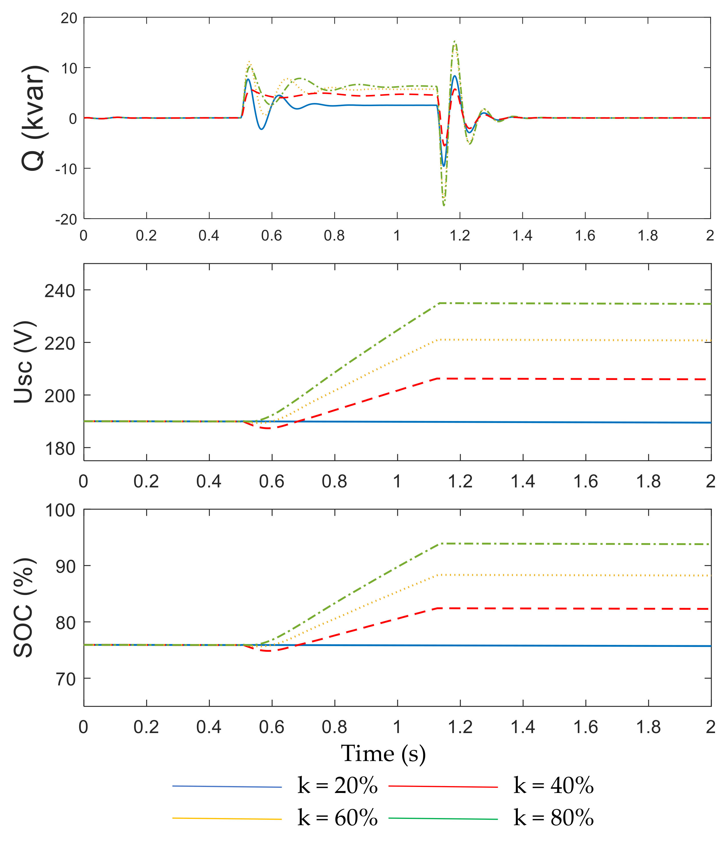
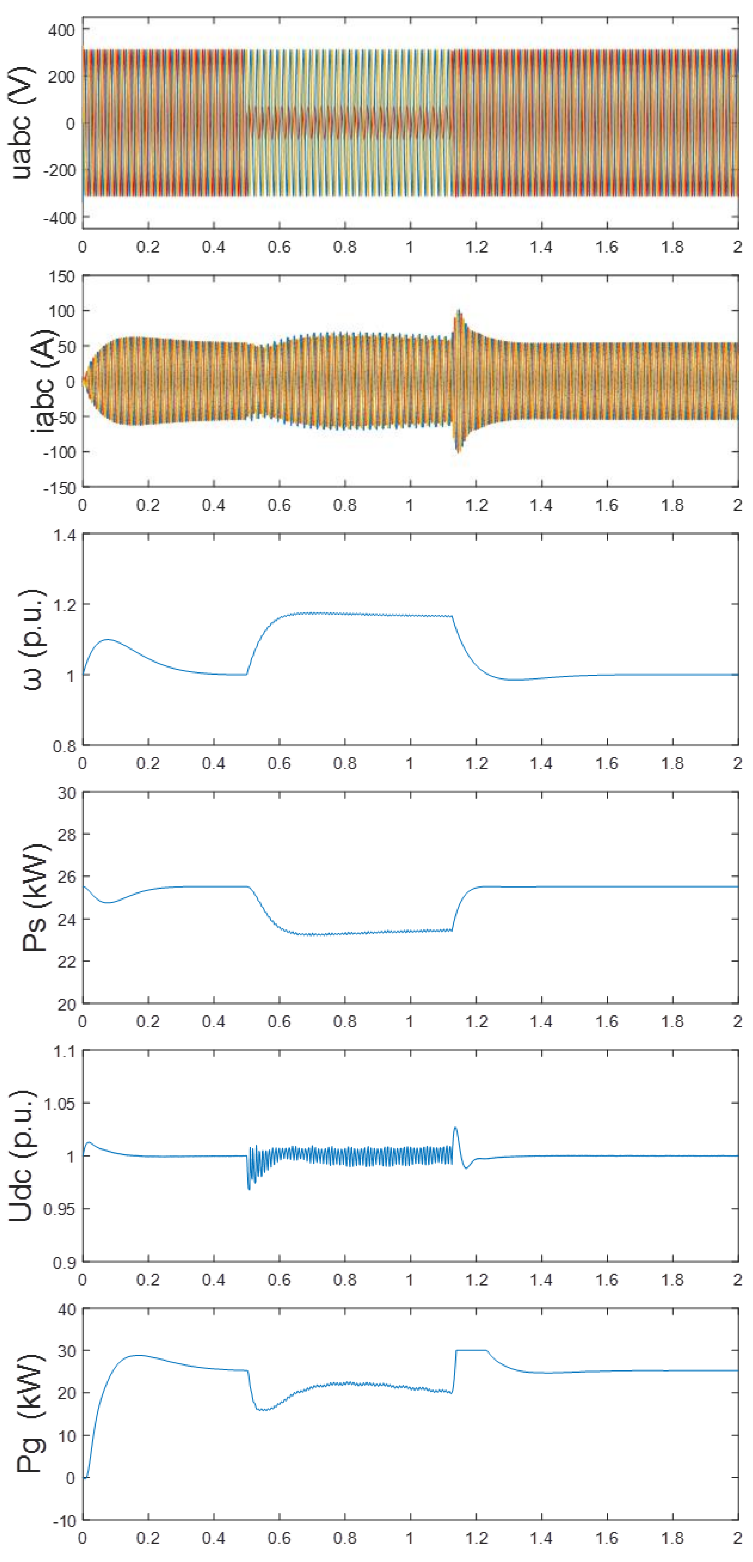
6.1.4. The Simulation Results of Coordinated Control Scheme II: Overspeed-While-Storing
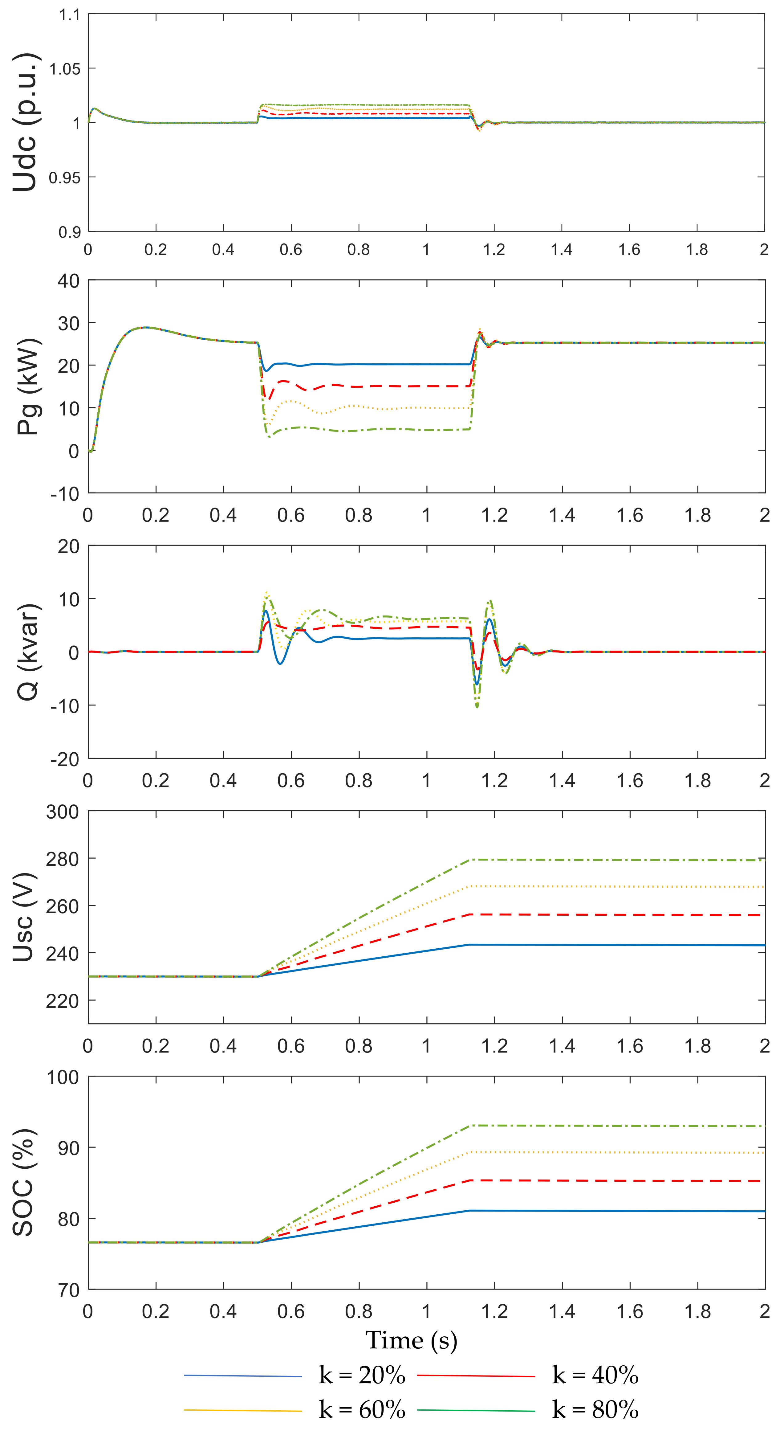
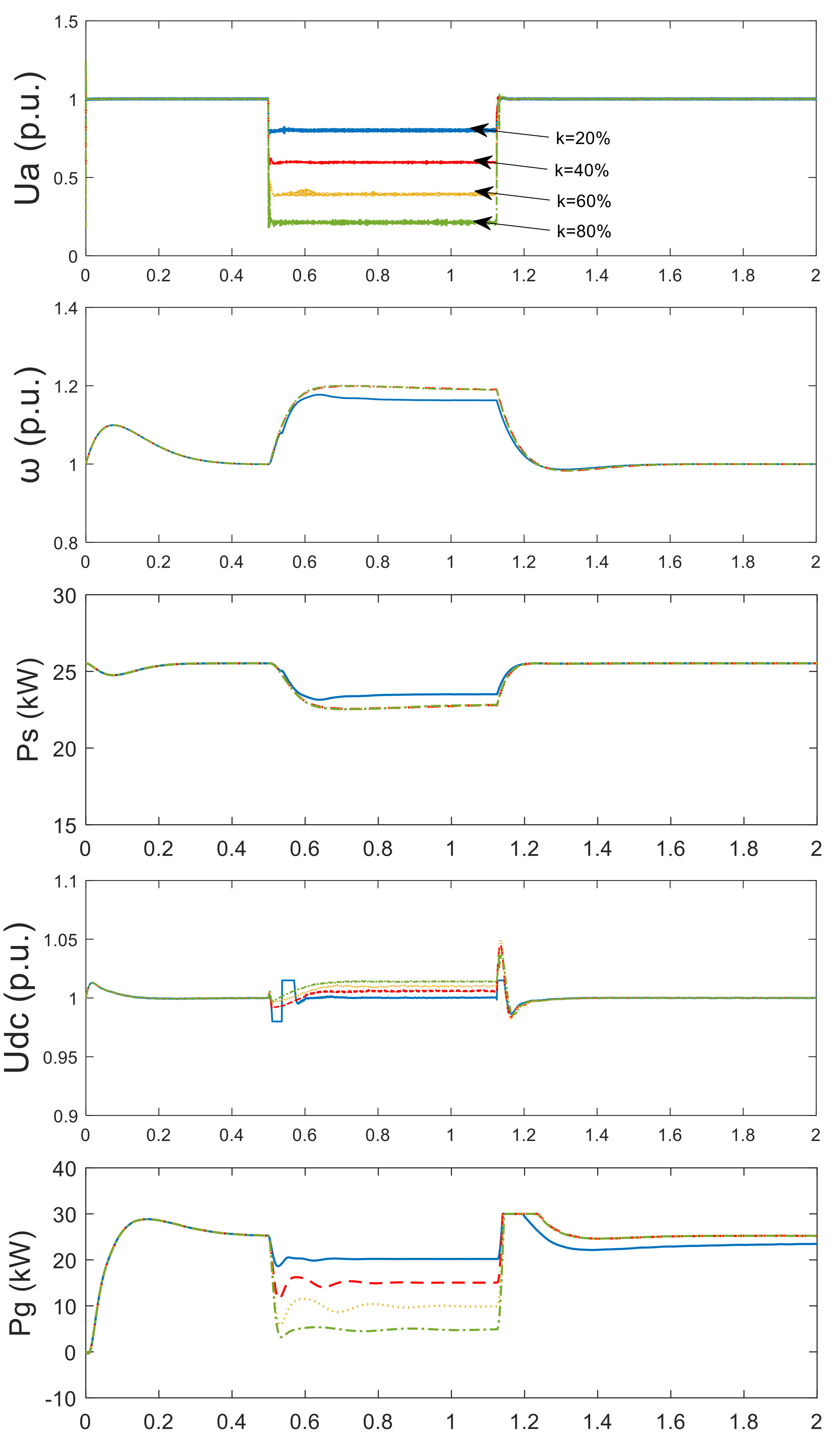
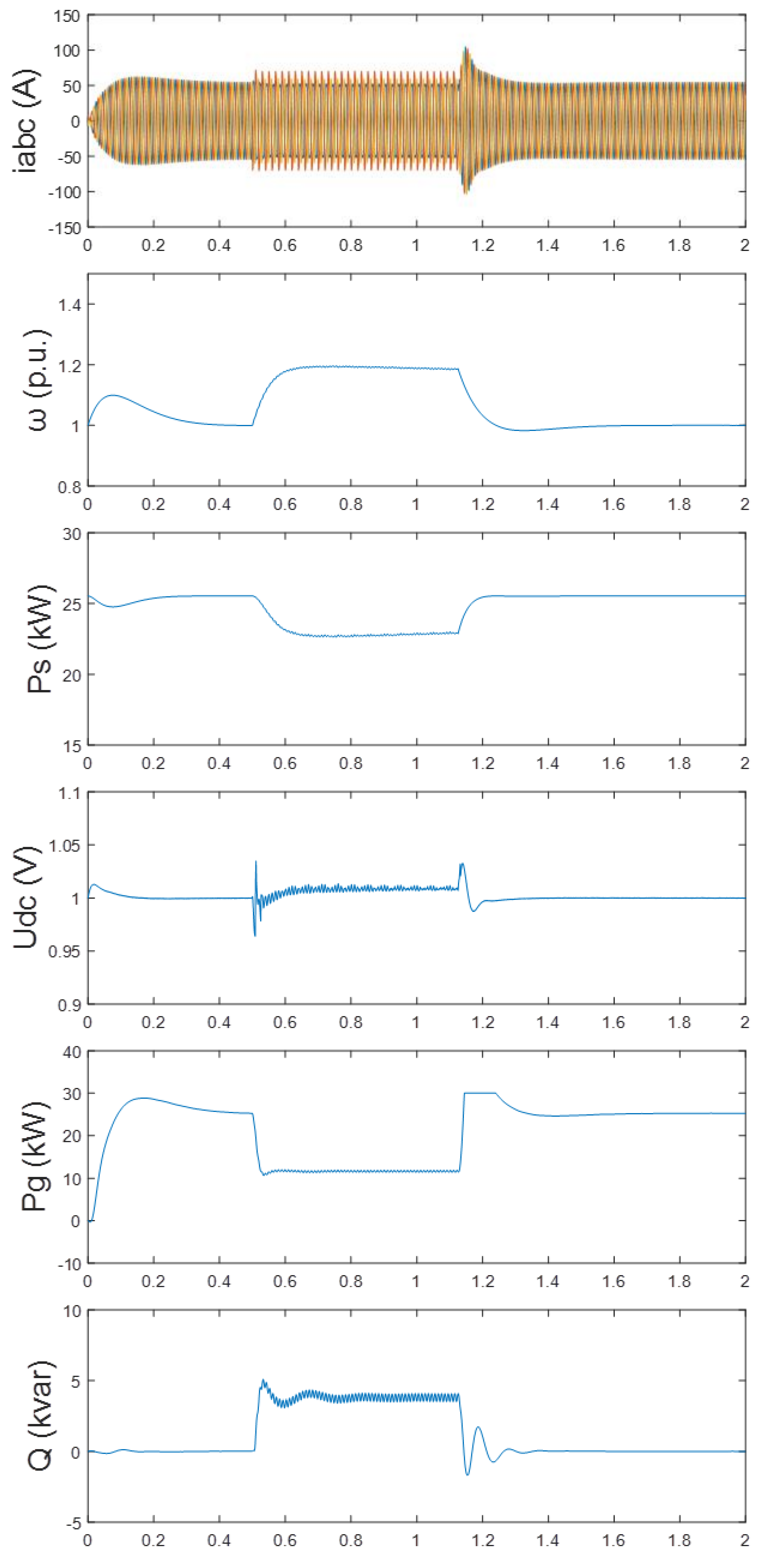
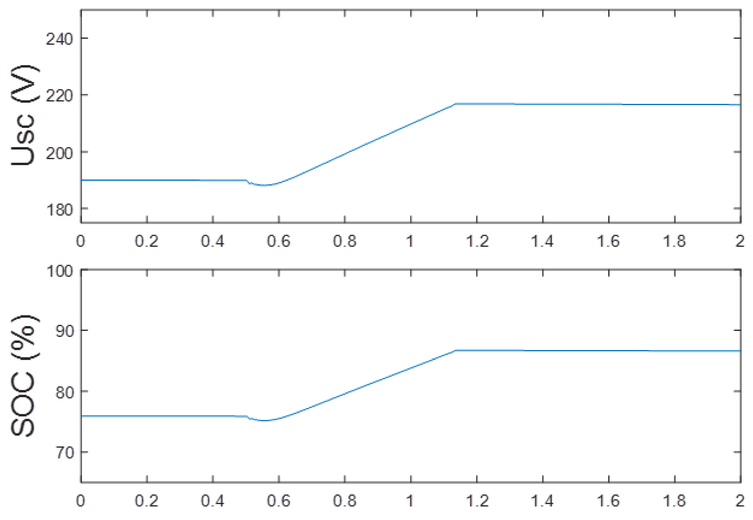
The response characteristics of PMSG-connected system with the coordinated control Scheme II under faults are described in
Figure 13. When the voltage sag depth
k ≤ 30%, the input power was declining by regulating the rotor speed, while, the SCES was inoperative. When the voltage sag depth
k > 30%, the rotor speed was set to the maximum 1.2 p.u. to reduce the input power. Meanwhile, the bidirectional DC–DC converter worked in the buck mode and the SCES absorbed the excess energy of the DC side. The GSC provided the reactive power to support the LVRT of PMSG. Comparing with the SCES control scheme, the capacity configuration of the SCES was decreased. The coordinated control Scheme II improved the stability and economy of the system simultaneously. As seen, even though the worst fault occurred (i.e., the voltage sag depth
k was 80%), the two values of the SCES were in the allowable limit.
6.2. The Simulations Results of Overspeed-while-Storing Control under Asymmetrical Faults
Actually, only 12% of grid dips are the symmetrical fault. Therefore, it is necessary to verify the performance of the overspeed-while-storing control proposed in this paper under asymmetrical faults. In this section, the overspeed-while-storing control under the two asymmetrical faults, which are single line-to-ground fault and double line-to-ground fault, were simulated and analyzed in detail.
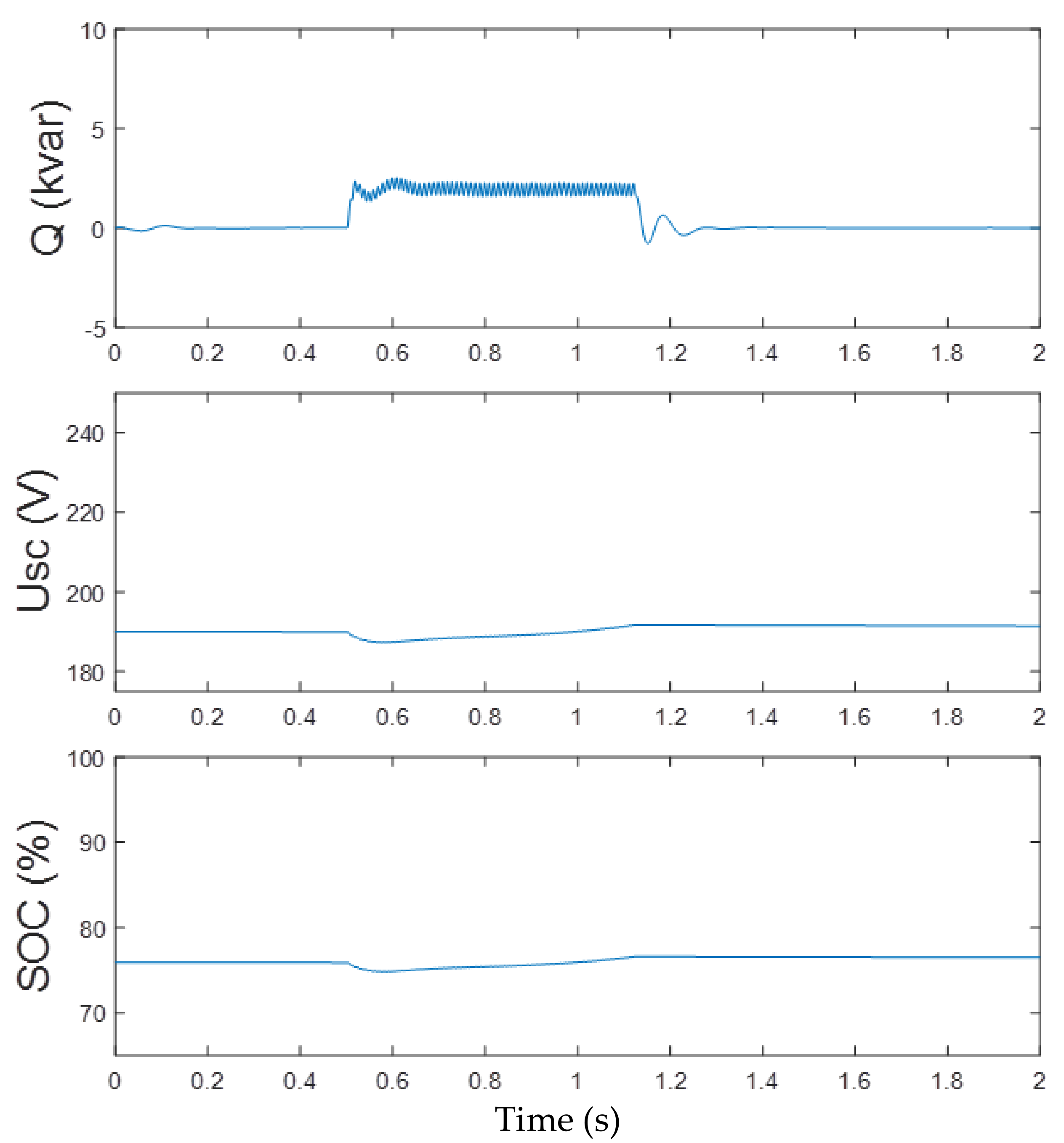
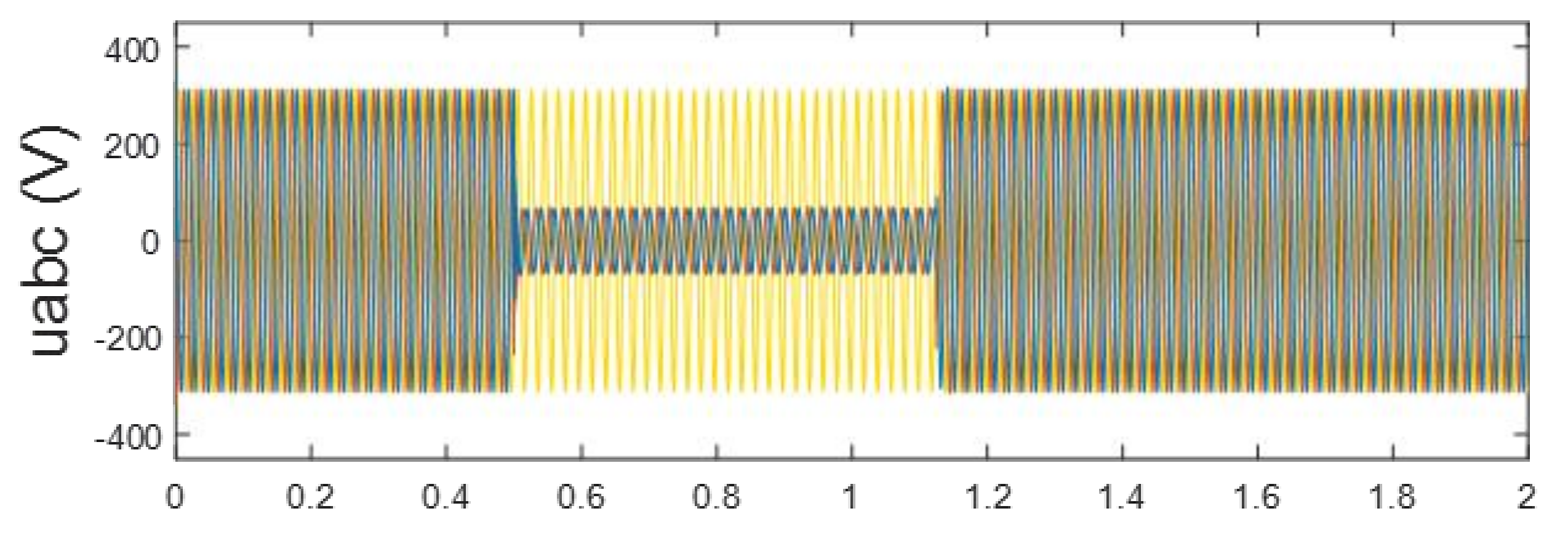
6.2.1. The Simulations Results under the Single Line-to-Ground Fault
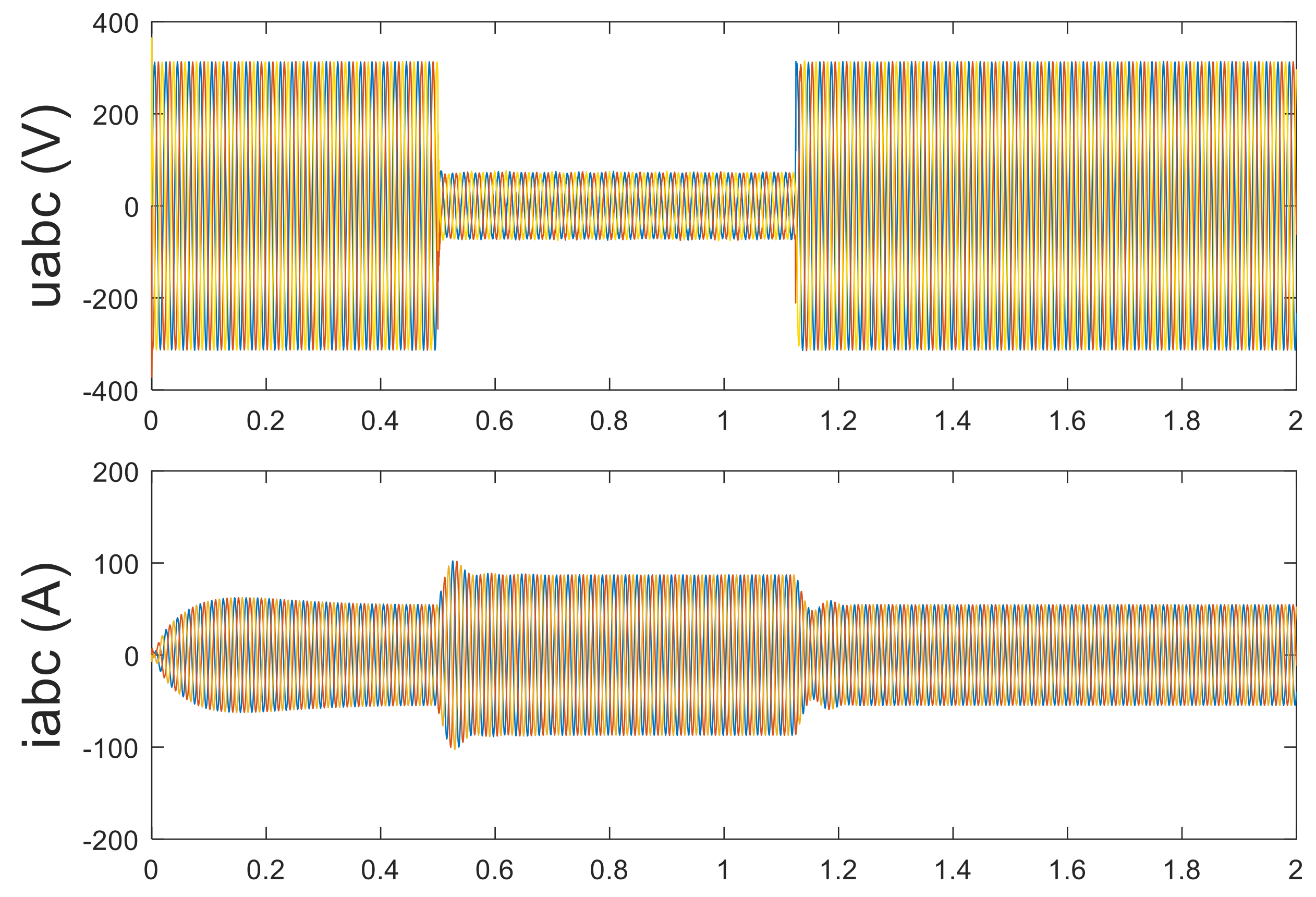
In
Figure 14, it can be observed that, when the voltage of A-phase sagged to 20% (i.e., the maximum degree of voltage sags), the rotor speed was increased but did not reach to the upper limit, that is the unbalanced power can be eliminated only by regulating the rotor speed, and then the SCES was inoperative. In addition, the reactive power generated by the GSC contained 2 ω oscillations due to the negative component of the grid, and the voltage of DC-side also consisted of 2 ω oscillations. However, the oscillation of DC voltage was within the allowable range. Apparently, the overspeed-while-storing control fulfilled the LVRT of PMSG and prevented the DC capacitor from overvoltage under single line-to-ground fault.
6.2.2. The Simulations Results of the Double Line-to-Ground Fault
Another simulation of the overspeed-while-storing under the double line-to-ground is shown in
Figure 15, when the voltage of B-phase and C-phase sagged to 20%, the rotor was increased to the maximum value (i.e., 1.2 p.u.) and the surplus power of DC-side was absorbed by the SCES. The values of SCES were in the allowable range due to the capacity being configured under the most severe fault (i.e., symmetrical fault). It can be seen that the DC voltage and reactive power suffered 2 ω oscillation during faults, as a result of the negative component of the unbalanced voltage. However, this 2 ω oscillation was small enough not to affect the stability of the system. Thus, the overspeed-while-storing control fulfilled the LVRT of PMSG and prevented the DC capacitor from overvoltage under the double line-to-ground fault.
6.3. The Comparison between the Conventional Control and the Overspeed-while-Storing Control under Faults
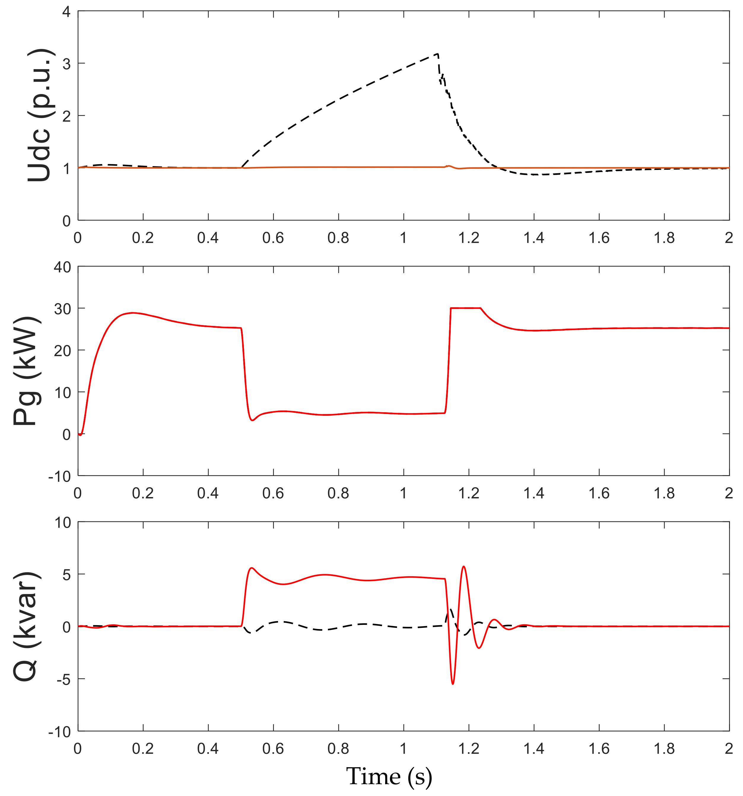
In conventional control [
24], the 1.5 times current-limiting strategy and unity power factor control were adopted in GSC. As shown in
Figure 16, when the voltage sagged to 20%, the voltage of DC-side could be reached to triple of rated value and there was no reactive power generated by the GSC in conventional control. Whereas, the DC voltage could be stabilized in the allowable limit and the GSC could provide reactive power under faults by using overspeed-while-storing control. According to the grid codes of the power system, the overspeed-while-storing control could fulfill the LVRT requirements effectively.
7. Conclusions
A novel LVRT control strategy for the PMSG-based wind turbine generator (WTG) based on the coordinated control named overspeed-while-storing is presented in this paper. Particularly, when the voltage sags were slight (i.e., the voltage sag depth k ≤ 30%), the mismatch issue between the input power and the output power could be solved by only regulating the rotor speed. Otherwise, the rotor speed was set to the maximum to reduce the input power to the maximum extent. Meanwhile, the supercapacitor energy storage (SCES) was utilized to absorb the excess energy of the DC side to maintain the DC voltage stability. The coordinated control method proposed in this paper, on the one hand, could fulfill the LVRT requirements of PMSG under all conditions of voltage sags; on the other hand, it requires the smaller capacity configuration than that in the SCES control scheme. Consequently, the proposed coordinated control method could improve the stability and economy of the system simultaneously. All these analytical results were validated in the single PMSG-connected system.
In this paper, only the LVRT under symmetrical faults and asymmetrical faults were discussed. Future works will focus on the condition of HVRT and the frequency regulation of the PMSG.


