1. Introduction
Hybridization of power generation is a strategy that several different energy sources are collectively used to realize energy stability, electricity flexibility, and energy efficiency improvement. Many hybridization studies have focused on combining solar energy with fossil fuels [
1,
2], in which the concentrated solar energy is used as the heat source to raise temperature of working fluid prior to fuel combustion and improve energy generation efficiency [
3,
4]. With increasing attention on utilization of more renewable resources for power generation, combining concentrated solar energy with biogas becomes a potential alternative to solar–fossil-fuel hybrid power generation [
5,
6]. However, current research and development on solar–bio-hybridization have mainly focused on large power generation ranging from a few hundred kW to several MW [
6,
7,
8,
9]. Only a few studies reported solar–bio-hybrid micro-power (less than 100 kw) generation [
10,
11]. Considering end-users of such power generation technologies, there is a high demand on small-scale distributed renewable systems for farm/food operations and remote villages/towns. Therefore, in-depth studies on small-scale solar–bio-hybrid power generation are very much needed to extend the hybridization concept to a wider range of applications.
Anaerobic digestion (AD) is an existing biological conversion process that has been proven effective on converting wet organic wastes into biogas (containing methane and carbon dioxide). It is capable of producing clean electricity while also alleviating many of the environmental concerns associated with the wastes (odor, greenhouse gas emission, and ground water contamination) [
12]. In addition, different from large power plant operations, AD can be set up in small or medium scale for biogas generation such as wastewater treatment plants, food processing plants, and animal farms (i.e., more than 80% of the U.S. animal farms have less than 500 animals per farm) [
13]. Combining AD operation and solar thermal collection to develop small-scale solar–biogas-hybrid power generation could provide a win–win solution to treat organic wastes and satisfy the energy demand of residential and farm operations.
Solar thermal technologies are classified as low-, medium-, and high-temperature solar thermal collection [
14]. Due to the temperature requirement of turbines for power generation, medium- and high-temperature solar thermal collections are suitable for the hybridization system. Medium-temperature (approximately 400 °C) solar thermal technologies often use a parabolic trough to collect solar energy. The central tower receiver and parabolic dish are the high-temperature (more than 500 °C) solar thermal technologies. Considering the size of power plants, central tower receiver is mainly used by solar thermal power plants to generate electricity in the magnitude of 100 MW or above. It requires large solar fields, and the operating temperature typically ranges from 600 °C to 1400 °C [
14]. Meanwhile, the parabolic dish and parabolic trough are the solar thermal technologies that could be used for small- and medium-scale power operations and generate electricity in the magnitude of kW.
In order to investigate and develop small-scale solar–bio-hybrid power generation, 30 kW power generation systems including three-unit operations of AD, a solar thermal collector, and an engine are comprehensively analyzed in this study. Biogas from AD and thermal energy from solar collection are used as the energy sources to generate electricity and heat. Gas and steam turbines as engine units are compared to conclude the preferred one for the small-scale solar–bio-hybrid system at different locations. Net capacity factor (the ratio of the energy output to the total energy generation of the system in a given time duration) and solar and biogas utilization factors (percentage of each energy source used to generate the electrical energy) are used as parameters to evaluate energy generation and optimize system configuration.
2. The Studied Small Solar–Bio-Hybrid Power Generation Systems
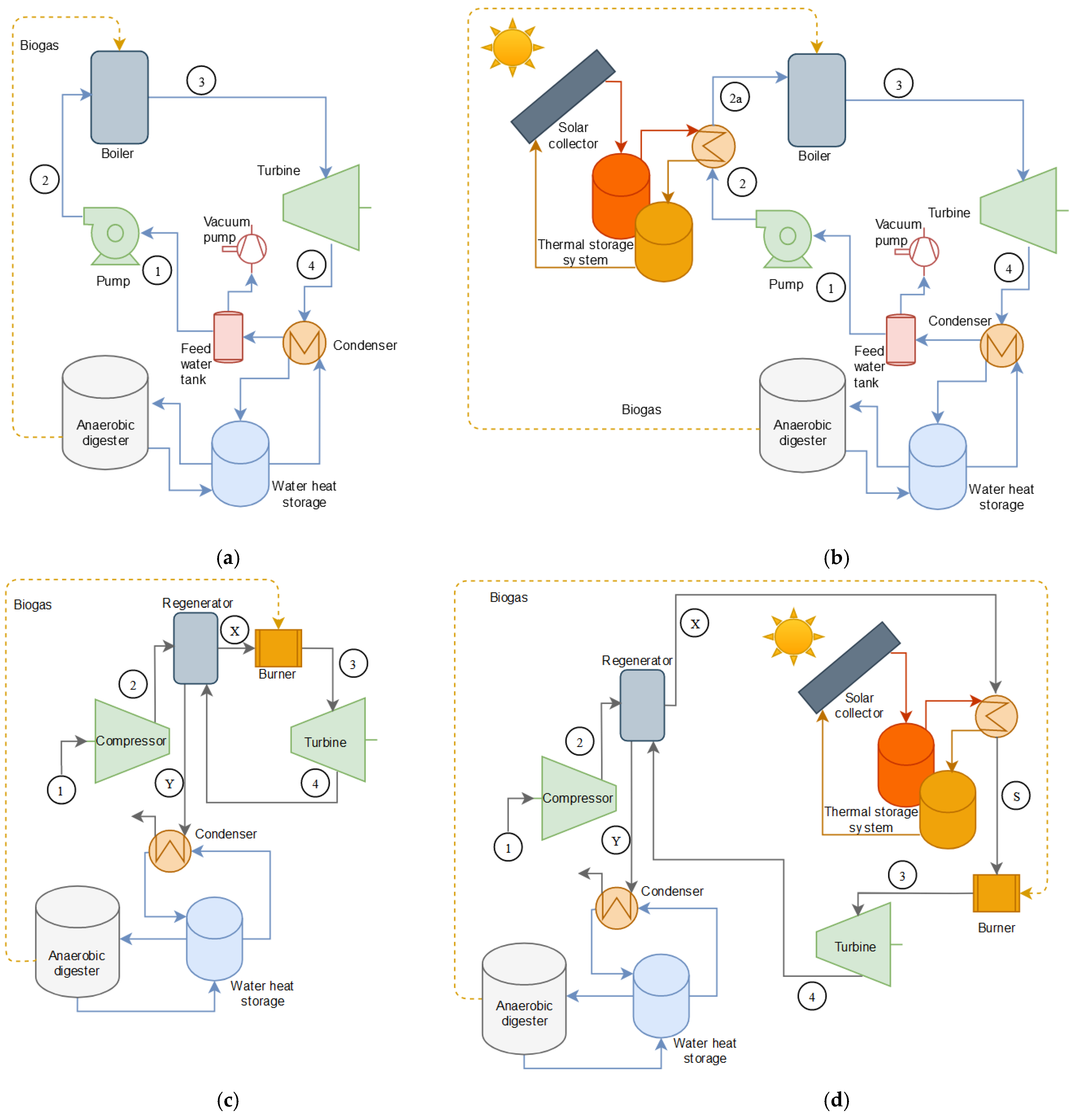
Thermodynamic models were established to analyze solar–bio-hybrid systems with gas and steam turbines, respectively (
Figure 1). Biogas production for the studied systems was based on a biogas plant using thermophilic AD on the mixture feed of dairy manure and food wastes (90:10 ratio, 5% total solids) [
15]. The AD with a culture temperature of 45 °C and a hydraulic retention time (HRT) of 20 days produced 0.64 m
3 biogas per m
3 digestion solution per day with 0.38 m
3 methane (the lower heating value (LHV) of biogas is 23 MJ/m
3 [
16]) and 0.26 m
3 carbon dioxide. The steam turbine includes a condenser in a close-loop circuit (
Figure 1a). The gas turbine uses a regenerator to transfer energy from exhaust gases into compressed air in an open-loop air circuit (
Figure 1c). Both systems contain a water heat storage to collect energy from the thermodynamic cycle to satisfy the heat demand of the anaerobic digester (maintaining digestion temperature and heating the influent). Configurations of solar–bio-hybrid power generation systems (which include a secondary heat source of solar energy) are slightly more complicated than turbine power generation systems, in which molten salt is used as the short-term solar thermal storage [
17]. In the solar–bio-hybrid system with a steam turbine, a heat exchanger is implemented to use heat from the solar thermal storage to heat the working fluid prior to the boiler. The boiler further heats the working fluid to generate superheated steam for the steam turbine (
Figure 1b). The solar–bio-hybrid system with a gas turbine uses heat from the solar thermal storage to raise temperature of the hot air from the regenerator in the heat exchanger before being mixed with biogas in the burner to generate heat (
Figure 1d). The analyses are based on a constant electricity generation of 30 kW for all the studied systems. Operational parameters of the thermodynamic models are listed in
Table 1.
Rankine cycle was used to simulate performance of the biogas steam turbine (
Figure 2a). The working fluid of water is pumped into the boiler that is maintained at constant pressure (
Figure 1a,b). Power consumption of the pump and the enthalpy at point 2 in
Figure 1a and b are calculated by:
where
is the pump work (kJ/kg
water),
is the pump efficiency (38.8% from a Grundfos pump Model CR 1-19, considering electrical, mechanical and hydraulic losses),
is the specific volume (m
3/kg),
and
are the inlet and outlet pressure in the turbine,
is the enthalpy at given temperature and pressure conditions (kJ/ kg
water). To satisfy the required temperature and pressure of feed water for the selected 30 kW steam engine, the heat input (
) is calculated as follows:
where
is the fuel-to-steam boiler efficiency (0.80) [
23]. Cleaver Brooks model CB 40 with a dryback integral burner was selected considering both radiation and convection losses. It has 15% excess air in the exhaust flue gas at 100% firing rate.
Fuel-to-electricity efficiency of the system is calculated based on fluid properties in inlets and outlets of the turbine and pump:
The heat extracted (
) for digester heating is calculated by:
where
is the condenser effectiveness (set at 0.85), and
is the heat of condensation of water.
The simulation results for the steam turbine are presented in
Table 2. Enthalpies at points 1, 2, and 3 (
Figure 1a and
Figure 2a) are 191.81, 194.91, and 2816.1 kJ/kg, respectively. Temperatures at points 2 and 4 are 46.31 °C and 45.81 °C. The corresponding heat input and heat extraction are 534.06 and 331.56 kW, respectively. Efficiencies for this particular equipment under the working parameters show that 5.62% of the biogas energy is transformed into electricity, and 62.08% of the biogas energy is turned into useful heat.
In the solar–bio-hybrid steam power system (
Figure 1b), solar thermal energy reduces the amount of heat required by the boiler, and consequently decreases the biogas consumption. If there is enough solar radiation, the solar thermal energy heats the water up to
. If there is not enough solar radiation, the boiler provides partial energy to adjust the steam quality for turbine operation
.As for the gas turbine, Brayton cycle (
Figure 2b) was used to simulate the turbine performance [
24]. The temperature (
) after the compressor (point 2 in
Figure 1c,d and
Figure 2b) was calculated by:
where
is the pressure ratio between inlet and outlet in the compressor,
is the ratio of the specific heat at constant pressure and the specific heat at constant volume,
is the compressor isentropic efficiency (
[
19,
22]). The temperature after the regenerator (Point x in
Figure 1c,d) is given by:
where
is the regenerator effectiveness (
[
20]). The heat input (
QFg) to the burner is calculated by:
where
. is the air mass flow,
is the average specific heat between
and
(kJ/kg·K), and
is the burner efficiency (
, obtained from a fuel requirement of 415 × 10
3 kJ/hr of LHV based on [
21]). The temperature of the exhaust gases after the regenerator (Point Y in
Figure 1c,d) is given by:
The fuel-to-electricity efficiency for the gas micro turbine system is:
The extracted heat (
QHg) from the exhaust gases for digester heating is calculated by:
where
is the average specific heat between
and
(kJ/kg·K),
is the temperature of the exhaust gases (assumed as 60 °C) and
is the effectiveness of the heat exchanger and set at 0.75.
Simulation results for the gas turbine analysis are listed in
Table 3. At a constant air inlet temperature, input and extracted heat are 111.31 kW and 32.01 kW, respectively. The compression increases air temperature from 288 K at point 1 to 424.78 K at point 2. The regenerator further increases air temperature to 821.88 K at point X before mixing with biogas in the burner. The gas turbine unit uses 26.95% of biogas for electricity generation, and 28.76% of biogas to generate heat.
With the addition of solar thermal energy (
(kW)) (
Figure 1d), heat demand for the biogas burner is also reduced. The temperature after the solar collector is calculated as follows:
Where is the average specific heat between . and (kJ/kg·K).
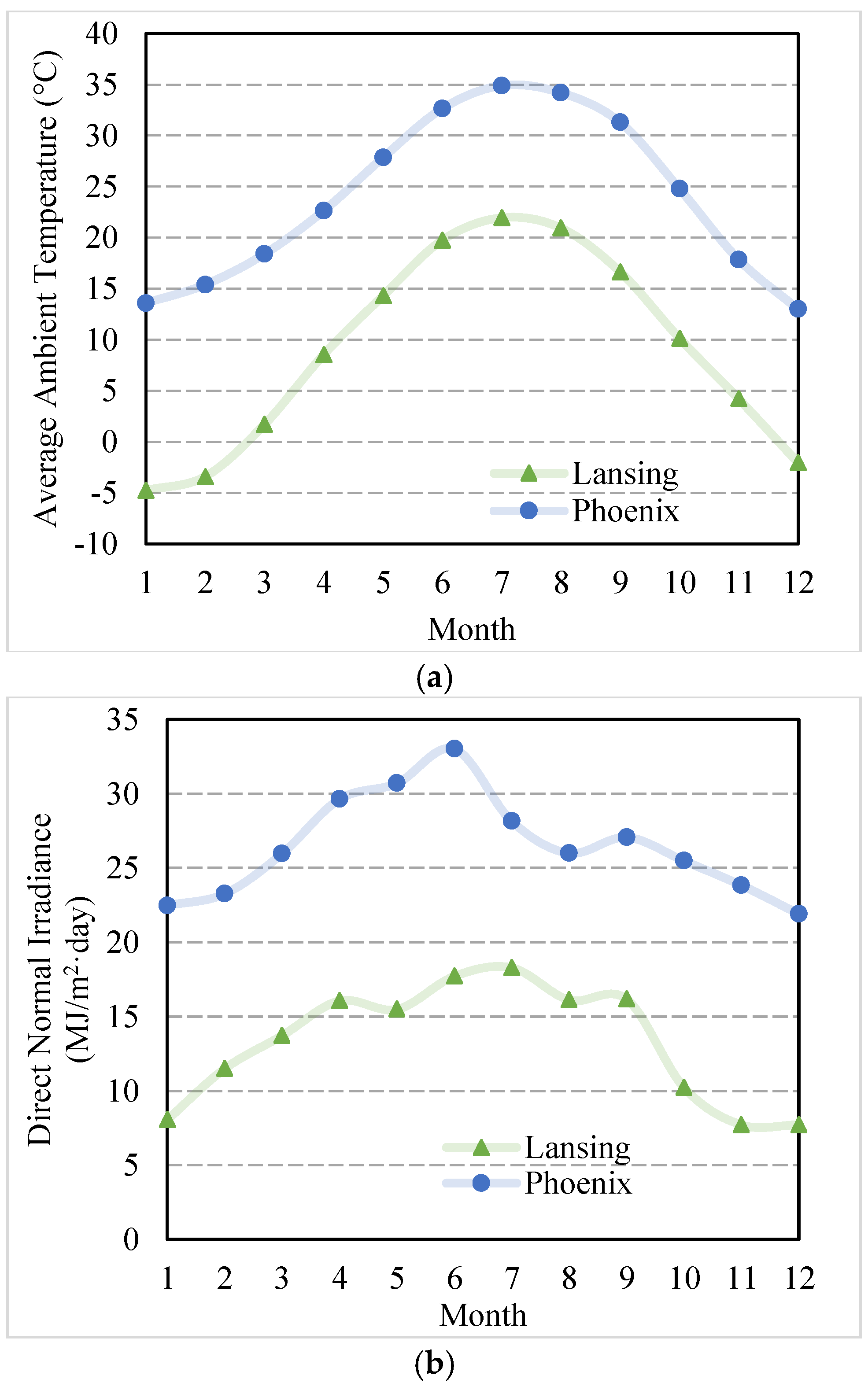
In addition, due to seasonal and geographical variation of solar radiation, location of the studied systems has a great impact on their performance. Direct normal irradiance (DNI) and ambient temperature are decreased following the increase in latitude. Therefore, two locations of Lansing (MI) and Phoenix (AZ) in the United States with significant different temperatures and solar radiations were selected to study the impact.
Figure 3 represents solar radiation and ambient temperature in a year for both locations [
25,
26].
2.1. Relationship between Solar Energy, Net Capacity Factor, and Ratio of Solar Energy to Biogas Energy
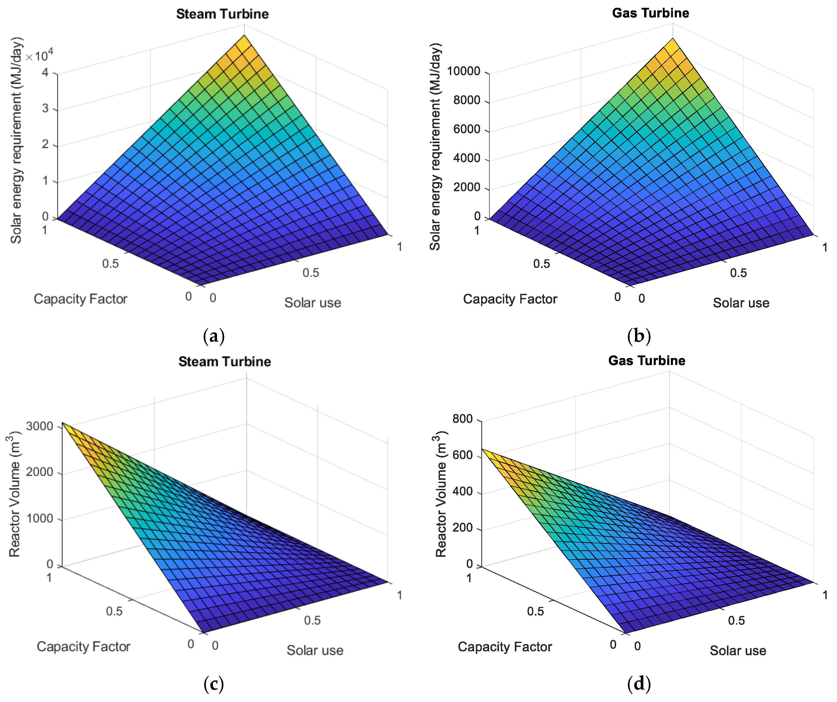
Biogas consumption for solar–bio-hybrid power systems (steam and gas turbines) depends on the usage of solar energy (the heat input from solar energy) and the net capacity factor of power generation. Effects of capacity factor and solar usage on digester volume and solar energy requirement for solar–bio-hybrid steam and gas turbine systems are presented in
Figure 4. With the increase in net capacity factor and solar usage, solar energy demands for both systems linearly increased. Meanwhile, the hybrid steam engine system demands more solar energy than the hybrid gas turbine system (
Figure 4a,b). For instances of full utilization of solar energy (100% solar usage and 1 net capacity factor) to power the hybrid systems, the hybrid steam turbine system requires 36914 MJ/day solar energy which is much higher than the demand from the hybrid gas turbine system (8978 MJ/day). Meanwhile, the required digester volume to generate biogas for 30 kW electricity generation increased with increase in net capacity factor and decrease in solar usage for both systems, and the hybrid steam engine system needs more digester volume than the hybrid gas engine system (
Figure 4c,d). At the point of 0% solar usage and 1 net capacity factor, the hybrid steam engine system needs 3134 m
3 of digester volume, while the hybrid gas turbine just needs 651 m
3 of digester volume.
2.2. Energy Requirement for Biogas Production
Thermal Energy Requirement of Biogas Production
Thermal energy is needed by anaerobic digestion to heat the feed and maintain the culture temperature at 45 °C. The energy requirement per day
(MJ/day) [
27] to heat the influent is:
where
is the digester volume (m
3),
is the hydraulic retention time (days),
is the feed density (1220 kg/m
3),
is the feed specific heat (3606 J/kg·°C),
is the culture temperature (45 °C),
is the feed temperature and assumed to be the same with ambient temperature once the ambient temperature is above 4 °C (the feed temperature is set at 4 °C once the ambient temperature is below 4 °C). The energy requirement to maintain the culture temperature
(MJ/hour) [
28] is calculated as follow:
where
is the digester surface area (m
2) (the ratio for height:diameter is 2),
is the R-value for the insulation (2.1133 °C·m
2/W).
Solar utilization value is selected based on the balance between thermal energy required by the anaerobic digester and thermal energy generated in the power generation system at a given net capacity factor. The thermal energy generated in the power system
(MJ/day) is calculated as follows:
where
is the heat generated (
or
) (kW), and
is the net capacity factor. The energy requirement per day
(MJ/day) can be expressed as:
Substituting Equation (15) and Equation (16) into Equation (17), and considering that:
The energy requirement per day can be calculated:
where
is the biogas requirement (m
3/day),
is the biogas productivity (m
3biogas/m
3digester·day),
is the energy provided by biogas (MJ/day),
is the heat of combustion of biogas (23 MJ/m
3),
is the heat input (
or
) (kW), and
is the solar utilization factor. The solar utilization factor can be calculated by a thermal energy balance:
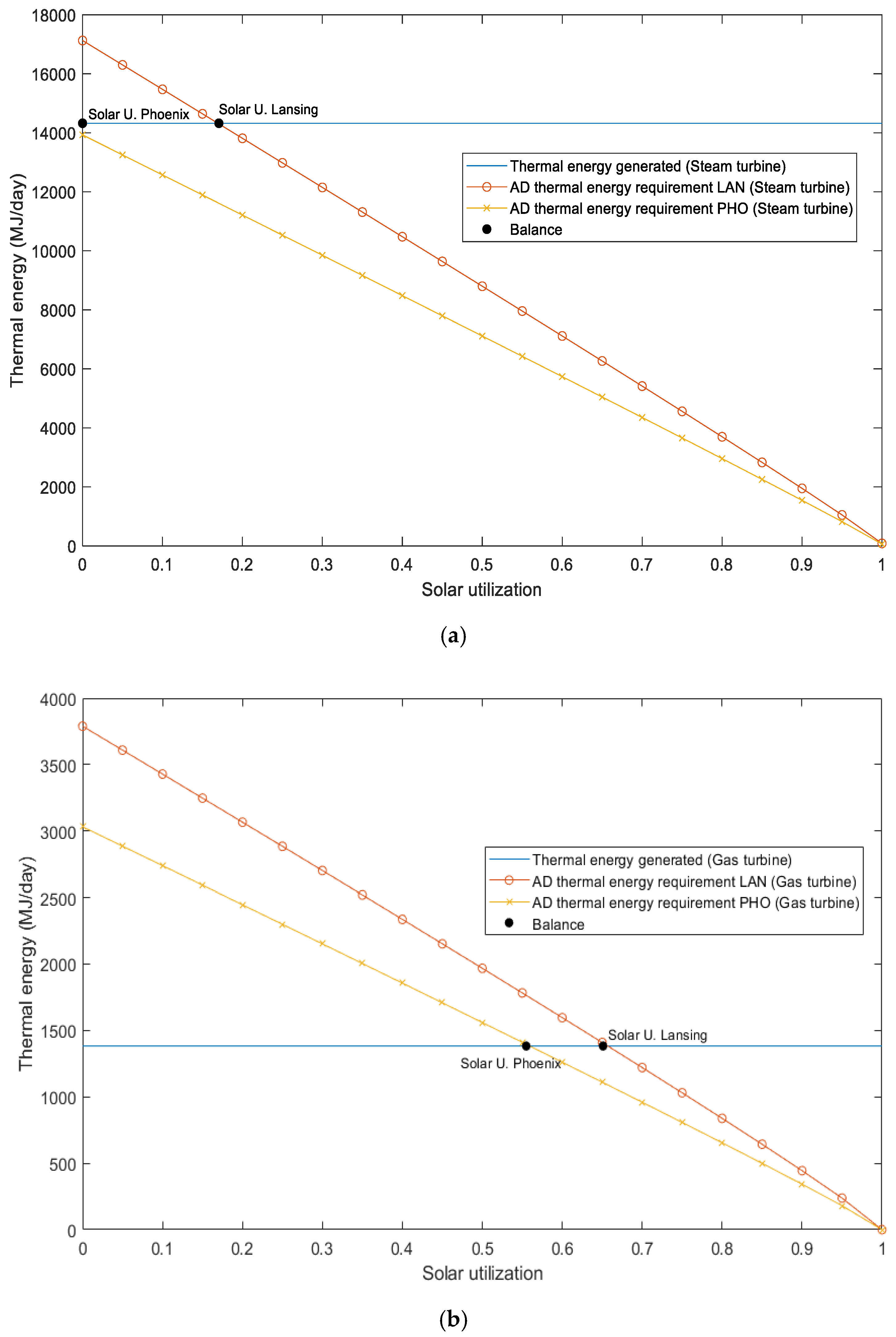
For instance of a given net capacity factor of 0.5, the relationship between solar utilization and required thermal energy by AD is shown in
Figure 5. To satisfy energy demands of heating the influent and maintaining the digestion temperature, 17.05% and 65.10% of solar utilization are required for the steam and gas turbines at Lansing, respectively, and the corresponding values at Phoenix are 0% and 55.49%. These values at the capacity factor of 0.5 are used as the base numbers to select anaerobic digester volume and solar collector for each location and power system (
Table 4).
2.3. Selection of Solar Thermal Collectors for the Hybrid Systems
Selection of solar thermal collectors for solar–bio-hybrid systems are based on the desirable temperature of the heat fluid for the steam and gas turbines. Central tower, parabolic dish, and parabolic trough are three most popular solar thermal collection technologies [
3,
4,
14]. Central tower solar collection can reach extreme high temperature (above 1000 °C), but requires a large footprint to accommodate solar reflectors, which is not suitable for small-scale solar power generation. While, the parabolic dish as a high temperature (500–900 °C) solar thermal collection and parabolic trough as a medium temperature (200–400 °C) collection are more suitable for small-scale solar power generation [
14]. Considering the required temperature of the heating fluid from steam (220 °C) and gas turbines (840 °C), the parabolic dish and parabolic trough are selected to be integrated with gas and steam turbines, respectively, for the small-scale solar–bio-hybrid power generation systems.
It has been reported that the optical efficiencies for parabolic trough and parabolic dish are approximately 0.76 and 0.93, respectively [
14,
29]. Solar concentration ratio (
) is another important parameter for solar thermal collectors and expressed as the absorber area (
) vs. collector area (
). Values of 70 and 750 are used as the concentration ratios for the corresponding parabolic trough and parabolic dish collectors [
14,
30].
Based on the collector type, working fluid temperature, and solar concentration ratio, the solar energy for the integration in the hybrid system can be calculated by the following equation:
where
is the solar heat collected (W),
is the direct normal irradiance at a given location (W/m
2 hourly based)
is the collector area (m
2),
is the heat loss due to optical losses (W),
is the heat loss in solar receiver (W), and
is the heat loss in fluid conduction through pipes (W). Models for solar collection system were obtained from references [
31,
32].
In addition, working fluids (water and air) have a large impact on the heat exchanger effectiveness. The overall heat transfer coefficient (the capability of heat exchanger to transfer thermal energy) of water is several orders of magnitude higher than that of air [
33,
34]; the thermal efficiency of air is correspondingly lower than water. Values of 0.70 and 0.85 are selected by this study as
for gas and water, respectively. Therefore, the heat that working fluid transfers from the absorber to the boiler and burner can be calculated as:
where
. is energy transferred (W) from absorber to working fluid and
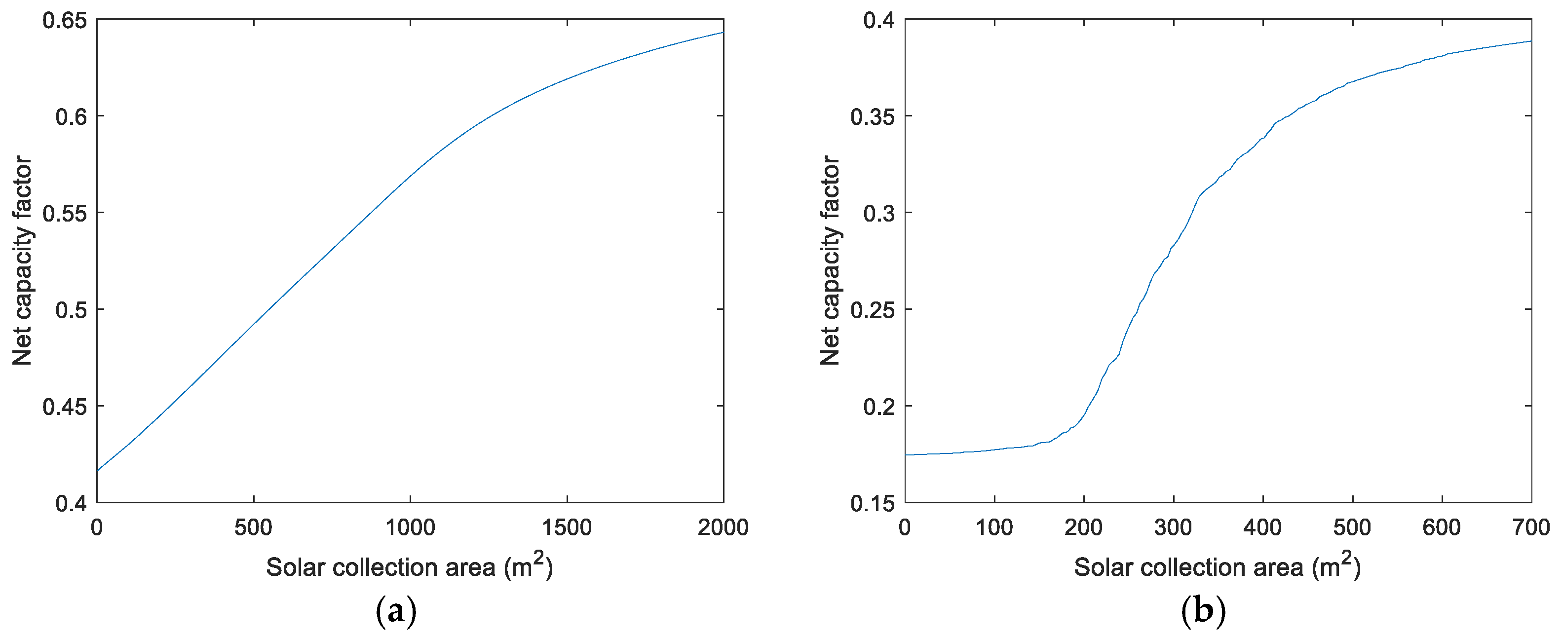
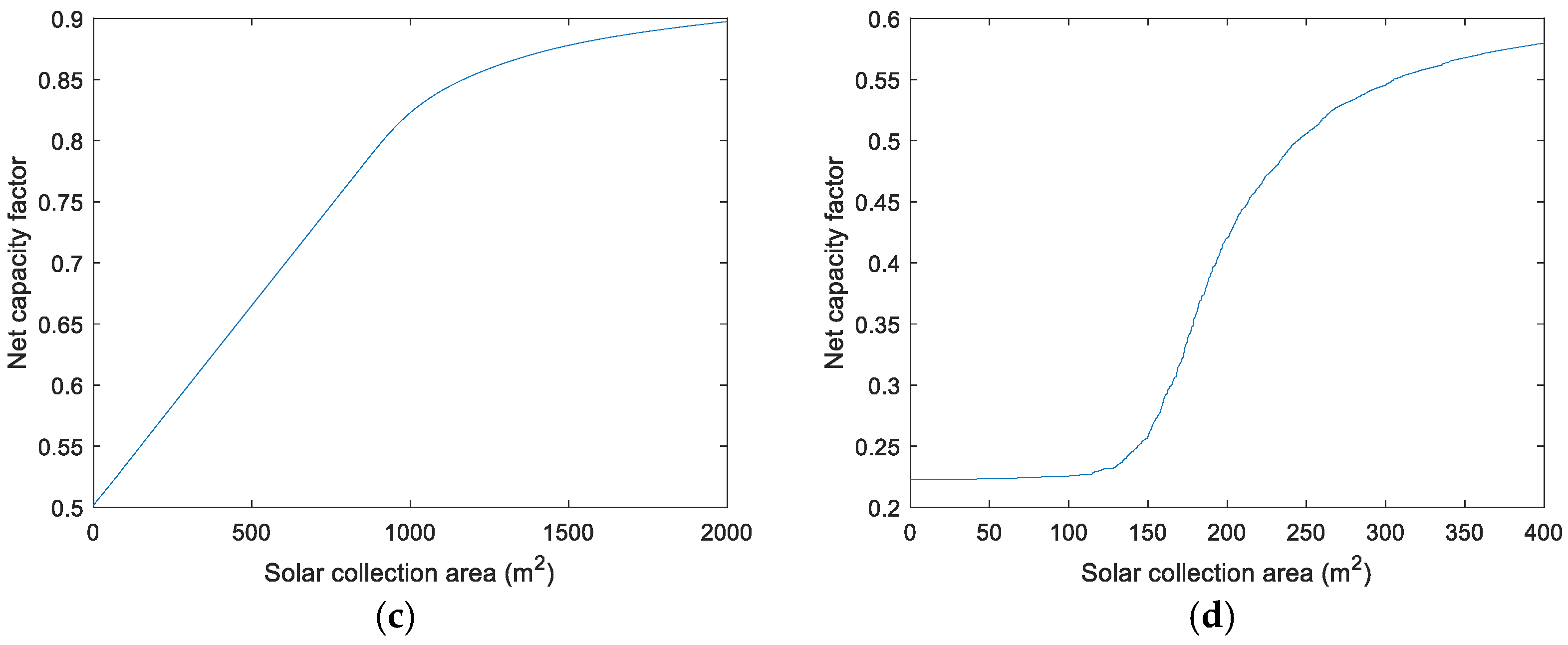
is the heat exchanger effectiveness. Solar collector areas required by the solar–bio-hybrid systems to generate 30 kW electricity under different net capacity factors are presented in
Figure 6.
For the selected net capacity factor of 0.5, the required solar collector area of the steam turbine at Lansing is 549 m
2. At Phoenix, the steam turbine system does not require solar collectors due to the positive balance between the heat generated from the digestion and the heat required to maintain reactor temperature (
Table 5). For the case of the gas turbine, the required solar collector area is 244.45 m
2 at Phoenix. However, the gas turbine system cannot achieve a net capacity factor of 0.5 at Lansing, even though the solar collector area is increased to 700 m
2 (
Figure 6b and
Table 5). This occurs due to the absence of long-term thermal energy storage for solar radiation as well as high thermal energy demand. Without long-term thermal storage, the collected energy is not able to satisfy continuous thermal energy demand of 111.31 kW for the gas turbine [
35].
3. Discussion
The system analysis shows the relationship between net capacity factor, digester volume, solar thermal utilization, and geographic location for both Brayton and Rankine cycles. According to system configurations (
Figure 1), the required highest temperatures in individual thermal cycles determine solar collector technologies that could be integrated into the solar–bio-hybrid power generation systems. In the case of the steam turbine (Rankine cycle), the maximum temperature (turbine inlet) is 200 °C (
Figure 1b), which could be achieved by medium-temperature solar thermal technologies such as the parabolic trough used by this study. However, the working fluid in gas turbine (Brayton cycle) needs to be heated by solar thermal energy from 548.73 °C at the outlet of the regenerator to 843.85 °C before the burner (
Figure 1d). High-temperature solar thermal technologies such as the parabolic dish selected by this study (the surface area of a parabolic dish ranging from 43 to 117 m
2) have to be used to satisfy the need of such temperature increase [
36,
37]. It is a limiting factor to further increase solar thermal energy utilization in the gas turbine hybrid system. Even though it is theoretically achievable to raise the temperature at the absorber of parabolic dish to above 1000 °C by extending the area of reflection, fabricating such large parabolic dishes may pose some manufacture and installation difficulties as well as economic barriers for small-scale applications.
Since solar radiation and ambient temperature significantly vary between seasons and locations, digester volume must be large enough in order to produce more biogas to satisfy the system energy demand once solar thermal energy is not able to fulfill the heating requirement (i.e., in the winter months at Lansing). This is the reason that the minimum solar utilization value for the system design is selected by this study based on maintaining the average net capacity factor of 0.5 in a year. Moreover, due to thermodynamic difference in fuel efficiency between gas and steam turbines, required digester volumes are different for the hybrid systems. The fuel efficiency of the gas turbine (26.95%) is much higher than that of the steam turbine (5.62%). The corresponding digester in the steam turbine hybrid system is approximately 10 times bigger than the one in the gas turbine hybrid system (
Table 4). The simulation results also demonstrate that the solar–bio-hybrid steam turbine system requires less solar collector area (549 m
2 and 0 m
2 for Lansing and Phoenix, respectively) than the gas turbine system (700 m
2 and 244.45 m
2 for Lansing and Phoenix, respectively) (
Table 5). It is mainly caused by higher values of the solar utilization factor for the gas turbine systems. The global efficiency (electricity and heat outputs vs. biogas and solar energy inputs) of the solar–bio-hybrid steam turbine system (67.7%) is higher than the solar–bio-hybrid gas turbine system (55.7%).
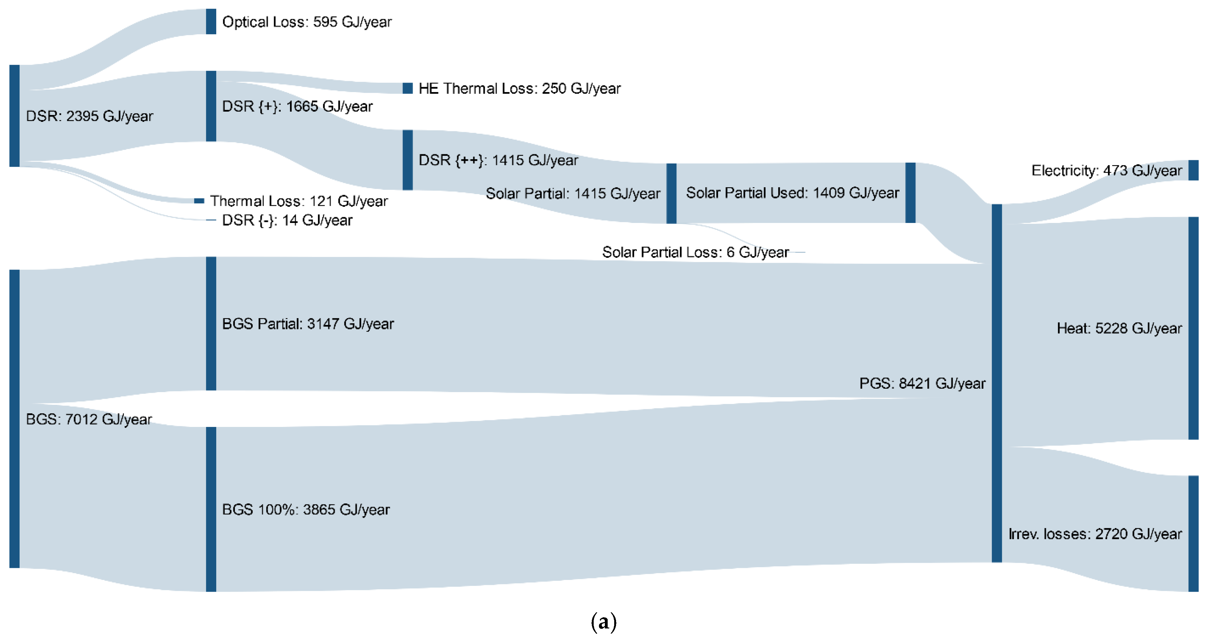
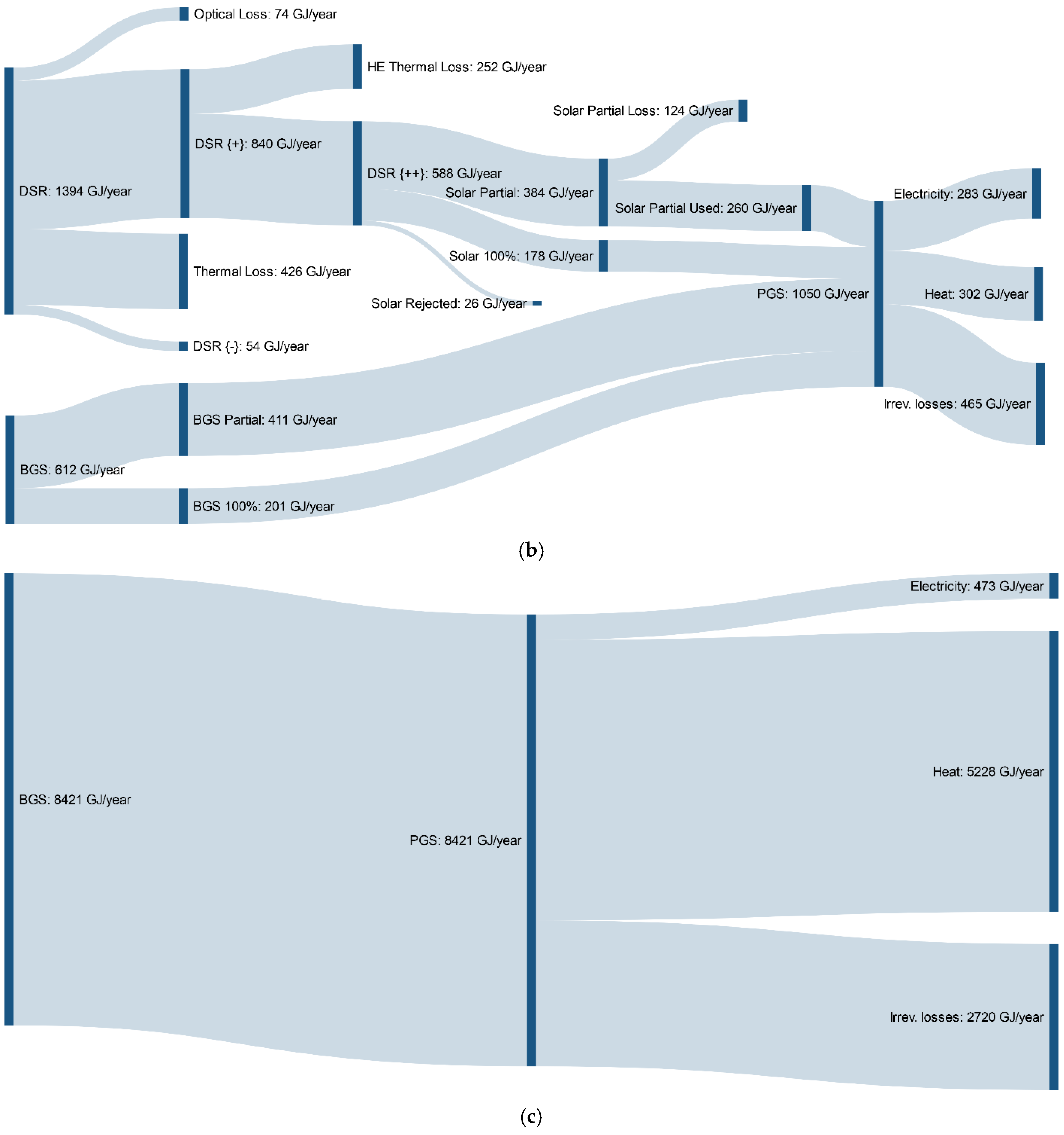
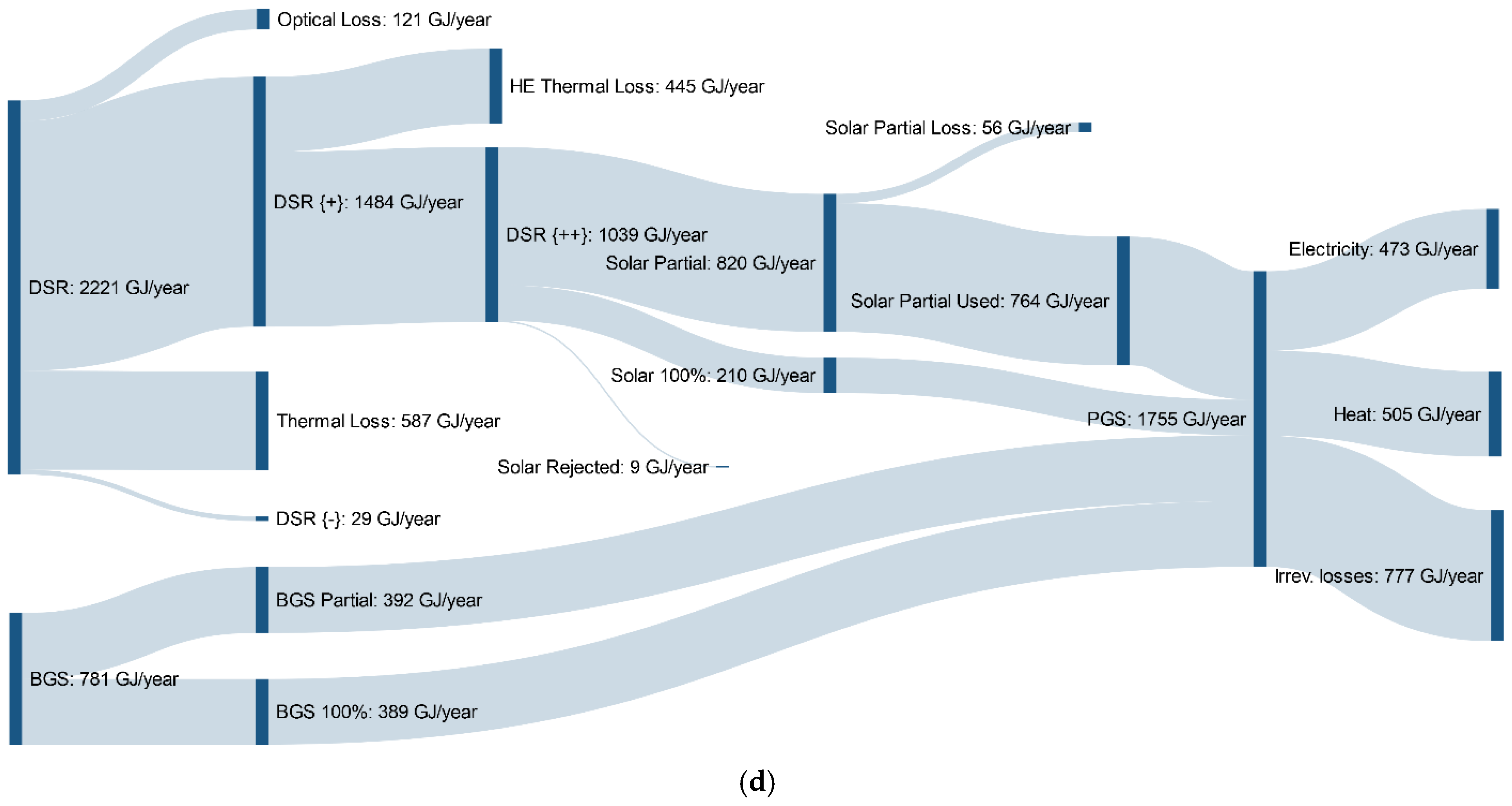
The overall energy balance for an annual operation elucidates comprehensive energy distribution profiles for both power generation systems (
Figure 7). Compared to the hybrid steam turbine systems, the hybrid gas turbine system in both locations requires more solar energy than biogas to compensate thermal losses and realize thermal energy balance (
Figure 7b,d). On the contrary, the steam turbine system has better performance on energy balance (
Figure 7a,c). Particularly at Phoenix, biogas is enough at the net capacity factor of 0.5 to realize the target energy output of 30 kW without need of solar energy input (8421 GJ per year from biogas), which means the net capacity factor can be increased (more than 0.5) for the solar–steam power system to generate more energy at Phoenix.
The analysis in this study is based upon solar thermal energy as a supplemental energy source to facilitate utilization of biofuel–biogas and indirectly improve system power generation performance. As a matter of the fact, the net capacity factor can be significantly increased if solar thermal energy can be directly utilized as a single energy source in thermodynamic cycle for several hours per day (once solar radiation is able to bring the working fluid to desired temperatures for gas and steam turbines). Further studies are needed to explore such scenarios.


