Article

Loading Performance of a Novel Shearer Drum Applied to Thin Coal Seams

1
College of Mechanical & Electrical Engineering, Shandong University of Science & Technology, Qingdao 266590, China
2
College of Transportation, Shandong University of Science & Technology, Qingdao 266590, China
3
School of Information Science and Engineering, Shandong Normal University, Jinan 250014, China
4
Shandong Province Key Laboratory of Mine Mechanical Engineering, Shandong University of Science and Technology, Qingdao 266590, China
*
Author to whom correspondence should be addressed.
Energies 2021, 14(2), 358; https://doi.org/10.3390/en14020358
Submission received: 20 December 2020 / Revised: 6 January 2021 / Accepted: 7 January 2021 / Published: 11 January 2021

Abstract

:
The poor loading performance of shearer drums restricts the development and production efficiency of coal in thin coal seams. Changing operation and structural parameters can improve the drum’s loading performance to some extent, but the effect is not obvious. A two-segment differential rotational speed drum (TDRSD) was proposed after analyzing the drum’s influence mechanism on coal particles. To further reveal the drum’s coal loading principle, the velocity, particles distribution, and loading rate were analyzed. The effect of the matching relationship of the rotational speed and helix angle between the front and rear drum are also discussed. The results show that a lower front drum rotational speed had a positive impact on improving the loading performance, and the loading rate first increases and then decreases with the increase in rear drum rotational speed. The optimal loading performance was obtained in the range 60–67.5 rpm. The front drum’s helix angle had no evident effect on loading performance, and the loading rate increase with the increase in the rear drum’s helix angle. The results provide a reference and guidance for operation parameters selection, structure design, and drum optimization.

1. Introduction

Coal is an important, globally relevant energy source to support industrial production and development and mining it safely and efficiently has been studied extensively [1,2]. As the key equipment in the longwall mining coalface, the shearer’s cutting and traction performance has been investigated [3,4]. With the continuous mining of coal resources, the reserves of thick and extremely thick coal seams that are easy-to-mine have been drastically reduced. Thin coal seams with a wide range of distribution and rich reserves have thus become the focus of coal energy development. Due to the influence of the mining height and geometry structure of equipment in thin coal seams, the coal shearer’s loading performance is extremely poor, causing float coal and the need to be cleaned manually by workers, which harms production efficiency and affects workers’ safety directly. Therefore, thin coal seam mining’s key goals are to improve drum loading performance promoting safety, and efficient exploitation.
The coal loading process of the drum is complex and random. Scholars worldwide first investigated the coal loading performance of drum in the last century, mainly depending on the combination of theoretical derivation and field experiments to study the structural and motion parameters of the drum, that had a potential impact on loading performance, such as helix angle and number of vanes, web depth, rotational and hauling speed, etc. [5,6,7,8]. Among them, [6] gave a guiding suggestion in drum design, i.e., that the wrap angle should be as small as possible to be less than 360°; the higher the number of vanes, the lower the coal loading rate. Ayhan [9] proposed a drum called “Globiod” with a conical hub, tested it underground and found that it can effectively increase the coal loading rate and lump rate. Boloz [10] created a vaneless single-drum shearer with a coal loader. It had been proved that the new shearer could effectively improve the loading efficiency by field test.
With the continuous in-depth research on the drum’s coal loading performance, Liu and Gao [11,12] built a full-scale test bed and utilized it to investigate the drum loading performance. The orthogonal experiment method investigated the conspicuousness of drum rotational speed, helix angle, and hauling speed on the loading performance. Wydro [13] studied the plow filling and thread angle’s influence on the plow head efficiency by using a test bed.
With the development of computer and simulation technology, numerical simulations have become a new and efficient research method. In order to study the complex properties of granular materials in the bulk conveying process, Cundall et al. [14,15] proposed the discrete-element method (DEM), and for the first time modelled the conveying performance of the screw conveyor through DEM [16]. Subsequently, DEM simulation had an application in the field of screw conveying to investigate conveying performance and bulk material conveying [17,18,19,20]. In addition, the DEM was also popular and widely utilized in other fields, such as in the chemical industry [21,22], pneumatic conveying [23,24,25], and rock cutting and crushing [26,27,28,29,30]. Moreover, DEM had been applied in the field of coal shearing [31,32].
The conveying effect of the drum on the cracked coal was to utilize the principle of screw conveying. During the conveying process, the cracked coal particles have the properties of solid materials and exhibit the complex characteristics of fluids. In addition to the above-mentioned methods, other methods include, using numerical simulation in DEM to investigate the drum loading performance, which was reported for the first time [33]. To improve efficiency and reduce costs, many scholars have used DEM to study the coal loading performance of drum [34,35,36], in which, the impact of up cutting and down cutting on loading performance was investigated in [34]. The authors of [35] studied the effect of position relationship and geometric structure of the ranging arm on the drum loading performance. The authors of [36] compared the results of drum loading in laboratory testing and numerical simulation in DEM, which confirmed the feasibility and reliability of DEM in the study of drum loading.
Because of the thin coal seams’ small mining height, the ejection height is not high enough during particle conveying. When the drum has a lower rotational speed, the particles’ insufficient velocity will cause the coal to circulate or accumulate in the gap between the coal face and chain conveyor. In contrast, the increasing drum rotational speed would increase the possibility of particles being thrown into the goaf. This paper theoretically derived the effect of vanes on particles in the conveying process and further proposed a new drum design idea, to improve coal loading performance. With the help of DEM, the matching relationship of the front and rear drum rotational speed, which causes the optimal loading performance, were obtained. Additionally, the matching relationship of the front and rear drums’ helix angle after the optimization was also obtained.

2. Materials and Methods

As the main equipment of the fully mechanized underground mining face, the working mode and supporting equipment of shearer are shown in Figure 1, including the shearer used to cut coal seam and to load the cracked coal, hydraulic roof support used to protect the shearer and workers, and an armored face conveyor (AFC) was used to convey the coal. In particular, the thin coal seams’ thickness is smaller than that in other countries, so the mining approach is different from others. Generally, to ensure that the shearer’s body can move stable along the face of the coal wall, the front drum was used to cut the floor, using the coal ejection loading approach, i.e., cutting direction is from the floor to the roof. Accordingly, the rear drum was worked by the roof, using the coal pushing loading approach, i.e., the cutting direction is from the roof to the floor. Meanwhile, thin coal seam thickness is small, so the cutting and loading mainly rely on the front drum [37]. Therefore, this paper’s research object is conveying and loading the front drum’s performance, whose coal loading approach is ejection.
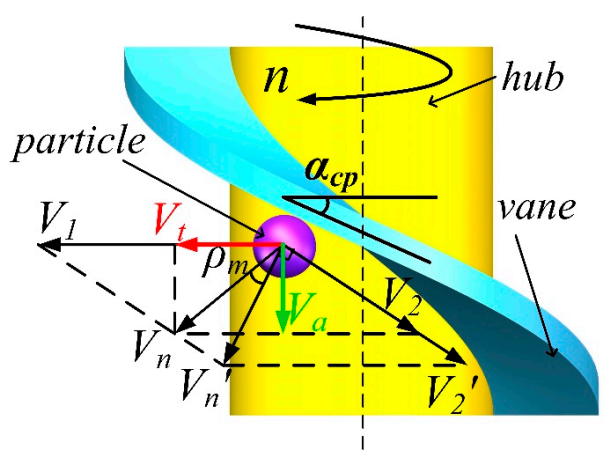
The drum used a spiral blade structure, and its loading mechanism is similar to the principle of screw conveying. Because the movement of coal flow under the action of the spiral blade was complex and random, in order to simplify the research, the theoretical analysis of the coal loading process was carried out, the method of single-body dynamics theory was used, and any particles in contact with the vane was taken as the kinematics research object. Its motion behavior was analyzed, as shown in Figure 2.

2.1. The Kinematic of the Particle under the Action of Helix Vane

Under the action of helix vane, the circumference velocity V1 and the relative motion velocity V2 along vane were obtained, and the absolute velocity Vn along the normal direction of vane was synthesized. Under the negative effect of vane friction, the relative velocity V2 decreased to V2, and the absolute velocity Vn decreased to Vn, with the angle ρm in the normal vane direction as the angle of friction. According to the velocity projection theorem:
V n = V 1 sin α c p cos ρ m
where αcp is the average helix angle of vane, °; ρm is the friction angle between coal and steel, rad.
The circumference velocity V1 of the particles can be obtained by Equation (2):
V 1 = π n D i
where Di is the diameter of somewhere on vane where the particles were located, m; n is the rotational speed of drum, rpm.
The absolute velocity of particles can be obtained from Equations (1) and (2) as:
V n p = n L i cos α c p cos ρ m
where Vnp is the velocity of particle at the average diameter of vane, m/min; Li is the lead of the helix vane, m.
Among them, Li can be expressed by Equation (4) as:
L i = π D cp tan α c p
where Dcp is the average diameter of vane, m.
The tangential velocity Vt and axial velocity Va of the particles can be obtained by decomposing Vnp along the tangential direction and axial direction, respectively.
V t = π n D c p sin α c p sin ( α c p + ρ m ) cos ρ m
V a = π n D c p sin α c p cos ( α c p + ρ m ) cos ρ m
Figure 3a,b show the changes of the Va and Vt of particles with n and αcp of the helix vane, respectively. Figure 3 shows that as the rotational speed increased, particles’ tangential and axial velocity presented an increasing trend, but the change rate of tangential velocity was specifically greater than that of axial velocity. With the increase in the vane’s helix angle, particles’ axial velocity and increased first and then decreased and reached a peak near αcp = 26°. The tangential velocity of particles increased with the increase in the helix angle. Therefore, it can be understood that, although increasing the rotational speed can increase the axial fluidity of cracked coal particles and facilitate the conveying of particles from depths of the coal face. Meanwhile, the rotational speed’s influence on particles’ tangential velocity was more obvious, especially at a larger web depth, which increased the possibility of particles being thrown into the shearer track and reduced the drum’s loading rate.
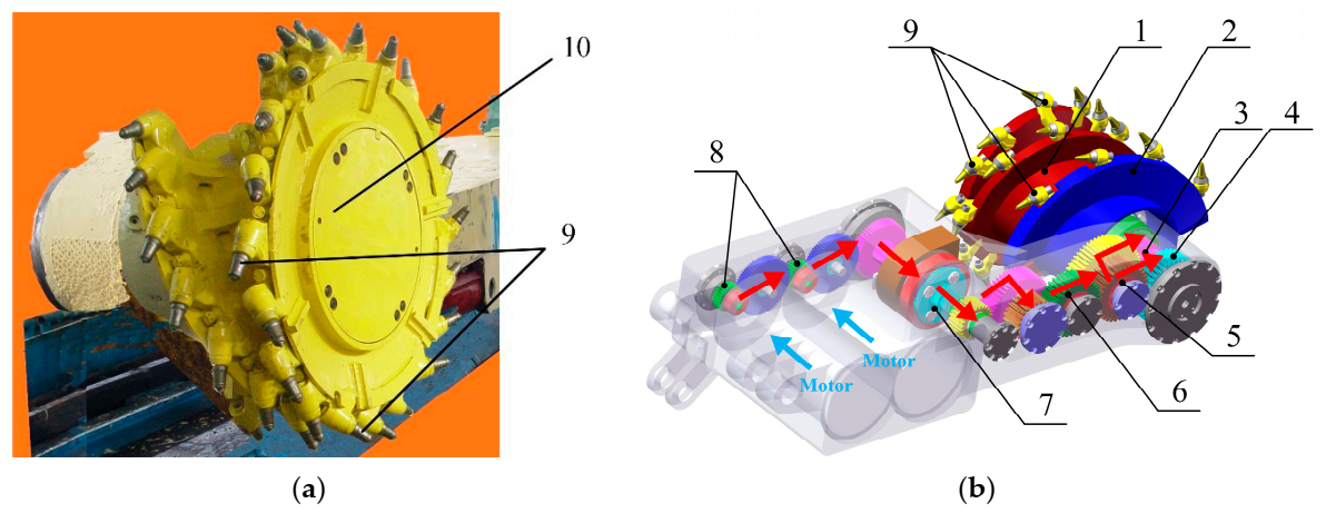
In order to avoid the problems of particles accumulating in the gap area due to insufficient axial speed caused by lower rotational speed, and particles being thrown into the goaf due to higher rotational speed, a two-segment differential rotational speed drum (TDRSD) structure with different rotational speeds installed on the same ranging arm, and its transmission system was designed, as shown in Figure 4b.
The actual drum and TDRSD are shown in Figure 4a,b, respectively. In TDRSD, the cutting unit was driven by a double motor coupling, and the transmission system of the cutting unit was composed of a gear train, including a four-stage spur gear reduction and a one-stage planetary gear reduction. The front drum’s rotational speed was lower than normal, and the rear drum’s rotational speed was higher than normal.

2.2. The Limitation of Coal Flow Speed and Movement Process to Drum Speed

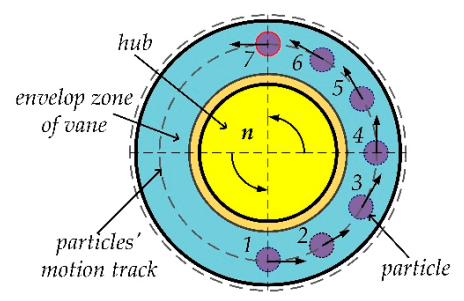
As the coal loading approach was ejection, the drum cutting direction from floor to roof. Therefore, the helix vane started to contact the particle from the bottom of the coal face’s inner side, and particles moved from the endplate to the conveyor. Hypothetically, in the process of conveying, the particles tangential velocity was constant and no radical displacement occurred in the vane envelop area–the theoretical trajectory of the particle is shown in Figure 5. The innermost and bottommost particles were the most difficult to be conveyed out. The particle at position 1 first contacts the vane, and then passes through positions 2, 3, 4, 5, 6 successively under the vane’s action, and finally reached the top of the drum at position 7. The time tz used in the whole moving process can be expressed as Equation (7):
t z = 180 / 360 V t π D c p = π D c p 2 V t
Equation (7) shows that if the particles have moved to position 7, and have not reached the end of the drum, the particle would not be loaded onto the conveyor but would instead be thrown into the goaf as floating coal. Therefore, in combination with Equation (6), in the extreme case, the axial displacement of the particle with the largest section depth in tz, was greater than the web depth J of the drum, which is expressed by Equation (8):
V a t z > J
If Equation (8) was satisfied, the minimum requirements for loading could be achieved. Therefore, Equations (2) and (4)–(6) were incorporated into Equation (8), which can be expressed as Equation (9):
π D c p cos α c p + ρ m 2 sin α c p + ρ m > J
According to Equation (9), the maximum web depth curve with the average helix angle αcp can be drawn, as shown in Figure 6. Figure 6 shows that, with the continuous increase in helix angle, the maximum web depth J that satisfied Equation (9) was continuously reduced. Therefore, to ensure a certain web depth was unchanged, the only approach was to reduce the helix angle, which would cause an increase in the wrap angle. [5] proved that the larger wrap angle had a negative impact on coal loading performance by field tests. Because of the above analysis, based on a differential drum and combined Equation (9), the front drum was far away from the conveyor and with a larger web depth, so a smaller helix angle was adopted; the rear drum was near the conveyor, and with a smaller web depth, so the larger helix angle was utilized.

3. The Establishment of Model and Discrete Element Modeling

3.1. The Theory of Discrete-Element Method

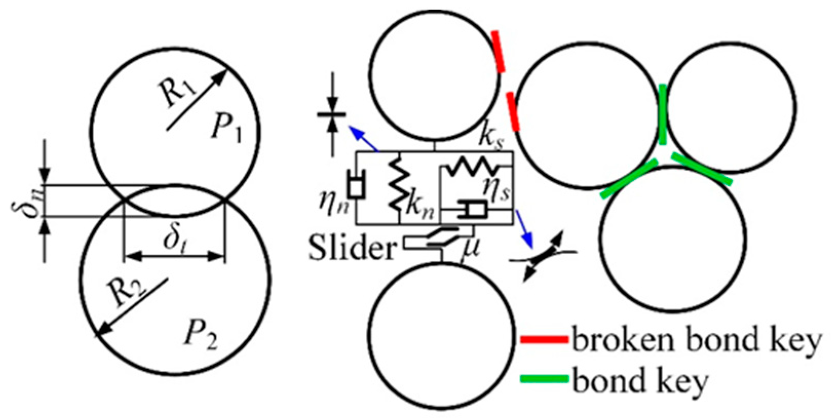
In DEM, the Hertz–Mindlin (HM) no-slip model was the basic model between particles. In order to model the coal face before being crushed, the particles should be glued. Therefore, the Bonded-Particle Model (BPM) [38] was used as the particle bonding model to prevent the coal face from collapsing, as shown in Figure 7. The HM contact and BPM models were expressed as Equations (10) and (11), respectively.
F n = 4 3 E R δ n 3 2 F t = S t δ t
where Fn is the normal stress, N; δn is the normal overlap between particles, m; E* is the equivalent Young’s modulus of particles, MPa; R* is the equivalent radius of particles, m; Ft is the tangential stress, N; St is the tangential stiffness, N/m; δt is the tangential overlap between particles, m:
F n R n F t R t
where Rn is the critical normal stiffness, N; Rt is the critical tangential stiffness, N.

3.2. Model and Calibration of the Particle Shape

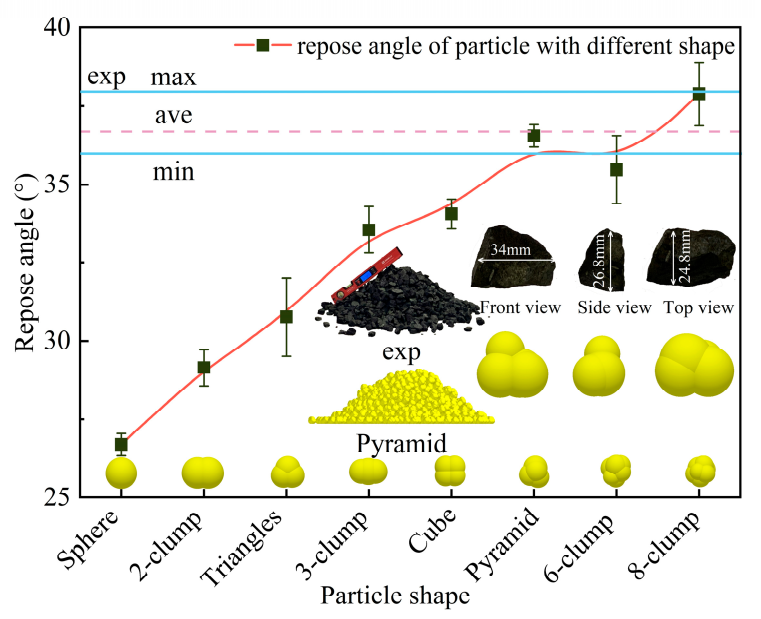
In the DEM numerical modeling, because of the simple ball shape and few contact surfaces between particles, which cause the higher computing efficiency and shorter simulating time, the spherical particle is popular and widely utilized in many engineering fields. However, the spherical particle has a disadvantage and cannot be ignored, that is, the contact between particles is point-to-point contact mode; the sliding friction almost has no effect on the movement of particles. Therefore, there is a fascinating point that the sliding friction coefficient of the spherical particle was generally set to be greater than 1 in DEM, which is unlikely in actual practice, to achieve the consistency of the macro phenomenon [39,40]. The shape has an important impact on the movement of particles [41], and the shape of excavated and cracked coal particles are rarely spherical, so we compared the results of the repose angle between real coal particles and particles with a different shape in DEM, and finally determined the particle shape utilized in DEM modeling. The calibration of particle shape in DEM was taken with the particle calibration method’s repose angle test method [41]. The real friction coefficient between coal–coal and coal–steel measured by [42] was used in DEM. Meanwhile, the dimensions of broken coal particles excavated by thin coal seam shearer are 25–40 mm, so the particles with approximately uniform dimensions around 30 mm were selected to take laboratory’s repose angle experiment. The experiment repose angle was obtained through multiple tests and measurements. Comprehensively considering the computational cost and accuracy of numerical results, the dimensions of particles in DEM was also determined to around 30 mm, and particles’ dimensions and the comparison of the repose angle between the experiment and different particle shape in DEM is shown in Figure 8.
Figure 8 shows that the repose angle of pyramid, six-clump, and eight-clump particles in DEM were similar to the experimental situation, which means that the more spheres that make up the particles, the more the real coal shape could be simulated, and the simulation results were closer to the real situation. However, due to the more spherical surface of particles clumps, the lower the calculation efficiency, it fell within an acceptable error range; using pyramid particles as the shape in modeling can get an accurate result. The materials parameters in DEM are shown in Table 1.

3.3. Establishment of DEM Model

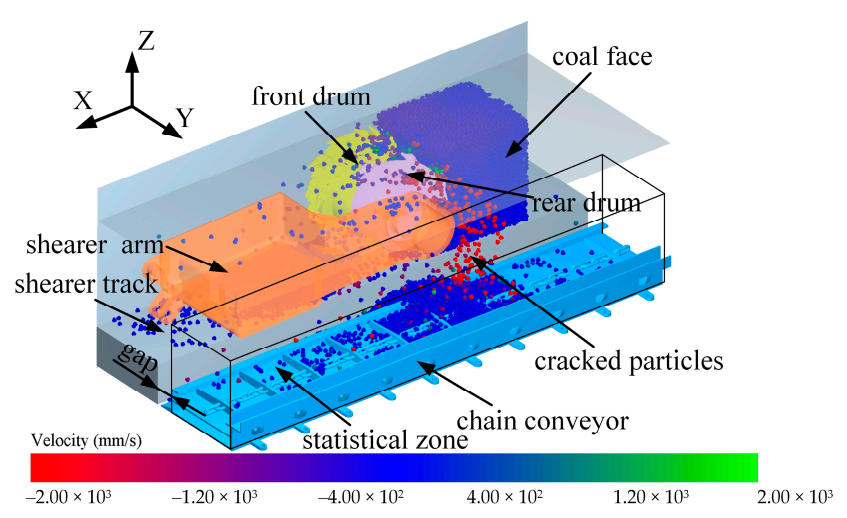
According to the schematic of the shearer working condition in Figure 1, the front drum, rear drum, ranging arm, conveyor and bonded coal face were built using DEM, as shown in Figure 9. The model was simplified to improve computing efficiency, and the hydraulic support group, which have on effect on the final results and was not built into the model. The kinematic and structural parameters of the differential drum were shown in Table 2. To further study the matching relationship of helix angle between the front and rear drum, the specific geometric structure parameters of variable helix angle were given in Table 3.

4. Results and Discussion

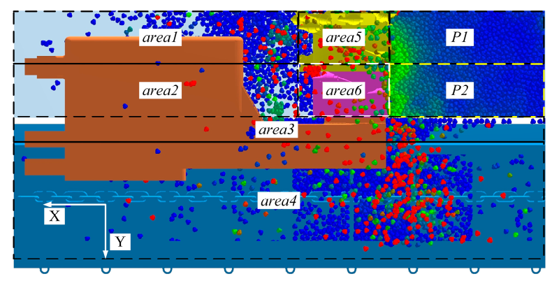
To investigate the effect of differential drum on shearer loading performance and the coal loading mechanism of TDRSD, the coal face was divided into two equal parts, P1 and P2, according to the different web depth. P1 was far away from the conveyor with a larger web depth and P2 was near the conveyor. Meanwhile, to investigate the distribution of the particles under the action of TDRSD, the distribution area was divided into six statistical areas: the goaf of the shearer track was divided into two areas, which were area 1 and area 2, area 1 and P1 were parallel area 2 and P2 were parallel; the gap between coal face and conveyor was area 3; the conveyor was area 4,which is the actual effective loading area; area 5 and area 6 were the front drum and rear drum, respectively, shown in Figure 10. The rotational speed of the front and rear drums were represented by nF and nR, respectively.

4.1. The Effect of TDRSD on Particle Velocity

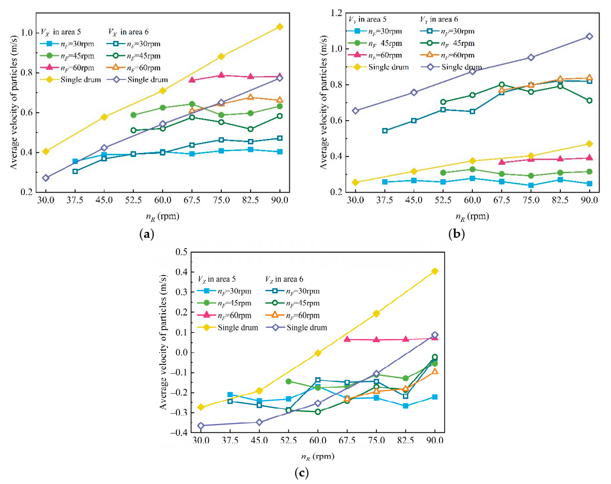
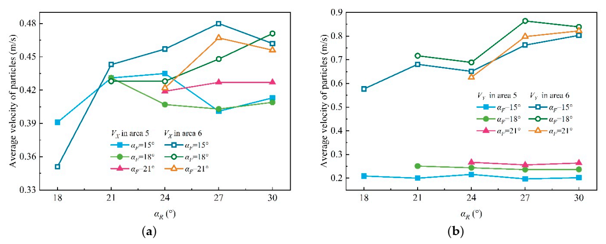
Figure 11 shows that, in area 5, with the increase in nR, the changing velocity of particles in the X-direction (VX) was not obvious under the same nF; whereas the VX of particles increased slightly with the increase in nR, in area 6 which illustrated that the increase in nR had no obvious effect on the velocities of particles in the front drum in the X-direction. Figure 11a shows that the VX of particles in area 5 was significantly greater than that in area 6; the main cause that led to this result would be the endplate’s existence in area 5. The friction of vanes had no impact on the particles excavated by picks of the endplate, so the particles could get a larger tangential velocity, which causes a bigger VX of particles in area 5 than in area 6.
There was a more pronounced difference of particle velocity in Y-direction (VY) between particles in area 5 and area 6, and the VY in area 6 was approximately two times bigger than that in area 5 with the same rotational speed condition. In the initial cutting phase, the screw vanes had no impact on the particles excavated by picks of endplate; just like the above, particles hardly obtained the axial velocity. Moreover, the particle velocities of a single drum were more significant than that of TDRSD under the same rotational speed, and the primary cause was that the rear drum adopted a single screw vane, while the front drum adopted a structure of double vanes. In the conveying process, the particles were conveyed from the front drum to the rear drum and accumulated in the rear drum’s envelop zone, which caused the decreasing of particles velocities in the axial direction of TDRSD.
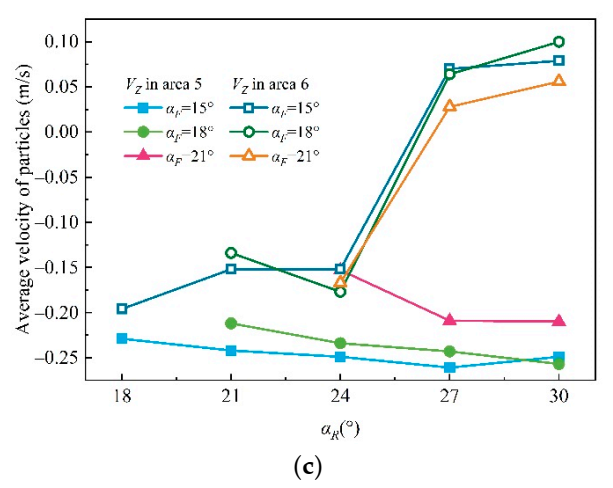
Comparing the Z-direction (VZ) velocity between particles in area 5 and area 6, it can be observed that VZ in area 5 was greater than that in area 6, especially under greater rotational speed conditions. The main reason was that the rear drum adopted a single vane structure, and the particles were less agitated by the vanes, so the value of VZ in area 6 was less than that in area 5.
By comprehensively analyzing and comparing Figure 11a,c, we see that with the increase in nR, the VX of particles in area 6 increases slightly, while the VZ increases intensively. The main reason causing this phenomenon is that the cutting direction was from floor to roof, with the drum rotation axis’s height as the criterion. The vanes acted on the particles whose position was lower than the horizontal height of rotation axis of drum, the component in the tangential velocity in the X-direction was the same as the hauling direction. However, for the particles higher than the criterion height, the X direction’s tangential velocity was precisely the opposite. Considering that the number of particles in the upper and lower parts was basically the same, the X-direction’s velocity was opposite, so the rotational speed’s changed had no evident impact on velocities in the X-direction.

4.2. The Distribution of Particles under the Effect of TDRSD

Figure 12 shows particles distribution results in different statistical zones with different rotate speed matching between the front and rear drums. The value of P1 was greater than the value of P2, which is about six times the value of P2. The front drum was responsible for coal wall P1, and rear drum was responsible for the rest coal wall P2, which can explain the above result. The particles flow conveyed axially under the action of screw blades, theoretically speaking, it is impossible for particles belonging to P2 to appear in area 1. The main reason for the interesting phenomenon could be that the particles belonging to P2 were thrown and stacked in area 2, and the number of particles increased until the stacking angle was greater than the repose angle, leading to some particles sliding into area 1. In the same nF, the value of P1 decreases first and then increases with the increase in nR; the bottom point can be found in the range 60–67.5 rpm. The drum’s overall conveying efficiency was not high with a smaller nR, and the particles belonging to P1 were packing in the front drum, resulting in a larger value of P1; the conveying efficiency increase with the increase in nR, which made the P1 decrease. The value of P1 increases again because particles were thrown into area 1 with nearly horizontal movement under the action of evident tangential effect when the particles were conveyed form the front drum to the rear drum. In the same nR, the value of P1 increase with the increase in nF, which indicated that a lower nF had a positive influence on particles remaining in the drum envelop area during the conveying process and reducing the probability of being float coal.
The change rule of the value of P1 and P2 with nR in area 2 is shown in Figure 12b. In statistical area 2, the value of P1 was slightly greater than that of P2, and its change rule with nR was similar to P2. The value of P1 in area 2 decreased obviously compared to that in area 1, and the value of P2 increased slightly. The value of P1 had an increasing trend with the increasing nF; nF had almost no impact on the value of P2. The primary reason for that was the particles belonging to P1 was influenced by the coupling effect of tangential and axial, and the bigger the nF was, the more intense the impact was.
Since the particles belonging to P2 were closer to statistical area 3, the particles were more likely distributed in area 3, so the value of P2 was greater than that of P1, as indicated in Figure 12c. The value of P1 and P2 in statistical area 3 had no evident regularity with the change of nR. The main reason for the above results was that the particles were affected by a combination of two factors: (1) the particles belonging to goaf slid into area 3, or the particles thrown to the goaf area and blocked by the ranging arm, then distributed in area 3; (2) the axially moving particles failed crossing the area 3 because of the insufficient ejection speed and stayed in the statistical area 3. The movement of particles was mainly influenced by factor (2) when the rotation speed was low, so the value of P1 and P2 was relatively bigger; factor (1) was gradually strengthened with the increase in the rear drum’s rotation speed. In comparison, the lower rotation speed had a more evident impact on the value of P1 and P2 in area 3.
Figure 12d indicated the value of P1 and P2 under the different rotational speed matching in area 4, namely, the effective statistical area, respectively. Considering that the particles of P2 were close to the conveyor, so P2 was obviously bigger than P1, correspondingly, about 1.3 times of P1 value. Meanwhile, the change rule of P1 and P2 with nR was similar, respectively. With the increase in nR, the value of P1 and P2 in area 4, were both first increases and then decreased under the same nF circumstance. Furthermore, with the increase in nF, the value of P1 and P2 were both had a decreasing trend, and the decline amplitude of P1 was more evident than that of P2.
Figure 13 showed the distribution and percentage of particles of P1 in area 1 and area 4 with a constant nR, respectively. By keeping the nR constant in different simulation cases, the influence of different nF on particles’ motion behavior in P1 was investigated, and the loading mechanism of different rotational speed matching was revealed further. As indicated in Figure 13a, the value of P1 in area 1 had an evident difference with the different nF under the condition of nR was 60, 75, and 90 rpm, respectively. The P1 value in area 1 increased with the increase in nF in the same nR; the reason for that was the higher of nF was, the more pronounced the effect of front drum throwing particles into goaf could be approximately considered, which was consistent with the previous conclusion. An interesting point was found in nR = 75 rpm; the P1 value of nF = 45 rpm was slightly greater than that of nF = 60 rpm, which was contray to previous conclusions. The main reason for this phenomenon may be that the structure of the vane in the rear drum was a single vane, while the front drum was a double vane; therefore, the single drum of the rear drum with nR = 75 rpm could be equivalent to a double vane with nR = 37.5 rpm, which was greater than the front drum nF = 30 rpm and was the closest to the front drum nF = 45 rpm. As mentioned above: the circumstance of nR was greater than nF, the screw vane of the rear drum will rotate to the anterior of the front drum vanes, leading to a larger space behind the front drum, and the particles flowed axially to envelop zone of the rear drum. Under the equivalent conditions, nR was less than that of nF, especially the rotational speed difference between nF and nR was not obvious, the vanes of front drum and rear drum had a considerable part of the coincidence area, where the vanes of rear drum blocked particles flow, and the axial velocity of particles decreased sharply. It can be seen through the velocity vector that even the direction of some particles in the axial direction was reversed, as indicated in Figure 14. Figure 13b shows that nF = 30 or 45 rpm, nR increased from 60 rpm to 75 rpm, and the change of P1 value in area 4 was not significant, which proved that the influence of the rear drum on particles that far away from the conveyor was not evident. The main reason for the above was that the particles conveyed from the front drum to the rear drum’s envelop zone, were packed at the bottom of the rear drum mostly, although the rear drum with a higher nR hardly impacted on the particles at the bottom.

4.3. The Influence of Rotational Speed Matching between the Front and Rear Drums on the Loading Rate

Based on the analysis above, the rotational speed had an important impact on particle velocity, motion path, and particle distribution; consequently, the influence of rotational speed matching between the front and rear drum on loading rate was also investigated.
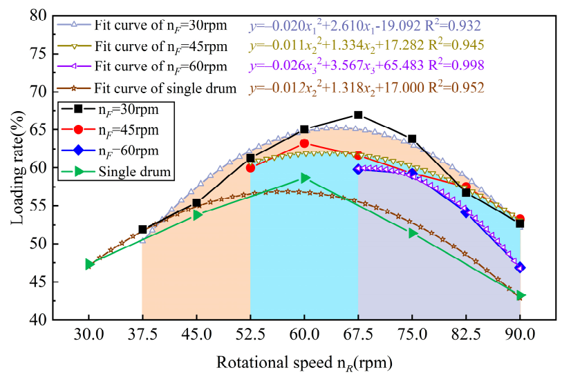
As indicated in Figure 15, in single drum cases, the loading rate increases first and then decreases with the increase in rotational speed and obtained a peak value in n = 60 rpm. The loading rate of TDRSD was better than that of a single drum. The loading performance of TDRSD also showed strong regularity as the nF gradually increased. With the increase in nF, the improvement effect of the loading rate of the TDRSD was gradually reduced compared with the single drum. In the cases of nF = 30 rpm, the loading rate first increased and then decreased with the increase in nR and obtained the optimal loading performance in nR = 67.5 rpm. In the case of nF = 45 rpm, the change law of loading rate of TDRSD still increased first and then decreased with the increase in nR; as indicated in Figure 15, there was an optimal loading performance in the range 60–67.5 rpm. In the case of nF = 60 rpm, the loading rate gradually decreased with the increase in nR. Based on the influence of the matching relationship between the front and rear drums on the loading performance, although the nF was not the same, the optimal loading performance of TDRSD was in the range nR = 60–67.5 rpm. The lower nR may cause two effects on the particles: (1) the particles’ axial fluidity was poor, and the particles were packed in area 3 instead of being thrown into the conveyor because the axial velocity was not enough; (2) the lower nR cannot provide enough ejection velocity for the particles to cross the shearer arm, so they were blocked by the arm and rebound back to area 2 [34], causing the lower loading rate. The negative effects of the above two conditions on particle flow were continuously decreased with the increase in nR, and the particles in the conveyor gradually increased, so the loading rate was gradually increased, correspondingly. In the case of nR continuously increasing, it can be seen from the above analysis that the tangential throwing effect of the drum for particles was significantly stronger than the axial conveying effect, so the particles were more thrown into the shearer track and became float coal, causing the loading rate decreased.
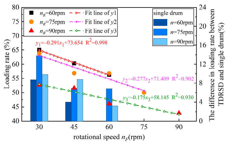
Figure 16 showed the difference of coal loading rate between the single and TDRSD under the same nR (60, 75, and 90 rpm). Figure 13b indicated that the value of P1 in area 4, namely, the loading rate of particles in P1. Comparing Figure 13b and Figure 16, and combining with Table 4, the particles in the P1 area were extremely significant factors affecting the difference of coal loading rate between single and TDRSD in the conveying process. Meanwhile, the above analysis was verified again; in the process of particles’ conveying, the lower nF had a positive impact on particles remaining in the envelope zone, and properly increasing nR was conducive to enhancing the particles’ ejection effect. Through the overall analysis of the matching relationship of rotational speed between the front and rear drum, in the view of particles loading performance, the front drum should adopt a lower rotational speed as far as possible, and the rear drum rotational speed should be guaranteed in the range 60–67.5 rpm, which allows the drum to work at the optimal loading performance.

4.4. The Influence of Helix Angle Matching between the Front and Rear Drum on Particle Velocity

Based on the TDRSD, the influence of helix angle matching between the front and rear drum on loading performance was investigated to optimize the loading performance of the drum. The investigation was performed at a single drum rotational speed of 60 rpm, and the αF and αR were the helix angle of the front and rear drum, respectively.
Figure 17 indicated the particles velocity in three-directions with different helix angle matching. Figure 17a–c show the velocities in the X, Y, and Z-direction, respectively. It was self-evident in Figure 17b that the velocities difference between area 5 and area 6 in the Y-direction was more evident with the increase in nR. Meanwhile, with the increase in αR, the change law of particles axial particles was homogeneous to that of the theoretical axial velocity of particles in Figure 3a, and the axial velocity of particles gradually increased with the increase in αR. In addition, the velocities of the particles in the X and Z-direction in Figure 17a,c, namely, the particles ejection velocity increased with the increase in αR, which had a positive impact on improving loading performance. The front drum adopted three kinds of vanes with a different helix angle of 15°, 18°, and 21°, respectively. Considering the smaller the helix angle, the larger the vanes’ wrap angle was, and the more pronounced the effect of the vanes was on the particles. Therefore, although the αF was different, the particle’s velocity in the X-direction in area 5 did not change obviously under the different αF. This was because a larger αF can cause a larger particle velocity, but in the cases of a smaller αF, there were more contacts between vanes and particles, so the change of αF was not evident for the velocity change of particles in area 5.

4.5. The Distribution of Particles under the Different Helix Angle Matching

The distribution of particles in P1 and P2 in different statistical areas are shown in Figure 18. Figure 18a shows that the value of P1 decreased with the increase in αF when the αF was less than 24°. In addition, the P1 value in area 1 was greater than that before optimization (αF = 24°), and the primary reason for that was the helix angle of the front drum was small, which lead to a larger wrap angle, which further leads to the larger coincidence area of double-vane. The particles did not flow easily or axially within the front drum’s envelop zone and became a circulation coal. Therefore, the P1 value in area 1 increased with the decrease in αF.
The rear drum was responsible for particles in P2, so the helix angle of rear drum vanes had a more noticeable effect on P2 value in area 2, as indicated in Figure 18b. In the cases of the same αF, the P2 value decreased with the increase in αR. Moreover, the increase in αF had a slight impact on P2 value in area 2. With the increase in αF, the value of P2 had a trend of decreasing. Meanwhile, the P1 value decreased with the increase in αR under the conditions of the same αF.
In Figure 18c, the αR had a significant effect on the value of P2 in area 3, but not for the P1 value. By comparing with Figure 3, the influence of the helix angle on the particles axial velocity was not evident, but the change of tangential velocity was quite evident. Combined with the analysis in Figure 15, the P2 value decreased gradually with the increase in αR in Figure 18c was explained. With the increase in helix angle, the particles were obviously ejected by the screw vanes in the rear drum. When conveyed out from the drum outlet, the particles obtained a larger velocity in the opposite direction of gravity, and had a longer movement time in the air. Therefore, the particles can cross area 3 and load onto the conveyor; as a result, the P2 value decreased with the increase in αR in area 3. Comparing Figure 18c,d, the value of P2 in area 3 decreased with the increase in αR, which lead to the P2 value in area 4 increased with the increase in αR.

4.6. The Influence of the Helix Angle Matching between the Front and Rear Drum on Loading Performance

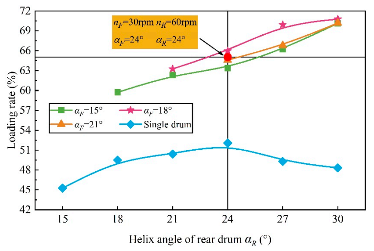
The change curves of the loading rate under the helix angle matching between the front and rear drum are shown in Figure 19. In the cases of different αF, the loading rate increased with the increase in αR. Moreover, the increasing trend of the loading rate of helix angle matching drum was similar, whereas the changing trend of single drum loading rate was first increased and then decreased with the increase in the helix angle. As mentioned above, the particles axial velocity decreased with a smaller helix angle, and the tangential velocity will play a leading role. The possibility of particles being thrown into the goaf increased. With the increase in the helix angle, the negative effect of wrap angle on particles gradually decreased, and the loading rate increased. With the continuous increase in the helix angle, the wrap angle’s influence on particles’ tangential velocity increased significantly. As the value of αF was large and the wrap angle was small, which was not conducive to particles remaining in the envelope zone of the screw vanes, resulting in the weakening of the drum’s conveying capacity, and further leading to the decline of the drum loading performance.
Although the αF was different, the differences of loading rate were not apparent under the condition of the same αR, which proved that compared with the change of αR, the impact of αF on loading performance was not noticeable. Therefore, in the matching relationship and helix angle design, the smaller αF should be selected. The optimal loading performance was obtained in the cases of αF = 18° and αR = 30°. The result was basically consistent with the relationship between the theoretical web depth and helix angle in Figure 6. The theoretical maximum web depth was 800 mm at α = 18°, while in the DEM simulation, the web depth of the front drum was 850 mm, in which the end plate was about 50 mm, so the envelop zone of screw vanes was about 800mm; the theoretical maximum web depth was 425 mm at αcp = 30°, while in the DEM simulation, the web depth of rear drum was 400 mm. Therefore, the simulation results and theoretical calculation results had high consistency.
Considering Figure 15 and Figure 19, Table 5 and Table 6, the rotational speed matching relationship between front and rear drum had a more significant impact on loading performance than the helix angle matching. Considering the loading performance, in the process of drum design and rotational speed matching of TDRSD, the nF should be kept at about 30 rpm, and that of nR should be kept in the range 60–67.5 rpm. Based on the TDRSD, the helix angle matching between the front and rear drum was optimized, and the αF should be about 18° and the value of αR should be larger for optimal loading performance.

5. Conclusions

To improve the drum’s loading performance, a new design for TDRSD, and a design scheme for its transmission system were proposed. With the discrete-element method’s help, the coal loading performance of the TDRSD under different working conditions was investigated. To improve the accuracy of the simulation and the reliability of the results, the particle shape used in DEM was calibrated in a laboratory via packing tests. The rotational speed matching between the front and rear drum under the optimal loading performance was obtained through the simulation, and the helix angle matching between the front and rear drum was also investigated. Aiming to improve the thin coal seam shearer’s poor loading performance, we proposed a new drum design idea. The research results can provide guidance and reference for designers to some extent. The conclusions are as follows:
(1)
In the TDRSD, the front drum’s lower rotational speed positively impacted particle conveying. The particles velocity in X-direction had no obvious change with the increase in rotational speed of the rear drum, while the velocity in Y and Z-direction had an obvious increasing trend, which made the particles obtain the ability to cross the gap and played a positive role in particle loading.
(2)
The front drum should adopt a lower rotational speed, and the loading performance first increased and then decreased with the increase in the rear drum’s rotational speed. When the front drum’s rotational speed was 30 rpm, and the rear drum’s rotational speed was 60–67.5 rpm, the optimal loading performance was obtained. The optimal loading rate was 66.94%, which is more than 10% higher than that under single drum condition.
(3)
The relationship between the helix angle of screw vanes and the maximum web depth was theoretically deduced, and the relationship was optimized based on rotational speed matching. The influence of the front drum’s helix angle on the coal loading performance was not obvious, and the coal loading rate increased continuously with the increase in rear drum’s helix angle. After optimization, the optimal loading performance was obtained in the cases of the front drum’s helix angle was 18° and of the rear drum was 30°, and the coal loading rate was increased by 3.83% compared with TDRSD.
(4)
According to the influence of rotational speed matching and helix angle matching on particles loading performance of the drum, the influence degree of the rotational speed matching between the front and rear drum on loading performance was more obvious than that of helix angle matching, which is the decisive factor affecting the coal loading performance of the drum.

Author Contributions

Conceptualization, K.G. and Z.L.; methodology, K.G. and X.Z.; software, X.Z. and L.S.; formal analysis, K.G. and Q.Z.; writing—original draft preparation, K.G. and X.Z.; writing—review and editing, L.S., Q.Z. and Z.L.; funding acquisition, K.G. All authors have read and agreed to the published version of the manuscript.

Funding

This research was funded by the National Natural Science Foundation of China (Grant No. 51704178), the Natural Science Foundation of Shandong Province (Grant No. ZR2017MEE034), the Open Foundation of Shandong Province Key Laboratory of Mine Mechanical Engineering (Grant No. 2019KLMM102), and the Project of Shandong Province Higher Educational Young Innovative Talent Introduction and Cultivation Team (Performance enhancement of deep coal mining equipment).

Conflicts of Interest

The authors declare no conflict of interest. The funders had no role in the design of the study; in the collection, analyses, or interpretation of data; in the writing of the manuscript, or in the decision to publish the results.

References

  1. Dong, Y.; Di, J.; Wang, X.; Xu, L.; Yang, Z.; Guo, X.; Li, M. Dynamics Experimental Study on Treatment of Acid Mine Drainage by Bacteria Supported in Natural Minerals. Energies 2020, 13, 439. [Google Scholar] [CrossRef] [Green Version]
  2. Wang, K.; Huang, Y.; Gao, H.; Zhai, W.; Qiao, Y.; Li, J.; Ouyang, S.; Li, W. Recovery Technology of Bottom Coal in the Gob-Side Entry of Thick Coal Seam Based on Floor Heave Induced by Narrow Coal Pilar. Energies 2020, 13, 3368. [Google Scholar] [CrossRef]
  3. Ma, D.J.; Zhang, X.; Wan, L.R.; Zeng, Q.L.; Ge, H.E. Dynamics Analysis of Shearer Traction Unit Considering the Longitudinal Swing. Energies 2020, 13, 5293. [Google Scholar] [CrossRef]
  4. Li, X.F.; Wang, S.B.; Ge, S.R.; Malekian, R.; Li, Z.X. Investigation on the influence mechanism of rock brittleness on rock fragmentation and cutting performance by discrete element method. Measurement 2018, 113, 120–130. [Google Scholar]
  5. Booker, C.M. Theoretical and practical aspects of cutting and loading by shearer drums. Aust. J. Coal Min. Technol. Res. 1983, 3, 1–24. [Google Scholar]
  6. Ludlow, J.; Jankowski, R.A. Use low shearer drum speeds to achieve deeper coal cutting. Min. Eng. 1984, 36, 251–255. [Google Scholar]
  7. Hurt, K.G.; Mcstravick, F.G. High performance shearer drum design. Colliery Guardian. 1988, 236, 425–429. [Google Scholar]
  8. Peng, S.S.; Chang, H.S. Longwall Mining; John Wiley and Sons: New York, NY, USA, 1984. [Google Scholar]
  9. Ayhan, M.; Eyyuboglu, E.M. Comparison of globoid and cylindrical shearer drums’ loading performance. J. S. Afr. Inst. Min. Metall. 2006, 106, 55–56. [Google Scholar]
  10. Boloz, L. Unique project of single-cutting head longwall shearer used for thin coal seams exploitation. Arch. Min. Sci. 2013, 58, 1057–1070. [Google Scholar]
  11. Liu, S.Y.; Du, C.L.; Zhang, J.J.; Jiang, H. Parameters analysis of shearer drum loading performance. Min. Sci. Technol. 2011, 5, 621–624. [Google Scholar] [CrossRef]
  12. Gao, K.D.; Xu, W.B.; Jiang, S.B.; Du, C.L. Factors affecting thin coal seam shearer drum coal-loading performance by a model test method. J. Cent. South Univ. 2019, 26, 1619–1636. [Google Scholar] [CrossRef]
  13. Wydro, T. Influence of the plow filling and thread angle onto the plow head efficiency. Arch. Min. Sci. 2015, 60, 143–156. [Google Scholar]
  14. Cundall, P.A. Computer model for simulating progressive large scale movements in blocky rock systems. In Proceedings of the Symposium of the International Society of Rock Mechanics, Nancy, France, 4–6 October 1971; Volume 1, pp. 2–8. [Google Scholar]
  15. Cundall, P.A.; Strack, O.A. Discrete numerical model for granular assemblies. Geotechnique 1979, 29, 47–65. [Google Scholar] [CrossRef]
  16. Shimizu, Y.; Cundall, P.A. Three-Dimensional DEM simulations of bulk handling by screw conveyors. J. Eng. Mech. 2001, 127, 864–872. [Google Scholar] [CrossRef]
  17. Owen, P.J.; Cleary, P.W. Prediction of screw conveyor performance using the Discrete Element Method (DEM). Powder Tech. 2009, 193, 274–288. [Google Scholar] [CrossRef]
  18. Orefice, L.; Khinast, J.G. DEM study of granular transport in partially filled horizontal screw conveyors. Powder Tech. 2017, 305, 347–356. [Google Scholar] [CrossRef]
  19. Pezo, M.; Pezo, L.; Jovanović, A.P.; Terzic, A.; Andric, L.; Loncar, B.; Kojic, P. Discrete element model of particle transport and premixing action in modified screw conveyors. Powder Tech. 2018, 336, 255–264. [Google Scholar] [CrossRef]
  20. Wang, S.Y.; Li, H.L.; Tian, R.C.; Wang, R.C.; Wang, X.; Sun, Q.J.; Fan, J.W. Numerical simulation of particle flow behavior in a screw conveyor using the discrete element method. Particuology 2018, 43, 137–148. [Google Scholar] [CrossRef]
  21. He, S.Y.; Guan, J.Q.; Pinson, D.; Yu, A.B.; Zhou, Z.Y. A Discrete Element Method Study of Monodisperse Mixing of Ellipsoidal Particles in a Rotating Drum. Ind. Eng. Chem. Res. 2020, 59, 12458–12470. [Google Scholar] [CrossRef]
  22. Kuang, S.B.; Li, K.; Yu, A.B. CFD-DEM Simulation of Large-Scale Dilute-Phase Pneumatic Conveying System. Ind. Eng. Chem. Res. 2020, 59, 4150–4160. [Google Scholar] [CrossRef]
  23. Li, J.P.; Zhou, F.; Yang, D.L.; Yu, B.C.; Li, Y.Z. Effect of swirling flow on large particle pneumatic conveying. Powder Technol. 2020, 362, 745–758. [Google Scholar] [CrossRef]
  24. Portnikov, D.; Santo, N.; Kalman, H. Simplified model for particle collision related to attrition in pneumatic conveying. Adv. Powder Technol. 2020, 31, 359–369. [Google Scholar] [CrossRef]
  25. Olaleye, A.K.; Shardt, O.; Walker, G.M.; Van den Akker, H.E. Pneumatic conveying of cohesive dairy powder: Experiments and CFD-DEM simulations. Powder Technol. 2019, 357, 193–213. [Google Scholar] [CrossRef]
  26. Zhu, X.H.; Luo, Y.X.; Liu, W.J. The rock breaking and ROP increase mechanism for single-tooth impact cutting using DEM. Pet. Sci. 2009, 16, 1134–1147. [Google Scholar] [CrossRef] [Green Version]
  27. Zhao, L.J.; Jin, X.; Liu, X.H. Numerical research on wear characteristics of drum based on discrete element method (DEM). Eng. Fail. Anal. 2019, 109, 104269. [Google Scholar] [CrossRef]
  28. Zhang, G.Z.; Dang, W.G.; Herbst, M.; Song, Z.Y. Complex analysis of rock cutting with consideration of rock-tool interaction using distinct element method (DEM). Geomech. Eng. 2020, 20, 421–432. [Google Scholar]
  29. Zheng, K.H.; Qiu, B.J.; Li, J.P.; Gao, K.D. 3D XCT Mesostructure Characterization and Image-Based Discrete Element (DE) Modelling of Failure Patterns in Coal Gangue Particles (CGPs). Complexity 2019, 2019, 4021368. [Google Scholar] [CrossRef] [Green Version]
  30. Zhao, L.J.; Liu, H.M.; Zhou, W.C. A study on the dynamic transmission law of spiral drum cutting coal rock based on ANSYS/LS-DYNA simulation. Complexity 2019, 2019, 1482051. [Google Scholar] [CrossRef]
  31. Liu, S.F.; Lu, S.F.; Wan, Z.J.; Zhang, H.W.; Xing, K.K. Numerical simulation of induced cutting in deep coal. R. Soc. Open Sci. 2019, 6, 190308. [Google Scholar] [CrossRef] [PubMed] [Green Version]
  32. Li, X.F.; Wang, S.B.; Ge, S.R.; Malekian, R.; Li, Z.X.; Li, Y.F. A study on drum cutting properties with full-scale experiments and numerical simulations. Measurement 2018, 114, 25–36. [Google Scholar] [CrossRef] [Green Version]
  33. Gao, K.D.; Du, C.L.; Fu, L.; Jiang, H.X. Effect of mining face angle on drum loading performance using discrete element method. Int. J. Earth Sci. Eng. 2014, 7, 41–51. [Google Scholar]
  34. Gospodarczyk, P. Modeling and simulation of coal loading by cutting drum in flat seams. Arch. Min. Sci. 2016, 61, 365–379. [Google Scholar] [CrossRef]
  35. Gao, K.D.; Du, C.L.; Dong, J.H.; Zeng, Q.L. Influence of the drum position parameters and the ranging arm thickness on the coal loading performance. Minerals 2015, 5, 723–736. [Google Scholar] [CrossRef]
  36. Gao, K.D. Feasibility of drum coal loading process simulation using three-dimension discrete element method. Electron. J. Geotech. Eng. 2015, 20, 5999–6007. [Google Scholar]
  37. Gao, K.D.; Zhang, X.D.; Sun, L.Q.; Zeng, Q.L.; Jiang, K. Complex Effects of Drum Hub Forms and Structural Parameters on Coal Loading Performance. Complexity 2020, 2020, 7036087. [Google Scholar] [CrossRef]
  38. Potyondy, D.O.; Cundall, P.A. A bonded-particle model for rock. Int. J. Rock Mech. Min. Sci. 2004, 41, 1329–1364. [Google Scholar] [CrossRef]
  39. Coetzee, C.J. Calibration of the discrete element method. Powder Technol. 2017, 310, 104–142. [Google Scholar] [CrossRef]
  40. Markauskas, D.; Kacianauskas, R. Investigation of rice grain flow by multi-sphere particle model with rolling resistance. Granul. Matter 2011, 13, 143–148. [Google Scholar] [CrossRef]
  41. Coetzee, C.J. Calibration of the discrete element method: Strategies for spherical and non-spherical particles. Powder Tech. 2020, 364, 851–878. [Google Scholar] [CrossRef]
  42. Fu, L. Study on Cutting and Conveying Performance of Novel Auger Miner Drilling Tool. Ph.D. Thesis, China University of Mining and Technology, Xuzhou, China, 2016. [Google Scholar]
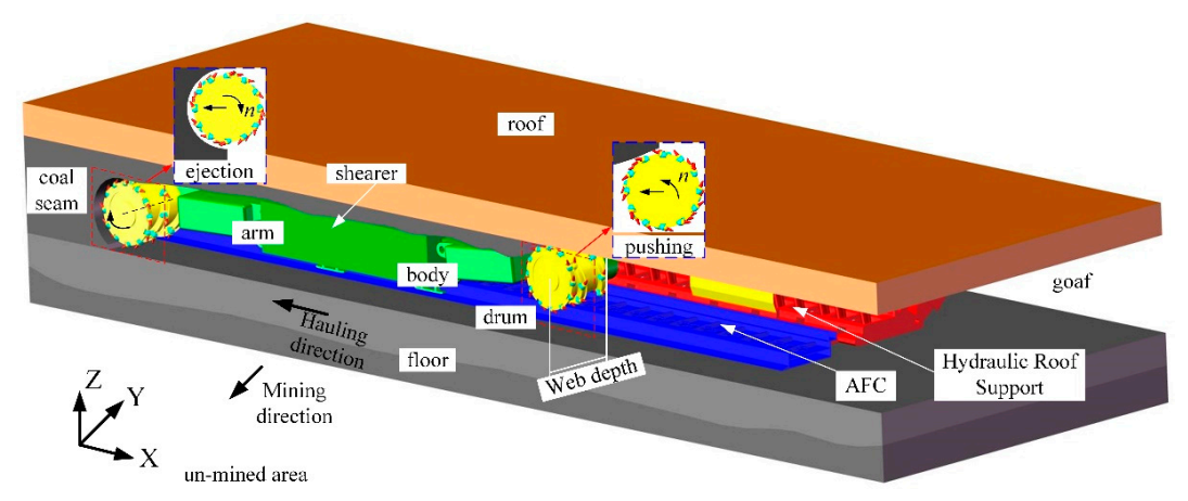
Figure 1. Schematic of shearer working in coal face.
Energies 14 00358 g001
Figure 2. The kinematic analysis of a single particle under the action of the vane.
Energies 14 00358 g002
Figure 3. The theory velocity of particle: (a) axial velocity Va; (b) tangential velocity Vt.
Energies 14 00358 g003
Figure 4. (a) Actual shearer drum; (b) The ranging arm with two-segment differential rotational speed drum (TDRSD). 1. Front drum; 2. Rear drum; 3. Drive gear of rear drum; 4. Drive gear of front drum; 5. Bearing; 6. Idler wheel; 7. Planetary gear train; 8. Motor gear; 9. Conical pick; 10. Single drum.
Energies 14 00358 g004
Figure 5. The schematic of the theoretical track of particle with coal ejection.
Energies 14 00358 g005
Figure 6. The diagram of the relationship between maximum web depth and helix angle.
Energies 14 00358 g006
Figure 7. The contact model of particles in discrete-element method (DEM).
Energies 14 00358 g007
Figure 8. The comparison of calibration results between experiment and DEM.
Energies 14 00358 g008
Figure 9. The simplified diagram of the model in DEM.
Energies 14 00358 g009
Figure 10. The diagram of the different statistical area.
Energies 14 00358 g010
Figure 11. The particles velocities in three-dimension: (a) velocity in X direction; (b) velocity in Y direction; (c) velocity in Z direction.
Energies 14 00358 g011
Figure 12. The distribution of P1 and P2 particles in different statistical areas: (a) statistical area 1; (b) statistical area 2; (c) statistical area 3; (d) statistical area 4.
Energies 14 00358 g012
Figure 13. The P1 value in area 1 and area 4 under the same nR: (a) area 1; (b) area 4.
Energies 14 00358 g013
Figure 14. The schematic under the condition of nF = 45 rpm, nR = 75 rpm.
Energies 14 00358 g014
Figure 15. The loading rate of different rotational speed matching between the front and rear drum.
Energies 14 00358 g015
Figure 16. The loading rate difference between the single drum and TDRSD with the same nR.
Energies 14 00358 g016
Figure 17. The velocity in three-direction of particles in the envelope zone under different helix angle matching. (a) X-direction; (b) Y-direction; (c) Z-direction.
Energies 14 00358 g017aEnergies 14 00358 g017b
Figure 18. The distribution of particles in P1 and P2 in different areas: (a) area 1; (b) area 2; (c) area 3; (d) area 4.
Energies 14 00358 g018
Figure 19. The loading rate of the different matching relationship of helix angle between front and rear drum.
Energies 14 00358 g019
Table 1. The material parameters in DEM.
ρ (kg/m3)σE (GPa) ημSμR
coal1.28 × 1030.284.25coal-coal0.500.800.10
steel7.85 × 1030.302.06 × 102coal-steel0.500.510.05
ρ is the density, kg/m3; σ is the Poisson’s ratio; E is Young’s modulus, GPa; η is the coefficient of restitution; μS is the coefficient of static friction; μR is the coefficient of rolling friction.
Table 2. The kinematic and geometric parameters.
n (rpm)Vq (m/s)J (m)Dv (m)Dc (m)H (m)αcp (°)N
Front drum[30:15:90]0.10.450.91.01.05242
Rear drum[37.5:7.5:90]0.10.400.91.01.05241
The rotational speed range of front drum is from 30 rpm to 90 rpm, and the increment is 15 rpm. Vq is the hauling speed, m/s; n is the rotational speed of drum, rpm; J is the web depth of drum, m; Dv is the diameter of screw vanes, m; Dc is the diameter of cutting picks, m; H is the height of coal face, m; αcp is the helix angle of screw vanes, °; N is the number of screw vanes.
Table 3. The geometric parameter of variable helix angle.
n (rpm)αcp (°)N
Front drum30[15:3:30]2
Rear drum60[15:3:30]1
Table 4. The difference in coal loading rate between single and TDRSD and particles’ value in P1 and P2.
Rotational Speed (rpm)The Difference in Loading Rate between Single and TDRSD (%)Loading Rate (%)
nFnRP1ΔP1P2ΔP2ΔP
60
(single drum)
20.27 36.05 56.32
306028.01+7.7437.03+0.98+8.7265.04
456025.18+4.9135.16−0.89+4.0260.34
75
(single drum)
16.47 33.52 49.99
307527.84+11.3735.98+2.46+13.8363.82
457522.66+6.1934.19+0.67+6.8656.85
607521.69+5.2235.10+1.58+6.8056.79
90
(single drum)
15.04 27.79 42.83
309022.96+7.9229.71+1.92+9.8452.67
459018.77+3.7332.83+5.04+8.7751.60
609016.63+1.5929.42+1.63+3.2246.05
ΔP was the difference between single and TDRSD, ΔP1 was the difference of P1 between single and TDRSD, ΔP2 was the difference of P2 between single and TDRSD.
Table 5. The statistical results of loading rate under different rotational speed matching.
Vq (m/s)nF (rpm)nR (rpm)αF (°)αR (°)Loading Rate (%)
2.430 (single drum)2446.41
3037.5242451.92
45242455.40
52.5242461.26
60242465.04
67.5242466.94
75242463.82
82.5242456.75
90242462.67
45 (single drum)2452.07
4552.5242457.47
60242460.34
67.5242458.93
75242456.85
82.5242455.32
90242451.60
60 (single drum)2456.32
6067.5242457.30
75242456.79
82.5242452.38
90242446.05
75 (single drum)2449.99
90 (single drum)2442.83
Table 6. The statistical results of loading rate under different helix angle matching.
Vq (m/s)nF (rpm)nR (rpm)αF (°)αR (°)Loading Rate (%)
2.460 (single drum)1545.27
3060151859.73
152162.34
152463.38
152766.24
153070.13
60 (single drum)1849.51
3060182163.26
182465.98
182769.92
183070.77
60 (single drum)2150.40
3060212463.60
212766.81
213070.17
60 (single drum)2452.07
2749.29
3048.33
Publisher’s Note: MDPI stays neutral with regard to jurisdictional claims in published maps and institutional affiliations.