Article

Feedback Linearization and Maximum Torque per Ampere Control Methods of Cup Rotor Permanent-Magnet Doubly Fed Machine

School of Electrical and Information Engineering, Tianjin University, No.92 Weijin Road, Tianjin 300072, China
*
Author to whom correspondence should be addressed.
Energies 2021, 14(19), 6402; https://doi.org/10.3390/en14196402
Submission received: 26 August 2021 / Revised: 2 October 2021 / Accepted: 4 October 2021 / Published: 7 October 2021

Abstract

:
This paper establishes the state-space model of the cup rotor permanent-magnet doubly fed machine in the synchronous reference frame. The feedback-linearization control method is used to realize the decoupling control of flux and torque. Then, the upper and lower load torque boundaries are solved. Furthermore, to minimize the stator current magnitude of the control machine under a certain torque, the maximum torque per ampere (MTPA) control is derived. Finally, simulation results demonstrate the good decoupling performance of the feedback-linearization control method and the correctness of the load torque boundaries. In addition, the effectiveness and robustness of the proposed control methods are also demonstrated.

1. Introduction

In order to alleviate the pressure of energy shortage and environmental pollution, a hybrid system is widely used [1]. Couplers are particularly important in the hybrid system. Coupling modes include power coupling, speed coupling, and torque coupling. The planetary gear mechanism used in the Prius series car is a speed coupler which can realize power coupling together with a permanent-magnet synchronous generator and a permanent-magnet synchronous machine [2]. According to the power-command value output by the energy management controller, the working point of the internal combustion engine can conduct torque-speed and two-dimensional optimization. In contrast to the above mechanical coupling scheme, the four-port electromechanical energy converter cascades two induction machines [3,4]. This pure electrical coupling scheme realizes the power coupling, but the existence of the brush and slip ring shortens the service life of the machine and increases the maintenance cost. The cup rotor permanent-magnet doubly fed machine studied in this paper has no brush and slip ring and is composed of a wound stator, a cup rotor, and a rotating permanent-magnet stator [5]. By adjusting the power-supply frequency of the stator windings, the speed of the permanent-magnet stator can be adjusted to optimize the working point of the internal combustion engine, so it can be used as a speed coupler for vehicle driving.
Up to now, there are few reports on the modeling and control methods of the cup rotor permanent-magnet doubly fed machine. In terms of a mathematical model, only the mathematical model of the cup rotor permanent-magnet doubly fed machine in the two-phase rotor reference frame has been established, and the open-loop operation characteristics are simulated based on this model [5]. The equivalent circuit of the cup rotor permanent-magnet doubly fed machine is given in [6]. In [7], the vector control based on the rotor magnetic-field orientation is designed for the cup rotor permanent-magnet doubly fed machine, but the decoupling control is not realized, and the simulation results are not given.
The cup rotor permanent-magnet doubly fed machine is similar to the brushless doubly fed machine (BDFM) in the modeling and control methods. So, this paper takes the BDFM as a pointcut for research. The mathematical model of the BDFM has experienced the transition from the multi-loop mathematical model to the double synchronous reference frame and then to the unified synchronous reference frame [8,9,10]. The model of the BDFM in the unified synchronous reference frame has many advantages, but so far, this model has not been given in the form of state space and is mostly used in the stator magnetic-field-orientation control methods. It needs to be modified as necessary for the content and control purposes of this paper.
The control methods of the BDFM include scalar control, vector control, and direct torque control. To get better control performance, vector control is a better option. Vector control can be divided into two kinds according to different mathematical models. One is the method based on the double synchronous reference frame model introduced in [9]. For the high-power machines, the method in [9] ignores the stator resistance of the power machine so the influence of the control machine on the stator magnetic-field of the power machine is ignored. The stator magnetic-field of the power machine is determined by the stator voltage of the power machine. Based on this, the rotor magnetic-field is decomposed into two parts which are excited by the stator magnetic-field of the power machine and the stator current of the control machine, respectively. Based on the control machine stator-current-excitation part, the stator current of the control machine is controlled by the same method as the asynchronous machine slip-frequency type vector control. At the same time, the machine torque is calculated based on the decomposition of the rotor magnetic-field, and the stator-current reference value of the control machine is determined to control the torque and rotor flux. Obviously, because the rotor magnetic field excited by the stator current of the control machine is only a component of the rotor magnetic field, it cannot really reflect the excitation of the machine’s magnetic-field and the saturation of the rotor magnetic circuit and make them effectively controlled. In addition, the decomposition of the rotor magnetic-field makes the control method complicated and the calculation amount increase significantly.
The other method is based on the unified synchronous reference frame model introduced in [11]. The unified reference frame model of the BDFM can be obtained by selecting one of the power machines or control machines and taking the conjugate transformation of the relevant variables. In [11], the vector sum of the rotor flux of the power machine and the control machine, that is, the total flux coupled by the rotor windings, is taken as the variable and referred to as the rotor flux. Because the pole pairs of the power machine and the control machine are different, the rotor flux mentioned above cannot reflect the excitation and the saturation of the magnetic circuit of the rotor. Therefore, this model is mainly used in the control method of the BDFM based on the stator magnetic-field orientation for the grid-connected power generation to realize the control of the reactive power and speed. Moreover, this control is only a simple feedback control in the synchronous reference frame, without a decoupling control characteristic. The control method given in [12] combines the above two control methods, but it does not directly control the flux, and it also requires a certain amount of calculation. In order to eliminate the influence of the machine parameters on the vector control system, the literature [13] adds an extended Kalman filter to the parameter identification on the basis of the vector control, which improves the robustness of the control system.
In addition, and also for the high-power BDFM, because the rotor impedance of the machine is much smaller than the inductive reactance, the asynchronous torque of the BDFM is very small and only the synchronous torque is considered; the output torque of the BDFM is proportional to the angle between the stator magnetic-field of the control machine and the stator magnetic-field of the power machine. Thus, the direct-torque-control method of the BDFM can be given. Obviously, due to the approximation in modeling, when the torque output is large and the speed is wide, there is a problem of loss of control, and the driving ability of the machine cannot be fully played [14]. In [15], the output capacity of the BDFM direct-torque-control system is improved by setting a flux-angle inner loop.
To improve the efficiency of the machine, the maximum torque per ampere (MTPA) control method has been proposed [16,17]. So far, there is little research on the MTPA control of the BDFM, and the MTPA control of the BDFM is more complex. In [18,19], for the BDFM an offline search method is adopted to realize the steady-state efficiency optimization. In particular, there is no MTPA control method for the machine studied in this paper.
The main purpose of this paper is to design control methods to maximize the performance of the cup rotor permanent-magnet doubly fed machine. The works conducted by the authors’ laboratory on the BDFM include the state-space model in the unified reference frame of the BDFM; the feedback linearization and slip-frequency type vector control method based on this model [20,21]; the improvement of direct torque control by setting the inner loop of the flux-angle [15]; and the maximum load capacity of the BDFM [22]. According to the research results of the BDFM and the research ideas of the authors’ laboratory, for the cup rotor permanent-magnet doubly fed machine, a new type of machine, this paper first establishes the state-space model in the unified synchronous reference frame. Based on this model, the feedback-linearization control method is designed to realize the decoupling control of the flux and torque, and the load capacity of this machine is solved. Furthermore, this paper studies the MTPA control method of this machine.
This paper is organized as follows: Section 2 establishes the state-space model of the cup rotor permanent-magnet doubly fed machine in the unified synchronous reference frame. Section 3 derives the feedback-linearization control method of the cup rotor permanent-magnet doubly fed machine. Section 4 solves the static load capacity of the cup rotor permanent-magnet doubly fed machine. Section 5 further deduces the MTPA control law. Section 6 is the simulation verification of the two control methods and the load torque boundaries. Section 7 is the summary of the whole paper.

2. Mathematical Model of Cup Rotor Permanent-Magnet Doubly Fed Machine

The cup rotor permanent-magnet doubly fed machine is composed of a rotating permanent-magnet stator, a cup rotor with inner and outer windings connected in a reverse phase sequence and a wound stator, as shown in Figure 1. The rotating permanent-magnet stator is connected to the internal combustion engine (ICE); the wound stator is connected to the inverter; and the cup rotor is used as the output shaft. Similar to the BDFM, the inner winding of the cup rotor and the rotating permanent-magnet stator constitute the power machine with pole pairs of p p , while the outer winding of the cup rotor and the wound stator constitute the control machine with pole pairs of p c .
From the reverse phase sequence connection relationship between the inner and outer windings of the cup rotor, it is easy to see that when the steady sinusoidal current flows through the rotor windings, the inside and outside magnetic fields of the rotor rotate in the opposite direction with an equal electric angular speed relative to the rotor, and the machine can output a stable torque. At this time, the cup rotor speed is
n r = p p n m + 60 f c p p + p c
When f c > 0 , the machine is in a super-synchronous operation state; when f c < 0 , the machine is in a sub-synchronous operation state; and when f c = 0 , the machine is in a synchronous operation state. So, the cup rotor speed can be adjusted by adjusting f c ; the cup rotor permanent-magnet doubly fed machine shows the characteristics of the synchronous machine, and when rotor losses are ignored, the torques of the control machine and the power machine are in the same direction and proportional to their pole pairs. If this machine is used in hybrid electric vehicles, when the ICE shaft is locked, that is, n m = 0 , the vehicle works in pure electric mode; when f c = 0 , the vehicle works in ICE independent drive mode; otherwise, the vehicle works in hybrid drive mode. In the above three modes, the output torque of the machine can be controlled by controlling the stator current of the control machine. In particular, in the hybrid mode, except to respond to the output torque reference value, the ICE speed optimization can be realized by controlling f c to reduce fuel consumption (speed coupling).
The relationships between the reference frames are shown in Figure 2, and the transformations between the reference frames are in accordance with the principle of equal power transformation, and the counterclockwise rotation is positive.
The control machine of the cup rotor permanent-magnet doubly fed machine is an asynchronous machine, and the power machine can be regarded as a surface-mounted permanent-magnet synchronous machine with stator rotation. Obviously, there is only electrical coupling between the two rotor windings but no coupling between the magnetic fields. The stator and rotor voltage models of the control machine in the rotor reference frame are as follows
{ u cs d q = ( r cs + j p c ω r l cs ) i cs d q + j p c ω r l cm i cr d q + l cs i ˙ cs d q + l cm i ˙ cr d q u cr d q = r cr i cr d q + l cm i ˙ cs d q + l cr i ˙ cr d q
In this paper, all vectors are expressed in the complex form of their projection values on a two-phase reference frame; for example, u cs d q = u cs d + j u cs q , no more details below.
The stator and rotor fluxes of the control machine are
{ ψ cs d q = l cs i cs d q + l cm i cr d q ψ cr d q = l cm i cs d q + l cr i cr d q
The rotor voltage model of the power machine in the rotor reference frame is
u pr d q = r pr i pr d q + l pr i ˙ pr d q + j λ ˙ fdq ψ f d q
and the expression for λ fdq is
λ fdq = 0 t ( p p ω m p p ω r ) d t
The rotor flux and the permanent-magnet flux of the power machine are
{ ψ pr d q = l pr i pr d q + ψ f d q ψ f d q = ψ f ( cos λ fdq + jsin λ fdq )
The electromagnetic torque of the cup rotor permanent-magnet doubly fed machine is
T e = p c l cm Im { i ¯ cr d q i cs d q } + p p Im { ψ f d q i ¯ pr d q }
The three-phase voltage and current relationship of the rotor under the reverse phase sequence connection is shown in Figure 3. After 3/2 transformation, the rotor voltage and the current relationships of the power machine and the control machine in the rotor reference frame are as follows
{ u cr d q = u ¯ pr d q i cr d q = i ¯ pr d q
Next, taking the negative conjugate operation on both sides of Equation (4), substituting Equation (8) into it, and redefining the variables of the power machine,
{ i r d q = i pr d q = i ¯ pr d q = i cr d q ψ pr d q = ψ ¯ pr d q ψ f d q = ψ ¯ f d q
The mathematical model of the cup rotor permanent-magnet doubly fed machine in the rotor reference frame can be obtained as follows
{ u cs d q = ( r cs + j p c ω r l cs ) i cs d q + j p c ω r l cm i r d q + l cs i ˙ cs d q + l cm i ˙ r d q 0 = r r i r d q + l r i ˙ r d q + l cm i ˙ cs d q j λ ˙ fdq ψ f d q
where r r = r cr + r pr , l r = l cr + l pr .
The reasons for the negative conjugation are as follows: as shown in Figure 4, when the machine is running stably, relative to the rotor reference frame, the flux of the control machine and the flux of the power machine rotate in opposite directions and have equal electrical speed; that is, ω cr = ω pr . Because the voltage and current of the power machine and the control machine are AC variables in the rotor reference frame, this increases the difficulty of control. If the control machine variables are taken as the benchmark and the power machine variables are performed as a negative conjugate operation, then all the variables rotate in the same direction relative to the rotor reference frame, and all the variables in the synchronous reference frame of the control machine are DC values, which is convenient for the design of the control methods.
So, Equation (10) is called the unified reference frame model. Next, Equation (10) is rotated to the synchronous reference frame of the control machine, and the rotation transformation rule is
x d q = e j λ c x m t
Then, the state-space model in the synchronous reference frame can be obtained.
x ˙ m t = A m t x m t + B m t u m t
where A m t = [ l r ( r cs + j p c ω r l cs ) K j λ ˙ c l cm ( r r j p c ω r l r ) K l cm ( r cs + j p c ω r l cs ) K l cs r r + j p c ω r l cm 2 K j λ ˙ c ] , B m t = [ l r K j l cm λ ˙ fdq K l cm K j l cs λ ˙ fdq K ] , x m t = [ i cs m t i r m t ] , u m t = [ u cs m t ψ f m t ] , K = l cs l r l cm 2 , i cs m t and i r m t are the state variables, u cs m t and ψ f m t are the input variables.
The electromagnetic torque in the synchronous reference frame is expressed as
T e = p c l cm Im { i ¯ r m t i cs m t } + p p Im { ψ ¯ f m t i r m t }
Finally, the motion equation of the cup rotor permanent-magnet doubly fed machine is
T e T L = J d ω r d t

3. Feedback Linearization Control of Cup Rotor Permanent-Magnet Doubly Fed Machine

In order to fully play the driving performance of the cup rotor permanent-magnet doubly fed machine, its input and output feedback linearization control is considered here. In addition, machine control systems generally have fast-responding current loops; this is equivalent to the control machine supplied by the current source. In order to obtain the state-space description of the machine when the control machine is supplied by the current source (this means that the stator current of the control machine will be the input variable, rather than the stator voltage of the control machine), new state variables need to be redefined to remove the influence of the stator voltage of the control machine on the system state variables. Through the observation of the first column of the B m t in the Equation (12), it is easy to see that the above purposes can be achieved by defining the following new state variable
ψ c m t = l r i r m t + l cm i cs m t
Note that since the permeability of the permanent magnet in the magnetic circuit of the power machine is close to the air and the air gap is much larger than that of the control machine, l pr is very small so there is l r l cr . The newly defined state variable in Equation (15) is close to the rotor flux of the control machine so it is called the rotor flux of the control machine. The rotor flux of the control machine defined by Equation (15) is different from the rotor flux defined by the vector sum of the rotor flux of the power machine and the control machine with different pole pairs in [23,24]. The amplitude of the rotor flux is usually small and cannot reflect the saturation of the rotor magnetic circuit. This also indicates that the rotor flux of the power machine and the control machine with different pole pairs are two vectors with approximately equal size and opposite directions. Based on the above facts, the rotor flux of the control machine defined in Equation (15) is selected as the state variable in this paper so that the saturation of the magnetic circuit of the rotor of the machine can be more effectively controlled.
According to the reasons given above, the newly defined state variable ψ c m t is substituted into Equation (12) to replace the original state variables i cs m t , i r m t . In addition, under the current source, the first line of the stator voltage equation in Equation (12) is removed. The mathematical model of the cup rotor permanent-magnet doubly fed machine is obtained.
ψ ˙ c m t = r r l r ψ c m t + r r l cm l r i cs m t + j λ ˙ fdq ψ f m t j λ ˙ c ψ c m t
Equation (16) is a two-order model, and the electromagnetic torque of the machine expressed by the new variable is
T e = p c l cm l r Im { ψ ¯ c m t i cs m t } + p p l r Im { ψ ¯ f m t ψ c m t } p p l cm l r Im { ψ ¯ f m t i cs m t }
Next, the rotor magnetic-field of the control machine is oriented; that is, ψ c m t = ψ c + j 0 so Equations (16) and (17) can be written as
ψ ˙ c = r r l cm l r i cs m r r l r ψ c λ ˙ fdq ψ f t
0 = r r l cm l r i cs t + λ ˙ fdq ψ f m λ ˙ c ψ c
T e = i cs t ( p c l cm l r ψ c p p l cm l r ψ f m ) p p l r ψ f t ψ c + p p l cm l r ψ f t i cs m
The rotor flux of the control machine and the electromagnetic torque are selected as the output variables, and their expressions can be divided into the linear part, the state-dependent nonlinear part, and the input-dependent part, as follows
[ ψ ˙ c T e ] = [ r r l r ψ c 0 ] + f ( x ) + D ( x ) [ i cs m i cs t ]
where f ( x ) = [ λ ˙ fdq ψ f t p p l r ψ f t ψ c ] , D ( x ) = [ r r l cm l r 0 p p l cm l r ψ f t p c l cm l r ψ c p p l cm l r ψ f m ] .
Obviously, the relationship between the torque and the stator current of the control machine is nonlinear, and the rotor flux of the control machine and torque are coupled. According to Equation (21), the input-output feedback linearized control method is designed to realize the decoupling control of the flux and torque.
When D ( x ) is nonsingular, the input-output feedback linearization can be performed by the following control law
[ i cs m i cs t ] = D 1 ( x ) [ f ( x ) + v ]
where v = [ v 1 v 2 ] T is a new input variable, and Equation (21) can be written as
[ ψ ˙ c T e ] = [ r r l r ψ c 0 ] + [ v 1 v 2 ]
From Equation (23), it can be seen that the rotor flux of the control machine from the input v 1 is an inertial link, and the electromagnetic torque is proportional to the input v 2 . The rotor flux and the torque are completely decoupled. The reference values of the input variables are
[ v 1 * v 2 * ] = [ r r l r ψ c * T e * ]
According to Equation (22), the feedback linearization control can be carried out on the premise that D ( x ) is nonsingular; that is,
p c ψ c p p ψ f m 0
In the electromagnetic torque expression, p c ψ c p p ψ f m appears in the form of the coefficient of i cs t . This coefficient is not expected to cross zero in the control process, otherwise the torque would be out of control. Obviously, when the following equation is satisfied, the requirement of Equation (25) can be satisfied.
ψ c > p p p c ψ f
In the above statements, the rotor flux of the control machine and the torque are taken as the output variables. It can be known from Equations (18) and (20) that the input variable i cs m appears after the first derivative of the rotor flux; so, its relative order is 1. The electromagnetic torque expression itself contains inputs i cs m t ; so, its relative order is 0. Therefore, the relative order of the system outputs to the inputs is 1, which is consistent with the order of the mathematical model of the machine after magnetic-field orientation (Equation (18)). Therefore, this system has no zero dynamic after the feedback linearization.

4. Static Load Capacity of Cup Rotor Permanent-Magnet Doubly Fed Machine

This section discusses the static load capacity of the cup rotor permanent-magnet doubly fed machine. When the machine have sinusoidal steady-state solutions, all the variables in the synchronous reference frame are DC values so Equation (18) can be written as
0 = r r l cm l r i cs m r r l r ψ c λ ˙ fdq ψ f t
Then, Equations (19) and (27) are substituted into Equation (20) to get the electromagnetic torque expression; that is,
T e = λ ˙ c r r p c ψ c 2 + λ ˙ fdq r r p p ψ f 2 λ ˙ fdq r r p c ψ c ψ f m λ ˙ c r r p p ψ c ψ f m
It can be seen from Equation (28) that the electromagnetic torque is limited under certain rotor flux, speed, and machine parameters. The load torque boundaries will be solved.
When the machine is running stably, T L = T e , λ ˙ c = λ ˙ fdq = 2 π p p ( n r n m ) / 60 ; so, Equation (28) can be written as
T L = 2 π p p ( n r n m ) 60 r r ( p c ψ c 2 p p ψ f 2 + ( p c p p ) ψ c ψ f m )
It can be seen from Equation (29) that under the certain speed and machine parameters, when ψ f m = ψ f or ψ f m = ψ f , the upper and lower load torque boundaries of the machine with sinusoidal steady-state solution can be obtained. According to the parameters of the cup rotor permanent-magnet doubly fed machine in Table 1, the load torque is converted into per-unit value based on the rated torque; that is, T Lb = T L / T N and the numerical calculation results of the load capacity are shown in Figure 5 and Table 2.
It can be seen from Equation (29) that the upper and lower load torque boundaries are inversely proportional to the rotor resistance. In addition, when the supply voltage and frequency are constant, the flux amplitude is constant, and the inductive reactance and impedance decrease proportionally with the increase in the capacity of the machine; so, the per-unit values of the upper and lower load torque boundaries are independent of the capacity of the machine. Therefore, the load capacity of the machine can be improved by reducing the rotor resistance.
Furthermore, the upper and lower load torque boundaries are affected by the machine speed. According to Equation (29), when the rotor flux of the control machine is constant, the width of the load torque interval decreases linearly, and the load torque capacity becomes weak with the decrease in the speed difference n r n m , as shown in Figure 6a. In addition, as shown in Figure 6b, when the machine speed is constant, the width of the load torque interval is positively correlated with the rotor flux of the control machine. However, when the rotor flux of the control machine increases, the positive load capacity of the machine becomes weak. Therefore, the rotor flux of the control machine can be appropriately reduced at high speed.

5. MTPA Control of Cup Rotor Permanent-Magnet Doubly Fed Machine

In order to minimize the stator current amplitude of the control machine when the electromagnetic torque is fixed, Lagrange’s theorem is used to find out the extremum relation. The auxiliary function introduced is
F = ( i cs m ) 2 + ( i cs t ) 2 + λ ( T e i cs t ( p c l cm l r ψ c p p l cm l r ψ f m ) + p p l r ψ f t ψ c p p l cm l r ψ f t i cs m )
Next, the partial derivatives are taken with respect to i cs m , i cs t , and λ and made equal to 0.
{ F i cs m = i cs m ( ( i cs m ) 2 + ( i cs t ) 2 ) 1 2 λ ( p p l cm l r ψ f t ) = 0 F i cs t = i cs t ( ( i cs m ) 2 + ( i cs t ) 2 ) 1 2 λ ( p c l cm l r ψ c p p l cm l r ψ f m ) = 0 F λ = T e i cs t ( p c l cm l r ψ c p p l cm l r ψ f m ) + p p l r ψ f t ψ c p p l cm l r ψ f t i cs m = 0
From the first two lines of Equation (31), the ratio of i cs m to i cs t can be obtained.
i cs m i cs t = p p ψ f t p c ψ c p p ψ f m
The third line in Equation (31) can be written as
i cs t = T e + p p l r ψ f t ψ c p p l cm l r ψ f t i cs m ( p c l cm l r ψ c p p l cm l r ψ f m )
In addition, Equation (18) can be written as
i cs m = l r r r l cm ( ψ ˙ c + r r l r ψ c + λ ˙ fdq ψ f t )
From Equations (33) and (34), the ratio of i cs m to i cs t can also be obtained as follows
i cs m i cs t = ( l r ψ ˙ c + r r ψ c + l r λ ˙ fdq ψ f t ) ( p c ψ c p p ψ f m ) l r ( r r T e p p ψ f t ψ ˙ c p p λ ˙ fdq ψ f t 2 )
So, by substituting Equation (32) into Equation (35), the relationship can be obtained as follows
( l r ψ ˙ c + r r ψ c + l r λ ˙ fdq ψ f t ) ( p c ψ c p p ψ f m ) l r ( r r T e p p ψ f t ψ ˙ c p p λ ˙ fdq ( ψ f t ) 2 ) = p p ψ f t p c ψ c p p ψ f m
The speed loop and the MTPA control are the outer loops. They generate the reference values of the torque of the feedback linearization and the rotor flux of the control machine. The changes in the torque and rotor flux of the control machine are ignored and replaced by their reference values. Equation (36) can be written as
( r r ψ c * + l r λ ˙ fdq ψ f t ) ( p c ψ c * p p ψ f m ) l r ( r r T e * p p λ ˙ fdq ( ψ f t ) 2 ) = p p ψ f t p c ψ c * p p ψ f m
To solve the rotor flux reference value of the control machine under a different torque, Equation (37) can be converted into the following form
ψ c * = p p ψ f t ( r r l r T e * l r p p λ ˙ fdq ( ψ f t ) 2 ) r r ( p c ψ c * p p ψ f m ) 2 l r λ ˙ fdq ψ f t r r
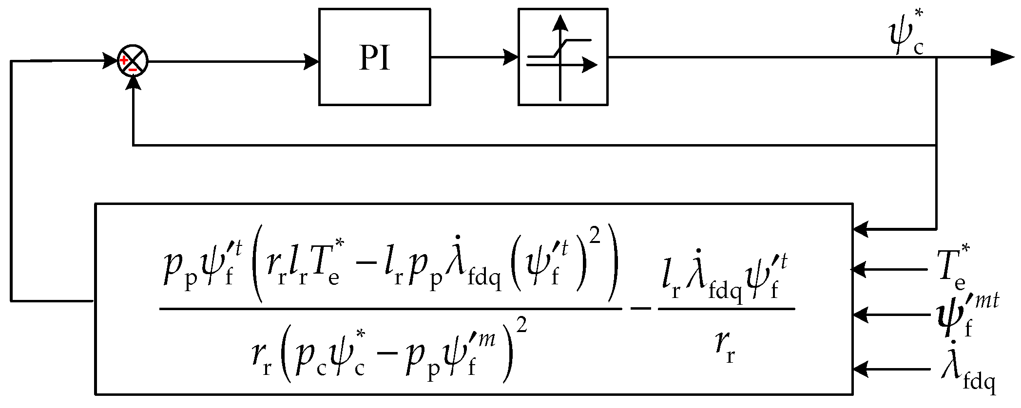
Accordingly, the following feedback regulation system (Figure 7) is constituted. Obviously, when the value of ψ c * converges to a constant, the solution of the above Equation (37) is obtained.
So far, the control system block diagram of the slip-frequency type realization of the feedback linearization and the MTPA control of the cup rotor permanent-magnet doubly fed machine is shown in Figure 8. The output of the speed loop is the torque reference value, and the rotor flux reference value of the control machine is obtained by the MTPA control. The synchronization angle used for the rotation transformation is obtained by integrating the sum of the angular speed ω r of the machine and the slip angular speed λ ˙ c obtained by Equation (19), and the rotor flux and stator current of the control machine in Equation (19) are replaced by the reference values; that is,
λ ˙ c = r r l cm l r ψ c * i cs t * + λ ˙ fdq ψ c * ψ f m
Then, the reference values of the rotor flux of the control machine and the torque are the inputs of the feedback linearization control law to get the stator-current reference values of the control machine.
Finally, in order to show the change of the rotor flux of the control machine under the different speed and torque, Equations (29) and (37) and ( ψ f m ) 2 + ( ψ f t ) 2 = ( ψ f ) 2 are combined to solve the MTPA control law offline. Then, under the machine parameters in Table 1, the rotor-flux reference value is obtained under different speeds and torques and plotted as a three-dimensional surface, and the torque is converted into per-unit value based on the rated torque; that is, T eb = T e / T N , as shown in Figure 9. In addition, for the convenience of comparison and analysis, the above three-dimensional surface is converted into two dimensions, as shown in Figure 10. When the speed of the machine is constant, the rotor-flux reference value of the control machine decreases with the increase in the torque. Similarly, when the torque is constant, the rotor-flux reference value of the control machine also decreases with the increase in the speed.

6. Simulation Experiments

6.1. Verification of Feedback Linearization Control Performance and Load Torque Boundaries

The machine parameters in the simulation experiments are also shown in Table 1. Firstly, in order to verify the performance of feedback linearization control and facilitate comparative analysis with the following simulation, the MTPA control is not adopted in this section; that is, let ψ c * = constant in Figure 8. In Figure 8, the proportional coefficient of the current-loop PI controller is set as 1000, and the integral coefficient is set as 400. The PI controller with anti-windup is adopted for the speed-loop controller, as shown in Figure 11, where K p = 80 , K i = 3.5 , K a = 50 .
As shown in Figure 12, the rotor-flux reference value of the control machine is 1.0 Wb in 0–4.5 s, 0.9 Wb in 4.5–5.5 s, and the speed reference value is 1500 r / min . The load torque changes from 0 to 0.5 T N at 1.5 s, and then the load torque changes to T N at 3 s. At each loading, the machine speed returns to the steady state after a slight fluctuation, which shows that this control method has a certain adjusting ability. In addition, the changes of rotor flux of the control machine and torque have no influence on each other, realizing the decoupling control.
As shown in Figure 13, the machine-speed reference value is 500 r / min in 0–1.5 s, 750 r / min in 1.5–3 s, and 1500 r / min in 3–4.5 s. The rotor-flux reference value of the control machine is 1.0 Wb, and the machine load torque is rated torque T N . It can be seen from the simulation results that the machine speed can follow the changes of reference value without error under the rated torque. This shows that the tracking performance of the control system is good.
When ψ c * = constant , it is easy to verify the load torque boundaries. In this section, the upper boundary of the load torque is taken as an example. As shown in Figure 14, the speed reference value is always 1500 r / min , and the rotor-flux reference value is 0.9 Wb before 2.5 s. In addition, the load torque is rated torque T N before 0.75 s. When the load torque changes to 2 T N at 0.75 s, the machine still runs stably. However, when the load torque changes to 2.55 T N at 1.5 s, the stator current of the control machine starts to oscillate, and the machine runs unstably. This is because, according to Table 2, 2.55 T N exceeds the upper boundary of the load torque. However, when the rotor-flux reference value is reduced to 0.8 Wb at 2.5 s, the machine can run stably again because the load torque is within the boundaries of the load torque at this time. Then, the load torque continues to be increased to 3.15 T N at 3 s, and it exceeds the upper boundary of the load torque so the stator current of the control machine starts to oscillate again. The above content shows the correctness of the load torque boundaries.

6.2. Verification of the Effectiveness of MTPA Control

Secondly, the effectiveness of the MTPA control is verified by simulation. In addition, the MTPA control method in this section is shown in Figure 8. The proportional coefficient of the PI controller in the closed-loop feedback system of Figure 7, which is used to solve the reference value of the rotor flux, is set as 10, and the integral coefficient is set as 2. The simulation results of the MTPA control and the ψ c * = constant are compared and analyzed, respectively, under the two simulation conditions of constant-speed torque increase (as shown in Figure 12) and constant-torque speed increase (as shown in Figure 13). By comparing the 0.5–4.5 s period in Figure 12 with Figure 15, it can be seen that the rotor flux of the control machine decreases with the increase in torque under the MTPA control, which is consistent with Figure 10a. The stator-current amplitude of the control machine is also smaller than that under the ψ c * = constant control. As the torque increases, the excitation current i cs m becomes negative and the torque current i cs t increases.
Similarly, by comparing Figure 13 and Figure 16, it can be seen that in the constant-torque acceleration process, the rotor flux of the control machine is also gradually decreasing, which is consistent with Figure 10b. The stator-current amplitude of the control machine is basically unchanged around 4.5 A, which is far less than the stator-current amplitude under the ψ c * = constant control. In conclusion, the effectiveness of the MTPA control is verified.

6.3. Verification of the Robustness of MTPA Control

Finally, the robustness of the MTPA control is verified. In order to compare with Figure 15 and Figure 16, the parameters in the control algorithm have an error of 20%; that is, r r reduces by 20% and l cs , l cm , l r increase by 20%. Other simulation conditions are the same as in Figure 15 and Figure 16.
As shown in Figure 17 and Figure 18, the rotor-flux reference value obtained by the MTPA control law is different with or without the parameter error, which leads the stator-current amplitude of the control machine to slightly increase. In addition, due to the parameter error, the actual rotor flux of the control machine is in error with the expected value. Even if there is a parameter deviation, the system can still work stably. The smaller the parameter deviation in the control algorithm, the more the accuracy of the controlled variable and the dynamic control effect tend to be in the ideal state without parameter deviation. This system shows stability robustness and performance robustness in parameter deviation.

7. Conclusions

In this paper, the model, control methods, and driving characteristics of the cup rotor permanent-magnet doubly fed machine are discussed. A potential application of this machine is the power-coupling system of hybrid electric vehicles. While responding to the pedal-torque reference value, according to the output speed of the machine, the ICE speed can be optimized by adjusting the power-supply frequency of the stator of the control machine to improve its efficiency and reduce fuel consumption. The contribution of this paper is that the input-output feedback-linearization control method and the MTPA control method are given by establishing the unified synchronous reference frame state-space model of the cup rotor permanent-magnet doubly fed machine; the analysis results of the output torque capacity of this machine are given. Among them, the input-output feedback linearization control forms the inner control loop of the rotor flux of the control machine and the torque, which can realize the decoupling control of the rotor flux of the control machine and the torque. The speed and the MTPA of the outer control loop can effectively reduce the amplitude of the stator current of the control machine and improve the power factor and system efficiency. The analyses of the driving characteristics of the cup rotor permanent-magnet doubly fed machine show that the maximum-output positive torque and the maximum-output negative torque interval of this machine is inversely proportional to the rotor resistance; proportional to the amplitude of the rotor flux of the control machine; and proportional to the speed difference between the cup rotor and the permanent-magnet stator. The simulation results show the effectiveness of the proposed control methods and the robustness of the system stability and the control performance when the parameters of the controller have errors. These results are of great significance to the system design of related applications and the machine design.

Author Contributions

Conceptualization, C.X.; methodology, C.X. and J.S.; software, J.S.; validation, C.X. and J.S.; formal analysis, C.X.; investigation, C.X.; resources, C.X.; data curation, C.X; writing—original draft preparation, C.X. and J.S.; writing—review and editing, C.X. and J.S.; visualization, J.S.; supervision, C.X.; project administration, C.X.; funding acquisition, C.X. All authors have read and agreed to the published version of the manuscript.

Funding

This research received no external funding.

Institutional Review Board Statement

Not applicable.

Informed Consent Statement

Not applicable.

Data Availability Statement

Not applicable.

Conflicts of Interest

The authors declare no conflict of interest.

Nomenclature

n r , n m , ω r mechanical speeds of cup rotor and permanent-magnet stator, and mechanical angular speed of cup rotor
f c frequency of the inverter
θ r , λ c , λ fdq rotor angle, slip angle and rotation angle of the N pole axis of permanent-magnet relative to d axis of the cup rotor
ppole pairs number
u ( u ) vector form (scalar form) of voltage
i ( i ) vector form (scalar form) of current
ψ ( ψ ) vector form (scalar form) of flux
r resistance
l inductance
l m mutual inductance
T e , T L , T N electromagnetic torque, load torque and rated torque
J rotational inertia
Imimaginary part
junit imaginary
λ lagrangian multiplier
P N rated power
Superscripts
ABCstatic stator three-phase reference frame
α β static stator two-phase reference frame
abcrotor three-phase reference frame
dqrotor reference frame
mtsynchronous reference frame
conjugate operation
.taking the derivative with respect to time
*reference value
Subscripts
ppower machine
ccontrol machine
sStator
rrotor
fpermanent magnet
bper-unit value

References

  1. Chau, K.T.; Chan, C.C.; Liu, C.H. Overview of permanent magnet brushless drives for electric and hybrid electric vehicles. IEEE Trans. Ind. Electron. 2008, 55, 2246–2257. [Google Scholar] [CrossRef] [Green Version]
  2. Cheng, Y.; Trigui, R.; Espanet, C.; Bouscayrol, A.; Cui, S.M. Specifications and design of a pm electric variable transmission for Toyota Prius II. IEEE Trans. Veh. Technol. 2011, 60, 4106–4114. [Google Scholar] [CrossRef]
  3. Hoeijmakers, M.J.; Ferreira, J.A. The electrical variable transmission. In Proceedings of the Conference Record of the 2004 IEEE Industry Applications Conference, Seattle, WA, USA, 3–7 October 2004; pp. 2770–2777. [Google Scholar]
  4. Cui, S.M.; Cheng, Y.; Chen, Q.Q. An advanced electrical variable transmission for automobiles. Trans. China Electrotech. Soc. 2006, 21, 111–116. [Google Scholar]
  5. Li, L.B.; Chen, P.; Shi, G.K.; Wang, H.J. Modeling and simulation of double-rotor motor applied to the system of hybrid electric vehicle. Electr. Mach. Control 2008, 12, 403–408. [Google Scholar]
  6. Ju, X.W.; Cheng, Y.; Zhao, T.X.; Cui, S.M. Torque characteristic analysis of a novel brushless dual rotor machine for hybrid electric vehicles. In Proceedings of the 22nd International Conference on Electrical Machines and Systems (ICEMS), Harbin, China, 11–14 August 2019; pp. 4365–4370. [Google Scholar]
  7. Xu, E.Z. Study on Hybrid Power System with Permanent Magnet Brushless Double Rotor Motor; Hebei University of Technology: Tianjin, China, 2011. [Google Scholar]
  8. Roberts, P.C.; McMahon, R.A.; Tavner, P.J.; Maciejowski, J.M.; Flack, T.J. Equivalent circuit for the brushless doubly fed machine (BDFM) including parameter estimation and experimental verification. IEE Proc.-Electr. Power Appl. 2005, 152, 933–942. [Google Scholar] [CrossRef] [Green Version]
  9. Zhou, D.S.; Spee, R. Synchronous frame model and decoupled control development for doubly-fed machines. In Proceedings of the 1994 Power Electronics Specialist Conference-PESC’94, Taipei, Taiwan, 20–25 June 1994; pp. 1229–1236. [Google Scholar]
  10. Poza, J.; Oyarbide, E.; Roye, D.; Rodriguez, M. Unified reference frame dq model of the brushless doubly fed machine. IEE Proc. Electr. Power Appl. 2006, 153, 726–734. [Google Scholar] [CrossRef]
  11. Shao, S.Y.; Abdi, E.; Barati, F.; McMahon, R. Stator-flux-oriented vector control for brushless doubly fed induction generator. IEEE Trans. Ind. Electron. 2009, 56, 4220–4228. [Google Scholar] [CrossRef]
  12. Han, P.; Cheng, M. Single-electrical-port control of cascaded doubly fed induction machine for EV/HEV applications. IEEE Trans. Power Electron. 2017, 32, 7233–7243. [Google Scholar] [CrossRef]
  13. Omar, S.; Hammou, D.; Krim, Y.; Mohamed, M. Application of the extended KALMAN filter to the parameters estimation in the vector control of the BDFIG. In Proceedings of the 4th IEEE International Conference on Smart Energy Grid Engineering (SEGE), Oshawa, ON, Canada, 21–24 August 2016; pp. 208–214. [Google Scholar]
  14. Sarasola, I.; Poza, J.; Rodríguez, M.Á.; Abad, G. Direct torque control design and experimental evaluation for the brushless doubly fed machine. Energy Convers. Manag. 2011, 2, 1226–1234. [Google Scholar] [CrossRef]
  15. Xia, C.Y.; Hou, X.X.; Chen, F. Flux-angle-difference feedback control for the brushless doubly fed machine. Energies 2017, 10, 1840. [Google Scholar]
  16. Hesar, H.M.; Zarchi, H.A.; Khoshhava, M.A. Online maximum torque per ampere control for induction motor drives considering iron loss using input–output feedback linearization. IET Electric. Power Appl. 2019, 13, 2113–2120. [Google Scholar] [CrossRef]
  17. Shinohara, A.; Inoue, Y.; Morimoto, S.; Sanada, M. Direct calculation method of reference flux linkage for maximum torque per ampere control in DTC-based IPMSM drives. IEEE Transaction. Power Electron. 2017, 32, 2114–2122. [Google Scholar] [CrossRef]
  18. Gorti, B.V.; Alexander, G.C.; Spee, R.; Wallace, A.K. Microcontroller based efficiency maximization for a brushless doubly-fed machine pump drive. In Proceedings of the IEEE/IAS International Conference on Industrial Automation and Control, Hyderabad, India, 5–7 January 1995; pp. 377–381. [Google Scholar]
  19. Mosaddegh, H.; Zarchi, H.A.; Markadeh, G.A. Stator flux oriented control of brushless doubly fed induction motor drives based on maximum torque per total ampere strategy. In Proceedings of the 2019 10th International Power Electronics, Drive Systems and Technologies Conference (PEDSTC), Shiraz, Iran, 12–14 February 2019; pp. 84–89. [Google Scholar]
  20. Xia, C.Y.; Guo, H.Y. Feedback linearization control approach for brushless doubly-fed machine. Int. J. Precis. Eng. Manuf. 2015, 8, 1699–1709. [Google Scholar] [CrossRef]
  21. Xia, C.Y.; Yu, J.L.; Tian, C.Y.; Hou, X.X. Slip frequency type vector control for brushless doubly-fed machine. Control. Decis. 2019, 34, 649–654. [Google Scholar]
  22. Xia, C.Y.; Hou, X.X. Study on the static load capacity and synthetic vector direct torque control of brushless doubly fed machines. Energies 2016, 9, 966. [Google Scholar] [CrossRef] [Green Version]
  23. Shao, S.Y.; Long, T.; Abdi, E.; McMahon, R. Dynamic control of the brushless doubly fed induction generator under unbalanced operation. IEEE Trans. Ind. Electron. 2013, 60, 2465–2476. [Google Scholar] [CrossRef]
  24. Wei, X.C.; Cheng, M.; Wang, W.; Han, P.; Luo, R.S. Direct voltage control of dual-stator brushless doubly fed induction generator for stand-alone wind energy conversion systems. IEEE Trans. Magn. 2016, 52, 1–4. [Google Scholar] [CrossRef]
Figure 1. Structure diagram of cup rotor permanent-magnet doubly fed machine.
Energies 14 06402 g001
Figure 2. The relationship between the reference frames. (a) The relationship between the static stator three-phase reference frame and the static stator two-phase reference frame; (b) the relationship between the rotor three-phase reference frame and the rotor dq reference frame; (c) the relationship between the rotor dq reference frame and the synchronous mt reference frame.
Energies 14 06402 g002
Figure 3. The structure of the rotor winding.
Energies 14 06402 g003
Figure 4. The relationship between the variables after the negative conjugate operation of the power machine variables.
Energies 14 06402 g004
Figure 5. The upper and lower boundaries of load torque.
Energies 14 06402 g005
Figure 6. Influence of the speed and rotor flux of the control machine on the upper and lower load torque boundaries. (a) Influence of the speed on the upper and lower load torque boundaries; (b) influence of the rotor flux of the control machine on the upper and lower load torque boundaries.
Energies 14 06402 g006
Figure 7. Block diagram of closed-loop feedback solution for Equation (37).
Energies 14 06402 g007
Figure 8. Control block diagram of cup rotor permanent-magnet doubly fed machine.
Energies 14 06402 g008
Figure 9. Reference value of the control machine’s rotor flux at different speeds and torques.
Energies 14 06402 g009
Figure 10. Specific numerical calculation results of MTPA control. (a) The change of the rotor flux with torque at a certain speed; (b) the change of the rotor flux with speed at a certain torque.
Energies 14 06402 g010
Figure 11. PI controller with anti-windup in speed loop.
Energies 14 06402 g011
Figure 12. Simulation results of ψ c * = constant control when torque changes.
Energies 14 06402 g012
Figure 13. Simulation results of ψ c * = constant control when speed changes.
Energies 14 06402 g013
Figure 14. Simulation verification of the upper boundary of load torque.
Energies 14 06402 g014
Figure 15. Simulation results of MTPA control when torque changes.
Energies 14 06402 g015
Figure 16. Simulation results of MTPA control when speed changes.
Energies 14 06402 g016
Figure 17. Simulation results of robustness verification of MTPA control when the torque changes.
Energies 14 06402 g017
Figure 18. Simulation results of robustness verification of MTPA control when speed changes.
Energies 14 06402 g018
Table 1. Parameters of cup rotor permanent-magnet doubly fed machine.
ParameterValueParameterValue
P N /kW4 l cm /H0.12
T N / N · m 25 ψ f /Wb1.2
r cs / Ω 1.22 n m / ( r / min ) 3000
r cr , r pr / Ω 1.5/1.5 p c 3
l cs /H0.123 p p 1
l cr , l pr /H0.123/0.0025 J / ( kg · m 2 ) 0.07
Table 2. The upper and lower boundaries of load torque at speed of 1500r/min.
Rotor Flux ψ c / Wb Load Torque T L b (Per-Unit Value)
0.7[−3.58, 3.45]
0.75[−4.28, 3.25]
0.8[−5.03, 3.01]
0.85[−5.80, 2.75]
0.9[−6.60, 2.45]
0.95[−7.40, 2.12]
1.0[−8.27, 1.76]
Publisher’s Note: MDPI stays neutral with regard to jurisdictional claims in published maps and institutional affiliations.

