
Study of the Permeation Flowrate of an Innovative Way to Store Hydrogen in Vehicles

 ,
,  ,
,  ,
,
Abstract
:1. Introduction
2. Methodology for Assessing the Performance of the System
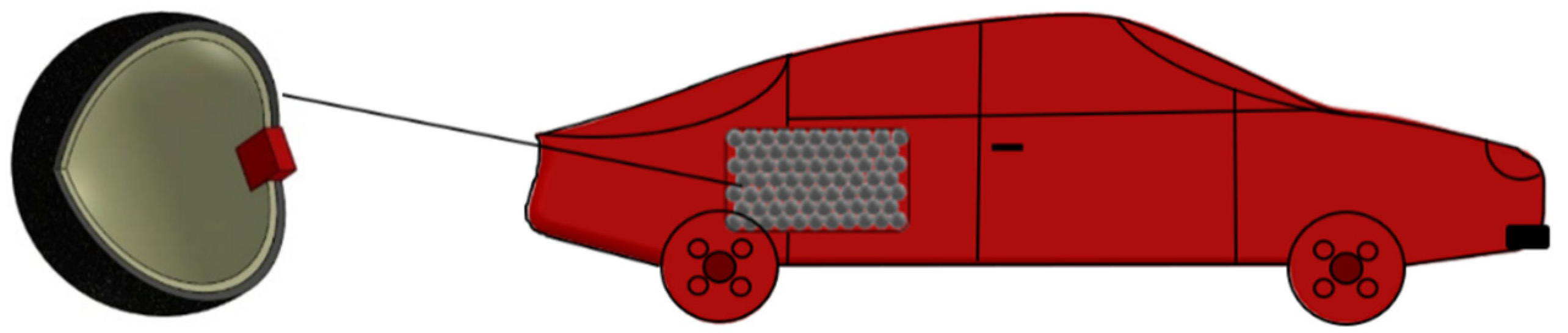
2.1. Storage System Description: Step 1
2.2. Time Variation of Pressure and Mass in Spheres and in Tan: Step 2
- Mass of H2 within a sphere is given by (1),
- Concentration of H2 within a sphere is given by (2) since the mole fraction xH₂ = 1 within the spheres.
- Concentration of H2 within the envelope tank is given by (3) since the mole fraction xH2 = 1 within the envelope tank.
- A part of the inner volume of the envelope tank is occupied by spheres, whose volume is given by (4),Vts = PF × Vint tank.
- Mass of H2 contained in the part of the envelope tank free of spheres is given by (5),
- The permeation coefficient, Φ, of H2 was taken from tables [32]; its value is expressed either by mole/m/s/MPa, or mole/m/s/MPa1/2, or mole/m2/s/MPa1/2.
- The solubility, S, of H2 was calculated as the quotient of H2 by the partial pressure of H2 if the permeation was expressed as mole/m/s/MPa, or as the quotient of H2 by the root of the partial pressure of H2, if the permeation was either expressed as mole/m/s/MPa1/2 or mole/m2/s/MPa1/2. The partial pressure of H2 within the spheres equals the total pressure within the spheres; the partial pressure of H2 within the envelope tank equals the total pressure within it; the H2 in the atmosphere was considered zero.
- The diffusivity, D, of H2 across each layer of the spheres and across the envelope tank was calculated with (6). In the case of the permeability being expressed in mole/m2/s/MPa1/2, which was the case with Si for the microchip, to obtain the diffusivity in m2/s it was necessary to multiply the permeability by the thickness of the layer.Φ = DS.
- Each micro-sphere is made of two concentric spheres, or layers, of different materials, and a parallelepipedal microchip embedded in both spheres; moreover, the outer diameter of the inner sphere equals the inner diameter of the outer sphere. The inner layer, named liner, is mostly intended to provide the necessary resistance to H2 permeation and the outer layer, named structural, is mostly intended to provide structural strength. The permeation flow of H2 from the micro-spheres must not be confounded with the intentional flow of H2 from the spheres, controlled by the microchip, to fuel the propeller (engine or fuel cells). The former occurs in three different ways: by permeation through the spheric layers, by permeation through the microchip, and by the interface between the microchip and the sphere (which is unwanted). This latter flow is leakage and should be as small as possible; since it depends on the quality of the manufacture of the micro-spheres, it is human-controlled and will be neglected. Thus, the overall diffusivity for a micro-sphere is given by (7): it was calculated considering the flow across the series of the composite wall of two concentric spheres (liner and structural) in parallel with the flow across the microchip. As referred, ro liner = ri strut.
- Total resistance to the diffusion of H2 through a micro-sphere was calculated with Equation (8).
- Mole flowrate of H2 through a micro-sphere was calculated by (9); the concentrations of H2 were considered at the inner face of the liner, and at the outer face of the structural layer.
- Masses of H2 within a micro-sphere at the instant t, and at the instant t-Δt are related through (10).
- Concentration of H2 within the envelope tank was obtained through (3) but was considered zero outside it, at the surrounding atmosphere.
- Solubilities of H2 at the inner and outer surface of the envelope tank were calculated according to point 7. The diffusivity of H2 through the envelope tank was calculated according to Equation (6).
- It was assumed a cylindrical enveloped tank, so the total resistance to the diffusion of H2 through the envelope tank was calculated with Equation (11).
- Mole flowrate of H2 through the envelope tank to the atmosphere was calculated by (12), where the concentrations of H2 were considered at the inner face of the envelope tank and at the outer face of the envelope tank; the value of the H2 concentration in the envelope tank was assumed to be zero.
- Masses of H2 within the part of the envelope tank free of micro-spheres at the instant t, and at the instant t-Δt are related through Equation (13).
- At any instant t, the pressure within the micro-spheres or in the part of the envelope tank free of micro-spheres was calculated with the equation of perfect gases. The same was done regarding the H2 concentrations.
2.3. Materials Selection for the Sphere, Tank, and the Values of Permeation: Step 3
2.4. Regulations That Must Be Complied: Step 4
2.5. Aim of Calculations: Step 5
2.6. The Packing Factor (PF): Step 6
3. Results and Discussion
4. Conclusions
Author Contributions
Funding
Institutional Review Board Statement
Informed Consent Statement
Data Availability Statement
Conflicts of Interest
Abbreviations
| List of Symbols | ||
| A | Area | |
| ACH | Air changes per hour | |
| C | Ratio of flowrate of H2 and flowrate of H2 and air | |
| D | Diffusivity | |
| fa | Aging factor | |
| ft | Correction factor for the temperature | |
| GED | Gravimetric energy density | |
| LHV | Low heating value | |
| M | Mass | |
| MW | Molecular weight | |
| Permeation mole flowrate | ||
| N | Number of spheres | |
| P | Pressure | |
| PF | Packing Factor | |
| Q | Flowrate | |
| r | Radius | |
| R | Gas constant, resistance to diffusion | |
| S | Solubility | |
| T | Temperature | |
| t | Time | |
| V | Volume | |
| VED | Volumetric energy density | |
| x | Mole fraction | |
| Z | Compressibility factor | |
| Subscripts | ||
| i | inner | |
| int all sph | Inside all spheres | |
| in sph | Inside the sphere | |
| int tank | Inside the tank | |
| o | outer | |
| p-H2 | Maximum H2 allowable permeation | |
| sph | Sphere | |
| ult | ultimate | |
| u | universal | |
| yield | Yield | |
| Greek Symbols | ||
| Δ | Variation | |
| ρ | Density | |
| σ | Stress | |
| Φ | Permeation coefficient | |
References
- World Bank—Fossil Fuel Energy Consumption Data, Energy Foss Fuels Consum. 2016. Available online: http://data.worldbank.org/indicator/EG.USE.COMM.FO.ZS (accessed on 20 September 2021).
- Strauss, M. EU to Boost Green Hydrogen Use for Decarbonisation, Focus on Energy Efficiency, Reuters. Available online: https://www.reuters.com/article/us-climate-change-eu-hydrogen/eu-to-boost-green-hydrogen-use-for-decarbonisationfocus-on-energy-efficiency-idUSKBN2491JA (accessed on 15 February 2021).
- European Council of the European Union. Available online: https://www.consilium.europa.eu/en/press/press-releases/2020/12/18/paris-agreement-council-transmits-ndc-submission-on-behalf-of-eu-and-member-states/ (accessed on 11 February 2021).
- Herrero, S.T.; Nicholls, L.; Strengers, Y. Smart home technologies in everyday life: Do they address key energy challenges in households? Curr. Opin. Env. Sustain. 2018, 31, 65–70. [Google Scholar] [CrossRef]
- Spiegel, C. Designing and Building Fuel Cells, 1st ed.; McGraw-Hill: New York, NY, USA, 2007; ISBN -13: 978-0-07-148977-5. [Google Scholar]
- Zhang, F.; Zhao, P.; Niu, M.; Maddy, J. The survey of key technologies in hydrogen energy storage. Elsevier Int. J. Hydrog. Energy 2016, 41, 14535–14552. [Google Scholar] [CrossRef]
- Acar, C.; Bicer, Y.; Demir, M.E.; Dincer, I. Transition to a new era with light-based hydrogen production for a carbon-free society: An overview. Int. J. Hydrog. Energy 2019, 44, 25347–25364. [Google Scholar] [CrossRef]
- Dincer, I.; Acar, C. Smart energy solutions with hydrogen options. Int. J. Hydrog. Energy 2018, 43, 8579–8599. [Google Scholar] [CrossRef]
- Nastasi, B.; Lo Basso, G. Hydrogen to link heat and electricity in the transition towards future Smart Energy Systems. Energy 2016, 110, 5–22. [Google Scholar] [CrossRef]
- Europe Hydrogen Refuelling Infrastructure. Available online: https://h2me.eu/about/hydrogen-refuelling-infrastructure/ (accessed on 15 February 2021).
- USA Hydrogen Refuelling Infrastructure. Available online: https://afdc.energy.gov/fuels/hydrogen_locations.html#/find/nearest?fuel=HY (accessed on 11 February 2021).
- O´Hayre, R.; Cha, S.; Colella, W.; Prinz, F. Fuel Cell Fundamentals, 1st ed.; John Wiley & Sons: New York, NY, USA, 2006; ISBN 978-0471741480. [Google Scholar]
- Acar, C.; Bicer, Y. Review and evaluation of hydrogen production options for better environment. J. Clean. Prod. 2019, 218, 835–849. [Google Scholar] [CrossRef]
- Handwerker, M.; Wellnitz, J.; Marzbani, H. Comparison of Hydrogen Powertrains with the Battery Powered Electric Vehicle and Investigation of Small-Scale Local Hydrogen Production Using Renewable Energy. Hydrogen 2021, 2, 76–100. [Google Scholar] [CrossRef]
- Sunliang, C. Comparison of the energy and environmental impact by integrating a H2 vehicle and an electric vehicle into a zero-energy building. Energy Convers. Manag. 2016, 123, 153–173. [Google Scholar]
- Koroma, M.; Brown, N.; Cardellini, G.; Messagie, M. Prospective Environmental Impacts of Passenger Cars under Different Energy and Steel Production Scenarios. Energies 2020, 13, 6236. [Google Scholar] [CrossRef]
- Lys, A.; Fadonougbo, J.; Faisal, M.; Suh, J.; Lee, Y.; Shim, J.; Park, J.; Cho, Y. Enhancing the Hydrogen Storage Properties of AxBy Intermetallic Compounds by Partial Substitution: A Short Review. Hydrogen 2020, 1, 38–63. [Google Scholar] [CrossRef]
- Fonseca, J.D.; Camargo, M.; Commenge, J.-M.; Falk, L.; Gil, I.D. Trends in design of distributed energy systems using hydrogen as energy vector: A systematic literature review. Int. J. Hydrog. Energy 2018, 44, 9486–9504. [Google Scholar] [CrossRef]
- Tarkowski, R. Underground hydrogen storage: Characteristics and prospects. Renew. Sustain. Energy Rev. 2019, 105, 86–94. [Google Scholar] [CrossRef]
- Wei, Q.; Zhang, X.; Oh, B. The effect of driving cycles and H2 production pathways on the lifecycle analysis of hydrogen fuel cell vehicle: A case study in South Korea. Int. J. Hydrog. Energy 2021, 46, 7622–7633. [Google Scholar] [CrossRef]
- Bethoux, O. Hydrogen Fuel Cell Road Vehicles: State of the Art and Perspectives. Energies 2020, 13, 5843. [Google Scholar] [CrossRef]
- Bethoux, O. Hydrogen Fuel Cell Road Vehicles and Their Infrastructure: An Option towards an Environmentally Friendly Energy Transition. Energies 2020, 13, 6132. [Google Scholar] [CrossRef]
- Sapre, S.; Pareek, K.; Rohan, R.; Singh, P. H2 refueling assessment of composite storage tank for fuel cell vehicle. Int. J. Hydrog. Energy 2019, 44, 23699–23707. [Google Scholar] [CrossRef]
- Larminie, J.; Dicks, A. Fuel Cell Systems Explained, 2nd ed.; John Wiley & Sons, Ltd: West Sussex, UK, 2003; ISBN 978-0-470-84857-9. [Google Scholar]
- Baptista, A.; Pinho, C.; Pinto, G.; Ribeiro, L.; Monteiro, J.; Santos, T. Assessment of an Innovative Way to Store Hydrogen in Vehicles. Energies 2019, 12, 1762. [Google Scholar] [CrossRef] [Green Version]
- Stenmark, L. Hydrogen Effects on Silicon Microsystems; (Uppsala University, Sweden). High Pressure Hydrogen Storage. 2009. Available online: https://apps.dtic.mil/sti/citations/ADA504550 (accessed on 3 July 2021).
- European Union. Commission Regulation (EU) No 406/2010 of 26 April 2010 implementing Regulation (EC) No 79/2009 of the European Parliament and of the Council on type-approval of hydrogen-powered motor vehicle. Off. J. Eur. Union 2010, 53, L122/1–L122/107. [Google Scholar]
- Kim, Y.S.; Kim, S.S.; Choe, B.H. The Role of Hydrogen in Hydrogen Embrittlement of Metals: The Case of Stainless Steel. Metals 2019, 9, 406. [Google Scholar] [CrossRef] [Green Version]
- Fu, L.; Fang, H. Formation Criterion of Hydrogen-Induced Cracking in Steel Based on Fracture Mechanics. Metals 2018, 8, 940. [Google Scholar] [CrossRef] [Green Version]
- Adams, P.; Bengaouer, A.; Cariteau, B.; Molkov, V.; Venetsanos, A. Allowable hydrogen permeation rate from road vehicles. Int. J. Hydrog. Energy 2011, 36, 2742–2749. [Google Scholar] [CrossRef]
- Crowl, A.; Jo, Y. The hazards and risks of hydrogen. J. Loss Prev. Process. Ind. 2007, 20, 158–164. [Google Scholar] [CrossRef]
- Barth, R.R.; Simmons, K.L.; San Marchi, C. Polymers for Hydrogen Infrastructure and Vehicle Fuel Systems; In Sandia National Laboratories: Livermore, CA, USA, 2013. [Google Scholar]
- Perry, R.H.; Green, D.W.; Maloney, J.O. Perry’s Chemical Engineers’ Handbook, 7th ed.; McGraw-Hill: New York, NY, USA, 1997; ISBN 0-07-049841-5. [Google Scholar]
- Song, W.; Du, J.; Xu, Y.; Long, B. A study of hydrogen permeation in aluminum alloy treated by various oxidation processes. J. Nucl. Mater. 1997, 246, 139–143. [Google Scholar] [CrossRef]
- Van Deventer, E.H.; Maroni, V.A. Hydrogen permeation characteristics of some austenitic and nickel-base alloys. J. Nucl. Mater. 1980, 92, 103–111. [Google Scholar] [CrossRef]
- Schefer, R.W.; Hout, W.G.; San Marchi, C.; Chernicoff, W.P.; Englom, L. Characterization of leaks from compressed hydrogen dispensing systems and related components. Int. J. Hydrog. Energy 2006, 31, 1247–1260. [Google Scholar] [CrossRef]
- Paiva, L.B.; Morales, A.R.; Guimarães, T.R. Propriedades mecânicas de nanocompósitos de polipropileno e montmorilonita organofílica. Polímeros 2006, 16, 2. [Google Scholar] [CrossRef]
- Paul, D.R. Reformulation of the solution-diffusion theory of reverse osmosis. J. Membr. Sci. 2004, 241, 371–386. [Google Scholar] [CrossRef]
- Humpenoder, J. Gas permeation of fibre reinforced plastics. Cryogenics 1998, 38, 143–147. [Google Scholar] [CrossRef]
- Steward, S.A. Review of Hydrogen Isotope Permeability Through Materials; Lawrence Livermore National Laboratory: Berkeley, CA, USA, 1983. [Google Scholar]
- Suda, H.; Yamauchi, H.; Uchimaru, Y.; Fujiwara, I.; Haraya, K. Preparation and gas permeation properties of silicon carbidebased inorganic membranes for hydrogen separation. Desalination 2006, 193, 252–255. [Google Scholar] [CrossRef]
- Schultheiß, D. Permeation Barrier for Lightweight Liquid Hydrogen Tanks. Ph.D. Thesis, University at Augsburg, Augsburg, Germany, 16 April 2007. [Google Scholar]
- Dwivedi, S.K.; Vishwakarma, M. Hydrogen embrittlement in different materials: A review. Int. J. Hydrog. Energy 2018, 43, 21603–21616. [Google Scholar] [CrossRef]
- Waterland, L.R.; Powars, C.; Stickes, P. Safety Evaluation of the FuelMaker Home Refueling Concept Final Report; National Renewable Energy Laboratory: Golden, CO, USA, 2005. [Google Scholar]
- Mitlitsky, F.; Weisberg, H.A.; Myers, B. Vehicular Hydrogen Storage Using Lightweight Tanks; Lawrence Livermore National Laboratory: Berkeley, CA, USA, 2000. [Google Scholar]
- Moretto, P.; Acosta-Iborra, B.; Baraldi, D.; Galassi, M.; De Miguel, N.; Ortiz Cebolla, R. Onboard Compressed Hydrogen Storage: Fast Filling; IA HySafe and JRC IET Workshop, Research Priorities and Knowledge Gaps in Hydrogen Safety: Berlin, Germany, 2012; pp. 1–15. [Google Scholar]
- Aigueperse, J.; Mollar, P.; Devilliers, D.; Chemla, M.; Faron, R.; Romano, R.; Cuer, J. Fluorine Compounds, Inorganic. In Ullmann’s Encyclopedia of Industrial Chemistry; Wiley: Hoboken, NJ, USA, 2012; Volume 15. [Google Scholar]
- Hales, T.; Ferguson, S. A Formulation of the Kepler Conjecture. Discret. Comput. Geom. 2006, 36, 21–69. [Google Scholar] [CrossRef] [Green Version]
- Hales, T.; Adams, M.; Bauer, G.; Dang, T.; Harrison, J.; Hoang, L.; Zumkeller, R. A Formal Proof of the Kepler Conjecture. Forum Math. 2017, 5, 1–29. [Google Scholar] [CrossRef] [Green Version]
- Dong, K.; Yang, R.; Zou, R.; Yu, A. Role of Interparticle Forces in the Formation of Random Loose Packing. Phys. Rev. Lett. 2006, 96, 145505-1–145505-4. [Google Scholar] [CrossRef]
- Silbert, L. Jamming of frictional spheres and random loose packing. Soft Matter 2010, 13, 2918–2924. [Google Scholar] [CrossRef] [Green Version]
- Onoda, G.; Liniger, E. Random Loose Packings of Uniform Spheres and the Dilatancy Onset. Phys. Rev. Lett. 1990, 64, 2727–2730. [Google Scholar] [CrossRef]
- Saffers, J.B.; Makarov, D.; Molkov, V.V. Modelling and numerical simulation of permeated hydrogen dispersion in a garage with adiabatic walls and still air. Int. J. Hydrog. Energy 2011, 36, 2582–2588. [Google Scholar] [CrossRef]
- Venetsanos, A.G.; Papanikolaou, E.; Cariteau, B.; Adams, P.; Bengaouer, A. Hydrogen permeation from CGH2 vehicles in garages: CFD dispersion calculations and experimental validation. Int. J. Hydrog. Energy 2010, 35, 3848–3856. [Google Scholar] [CrossRef]
- Gentilhomme, O.; Proust, C.; Jamois, D.; Tkatschenko, I.; Cariteau, B.; Studer, E.; Masset, F.; Joncquet, G.; Amielh, M.; Anselmet, F. Data for the evaluation of hydrogen risks onboard vehicles: Outcomes from the French project drive. Int. J. Hydrog. Energy 2012, 37, 17645–17654. [Google Scholar] [CrossRef] [Green Version]


| Step 1 | Storage system description |
| Step 2 | Time variation of pressure and mass in spheres and in tank |
| Step 3 | Materials selection for the sphere, tank, and the values of permeation |
| Step 4 | Regulation that must be complied |
| Step 5 | Aim of calculations |
| Step 6 | The packing factor (PF) |
| Material | Φ | ρ (kgm−3) | σyield (MPa) | σult (MPa) | References | |
|---|---|---|---|---|---|---|
| Al 5050-H38 | 4.34 × 10⁻²⁰ | mol/(msPa0.5) | 2697 | 220 | - | [34] |
| SS316 | 1.13 × 10⁻¹⁸ | mol/(msPa0.5) | 7990 | 290 | - | [35] |
| Inconel 718 | 1.13 × 10⁻¹⁷ | mol/(msPa0.5) | 8190 | 1100 | - | [35] |
| SS403 | 4.34 × 10⁻²⁰ | mol/(msPa0.5) | 7800 | 310 | - | [36] |
| PP | 2.6 × 10⁻¹⁵ | mol/(msPa) | 870 | - | 17.4 | [37,38] |
| HDPE | 8.98 × 10⁻¹⁶ | mol/(msPa) | 1275 | - | 27 | [39] |
| CFEP | 1.9 × 10⁻¹⁶ | mol/(msPa) | 1790 | - | 4000 | [39] |
| W | 4.94 × 10⁻³² | mol/(msPa0.5) | 12,750 | 1045 | [40] | |
| Si | 1 × 10⁻⁸ | mol/(m2sPa0.5) | 3220 | - | - | [41] |
| Combinations | Lining | Structural Layer | Microchip | Envelope Tank |
|---|---|---|---|---|
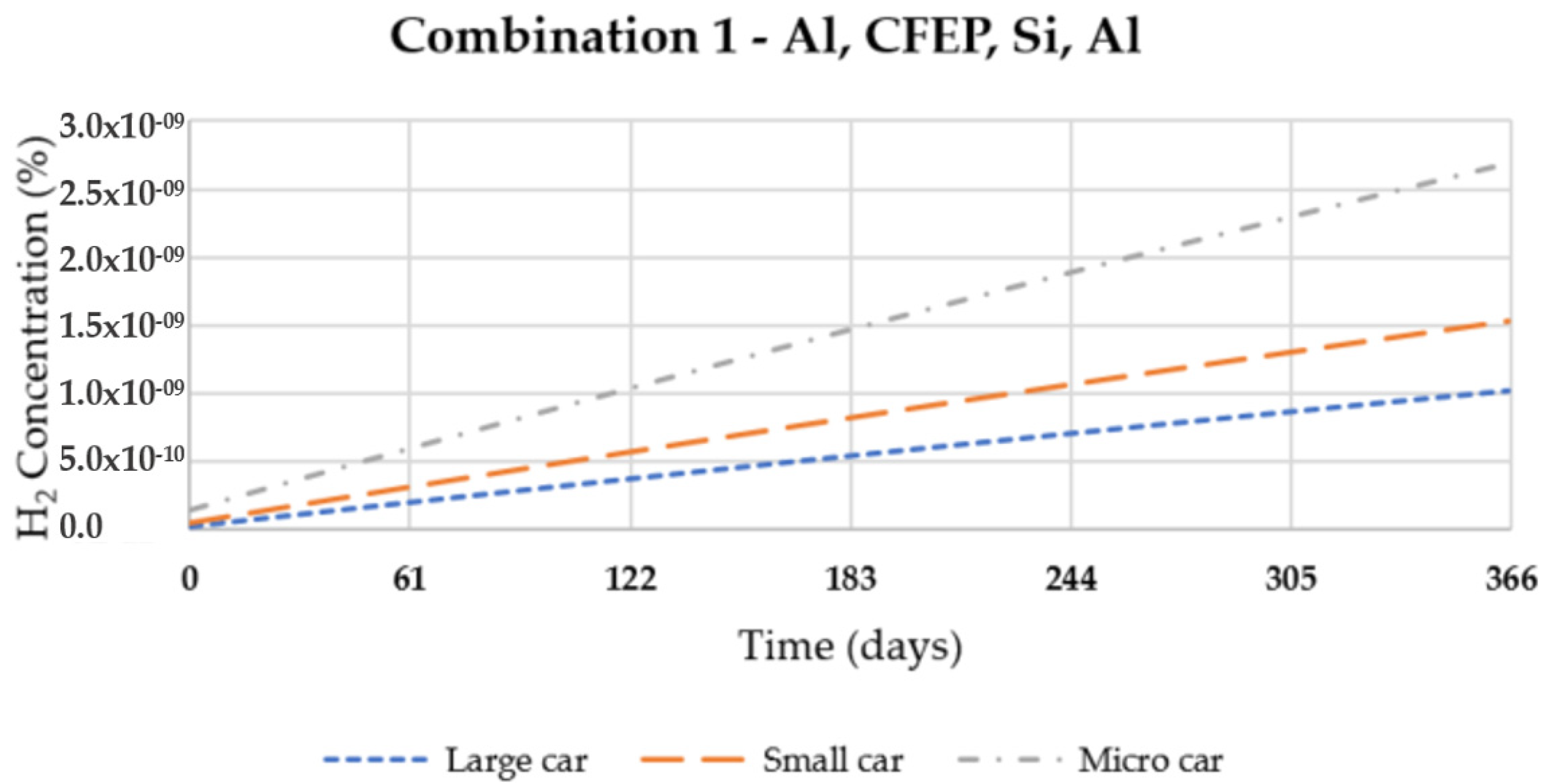
| 1 | Al 5050-H38 | CFEP | Si | Al 5050-H38 |
| 2 | Al 5050-H38 | CFEP | Si | SS316 |
| 3 | Al 5050-H38 | CFEP | Si | SS403 |
| 4 | Al 5050-H38 | CFEP | Si | Inconel 718 |
| 5 | Al 5050-H38 | CFEP | Si | PP |
| 6 | Al 5050-H38 | CFEP | Si | HDPE |
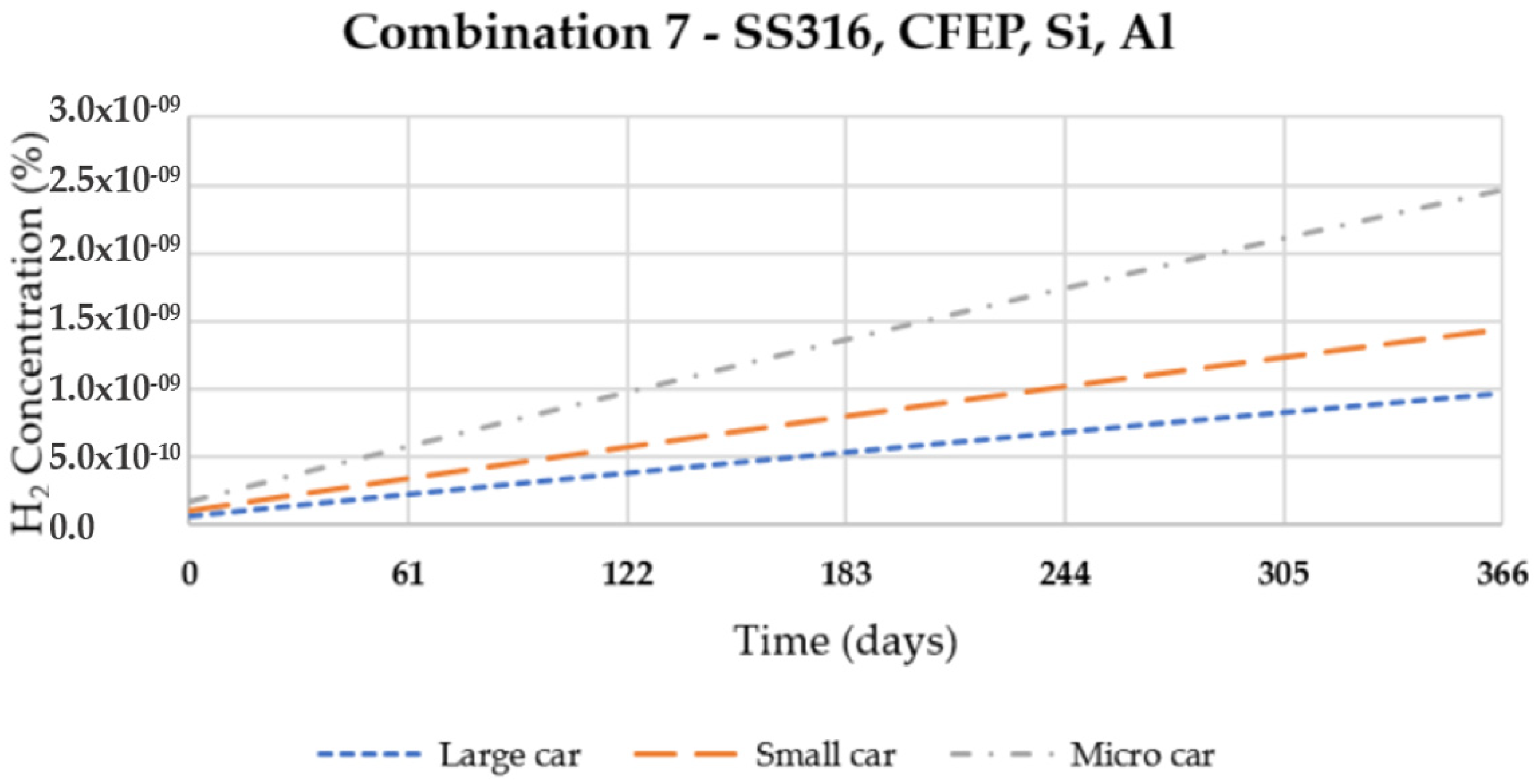
| 7 | SS316 | CFEP | Si | Al 5050-H38 |
| 8 | SS316 | CFEP | Si | SS316 |
| 9 | SS316 | CFEP | Si | SS403 |
| 10 | SS316 | CFEP | Si | Inconel 718 |
| 11 | SS316 | CFEP | Si | PP |
| 12 | SS316 | CFEP | Si | HDPE |
| 13 | SS403 | CFEP | Si | Al 5050-H38 |
| 14 | SS403 | CFEP | Si | SS316 |
| 15 | SS403 | CFEP | Si | SS403 |
| 16 | SS403 | CFEP | Si | Inconel 718 |
| 17 | SS403 | CFEP | Si | PP |
| 18 | SS403 | CFEP | Si | HDPE |
| 19 | W | CFEP | Si | Al 5050-H38 |
| 20 | W | CFEP | Si | SS316 |
| 21 | W | CFEP | Si | SS403 |
| 22 | W | CFEP | Si | Inconel 718 |
| 23 | W | CFEP | Si | PP |
| 24 | W | CFEP | Si | HDPE |
| 25 | PP | CFEP | Si | Al 5050-H38 |
| 26 | PP | CFEP | Si | SS316 |
| 27 | PP | CFEP | Si | SS403 |
| 28 | PP | CFEP | Si | Inconel 718 |
| 29 | PP | CFEP | Si | PP |
| 30 | PP | CFEP | Si | HDPE |
| Features | Scenarios | ||
|---|---|---|---|
| 1 | 2 | 3 | |
| Garage volume (m3) | 50 | 33 | 19 |
| Garage free volume (m3) | 46 | 31 | 18 |
| Volume of impermeable material (m3) | 4 | 2 | 1 |
| Natural ventilation of the garage (ACH) | 0.03 | 0.03 | 0.03 |
| Natural ventilation of the garage (m3/h) | 1.38 | 0.93 | 0.54 |
| Combinations | Elapsed Time (Days) | C% = 100 × QH2/(Qair + QH2) in Garage | ||
|---|---|---|---|---|
| Scenarios | ||||
| 1 | 2 | 3 | ||
| 1 | 79.6 | 2.8 × 10⁻¹⁰ | 4.1 × 10⁻¹⁰ | 7.1 × 10⁻¹⁰ |
| 2 | 79.6 | 1.1 × 10⁻⁸ | 1.6 × 10⁻⁸ | 2.7 × 10⁻⁸ |
| 3 | 79.6 | 1.4 × 10⁻⁵ | 2.1 × 10⁻⁵ | 3.6 × 10⁻⁵ |
| 4 | 79.6 | 3.8 × 10⁻⁷ | 5.6 × 10⁻⁷ | 9.7 × 10⁻⁷ |
| 5 | 82.6 | 3.1 × 10⁻³ | 4.7 × 10⁻³ | 8.0 × 10⁻³ |
| 6 | 80.4 | 8.3 × 10⁻⁴ | 1.2 × 10⁻³ | 2.1 × 10⁻³ |
| 7 | 79.6 | 2.8 × 10⁻¹⁰ | 4.1 × 10⁻¹⁰ | 7.1 × 10⁻¹⁰ |
| 8 | 79.6 | 1.1 × 10⁻⁸ | 1.6 × 10⁻⁸ | 2.7 × 10⁻⁸ |
| 9 | 79.6 | 1.4 × 10⁻⁵ | 2.1 × 10⁻⁵ | 3.6 × 10⁻⁵ |
| 10 | 79.6 | 3.8 × 10⁻⁷ | 5.6 × 10⁻⁷ | 9.7 × 10⁻⁷ |
| 11 | 82.6 | 3.1 × 10⁻³ | 4.7 × 10⁻³ | 8.0 × 10⁻³ |
| 12 | 80.4 | 8.3 × 10⁻⁴ | 1.2 × 10⁻³ | 2.1 × 10⁻³ |
| 13 | 69.4 | 2.8 × 10⁻¹⁰ | 4.1 × 10⁻¹⁰ | 7.1 × 10⁻¹⁰ |
| 14 | 69.4 | 1.1 × 10⁻⁸ | 1.6 × 10⁻⁸ | 2.7 × 10⁻⁸ |
| 15 | 69.4 | 1.4 × 10⁻⁵ | 2.1 × 10⁻⁵ | 3.6 × 10⁻⁵ |
| 16 | 69.4 | 3.8 × 10⁻⁷ | 5.6 × 10⁻⁷ | 9.7 × 10⁻⁷ |
| 17 | 71.8 | 3.1 × 10⁻³ | 4.7 × 10⁻³ | 8.0 × 10⁻³ |
| 18 | 70.0 | 8.3 × 10⁻⁴ | 1.2 × 10⁻³ | 2.1 × 10⁻³ |
| 19 | 79.6 | 2.8 × 10⁻¹⁰ | 4.1 × 10⁻¹⁰ | 7.1 × 10⁻¹⁰ |
| 20 | 79.6 | 1.1 × 10⁻⁸ | 1.6 × 10⁻⁸ | 2.7 × 10⁻⁸ |
| 21 | 79.6 | 1.4 × 10⁻⁵ | 2.1 × 10⁻⁵ | 3.6 × 10⁻⁵ |
| 22 | 79.6 | 3.8 × 10⁻⁷ | 5.6 × 10⁻⁷ | 9.7 × 10⁻⁷ |
| 23 | 82.6 | 3.1 × 10⁻³ | 4.7 × 10⁻³ | 8.0 × 10⁻³ |
| 24 | 80.4 | 8.3 × 10⁻⁴ | 1.2 × 10⁻³ | 2.1 × 10⁻³ |
| 25 | 0.8 | 2.7 × 10⁻¹⁰ | 4.0 × 10⁻¹⁰ | 6.8 × 10⁻¹⁰ |
| 26 | 0.8 | 1.0 × 10⁻⁸ | 1.5 × 10⁻⁸ | 2.6 × 10⁻⁸ |
| 27 | 0.8 | 1.4 × 10⁻⁵ | 2.0 × 10⁻⁵ | 3.5 × 10⁻⁵ |
| 28 | 0.8 | 3.7 × 10⁻⁷ | 5.4 × 10⁻⁷ | 9.4 × 10⁻⁷ |
| 29 | 0.8 | 3.0 × 10⁻³ | 4.5 × 10⁻³ | 7.8 × 10⁻³ |
| 30 | 0.8 | 8.1 × 10⁻⁴ | 1.2 × 10⁻³ | 2.1 × 10⁻³ |
Publisher’s Note: MDPI stays neutral with regard to jurisdictional claims in published maps and institutional affiliations. |
© 2021 by the authors. Licensee MDPI, Basel, Switzerland. This article is an open access article distributed under the terms and conditions of the Creative Commons Attribution (CC BY) license (https://creativecommons.org/licenses/by/4.0/).
Share and Cite
Pinto, G.; Monteiro, J.; Baptista, A.; Ribeiro, L.; Leite, J. Study of the Permeation Flowrate of an Innovative Way to Store Hydrogen in Vehicles. Energies 2021, 14, 6299. https://doi.org/10.3390/en14196299
Pinto G, Monteiro J, Baptista A, Ribeiro L, Leite J. Study of the Permeation Flowrate of an Innovative Way to Store Hydrogen in Vehicles. Energies. 2021; 14(19):6299. https://doi.org/10.3390/en14196299
Chicago/Turabian StylePinto, Gustavo, Joaquim Monteiro, Andresa Baptista, Leonardo Ribeiro, and José Leite. 2021. "Study of the Permeation Flowrate of an Innovative Way to Store Hydrogen in Vehicles" Energies 14, no. 19: 6299. https://doi.org/10.3390/en14196299
APA StylePinto, G., Monteiro, J., Baptista, A., Ribeiro, L., & Leite, J. (2021). Study of the Permeation Flowrate of an Innovative Way to Store Hydrogen in Vehicles. Energies, 14(19), 6299. https://doi.org/10.3390/en14196299