Article

A Study to Investigate the Effect of Valve Mechanisms on Exhaust Residual Gas and Effective Release Energy of a Motorcycle Engine

1
School of Mechanical Engineering, University of Ulsan, San 29, Mugeo2-dong, Nam-gu, Ulsan 44610, Korea
2
Faculty of Automobile Technology, Hanoi University of Industry, No. 298, Cau Dien Street, Bac Tu Liem District, Hanoi 100000, Vietnam
*
Author to whom correspondence should be addressed.
Energies 2021, 14(17), 5564; https://doi.org/10.3390/en14175564
Submission received: 7 August 2021 / Revised: 3 September 2021 / Accepted: 3 September 2021 / Published: 6 September 2021

Abstract

:
The purpose of this study was to investigate the effect of valve mechanisms on the exhaust residual gas (ERG) and effective release energy (ERE) of a motorcycle engine. Here, a simulation model and the estimation a new valve mechanism design is presented. An AVL-Boost simulation model and an experiment system were established. The classical spline approximation method was used to design a new cam profile for various valve lifts. The simulation model was used to estimate the effect of the new valve mechanism designs on engine performance. A new camshaft was produced based on the research data. The results show that the engine obtained a maximum engine brake torque of 21.53 Nm at 7000 rpm, which is an increase of 3.2% compared to the engine using the original valve mechanism. In addition, the residual gas was improved, the maximum engine effective release energy was 0.83 kJ, the maximum engine power was 18.1 kW, representing an improvement of 7.2%, and the air mass flow was improved by 4.97%.

Graphical Abstract

1. Introduction

In the research domain of internal combustion engines, there are two main factors that play an important role: improving engine efficiency and reducing environment pollution. The number of motorcycles in use is constantly increasing; thus, satisfying Euro 5 emission standards and increasing the power of motorcycles is imperative. Typically, to increase engine power and reduce emissions, a new engine design would be considered, including changes in structural parameters such as bore, stroke, combustion chamber geometry, connecting rod length, and compressing ratio, combined with the addition of extra equipment for pollutant emissions. However, for vehicles that have a small SI engine, such as motorcycles, there is limited engine space. It is unrealistic to equip a motorcycle with a bigger engine and an extra system for pollution reduction to improve vehicle performance. Therefore, research is focused on finding other methods for improving power and emission of small engines.
As stated earlier, the goal is to deliver improved engine power and reduce pollutant emissions. Several effective methods can be applied, such as: changing the intake manifold shape [1], using an alternative fuel [2,3], using a fuel injection system instead of a carburetor [4], determining optimal ignition timing [5], recovering lost heat [6], using a supercharger [7], and changing cam profiles [8]. Because valve mechanisms have a significant effect on engine performance and engine emission characteristics, a new valve mechanism design has the potential to improve the engine performance.
The influences of valve lift of an HCCI gasoline engine on the engine performance and emissions were studied by Can Çinar et al. [8]. In this study, the engine was operated from 800 to 1900 rpm, the ratio of air–fuel ranged from 0.5 to 2, and the lifts of the intake and exhaust valves were decreased from 9.5 to 2 mm. A significant effect of the lift of the intake and exhaust valves was found on the experimental results on the HCCI gasoline engine performance and emissions. As the lift of intake valve increased, the air–fuel mixture entering the cylinder increased. When the lift of the intake valve was 5.5 mm, and the lift of the exhaust valve was 3.5 mm, the engine reached a maximum IMEP, of 11 bar. When the engine was operated with a low cam lift, misfire and knocking occurred. A study on the effects of changing valve timing and the cam lift in controlled auto-ignition combustion was presented by Zhang et al. [9]. A one-cylinder engine was used in the experiment. The valve lift was changed from 0.3 to 9.5 mm. It was determined that the rate of heat release and in cylinder pressure was affected by the cam lift. Macklini Dalla Nora et al. [10] presented the effect of valve lift, exhaust back pressure, and valve timing on two-stroke GDI engine performance. In their research, a Ricardo Hydra engine with a variable electrohydraulic valve train was used. The valve mechanics were managed by a Ricardo Cube unit, and the engine was operated from 800 to 2000 rpm. Both the maximum intake valve lift and maximum exhaust valve lift were evaluated in two cases: 3 and 8 mm. The results showed that the valve lift and valve timing had large effects on engine torque. Based on the 25 different valve timings tested, the range of specific torque was from 76 to 185 Nm/dm3. At an engine speed of 2000 rpm, the air trapping efficiency was reduced by 17% when the intake valve lift increased from 3 to 8 mm, and was reduced by 12% when the exhaust valve lift increased from 3 to 8 mm. This indicates that increasing the size of the valve lifts results in a decreased amount of fresh air–fuel mixture that enters the cylinder. As a result, the engine torque is also increased. Can Cinar et al. [11] found that the valve lifts have a significant effect on the performance of an engine using either LPG fuel or gasoline fuel. The authors increased the valve lift from 6.5 to 8 mm. The classical spline method was used to redesign the camshaft for different valve lifts. When using the redesigned camshaft, the volumetric efficiency was improved. Using the same valve lift at 7 mm, the gasoline engine brake torque increased 8.82%, and BSFC decreased 7.25%, compared to the LPG fuel engine. However, in the engine using LPG as fuel, the HC and CO emissions were decreased. The results of this research also showed that, at the valve lift of 8 mm, the engine brake torque, brake specific fuel consumption, CO emissions, and HC emissions were improved. Kaimin Liu et al. [12] presented the effect of asynchronous valve timing on engine performance and combustion characteristics. An SI marine engine with five valves was used in a high-speed experiment. The results showed that the valve timing had a significant effect on the gas exchange and the volumetric efficiency. The engine’s torque and the brake specific fuel consumption (BSFC) were improved when the intake opening valve was higher than 20 degrees CA. The HC and CO emissions were decreased, but CO2 and NOx levels were increased.
In the above studies, the maximum valve lift was increased to improve engine power. However, no articles have examined the effect of valve lifts on the exhaust residual gas (ERG) and effective release energy (ERE). This is a gap in the research relating to valve mechanics that the current study aimed to address.
In this paper, a reliable simulation model and experimental system were established. A more effective cam profile was designed, based on a 28 mm diameter basic circle and a 190 degree cam angle, while maintaining the maximum valve lifts. The optimization of the valve mechanisms is a direct and effective means to improve the power of a small SI engine. The simulation model and experimental system were used to study the effect of the valve mechanisms on the ERG, ERE, and engine performance.

2. Methodology of the Study

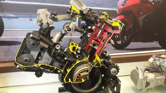
2.1. Experimental Setup

The engine experimental schematic and system are shown in Figure 1 and Figure 2, respectively. In the experimental setup a dynamo controller (1) was used to control the speed of the dynamo (MCA325MO2) (2); the coupling (3) was used to reduce sudden moments when starting the engine (4). The encoder (E40S8-1800-3-T-24) (6) and the thermal sensor (7) were used to measure engine speed and knock. The fuel supply system includes the fuel tank (8), filter (10), pump (9), and injectors (11). The air intake system includes the purifier box (15), throttle (16), heater (17), and temperature sensor (18). In the exhaust gas system housed the oxygen sensor (12) and temperature sensor (13). The cylinder pressure was determined based on sensor (14). The monitor (19), ECU (20), data acquisition (21), and computer (22) were used to analyze and observe output data.
The experiment conditions used a compression ratio of 11.8:1, an air–fuel ratio of 13.6, and an ambient temperature of the testing system from 29.5 to 30 °C. Air was used as a coolant; the oil temperature of the engine is maintained at 80 °C. The fuel pressure was maintained from 333 to 363 kPa, and the angle of throttle was 100% (opening). All the apparatus were calibrated before analysis.
A spark-ignition engine was used out to obtained the experiment results. The specifications of the experimental engine are shown in Table 1.

2.2. Simulation Method

AVL-Boost is a powerful software package used for simulating all types of internal combustion engines, including SI engines [15], CI engines [16,17], 4 stroke engines [18], and engines using alternative fuel [19]. The simulation model of a small SI engine is shown in Figure 3.
Figure 3 presents the engine simulation model. The element restrictions (R1, R2, and R3) displayed the pressure loss of the intake and exhaust tube (1, 2, 3…21). To collect or distribute the air flow through the pipe, the element junctions (J1, J2, J3, J5, and J6) were used. The measurements at the elements MP1 and MP2 were used to determine the flow characteristic (e.g., air-mass flow, air-flow velocity, air-flow temperature) in the intake and exhaust pipes. To supply fuel to cylinders C1 and C2, injectors I1 and I2 were used.
The combustion model was defined as follows:
The heat release rate was defined by the Vibe function [20]:
d x d α = a Δ α ( m + 1 ) y m . e a . y ( m + 1 )
d x = d Q h Q h ; y = α α 0 Δ α c
where:
α: crankshaft-angle (deg);
α0: start combustion (deg);
m: parameter of shape (-);
a: Vibe’s parameter (-).
The faction burned in mass ε can be calculated [20] as:
ε = d x d α d α = 1 e α . y ( m + 1 )
The heat transfer of combustion chamber was calculated [20] as:
Q T = A . q c o e f f . ( T c T w )
where:
QT: Combustion heat loss (W/m2);
A: Surface area (m2);
Tc and Tw: Combustion and cylinder wall temperature (K).

2.3. Development Process

Figure 4 shows the steps taken to design the new valve mechanism using a simulation program and an experimental system. Two cycles were used. The first cycle (black cycle) was to develop the simulation model based on the original engine. The second cycle (red cycle) was the design and optimization process. The redesigned parameters were first estimated based on the simulation model. If the simulation results matched the target, then the new camshaft was manufactured; this new camshaft was estimated again via the experiments before being applied to the engine.
The input parameters (including valve lifts, valve timing, valve overlap, ignition angle, air–fuel ratio, and throttle opening angle) were changed to study the subsequent effects on engine characteristics. Based on that process, we determined the optimal input parameters for providing the target results and making new, more effective products. The next step was verification of these parameters using the experimental setup.
The mass flow of air has a significant effect on the engine performance. With an increase in the mass flow of air entering the cylinder, while holding the air–fuel ratio constant, the mass of fuel injected into the combustion chamber is increased. This leads to an increase in the maximum pressure in the combustion chamber; as a result, the engine torque is higher. Several methods to increase the engine power have been presented, such as reducing the intake air restriction, or reducing the tube bending in the intake system and increasing the diameter of the intake port. A method was proposed to increase air mass flow entering the combustion chamber via a new valve mechanism design.
Equations (4) and (5) show how valve lifts affect air mass flow into the cylinder
Flow coefficient (Cf) [20]:
C f = Q A s e a t . V 0
V 0 = 2 . Δ P ρ
A s e a t = π 4 D 2 ;
Coefficient of discharge (Cd) [20]:
C d = Q A V . V 0 A V = n . π D 2 . L D . C o s 1 + L D s i n . c o s
The cam profiles for different valve lifts were determined by the 5th degree classical spline method. Equation (6) shows the function of the finite time difference [11].
S θ = a θ χ t χ 2 + b θ χ t χ 2 + c θ χ t χ 2 + d θ χ t χ 2 + e θ χ t χ 2 + f ( χ θ t )
where:
θ: Cam angle (deg);
χ: the start timings (sec);
t: the end timings (sec).
The basic circle diameter of the cam profile is 28 mm. The cam angle is 190 degrees, and the maximum valve lift is 6.5 mm for the intake valves and 6.4 mm for the exhaust valves. A successful design of valve mechanisms ensures smooth and effective cam profiles. C. Çınar et al. [11]. changed valve lifts using a 5th degree classical spline method. They were able to reduce the point contact of the cam profile. Design parameters for camshafts with new valve lifts have been calculated using the functions with finite differences in time [8,21,22,23]. In Figure 5, the black curve defines the valve lift (mm), as measured on the vertical axis. The red curve defines the cam velocity (mm/deg) at an engine speed of 5000 rpm, and is equal to five times the value on the vertical axis. The blue curve defines the cam acceleration (mm/deg2), which is equal to two thousand times the value on the vertical axis. Using the first-order derivative of the movement with respect to the cam angle, the new cam velocity curve was defined with a maximum value of 6.4 mm/deg. Using the second-order derivative of the movement with respect to the cam angle, the profile of acceleration was defined with a maximum value of 0.0485 mm/deg2.

3. Results and Discussions

3.1. Model Validation

In this study, the experimental data were used to validate the simulation model. The results of the experiment and simulation model are compared and depicted in Figure 6. The validation values are presented in Table 2. The experimental results are expressed as the black curve and the simulation results are expressed as the red curve.
Figure 6 represents the validation of ignition timing in both cases at an engine speed of 5000 rpm. Regarding ignition timing, the values of the experiment and simulation model were equal because the ignition timing and combustion duration were provided manually in the simulation model. Regarding air mass flow, a comparison between the results of the experiment and the simulation model is depicted. The maximum difference was 1.42%. This maximum difference is acceptable because the value of air mass flow was an average value during the experiment. The experimental and simulation results of the brake torque of the two cases were similar. The maximum difference was 0.9%. The results of the comparison of the two cases support the simulation model; the simulation model had good accuracy in terms of predicting ERG and ERE in further studies.

3.2. Simulation Results

After verifying the simulation model, the effects of the new valve mechanisms on engine performance were studied. A comparison between the two cases (case 1 is the simulation with the original design, and case 2 is the simulation with the new design) was undertaken.
Figure 7 shows the effect flowchart for the main factors that affect engine torque and engine power.
This effect flow chart shows that:
-
Engine bore, stroke, and connecting rod length affect the total displacement volume VD;
-
Valve lifts and lengths, diameters of intake tube, air–fuel ratio, and ignition timing affect the air mass flow, ERG, and ERE;
-
The air mass flow affects the brake specific fuel (BSFC), and indicates the mean affective pressure (IMEP) and the fuel consumption (ISFC).
-
VD has a direct influence on the engine effective torque (Teff) as described in Equation (7).
T e f f = B M E P . V D K c y c l e . π B M E P = B S F C . I M E P I S F C
The higher engine speed leads to an increase in the air mass flow, as shown in Figure 8. The values for air mass flow in case 2 (with the new valve mechanism) were higher than in case 1 at each engine speed. The difference was less within the engine speed range from 3000 to 6000 rpm. This indicates that, at low and medium engine speeds, the effects of the new valve mechanism on air mass flow are small. However, when the engine speed was between 7000 and 10,000 rpm, the difference in air mass flow increased. This may be explained because the effects of the new valve mechanisms on air mass flow are larger than those at low speeds. In turn, this is because, at high speeds, the vacuum pressure in the intake cylinder was greater than that at low and medium speeds.
The minimum variation in air mass flow between the two cases was 2.73% at 3000 rpm, and the maximum variation was 4.48% at 10,000 rpm.
In the intake stroke, the increase in intake air mass flow into the combustion chamber helps to sweep burned gas outside, resulting in the decrease in ERG, as observed in Figure 9. The internal exhaust residual gas is trapped in the combustion chamber because the reverse burned gas flows back to the combustion chamber through the intake or exhaust ports. This ERG premix with the fresh air–fuel mixture and affect combustion stability, charge mass, flame speed, and emission of toxic products in the next combustion stroke. The ERG flow can be controlled by changing intake valve timing, exhaust valve timing, and valve overlap (the valve timings were controlled by valve mechanisms). The ERG has a significant effect on the engine performance and emission characteristics [17], and a suitable amount of high temperature ERG helps to improve the homogeneity of the air–fuel mixture, thereby improving the combustion. By comparison, the increase on ERG leads to an increase in the dilution of the air–fuel mixture, resulting in a reduction in the burning temperature. The decrease in the burning temperature helps to improve NOx emissions. Thus, it is necessary to investigate the effect of the valve mechanisms on the exhaust residual gas.
In the internal combustion engine, the effective release energy is determined based on the remaining energy after losing heat energy due to transfer and pumping loss. To improve the heat energy, the combustion duration should be reduced and a faster release het energy is required to reduce heat transfer loss. As discussed previously, a suitable ERG helps to improve the homogeneity of the air–fuel mixture, thus reducing the combustion duration and reducing the heat transfer loss. Hence, the effective release energy increases until reaching the maximum value at 7000 rpm, before subsequently decreasing. Figure 10 presents the effect of the new cam design on the ERE at each engine speed. With the new valve mechanics, the engine presents a higher ERE value. The maximum ERE was 0.835 kJ at 7000 rpm, representing an improvement of 15%. This improvement in ERE can be explained because the decrease in ERG helps to decrease the dilution and increase the homogeneity of the air–fuel mixture, thus helping to reduce the time required to release the chemical energy into thermal energy, and the time for the heat loss transfer within the cylinder and piston surfaces. When the engine speed was higher than 7000 rpm, the effect of the ERG on improving the homogeneity of the air–fuel mixture was smaller. In addition, the increase in the combustion duration led to an increase in the heat loss, resulting in a downward trend in the effective release energy.
The ERE had a significant effect on engine torque; similar trends for ERE and engine torque can be observed in Figure 10 and Figure 11. The engine torque increased until achieving a maximum value at 7000 rpm, after which it declined. Figure 11 shows the effects of the cam profile on engine torque. With the new cam design, engine torque was improved at every engine speed due to the increase in ERE and the reduction in heat loss. The engine was able to achieve a maximum torque of 21.9 Nm at 7000 rpm, representing an increase of 3.3%.
The engine brake power is strongly dependent on the engine brake torque and engine speed. The uptrend of engine power following the increase in engine speed is presented in Figure 12. Due to the improvement in engine brake torque, a higher engine brake power with the new cam design is presented compared to that of the original cam. The maximum power was 18.01 KW at 9000 rpm, an increase of 7.84%. The trends of the BSFC in the two cases were similar, but the BSFC value in case 2 was smaller than that in case 1 (Figure 13) due to the higher engine power of case 1. The minimum BSFC of both cases occurred at 7000 rpm. With the new cam design, the minimum BSFC was 338.86 g/KWh, a decrease of 6.15% compared to that of the original cam profile.

3.3. New Valve Mechanisms Verification by Doing Experiments

A new cam was constructed based on the classical spline method, with a basic circle having a diameter of 28 diameter, a cam angle of 190 degrees, a maximum intake valve lift of 6.5 mm, and an exhaust valve lift of 6.4 mm. As discussed in Section 3.2, a simulation model was used to estimate the effects of the new cam shaft on the engine performance. Data from the new cam design were used for computer-aided design, and cams were manufactured from AISI-SAE 4140 steel by Computer Numerical Control wire erosion machining. The new camshaft is shown in Figure 14.
This new camshaft was applied to the motorcycle engine. The effect of the new camshaft on engine performance was verified by experiments.
An improvement in engine torque with the new camshaft can be observed in Figure 15. The maximum engine torque was 21.53 Nm at 7000 rpm, an increase of 3.2%. The maximum engine power was 18.1 KW at 9000 rpm, an increase of 7.2%, as shown in Figure 16.

4. Conclusions

In this research, the effects of valve mechanics on ERG, ERE, and engine performance of a motorcycle engine were investigated. Successful simulation modeling and an experimental system helped to save time and reduce cost, and provided a convenient and powerful method for optimizing parameters. In this research, a new camshaft was manufactured and applied to a motorcycle engine. The simulation results were in good agreement with the experimental results. Therefore, it was feasible to use the simulation model to study the effects on engine performance. The small SI engine using the new design achieved a maximum engine brake torque of 21.53 Nm, an increase of 3.2%. Using the new valve mechanics, the ERG was reduced and the ERE was improved. The engine achieved the maximum ERE of 0.835 kJ at 7000 rpm, representing an improvement of 15%. The maximum power was 18.1 kW, an increase of 7.2%. The maximum air mass flow was increased by 4.97% and the minimum BSFC was 338.86 g/KWh, representing a decrease of 6.15%.

Author Contributions

Conceptualization, N.X.K.; methodology, N.X.K.; software, N.X.K.; validation, N.X.K.; resources, N.X.K.; writing—original draft preparation, N.X.K.; writing—review and editing, N.X.K.; supervision, O.L.; project administration, O.L. All authors have read and agreed to the published version of the manuscript.

Funding

This research is financially supported by the individual basic research project by the National Research Foundation of Korea (NRF-2021R1F1A1048238, Reliability Improvement of Ammonia-Diesel Dual-Fuel Combustion Model regarding Optimized Combustion Strategy for Improved Combustion Efficiency and Emission Characteristics).
This research is financially supported by the Shipbuilding and Offshore Industry Core Technology Development Business by the Ministry of Trade, Industry and Energy (MOTIE, Korea) [Development of Low Print Point Alternative Fuel Injection System for Small and Medium Vessel Engines for Ships Hazardous Emission Reduce]. (20013146).

Institutional Review Board Statement

Not applicable.

Informed Consent Statement

Not applicable.

Data Availability Statement

Not applicable.

Conflicts of Interest

The authors declare no conflict of interest.

References

  1. Pogorevc, P.; Kegl, B. Intake and exhaust influence on engine performance. J. KONES Intern. Combust. Engines 2004, 11, 125–132. [Google Scholar]
  2. Sui, W.; González, J.P.; Hall, C.M. Combustion Phasing Modelling of Dual Fuel Engines. IFAC-PapersOnLine 2018, 51, 319–324. [Google Scholar] [CrossRef]
  3. Li, Y.; Gong, J.; Deng, Y.; Yuan, W.; Fu, J.; Zhang, B. Experimental comparative study on combustion, performance and emissions characteristics of methanol, ethanol and butanol in a spark ignition engine. Appl. Therm. Eng. 2017, 115, 53–63. [Google Scholar] [CrossRef]
  4. Wei, H.; Shao, A.; Hua, J.; Zhou, L.; Feng, D. Effects of applying a Miller cycle with split injection on engine performance and knock resistance in a downsized gasoline engine. Fuel 2018, 214, 98–107. [Google Scholar] [CrossRef]
  5. Jung, D.; Iida, N. An investigation of multiple spark discharge using multi-coil ignition system for improving thermal efficiency of lean SI engine operation. Appl. Energy 2018, 212, 322–332. [Google Scholar] [CrossRef]
  6. Rajeevan, J.; Hans, M.; Joseph, A.; Kiran, T.; Thampi, G.K. Hybrid Turbocharged SI engine with Cooled Exhaust Gas Recirculation for Improved Performance. Procedia Technol. 2016, 24, 444–451. [Google Scholar] [CrossRef] [Green Version]
  7. Lee, J.; Park, C.; Kim, Y.; Choi, Y.; Bae, J.; Lim, B. Effect of turbocharger on performance and thermal efficiency of hydrogen-fueled spark ignition engine. Int. J. Hydrogen Energy 2019, 44, 4350–4360. [Google Scholar] [CrossRef]
  8. Cinar, C.; Uyumaz, A.; Solmaz, H.; Topgul, T. Effects of valve lift on the combustion and emissions of a HCCI gasoline engine. Energy Convers. Manag. 2015, 94, 159–168. [Google Scholar] [CrossRef]
  9. Zhang, Y.; Zhao, H.; Xie, H.; He, B.-Q. Variable-valve-actuation-enabled high-efficiency gasoline engine. Proc. Inst. Mech. Eng. Part D J. Automob. Eng. 2010, 224, 1081–1095. [Google Scholar] [CrossRef]
  10. Nora, M.D.; Lanzanova, T.; Zhao, H. Effects of valve timing, valve lift and exhaust backpressure on performance and gas exchanging of a two-stroke GDI engine with overhead valves. Energy Convers. Manag. 2016, 123, 71–83. [Google Scholar] [CrossRef] [Green Version]
  11. Çinar, C.; Şahin, F.; Can, Ö.; Uyumaz, A. A comparison of performance and exhaust emissions with different valve lift profiles between gasoline and LPG fuels in a SI engine. Appl. Therm. Eng. 2016, 107, 1261–1268. [Google Scholar] [CrossRef]
  12. Liu, K.; Yang, J.; Jiang, W.; Li, Y.; Wang, Y.; Feng, R.; Chen, X.; Ma, K. Effect of asynchronous valve timing on combustion characteristic and performance of a high speed SI marine engine with five valves. Energy Convers. Manag. 2016, 123, 185–199. [Google Scholar] [CrossRef]
  13. Khoa, N.X.; Lim, O. The effects of combustion duration on residual gas, effective release energy, engine power and engine emissions characteristics of the motorcycle engine. Appl. Energy 2019, 248, 54–63. [Google Scholar] [CrossRef]
  14. Khoa, N.; Lim, O. The Internal Residual Gas and Effective Release Energy of a Spark-Ignition Engine with Various Inlet Port–Bore Ratios and Full Load Condition. Energies 2021, 14, 3773. [Google Scholar] [CrossRef]
  15. Khoa, N.X.; Lim, O. Comparative Study of the Effective Release Energy, Residual Gas Fraction, and Emission Characteristics with Various Valve Port Diameter-Bore Ratios (VPD/B) of a Four-Stroke Spark Ignition Engine. Energies 2020, 13, 1330. [Google Scholar] [CrossRef] [Green Version]
  16. Rubio, J.A.P.; Vera-García, F.; Grau, J.H.; Cámara, J.M.; Hernandez, D.A. Marine diesel engine failure simulator based on thermodynamic model. Appl. Therm. Eng. 2018, 144, 982–995. [Google Scholar] [CrossRef]
  17. Melaika, M.; Rimkus, A.; Vipartas, T. Air Restrictor and Turbocharger Influence for the Formula Student Engine Performance. Procedia Eng. 2017, 187, 402–407. [Google Scholar] [CrossRef]
  18. Khoa, N.X.; Nhu, Y.Q.; Lim, O. Estimation of parameters affected in internal exhaust residual gases recirculation and the influence of exhaust residual gas on performance and emission of a spark ignition engine. Appl. Energy 2020, 278, 115699. [Google Scholar] [CrossRef]
  19. Praptijanto, A.; Muharam, A.; Nur, A.; Putrasari, Y. Effect of Ethanol Percentage for Diesel Engine Performance Using Virtual Engine Simulation Tool. Energy Procedia 2015, 68, 345–354. [Google Scholar] [CrossRef] [Green Version]
  20. AVL. Theory AVL BOOST. 2017. Available online: https://www.avl.com/boost (accessed on 20 May 2018).
  21. Yao, M.; Zheng, Z.; Liang, X. Numerical study on the Chemical Reaction Kinetics of DME/Methanol for HCCI Combustion Process. SAE Tech. Pap. 2006, 12. [Google Scholar] [CrossRef]
  22. Nguyen, V.-T.; Kim, D.-J. Flexible cam profile synthesis method using smoothing spline curves. Mech. Mach. Theory 2007, 42, 825–838. [Google Scholar] [CrossRef]
  23. Lampinen, J. Cam shape optimization by genetic algorithm. Comput. Aided Des. 2003, 35, 727–737. [Google Scholar] [CrossRef]
Figure 1. Schematic of the engine experimental setup [13].
Energies 14 05564 g001
Figure 2. The experimental system.
Energies 14 05564 g002
Figure 3. Engine simulation model [13].
Energies 14 05564 g003
Figure 4. Flowchart of the research.
Energies 14 05564 g004
Figure 5. The displacement, velocity, and acceleration curves of the new cam design.
Energies 14 05564 g005
Figure 6. Model validation.
Energies 14 05564 g006
Figure 7. Effect flow chart.
Energies 14 05564 g007
Figure 8. Comparison of air mass flow between the original and new valve mechanisms.
Energies 14 05564 g008
Figure 9. Comparison of ERG between the original and new valve mechanisms.
Energies 14 05564 g009
Figure 10. Comparison of ERE between the original and new valve mechanisms.
Energies 14 05564 g010
Figure 11. Comparison of brake torque between the original and new valve mechanism.
Energies 14 05564 g011
Figure 12. Comparison of engine power between the original and new valve mechanisms.
Energies 14 05564 g012
Figure 13. Comparison of engine power between the original and new valve mechanisms.
Energies 14 05564 g013
Figure 14. The new camshaft.
Energies 14 05564 g014
Figure 15. Comparison of brake torque between the original and new valve mechanisms.
Energies 14 05564 g015
Figure 16. Comparison of engine power between the original and new valve mechanisms.
Energies 14 05564 g016
Table 1. The specifications of testing engine [14].
SpecificationsUnitValues
Cylinder-number-2
Compression-ratio-11.8:1
Bore-strokeMm57–53.8
Connecting-rodMm107.9
Intake-valves-2
Exhaust-valves-2
Table 2. The validation values.
Experimental ValueSimulation ValueUnit
Ignition timing2828Deg
Air-mass flow1615g/s
Peak pressure rise21.5Bar/deg
Peak temperature23002200K
Engine brake torque18.718.3Nm
NOx emission99.2g/kWh
Publisher’s Note: MDPI stays neutral with regard to jurisdictional claims in published maps and institutional affiliations.

