
Real-Time Energy Management for DC Microgrids Using Artificial Intelligence

 , , , , ,
Abstract
:
1. Introduction
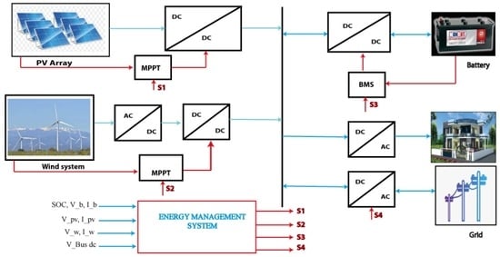
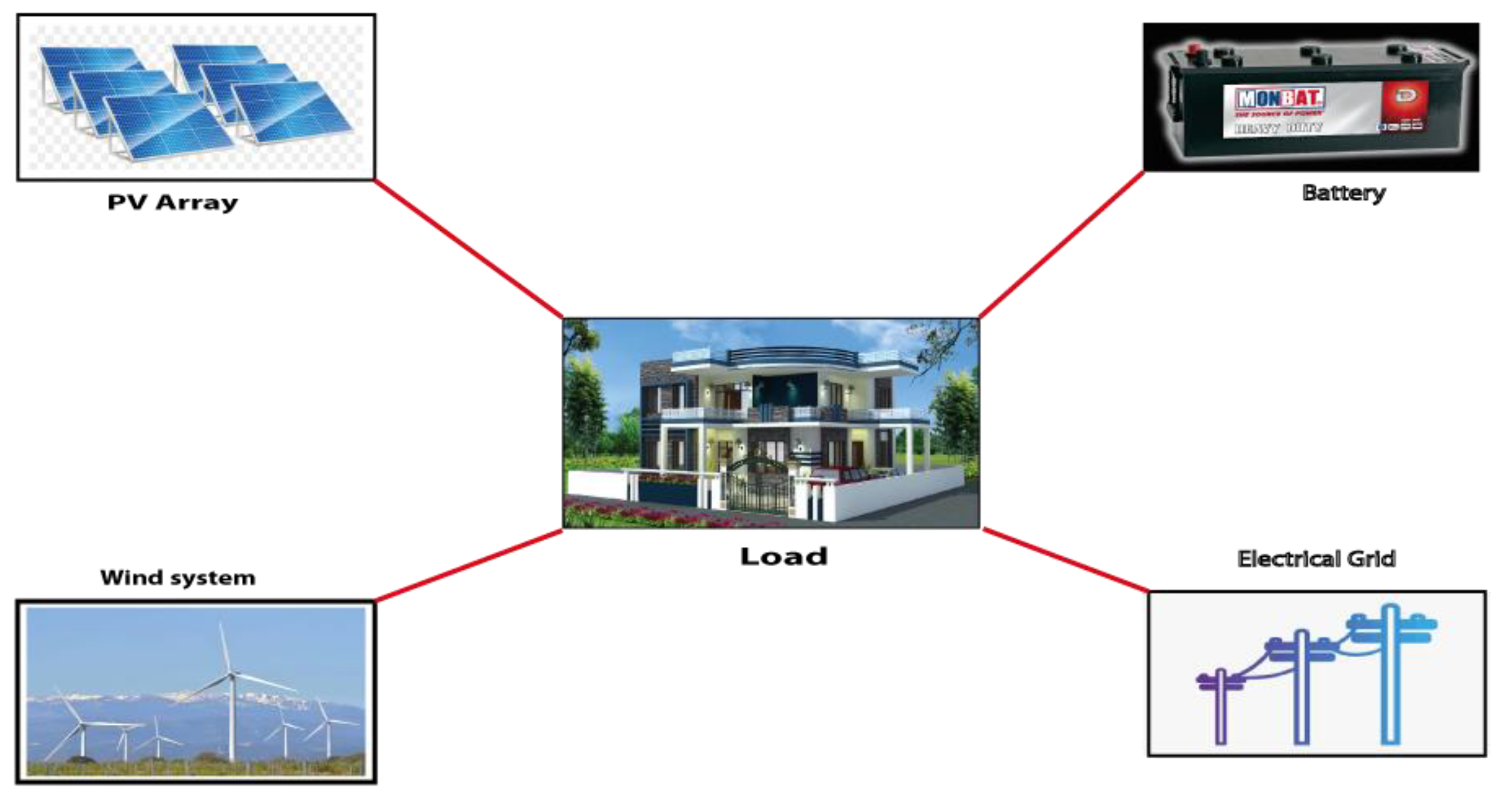
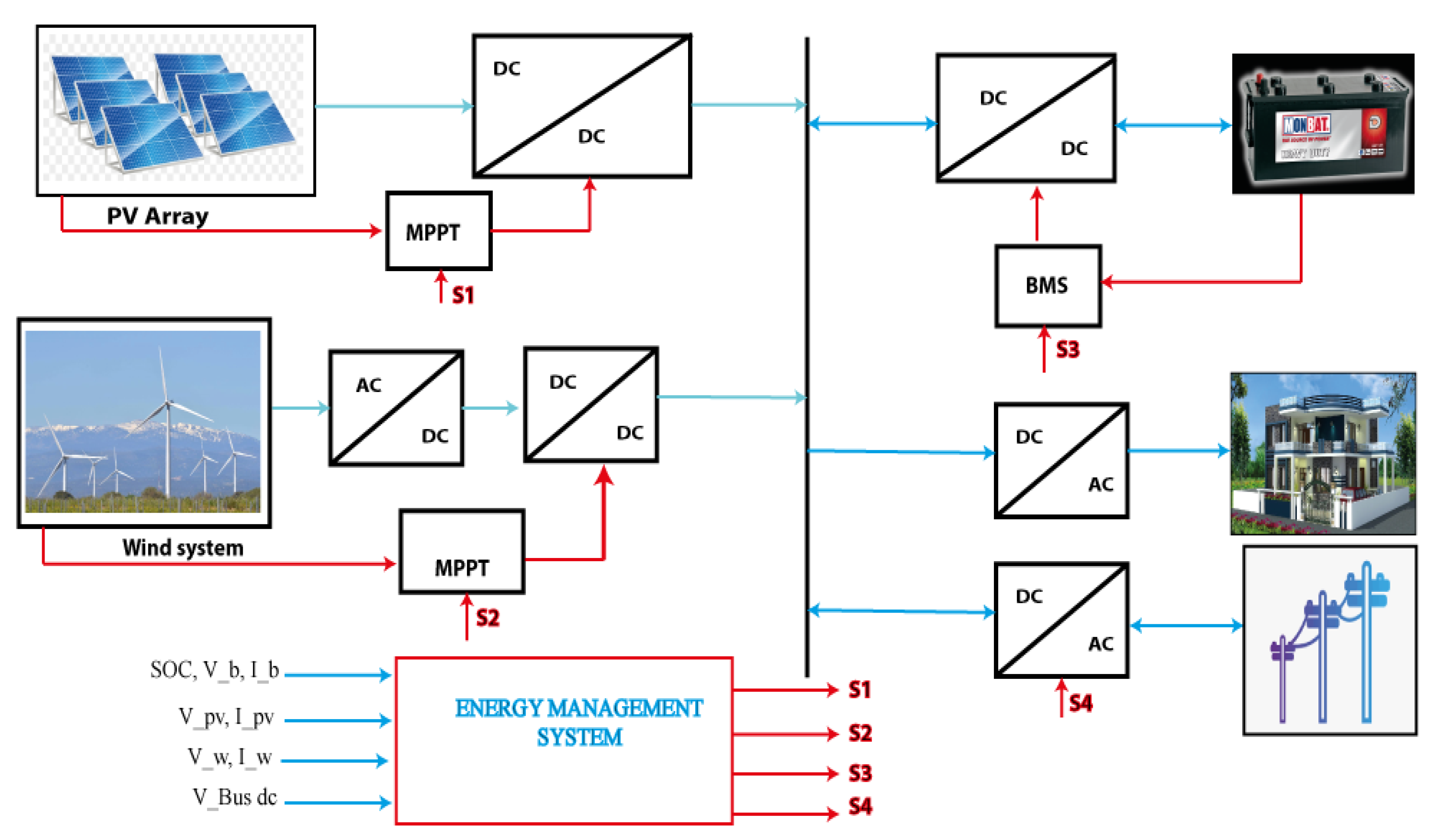
2. Microgrid System
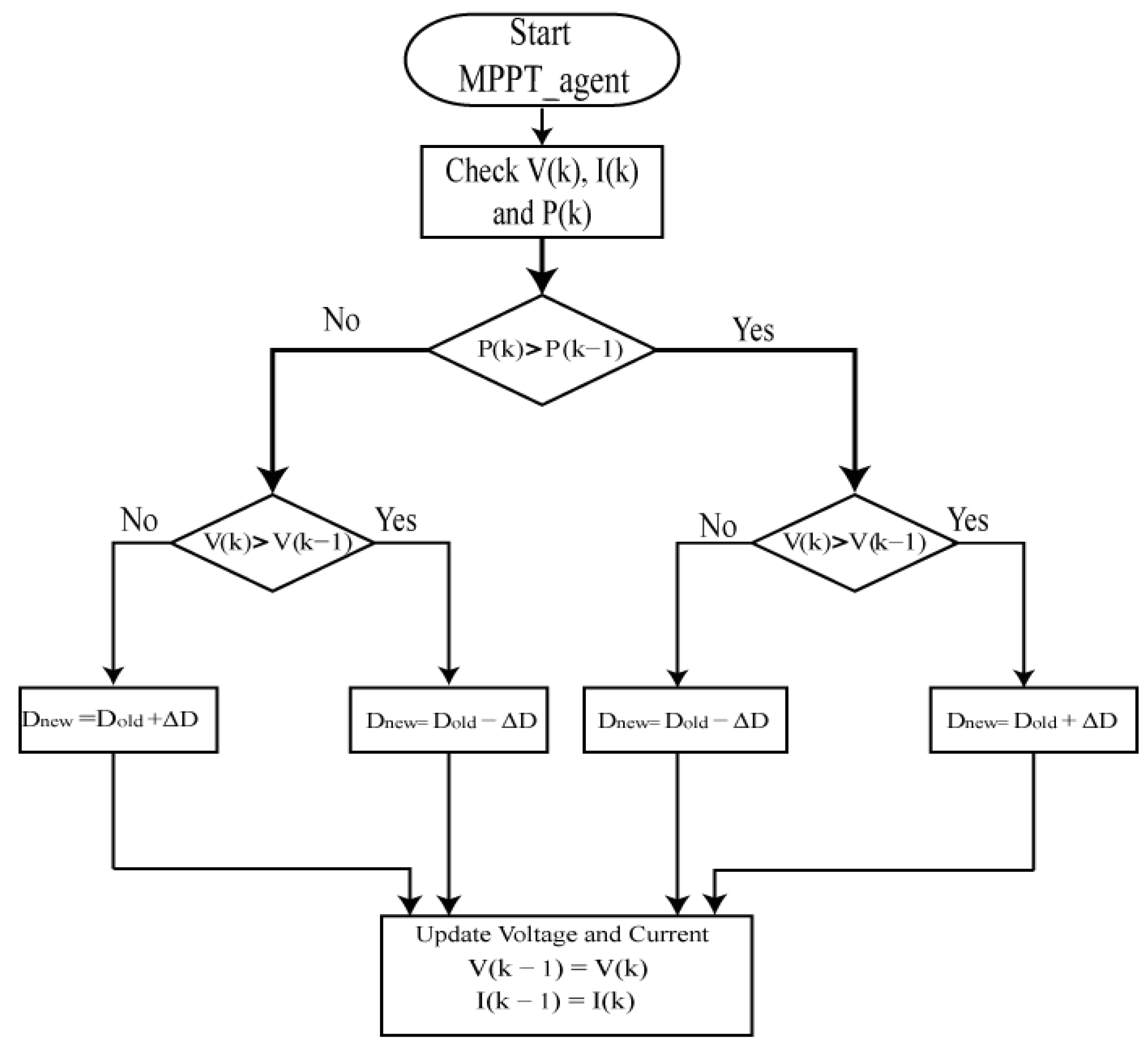
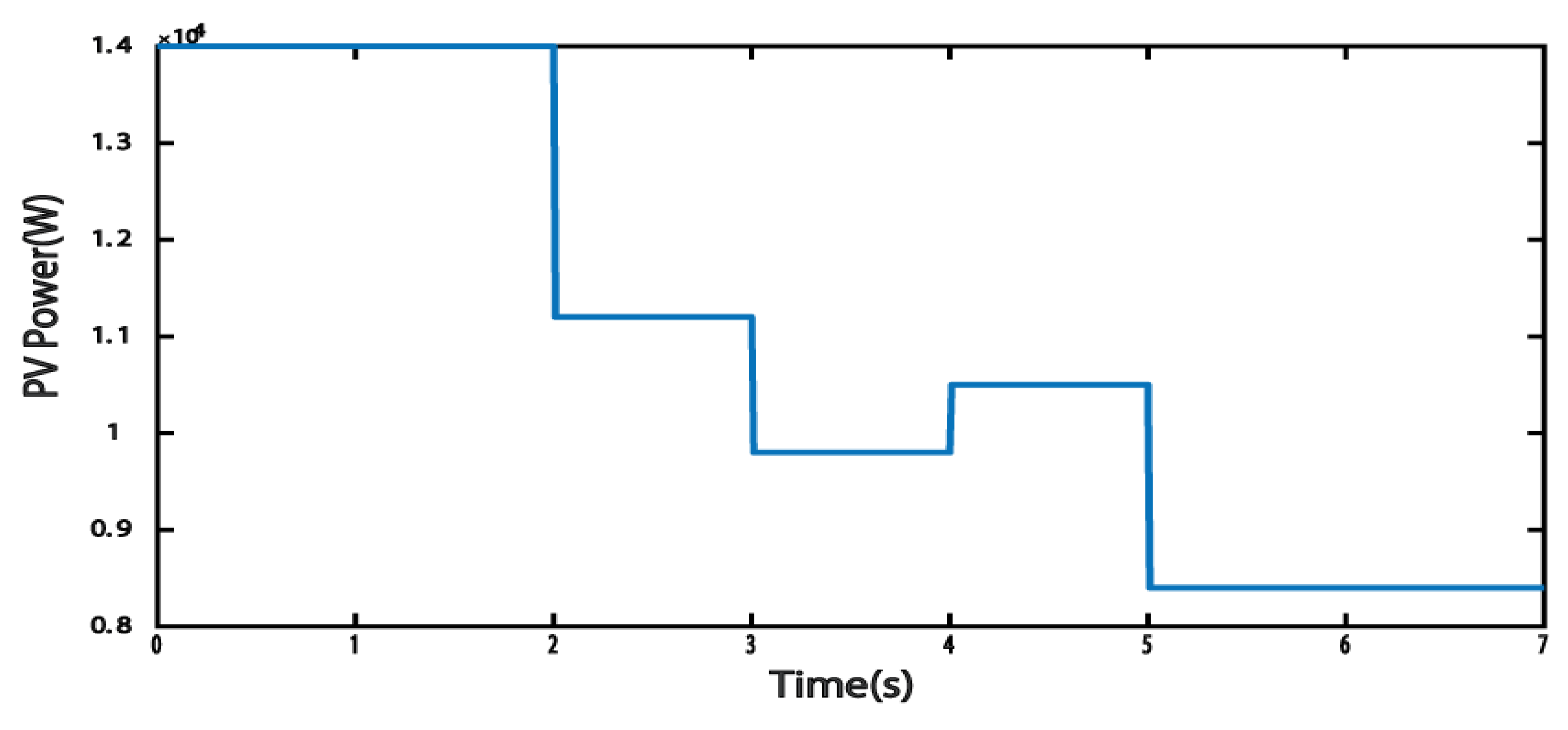
2.1. Photovoltaic System
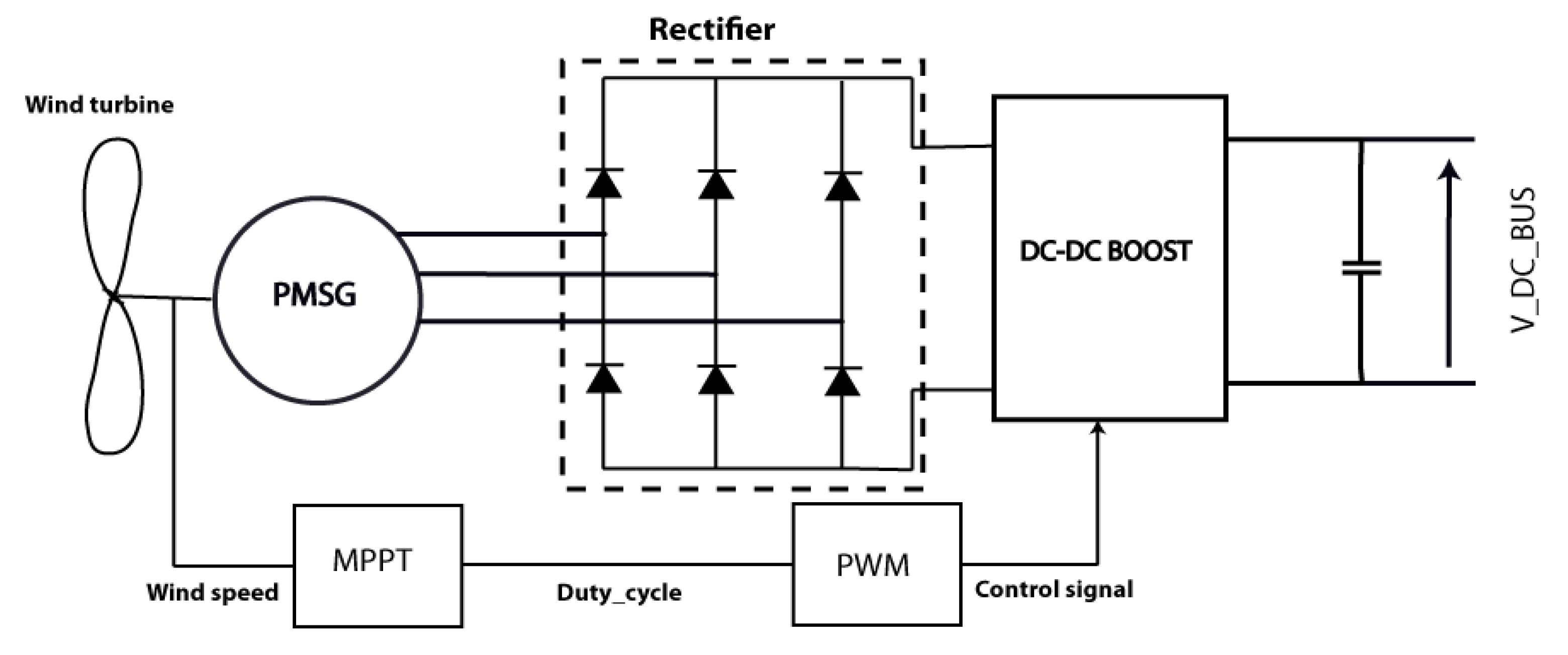
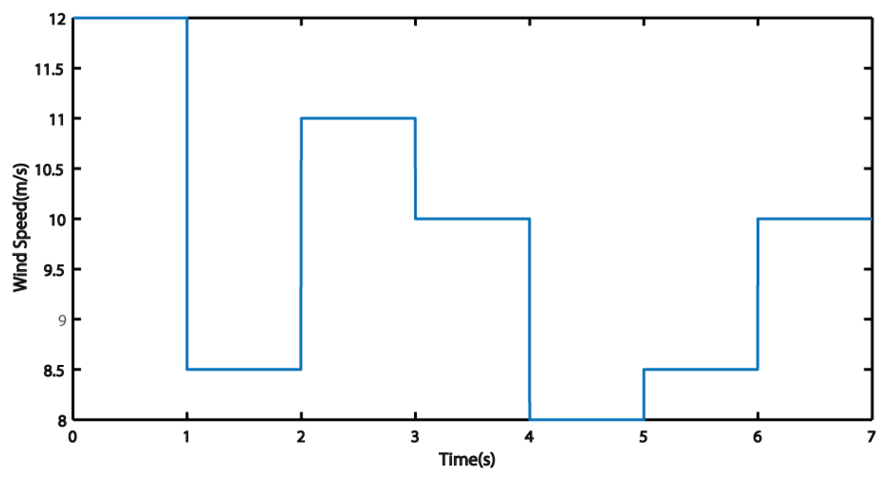
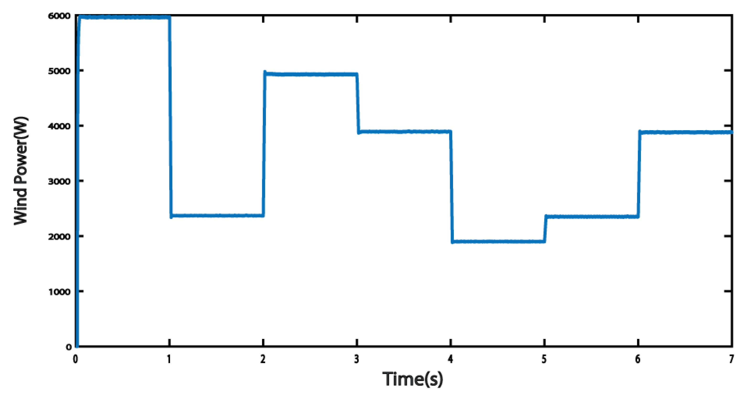
2.2. Wind System
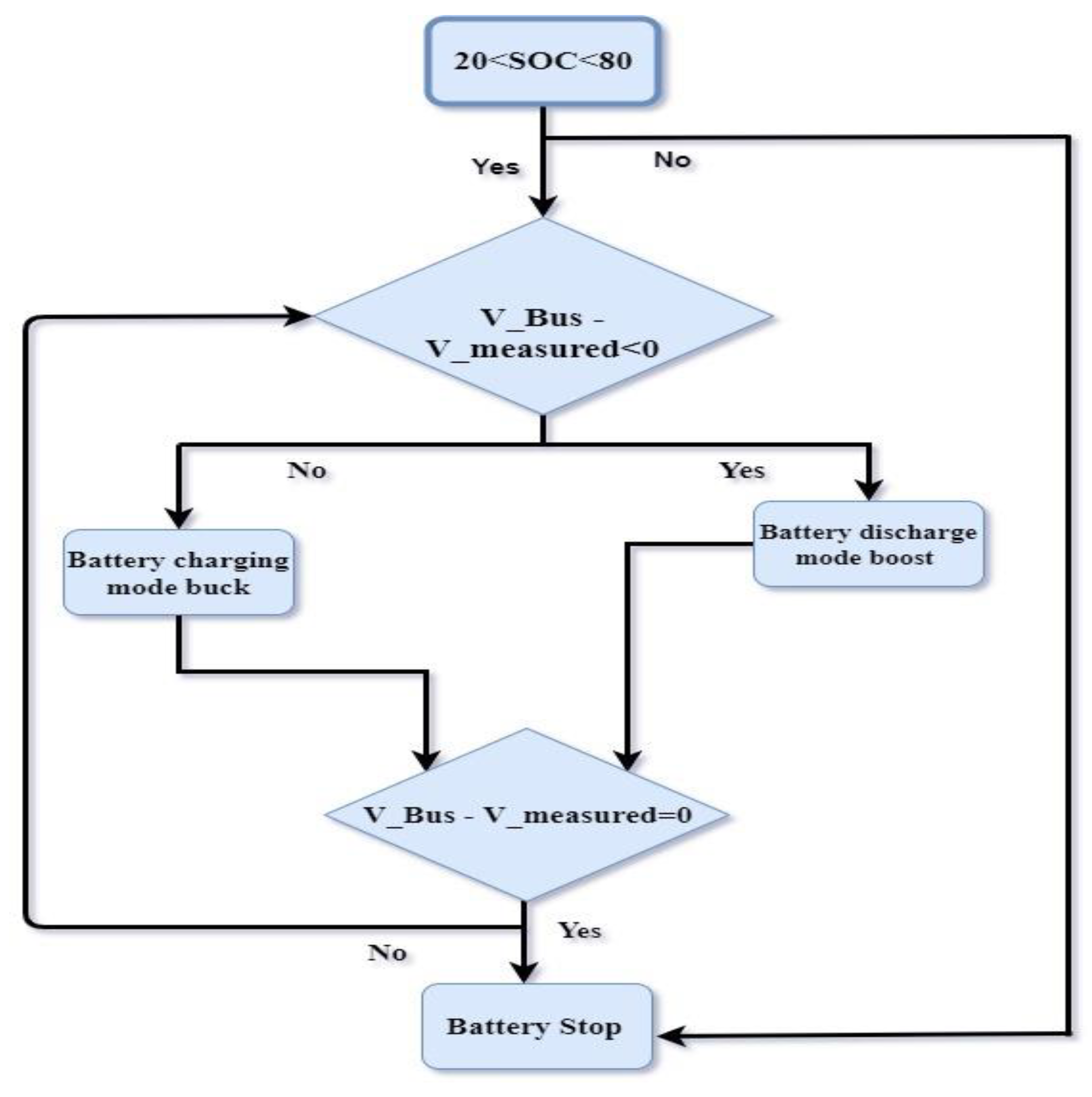
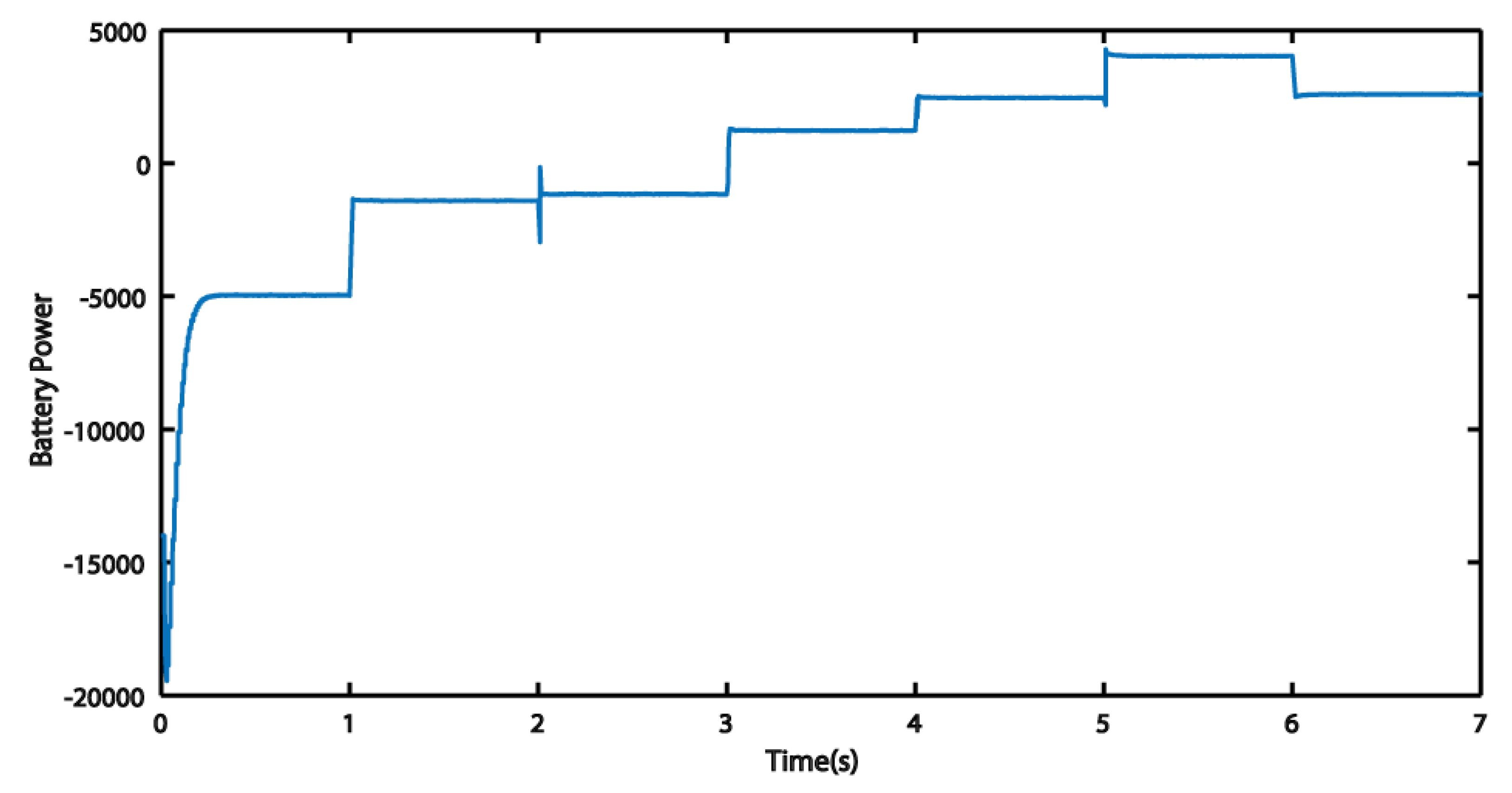
2.3. Battery Storage System
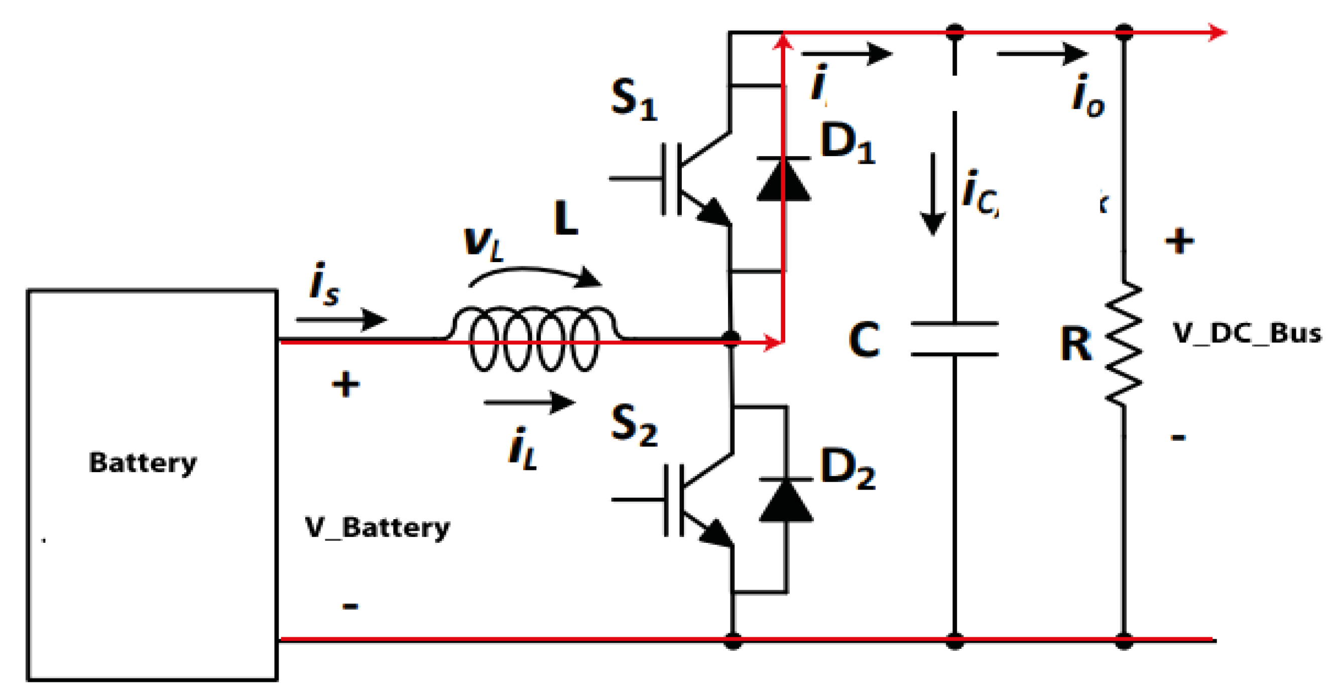
- ➢ Buck Mode
- ➢ Boost Mode
3. Multi-Agent Framework and Energy Management System
3.1. Multi-Agent Framework and Co-Simulation MATLAB/JADE
3.2. Energy Management System
4. Results and Discussion
5. Conclusions
Author Contributions
Funding
Institutional Review Board Statement
Informed Consent Statement
Data Availability Statement
Conflicts of Interest
References
- Gerlach, A.-K.; Stetter, D.; Schmid, J.; Breyer, C. PV and wind power-complementary technologies. In Proceedings of the 26th European Photovoltaic Solar Energy Conference, Hamburg, Germany, 5–9 September 2011. [Google Scholar]
- Rekioua, D. Hybrid Renewable Energy Systems: Optimization and Power Management Control; Springer Nature: Basingstoke, UK, 2019. [Google Scholar]
- Singh, A.R.; Lei, D.; Kumar, A.; Singh, R.; Meena, N.K. Microgrid system. In Microgrid: Operation, Control, Monitoring and Protection; Springer: Singapore, 2020; pp. 1–25. [Google Scholar]
- Cheng, Z.; Duan, J.; Chow, M.-Y. To centralize or to distribute: That is the question: A comparison of advanced microgrid management systems. IEEE Ind. Electron. Mag. 2018, 12, 6–24. [Google Scholar] [CrossRef]
- Meng, L.; Sanseverino, E.R.; Luna, A.; Dragicevic, T.; Vasquez, J.C.; Guerrero, J.M. Microgrid supervisory controllers and energy management systems: A literature review. Renew. Sustain. Energy Rev. 2016, 60, 1263–1273. [Google Scholar] [CrossRef]
- Karavas, C.S.; Kyriakarakos, G.; Arvanitis, K.G.; Papadakis, G. A multi-agent decentralized energy management system based on distributed intelligence for the design and control of autonomous polygeneration microgrids. Energy Convers. Manag. 2015, 103, 166–179. [Google Scholar] [CrossRef]
- Rodriguez, R.J.; Zeller, R.J.; Skertic, R.J.; Dougherty, M.P.; Cline, C.H. Micro Grid Control System. U.S. Patent No. 10,530,163, 7 January 2020. [Google Scholar]
- Sood, V.K.; Ali, M.Y.; Khan, F. Energy management system of a microgrid using particle swarm optimization (PSO) and communication system. In Microgrid: Operation, Control, Monitoring and Protection; Springer: Singapore, 2020; pp. 263–288. [Google Scholar]
- Gao, H.; Xu, S.; Liu, Y.; Wang, L.; Xiang, Y.; Liu, J. Decentralized optimal operation model for cooperative microgrids considering renewable energy uncertainties. Appl. Energy 2020, 262, 114579. [Google Scholar] [CrossRef]
- Bogaraj, T.; Kanakaraj, J. Intelligent energy management control for independent microgrid. Sādhanā 2016, 41, 755–769. [Google Scholar] [CrossRef] [Green Version]
- Boudoudouh, S.; Maâroufi, M. Multi agent system solution to microgrid implementation. Sustain. Cities Soc. 2018, 39, 252–261. [Google Scholar] [CrossRef]
- Aung, H.; Khambadkone, A.; Srinivasan, D.; Logenthiran, T. Agent-based intelligent control for real-time operation of a microgrid. In Proceedings of the 2010 Joint International Conference on Power Electronics, Drives and Energy Systems & 2010 Power India, New Delhi, India, 20–23 December 2010. [Google Scholar]
- Logenthiran, T.; Srinivasan, D.; Khambadkone, A.M.; Aung, H.N. Multiagent system for real-time operation of a microgrid in real-time digital simulator. IEEE Trans. Smart Grid 2012, 3, 925–933. [Google Scholar] [CrossRef]
- Hlaili, M.; Mechergui, H. Comparison of different MPPT algorithms with a proposed one using a power estimator for grid connected PV systems. Int. J. Photoenergy 2016, 2016, 1728398. [Google Scholar] [CrossRef] [Green Version]
- Boujoudar, Y.; Azeroual, M.; El Moussaoui, H.; Lamhamdi, T. Intelligent controller based energy management for stand-alone power system using artificial neural network. Int. Trans. Electr. Energy Syst. 2020, 30, e12579. [Google Scholar]
- Tremblay, O.; Dessaint, L.-A.; Dekkiche, A.-I. A generic battery model for the dynamic simulation of hybrid electric vehicles. In Proceedings of the 2007 IEEE Vehicle Power and Propulsion Conference, Arlington, TX, USA, 9–12 September 2007; pp. 284–289. [Google Scholar]
- Tremblay, O.; Dessaint, L.-A. Experimental validation of a battery dynamic model for EV applications. World Electr. Veh. J. 2009, 3, 289–298. [Google Scholar] [CrossRef] [Green Version]
- Boujoudar, Y.; Elmoussaoui, H.; Lamhamdi, T. Lithium-Ion batteries modeling using NARX Nonlinear model. In Proceedings of the 2019 International Conference on Wireless Technologies, Embedded and Intelligent Systems (WITS), Fez, Morocco, 3–4 April 2019. [Google Scholar]
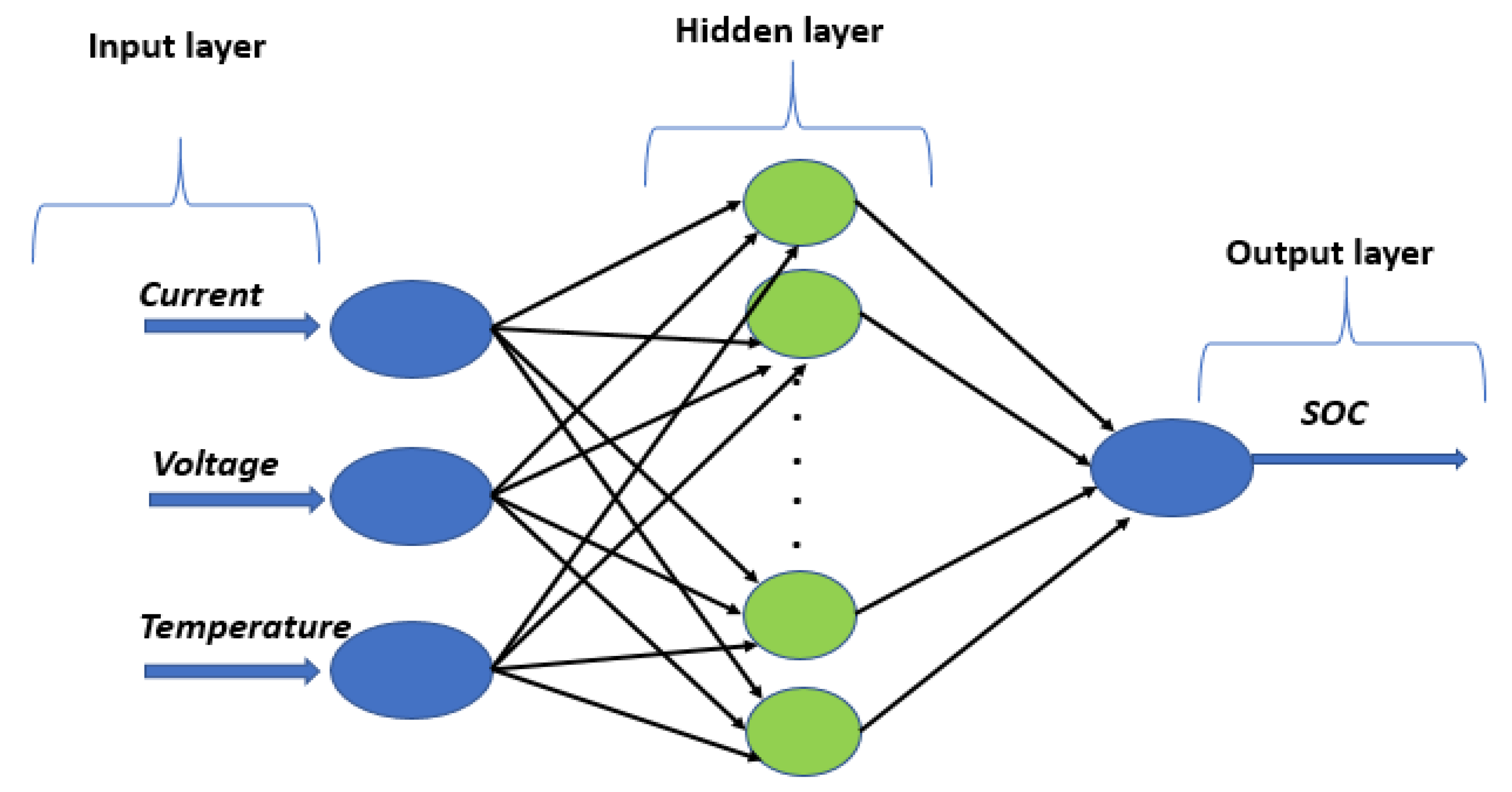
- Boujoudar, Y.; Elmoussaoui, H.; Lamhamdi, T. Lithium-ion batteries modeling and state of charge estimation using artificial neural network. Int. J. Electr. Comput. Eng. 2019, 9, 3415–3422. [Google Scholar] [CrossRef]
- Oprea, M. Applications of multi-agent systems. In Information Technology; Springer: Boston, MA, USA, 2004; pp. 239–270. [Google Scholar]
- Habib, H.F.; Youssef, T.; Cintuglu, M.H.; Mohammed, O.A. Multi-agent-based technique for fault location, isolation, and service restoration. IEEE Trans. Ind. Appl. 2017, 53, 1841–1851. [Google Scholar] [CrossRef]
- Robinson, C.R.; Mendham, P.; Clarke, T. MACSimJX: A tool for enabling agent modelling with Simulink using JADE. J. Phys. Agents 2010, 4, 1–7. [Google Scholar] [CrossRef] [Green Version]
- Boudoudouh, S.; Maâroufi, M. Real-time battery state of charge estimation in smart grid application by multi agent system. Int. J. Hydrog. Energy 2017, 42, 19487–19495. [Google Scholar] [CrossRef]
- Bellifemine, F.; Poggi, A.; Rimassa, G. Developing multi-agent systems with a FIPA-compliant agent framework. Softw. Pract. Exp. 2001, 31, 103–128. [Google Scholar] [CrossRef]
- Azeroual, M.; Lamhamdi, T.; El Moussaoui, H.; El Markhi, H. Simulation tools for a smart grid and energy management for microgrid with wind power using multi-agent system. Wind. Eng. 2019, 44, 661–672. [Google Scholar] [CrossRef]


| Agents | Task Description |
|---|---|
| PV MPPT agent |
|
| Wind turbine MPPT agent |
|
| Load agent |
|
| Battery agents |
|
| Electrical grid agent |
|
| Symbol | Specification |
|---|---|
| DC_BUS | V = 220 V; P = 15 KW |
| BATTERY | V = 48 V; Q_BATT = 320 AH |
| PV PANEL | P_PV = 14 KW, V_PV = 400 V |
| WIND TURBINE | P_W = 14 KW, |
| LOAD | P_LDC + P_LAC = 15 KW |
| ELECTRICAL GRID | P_GRID = 15 KW |
Publisher’s Note: MDPI stays neutral with regard to jurisdictional claims in published maps and institutional affiliations. |
© 2021 by the authors. Licensee MDPI, Basel, Switzerland. This article is an open access article distributed under the terms and conditions of the Creative Commons Attribution (CC BY) license (https://creativecommons.org/licenses/by/4.0/).
Share and Cite
Albarakati, A.J.; Boujoudar, Y.; Azeroual, M.; Jabeur, R.; Aljarbouh, A.; El Moussaoui, H.; Lamhamdi, T.; Ouaaline, N. Real-Time Energy Management for DC Microgrids Using Artificial Intelligence. Energies 2021, 14, 5307. https://doi.org/10.3390/en14175307
Albarakati AJ, Boujoudar Y, Azeroual M, Jabeur R, Aljarbouh A, El Moussaoui H, Lamhamdi T, Ouaaline N. Real-Time Energy Management for DC Microgrids Using Artificial Intelligence. Energies. 2021; 14(17):5307. https://doi.org/10.3390/en14175307
Chicago/Turabian StyleAlbarakati, Aiman J., Younes Boujoudar, Mohamed Azeroual, Reda Jabeur, Ayman Aljarbouh, Hassan El Moussaoui, Tijani Lamhamdi, and Najat Ouaaline. 2021. "Real-Time Energy Management for DC Microgrids Using Artificial Intelligence" Energies 14, no. 17: 5307. https://doi.org/10.3390/en14175307
APA StyleAlbarakati, A. J., Boujoudar, Y., Azeroual, M., Jabeur, R., Aljarbouh, A., El Moussaoui, H., Lamhamdi, T., & Ouaaline, N. (2021). Real-Time Energy Management for DC Microgrids Using Artificial Intelligence. Energies, 14(17), 5307. https://doi.org/10.3390/en14175307