
Energy and Exergy Efficiency Analysis of Fluid Flow and Heat Transfer in Sinter Vertical Cooler


Abstract
:1. Introduction
2. Analysis of Energy and Exergy Efficiency
3. Description of Simulation Model
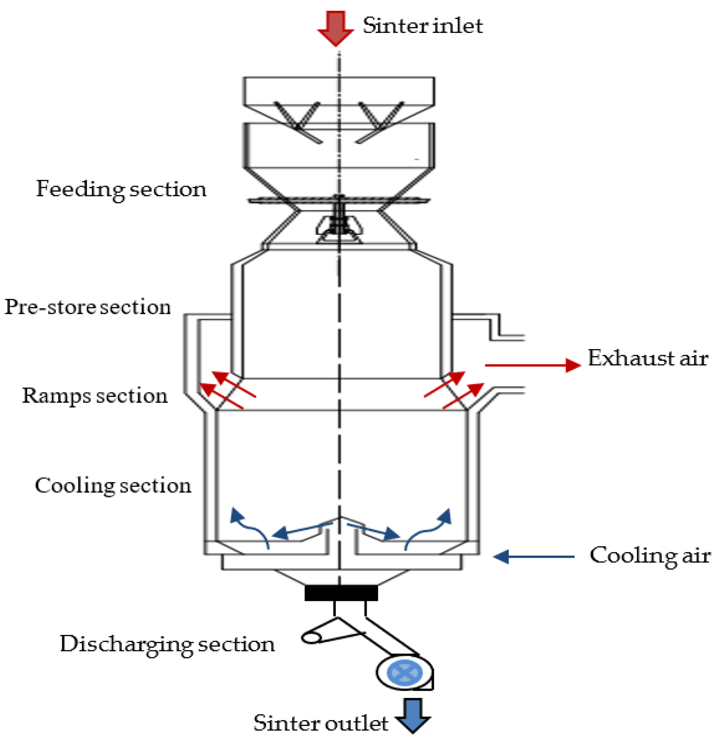
3.1. Physical Model
3.2. Mathematical Description
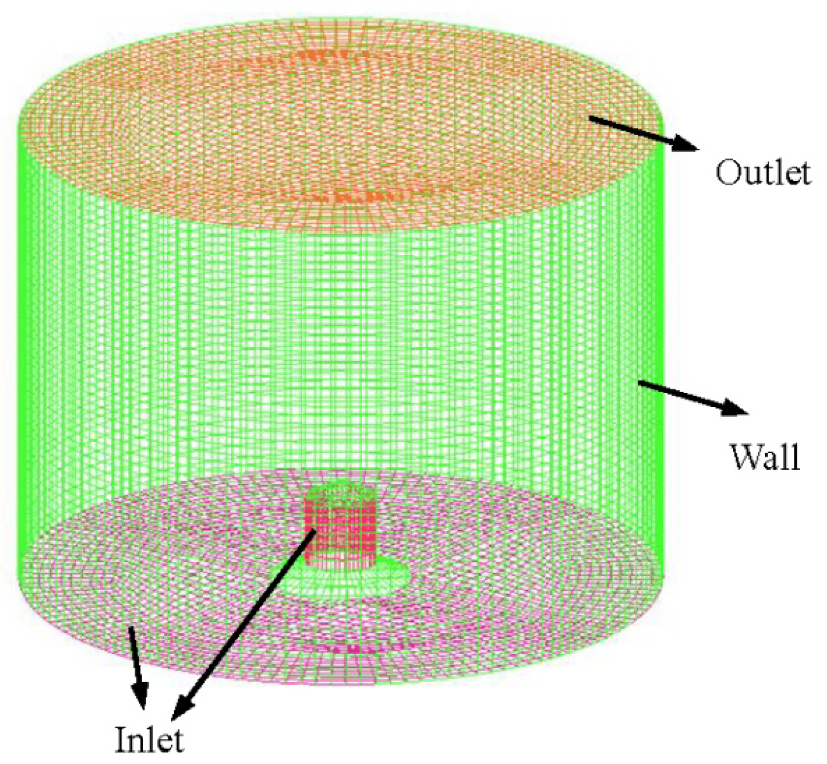
3.3. Grid Generation and Boundary Conditions
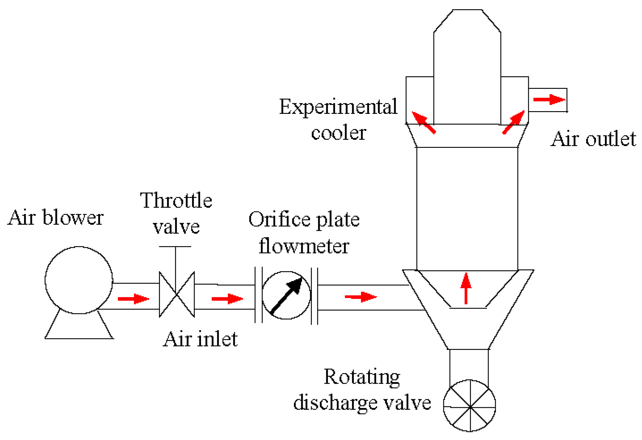
3.4. Model Verification
4. Results and Discussion
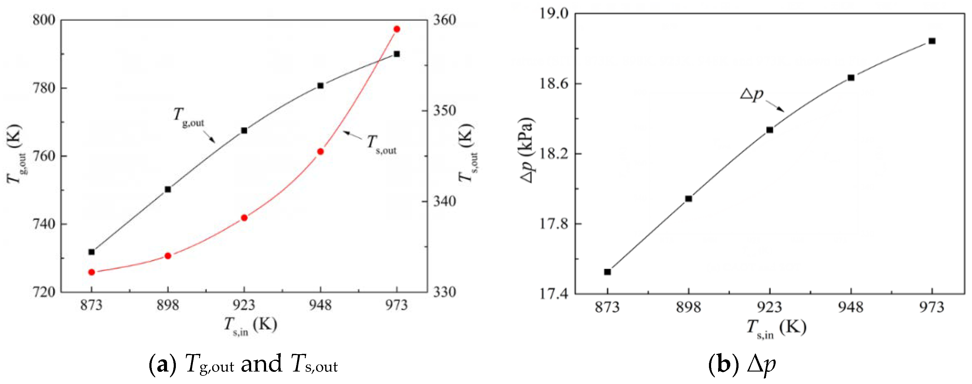
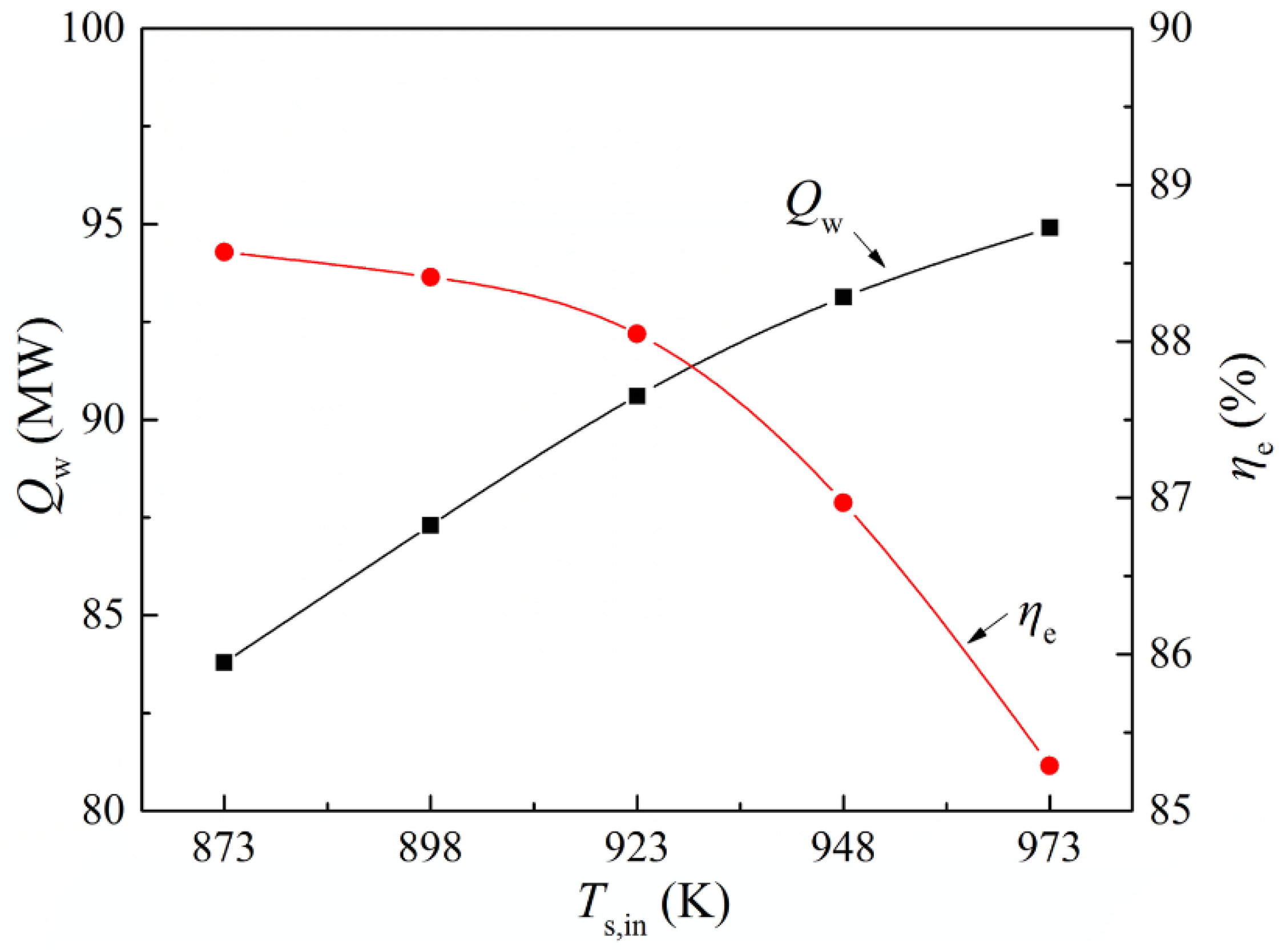
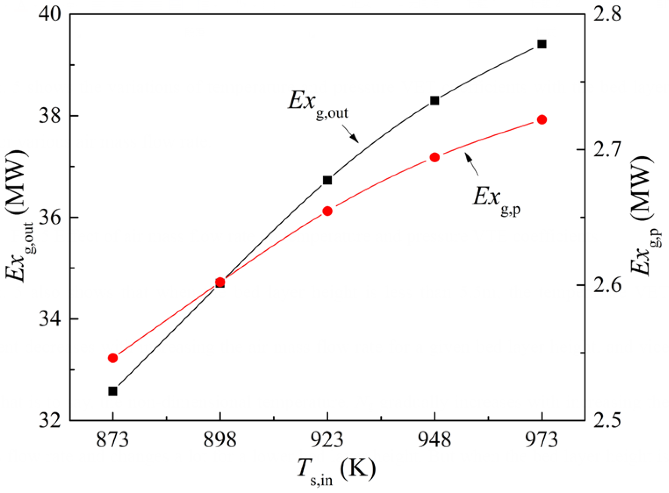
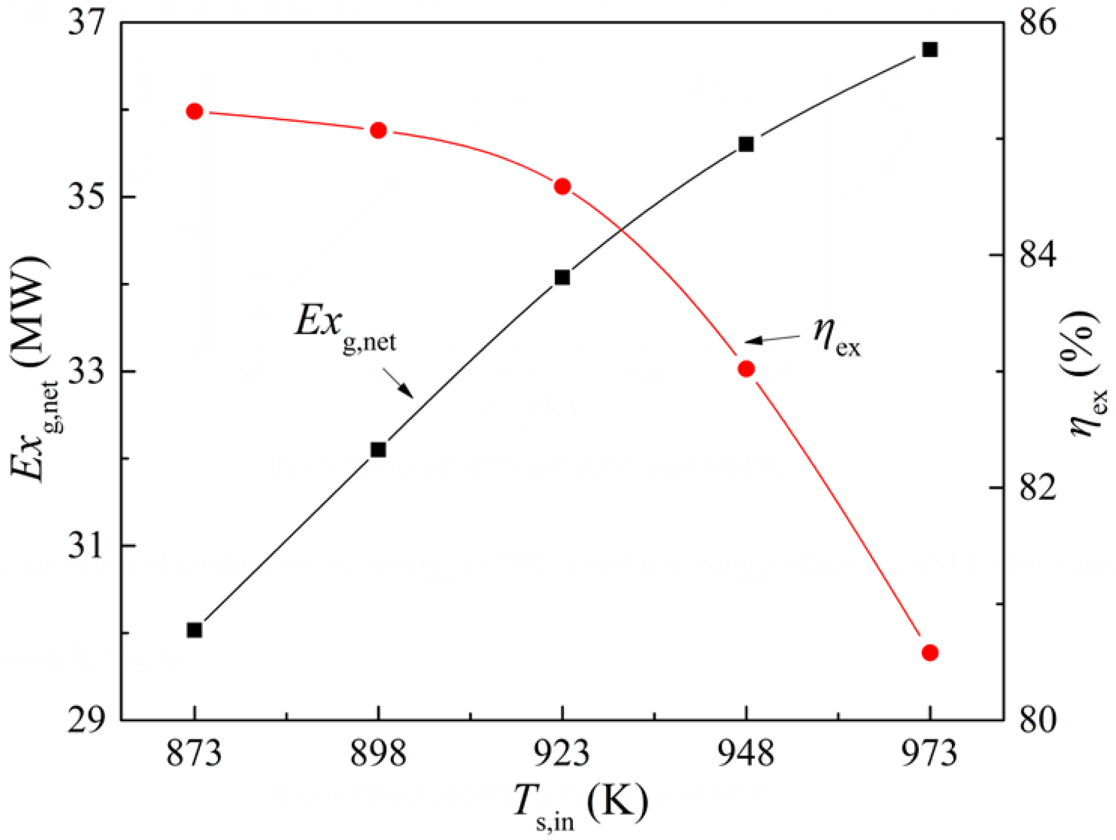
4.1. Effect of SIT
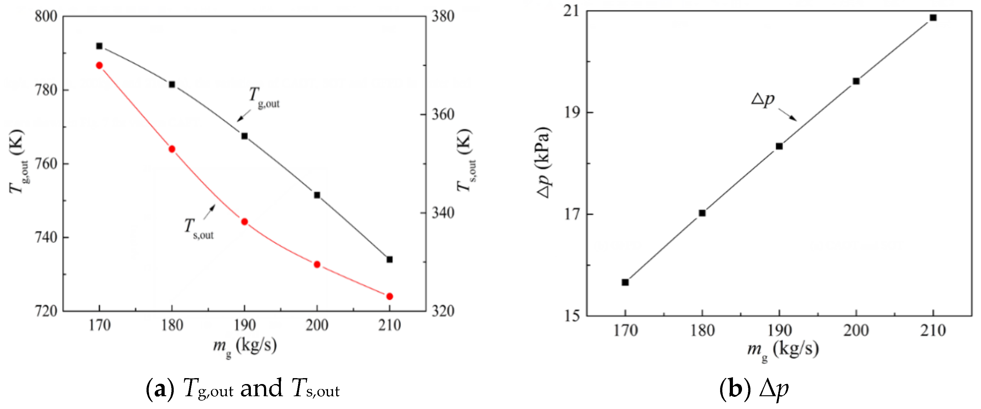
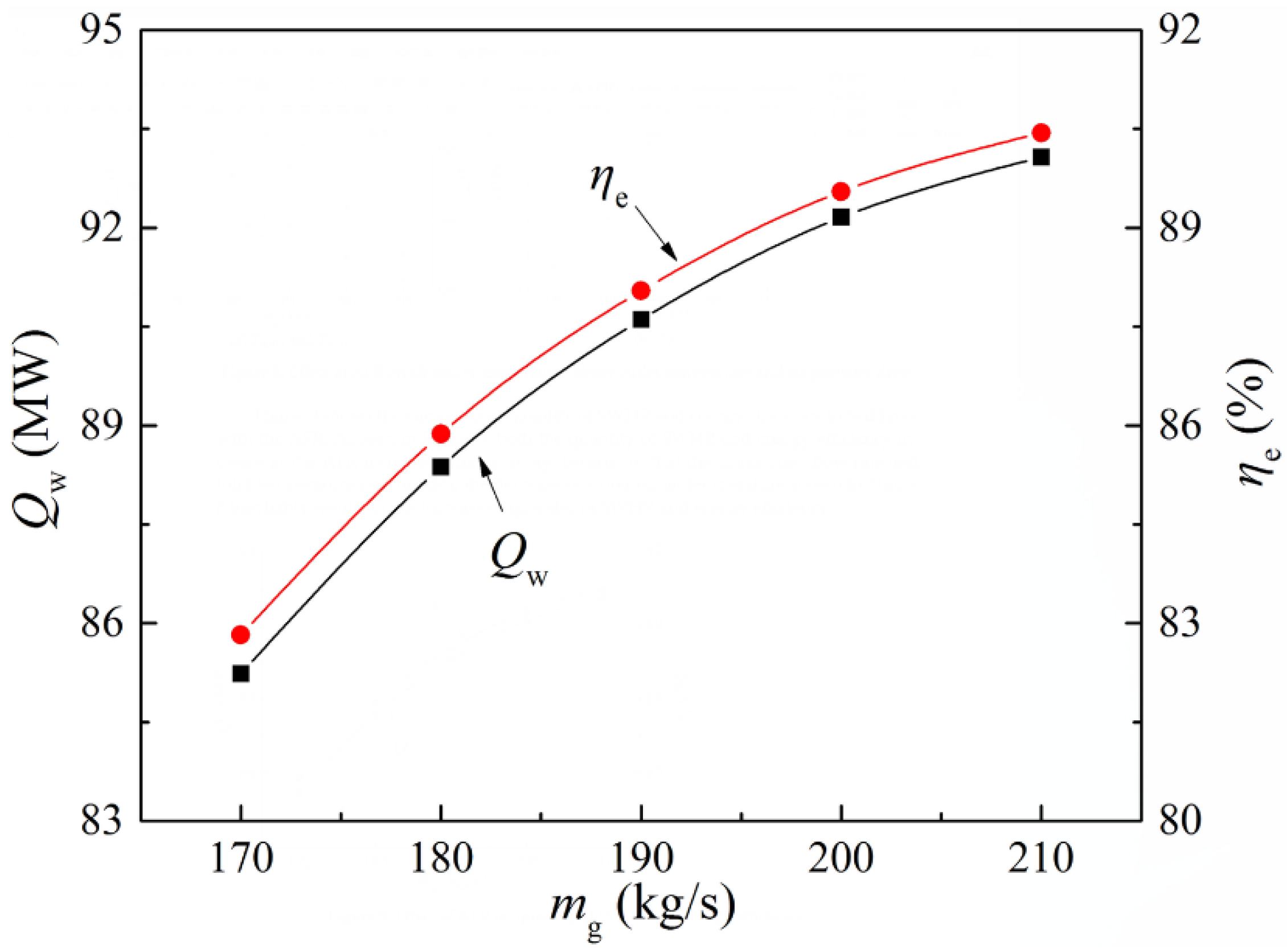
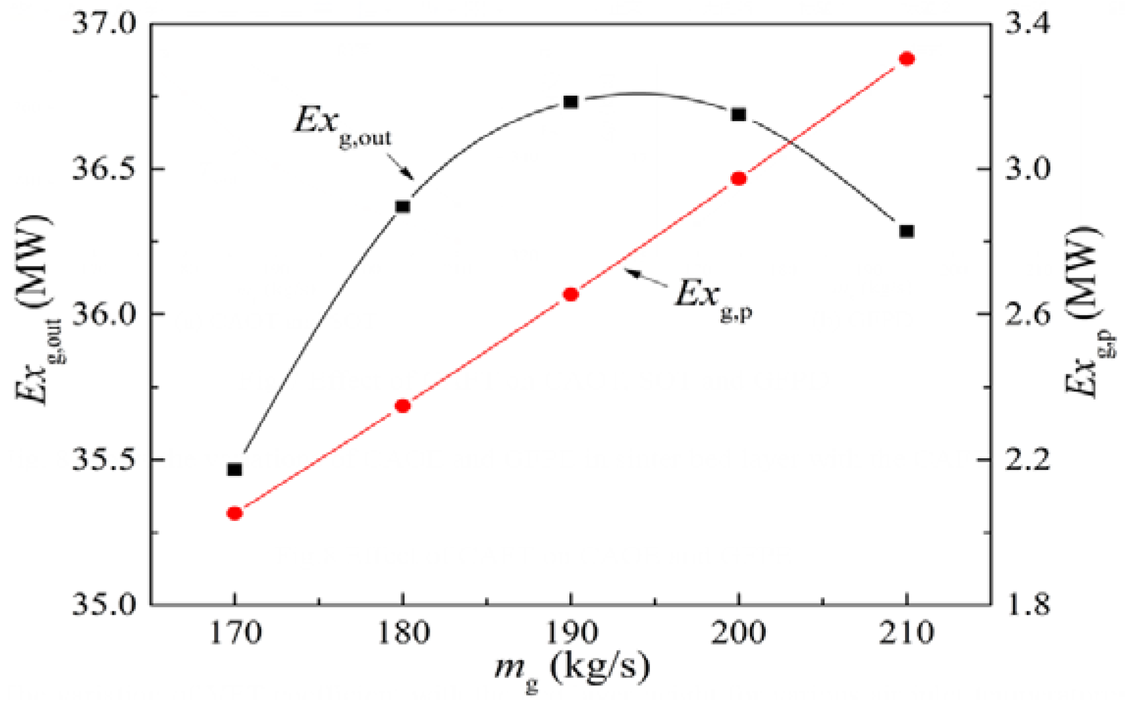
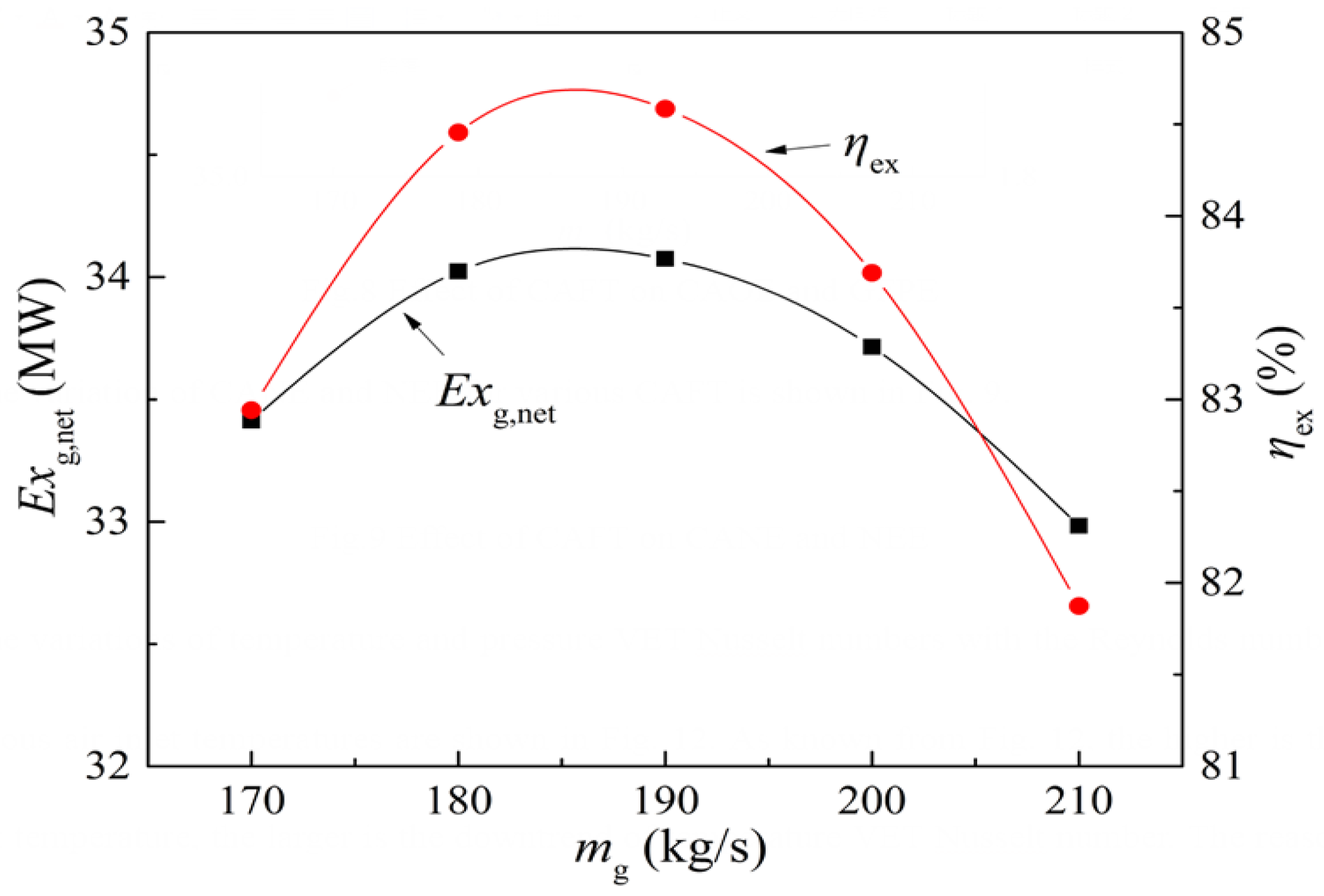
4.2. Effect of AFR
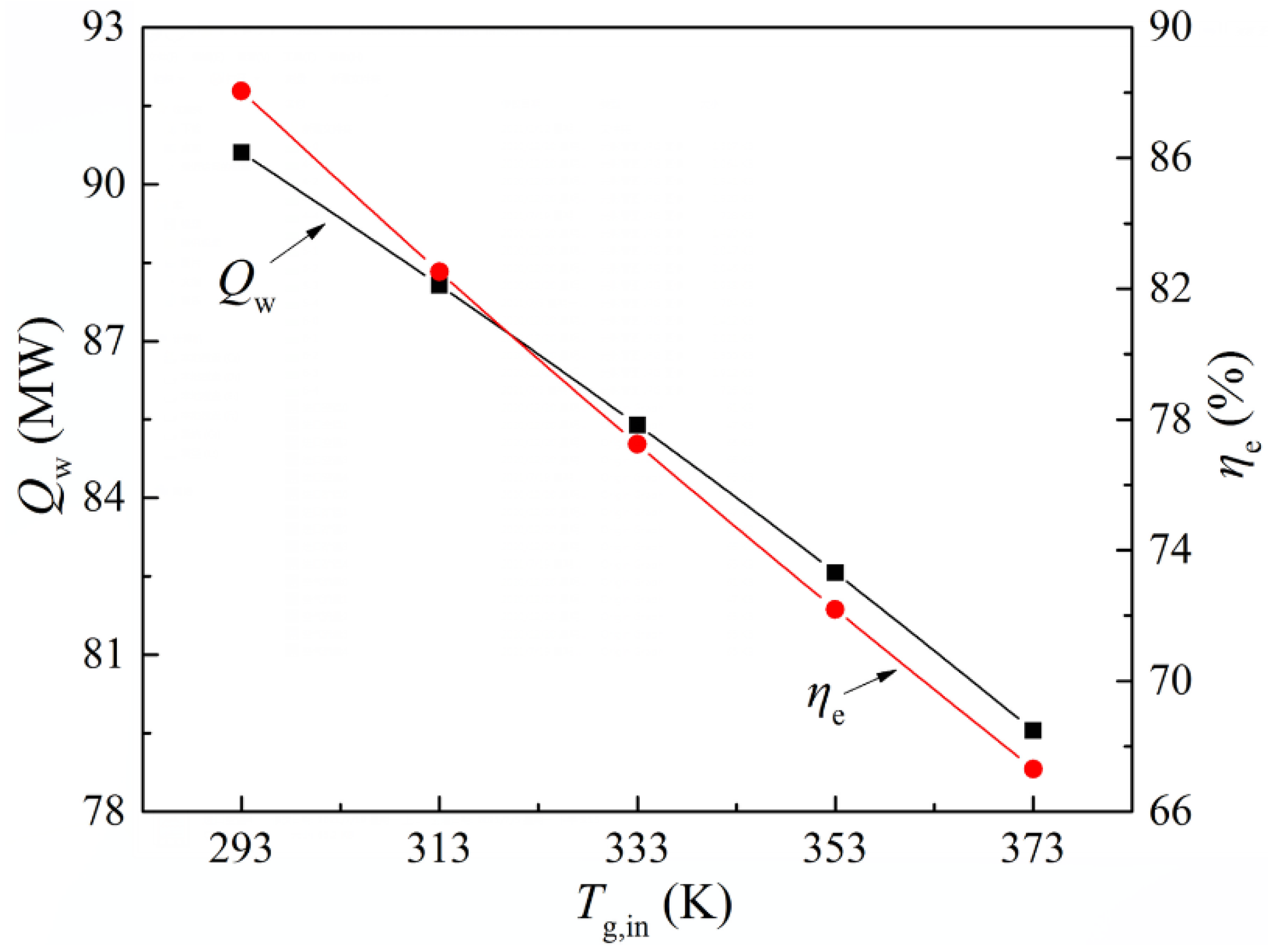
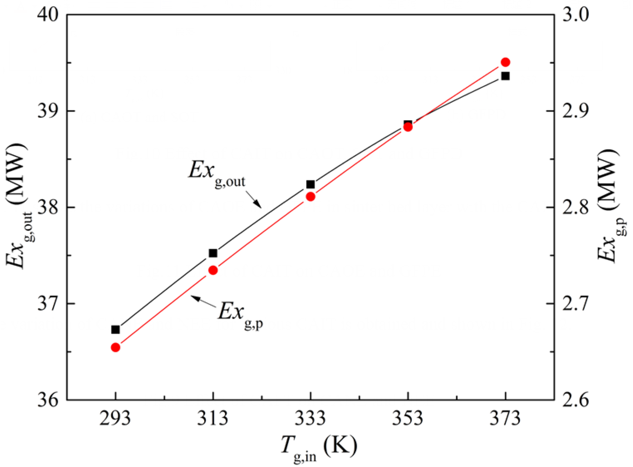
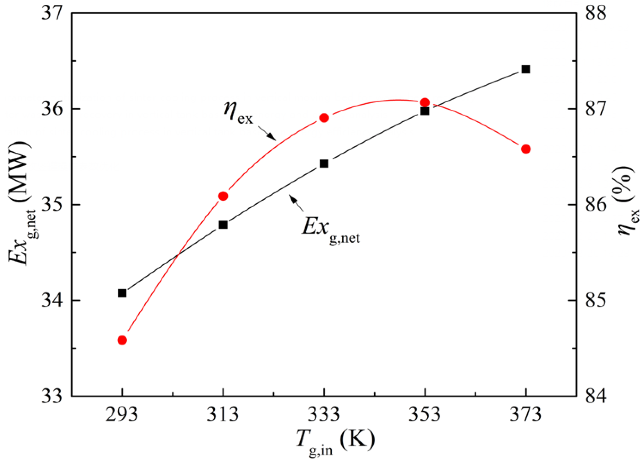
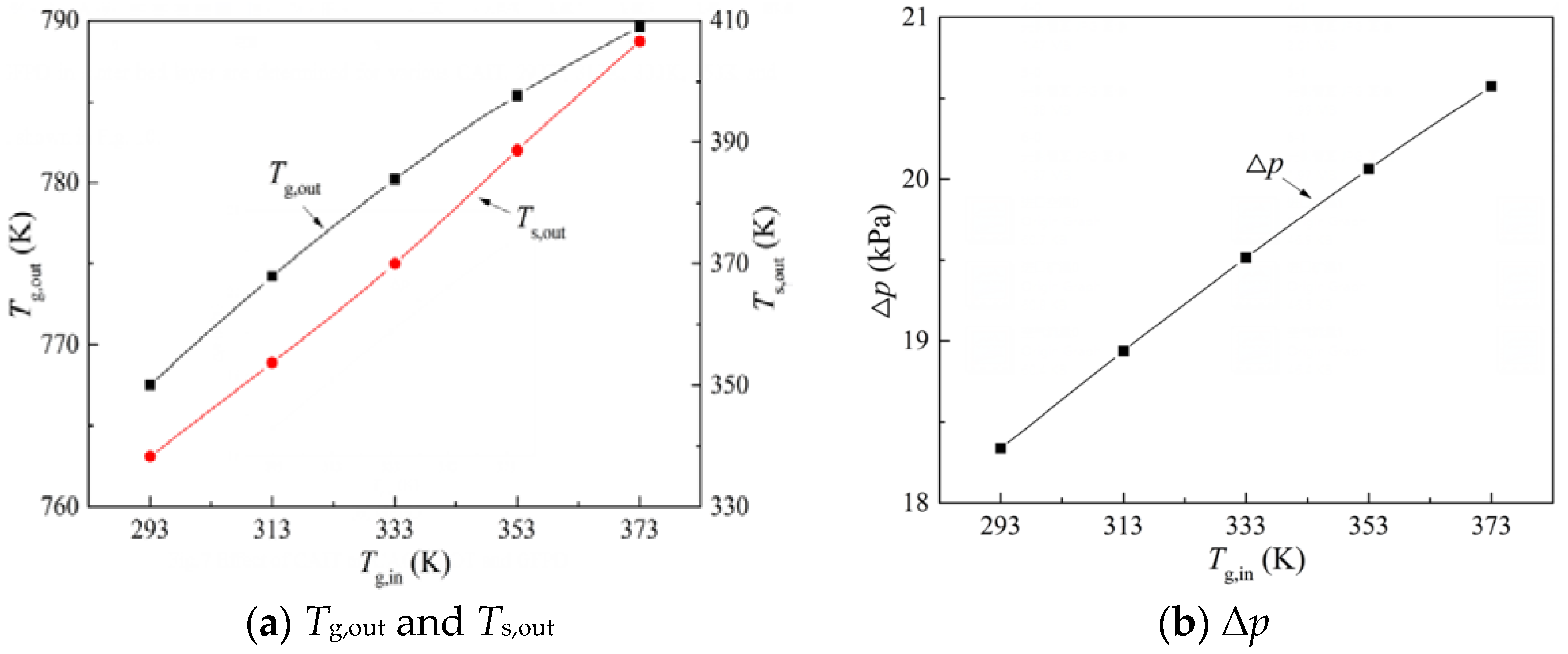
4.3. Effect of AIT
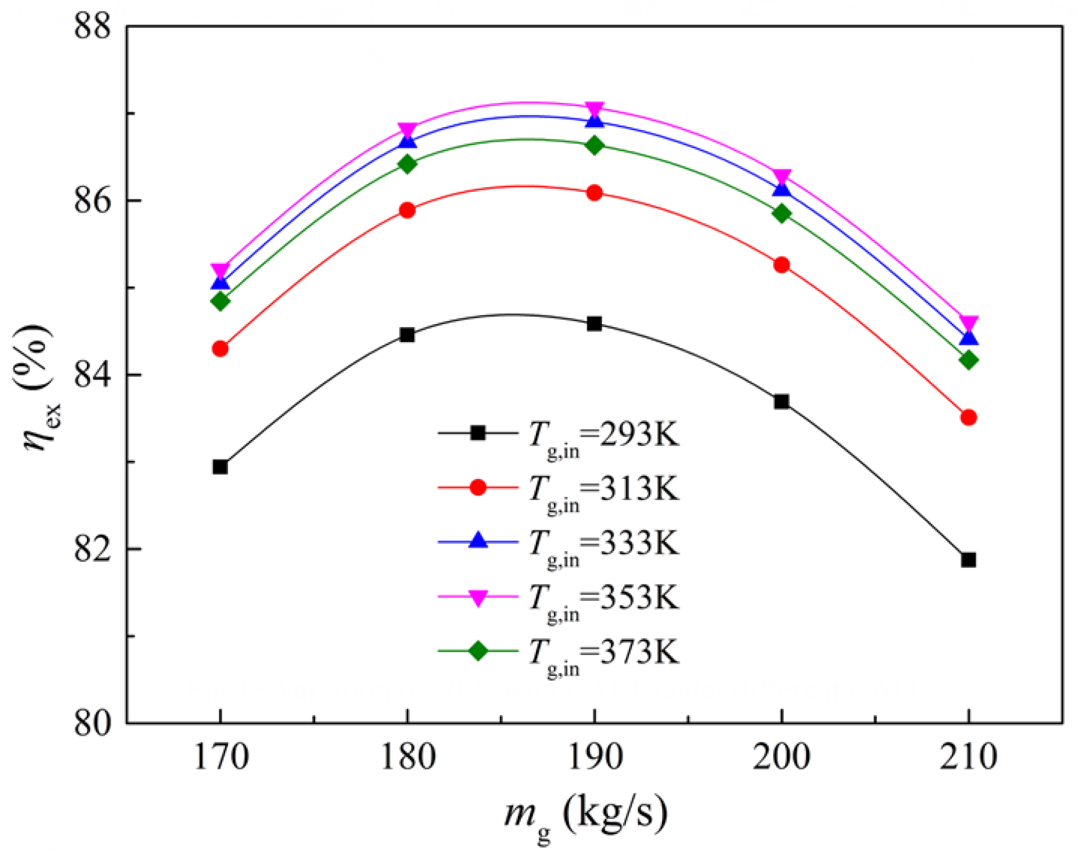
4.4. Optimization Analysis of Operational Parameter
5. Conclusions
Author Contributions
Funding
Institutional Review Board Statement
Informed Consent Statement
Data Availability Statement
Conflicts of Interest
Abbreviations
| 1/a | viscous resistance coefficient |
| c | specific heat (J/(kg·K)) |
| C2 | inertial resistance coefficient |
| D | inner diameter of cooling section (m) |
| dp | sinter equivalent diameter (m) |
| Exg,out | air outlet exergy (MW) |
| Exg,in | air inlet exergy (MW) |
| Exg,p | air pressure exergy (MW) |
| Exg,net | air net exergy (MW) |
| Exs,in | sinter inlet exergy (MW) |
| h | convective heat transfer coefficient (W/(m·K)) |
| m | mass flow rate (kg/s) |
| Nu | heat transfer Nusselt number |
| p0 | ambient pressure (N/m2) |
| pin | air inlet pressure (N/m2) |
| Qw | quantity of sinter waste heat recovery (MW) |
| Qg,in | gas inlet energy (MW) |
| Qs,in | sinter inlet energy (MW) |
| Pr | Prandtl number |
| Rg | air constant (J/(kg·K)) |
| Re | Reynolds number |
| T | temperature (K) |
| T0 | ambient temperature (K) |
| u | superficial velocity (m/s) |
| AFR | air flow rate |
| AIT | air inlet temperature |
| SIT | sinter outlet temperature |
| SWHR | sinter waste heat recovery |
| Greek Symbols | |
| ε | bed voidage |
| λ | thermal conductivity (W/(m·K)) |
| μ | dynamic viscosity (kg/(m·s)) |
| μT | turbulent viscosity coefficient (kg/(m·s)) |
| ρ | density (kg/m3) |
| ηex | net exergy efficiency |
| Δp | air pressure drop (N/m2) |
| Subscripts | |
| 0 | external environment state |
| ex | exergy |
| g | air |
| in | inlet |
| out | outlet |
| p | pressure |
| s | sinter |
References
- Dong, H.; Ling, H.Y.; Zhang, H.H.; Cai, J.J.; Xu, C.B.; Zhou, J.W. Thermal test and analysis of sintering cooling process. Iron Steel 2011, 46, 93–98. [Google Scholar]
- Wang, X.D.; Tian, J.L.; Song, C.Y. Innovative practice technology and outlook in large iron and steel enterprise green manufacturing. Iron Steel 2018, 53, 1–9. [Google Scholar]
- Cheng, Z.L.; Guo, Z.G.; Tan, Z.T.; Yang, J.; Wang, Q.W. Waste heat recovery from high-temperature solid granular materials: Energy challenges and opportunities. Renew. Sust. Energ. Rev. 2019, 116, 109428. [Google Scholar] [CrossRef]
- Cheng, Z.L.; Tan, Z.T.; Guo, Z.G.; Yang, J.; Wang, Q.W. Recent progress in sustainable and energy-efficient technologies for sinter production in the iron and steel industry. Renew. Sust. Energ. Rev. 2020, 131, 110034. [Google Scholar] [CrossRef]
- Dong, H.; Zhao, Y.; Cai, J.J.; Zhou, J.W.; Ma, G.Y. On the air leakage problem in sintering cooling system. Iron Steel 2012, 47, 95–99. [Google Scholar]
- Cai, J.J.; Dong, H. Method and Device of Sinter Waste Heat Recovery and Utilization with Vertical Tank. Chinese Patent 200910187381.8, 5 January 2011. [Google Scholar]
- Zhang, X.H.; Chen, Z.; Zhang, J.Y.; Ding, P.X.; Zhou, J.M. Simulation and optimization of waste heat recovery in sinter cooling process. Appl. Therm. Eng. 2013, 54, 7–15. [Google Scholar] [CrossRef]
- Liu, Y.; Yang, J.; Cheng, Z.L.; Wang, J.; Wang, Q.W. Cost Benefits Analysis for Waste Heat Utilization in Sinter Cooling Bed. Chem. Eng. Trans. 2014, 39, 841–846. [Google Scholar]
- Liu, Y.; Yang, J.; Wang, J.; Cheng, Z.L.; Wang, Q.W. Energy and exergy analysis for waste heat cascade utilization in sinter cooling bed. Energy 2014, 67, 370–380. [Google Scholar] [CrossRef]
- Tian, W.Y.; Zhang, J.Y.; Dai, C.D.; Long, X.Y. Recovery of waste heat from sinter cooling process: Simulation and optimization. Ironmak. Steelmak. 2015, 42, 97–104. [Google Scholar] [CrossRef]
- Feng, H.J.; Chen, L.G.; Liu, X.; Xie, Z.H.; Sun, F.R. Constructal optimization of a sinter cooling process based on exergy output maximization. Appl. Therm. Eng. 2016, 96, 161–166. [Google Scholar] [CrossRef]
- Zhang, S.; Feng, J.S.; Dong, H. Simulation and optimization of thermal parameter of sinter annular cooler based on enthalpy exergy of heat carrier. CIESC J. 2017, 68, 4129–4136. [Google Scholar]
- Zhang, S.; Gao, J.Y.; Feng, J.S.; Dong, H. Simulation and optimization of heat recovery section of annular cooler based on enthalpy exergy of heat carrier. J. Cent. South Univ. (Sci. Technol.) 2018, 49, 2083–2090. [Google Scholar]
- Zhang, S.; Zhao, L.; Feng, J.S.; Luo, X.F.; Dong, H. Parameter optimization of gas–solid heat transfer process in sinter packed bed based on further exergy analysis. Chem. Eng. Res. Des. 2019, 146, 499–508. [Google Scholar] [CrossRef]
- Zhang, S.; Zhao, L.; Feng, J.S.; Dong, H. Effect of operating parameters on gas-solid exergy transfer performance in sinter annular cooler. Appl. Therm. Eng. 2020, 181, 115928. [Google Scholar] [CrossRef]
- Tian, W.Y.; Jiang, C.; Ni, B.Y.; Wu, Z.T.; Wang, Q.; Yang, L.F. Global sensitivity analysis and multi-objective optimization design of temperature field of sinter cooler based on energy value. Appl. Therm. Eng. 2018, 143, 759–766. [Google Scholar] [CrossRef]
- Tian, W.Y.; Ni, B.Y.; Jiang, C.; Wu, Z.T. Uncertainty analysis and optimization of sinter cooling process for waste heat recovery. Appl. Therm. Eng. 2019, 150, 111–120. [Google Scholar] [CrossRef]
- Afridi, M.I.; Qasim, M.; Makinde, O.D. Entropy generation due to heat and mass transfer in a flow of dissipative elastic fluid through a porous medium. J. Heat Transfer. 2019, 141, 022002. [Google Scholar] [CrossRef]
- Makinde, O.D.; Eegunjobi, A.S. Entropy analysis of a variable viscosity MHD couette flow between two concentric pipes with convective cooling. Eng. Trans. 2020, 68, 317–334. [Google Scholar]
- Feng, J.S.; Dong, H.; Liu, J.Y.; Liang, K.; Gao, J.Y. Experimental study of gas flow characteristics in vertical tank for sinter waste heat recovery. Appl. Therm. Eng. 2015, 91, 73–79. [Google Scholar] [CrossRef]
- Feng, J.S.; Dong, H.; Gao, J.Y.; Liu, J.Y.; Liang, K. Exergy transfer characteristics of gas-solid heat transfer through sinter bed layer in vertical tank. Energy 2016, 111, 154–164. [Google Scholar] [CrossRef]
- Feng, J.S.; Dong, H.; Gao, J.Y.; Liu, J.Y.; Liang, K. Theoretical and experimental investigation on vertical tank technology for sinter waste heat recovery. J. Cent. South Univ. 2017, 24, 2281–2287. [Google Scholar] [CrossRef]
- Fu, Q.S. Thermodynamic Analysis Method of Energy System; Xi’an Jiaotong University Press: Xi’an, China, 2005. [Google Scholar]
- Feng, J.S.; Dong, H.; Zhao, Y. Numerical investigation of gas flow in vertical tank for recovering sinter waste heat. J. Northeast. Univ. (Nat. Sci.) 2015, 36, 660–664. [Google Scholar]
- Jang, J.Y.; Chiu, Y.W. 3-D Transient conjugated heat transfer and fluid flow analysis for the cooling process of sintered bed. Appl. Therm. Eng. 2009, 29, 2895–2903. [Google Scholar] [CrossRef]
- Lesage, F.; Midoux, N.; Latifi, M.A. New local measurements of hydrodynamics in porous media. Exp. Fluid 2004, 37, 257–262. [Google Scholar] [CrossRef]
- Yang, J.; Zeng, M.; Wang, Q.W.; Nakayama, A. Forced convection heat transfer enhancement by porous pin fins in rectangular channels. ASME J. Heat Transf. 2010, 132, 051702. [Google Scholar] [CrossRef]
- Wakao, N.; Funazkri, T. Effect of fluid dispersion coefficients on particle-to-fluid mass transfer coefficients in packed beds. Chem. Eng. Sci. 1978, 33, 1375–1384. [Google Scholar] [CrossRef]
- Feng, J.S. Study on Gas-Solid Heat Transfer Model in Vertical Tank for Recycling Sinter Waste Heat. Master’s Thesis, Northeastern University, Shenyang, China, 2014. [Google Scholar]
- Feng, J.S.; Dong, H.; Dong, H.D. Modification of Ergun’s correlation in vertical tank for sinter waste heat recovery. Powder Technol. 2015, 280, 89–93. [Google Scholar] [CrossRef]
- Kye, S.H.; Jae, H.J.; Won, K.L. Fixed-bed adsorption for bulk component system: Non-equilibrium non-isothermal and non-adiabatic model. Chem. Eng. Sci. 1995, 50, 813–825. [Google Scholar]
- Feng, J.S.; Dong, H.; Gao, J.Y.; Liu, J.Y.; Liang, K. Experimental study of gas–solid overall heat transfer coefficient in vertical tank for sinter waste heat recovery. Appl. Therm. Eng. 2016, 95, 136–142. [Google Scholar] [CrossRef]
- Su, J.W.; Gu, Z.L.; Chen, C.G.; Xu, X.Y. A two-layer mesh method for discrete element simulation of gas-particle systems with arbitrarily polyhedral mesh. Int. J. Num. Meth. Eng. 2015, 103, 759–780. [Google Scholar] [CrossRef]
- Kamiński, M.; Carey, G.F. Stochastic perturbation-based finite element approach to fluid flow problems. Int. J. Numer. Methods H. 2005, 15, 671–697. [Google Scholar] [CrossRef]
- Feng, J.S.; Dong, H.; Gao, J.Y.; Liu, J.Y.; Liang, K. Numerical investigation of gas-solid heat transfer process in vertical tank for sinter waste heat recovery. Appl. Therm. Eng. 2016, 107, 135–143. [Google Scholar] [CrossRef] [Green Version]
- Tian, F.Y.; Huang, L.F.; Fan, L.W.; Weng, Y.K.; Ying, X.Y.; Yu, Z.T.; Cen, K.F. A comprehensive characterization on the structural and thermo-physical properties of sintered ore particles toward waste heat recovery applications. Appl. Therm. Eng. 2015, 90, 1007–1014. [Google Scholar] [CrossRef]
- Feng, J.S.; Zhang, S.; Dong, H.; Pei, G. Effect of gas inlet parameters on exergy transfer performance of sinter cooling process in vertical moving bed. Appl. Therm. Eng. 2019, 152, 126–134. [Google Scholar] [CrossRef]


| Parameters | Values |
|---|---|
| dp (m) | 0.035 |
| cs (J/(kg·K)) | 337.03 (Ts-273)0.152 |
| λs (w/(m·K)) | 2.87 |
| ρs (kg/m3) | 3400 |
| ε | 0.41 |
| T0 (K) | 293 |
| p0 (Pa) | 101,325 |
| Cases | SIT (°C) | AFR (m3/h) | Sinter Flow Rate (kg/h) | AIT (°C) | Air Outlet Temperature | ||
|---|---|---|---|---|---|---|---|
| Measurement Value (°C) | Simulation Value (°C) | Deviation (%) | |||||
| 1 | 769.2 | 2127 | 2520 | 20 | 504.5 | 481.6 | −4.56 |
| 2 | 873.6 | 1723 | 2160 | 20 | 631.3 | 594.5 | −5.83 |
| 3 | 720.9 | 1684 | 2160 | 20 | 502.4 | 478.6 | −4.74 |
| 4 | 732.7 | 1545 | 1800 | 20 | 477.9 | 454.2 | −4.96 |
| 5 | 781.4 | 1499 | 1800 | 20 | 543.1 | 518.3 | −4.57 |
| Levels | Ts,in (K) | mg (kg/s) | Tg,in (K) |
|---|---|---|---|
| 1 | 873 | 170 | 293 |
| 2 | 898 | 180 | 313 |
| 3 | 923 | 190 | 333 |
| 4 | 948 | 200 | 353 |
| 5 | 973 | 210 | 373 |
| Levels | mg (kg/s) | Tg,in (K) |
|---|---|---|
| 1 | 170 | 293 |
| 2 | 180 | 313 |
| 3 | 190 | 333 |
| 4 | 200 | 353 |
| 5 | 210 | 373 |
| Conditions | Parameter Setting | Tg,out (K) | Δp (kPa) | Exg,net (MW) | ηex (%) | |
|---|---|---|---|---|---|---|
| Tg,in (K) | mg (kg/s) | |||||
| 1 | 293 | 170 | 791.9 | 15.66 | 33.41 | 82.94 |
| 2 | 293 | 180 | 781.5 | 17.02 | 34.02 | 84.46 |
| 3 | 293 | 190 | 767.4 | 18.34 | 34.07 | 84.58 |
| 4 | 293 | 200 | 751.5 | 19.62 | 33.71 | 83.69 |
| 5 | 293 | 210 | 734.1 | 20.86 | 32.98 | 81.87 |
| 6 | 313 | 170 | 798.4 | 16.16 | 34.05 | 84.3 |
| 7 | 313 | 180 | 788.1 | 17.57 | 34.7 | 85.89 |
| 8 | 313 | 190 | 774.2 | 18.94 | 34.79 | 86.08 |
| 9 | 313 | 200 | 758.3 | 20.27 | 34.46 | 85.26 |
| 10 | 313 | 210 | 740.9 | 21.58 | 33.76 | 83.51 |
| 11 | 333 | 170 | 804.2 | 16.63 | 34.62 | 85.05 |
| 12 | 333 | 180 | 794 | 18.09 | 35.31 | 86.67 |
| 13 | 333 | 190 | 780.2 | 19.51 | 35.43 | 86.9 |
| 14 | 333 | 200 | 764.4 | 20.91 | 35.13 | 86.12 |
| 15 | 333 | 210 | 747.1 | 22.27 | 34.45 | 84.41 |
| 16 | 353 | 170 | 809.2 | 17.08 | 35.12 | 85.21 |
| 17 | 353 | 180 | 799.1 | 18.59 | 35.83 | 86.82 |
| 18 | 353 | 190 | 785.4 | 20.06 | 35.97 | 87.06 |
| 19 | 353 | 200 | 769.7 | 21.52 | 35.7 | 86.29 |
| 20 | 353 | 210 | 752.5 | 22.94 | 35.05 | 84.61 |
| 21 | 373 | 170 | 813.4 | 17.49 | 35.52 | 84.85 |
| 22 | 373 | 180 | 803.4 | 19.05 | 36.26 | 86.42 |
| 23 | 373 | 190 | 789.8 | 20.58 | 36.43 | 86.63 |
| 24 | 373 | 200 | 774.2 | 22.09 | 36.18 | 85.85 |
| 25 | 373 | 210 | 757.1 | 23.57 | 35.56 | 84.17 |
Publisher’s Note: MDPI stays neutral with regard to jurisdictional claims in published maps and institutional affiliations. |
© 2021 by the authors. Licensee MDPI, Basel, Switzerland. This article is an open access article distributed under the terms and conditions of the Creative Commons Attribution (CC BY) license (https://creativecommons.org/licenses/by/4.0/).
Share and Cite
Cheng, Z.; Wang, H.; Feng, J.; Xia, Y.; Dong, H. Energy and Exergy Efficiency Analysis of Fluid Flow and Heat Transfer in Sinter Vertical Cooler. Energies 2021, 14, 4522. https://doi.org/10.3390/en14154522
Cheng Z, Wang H, Feng J, Xia Y, Dong H. Energy and Exergy Efficiency Analysis of Fluid Flow and Heat Transfer in Sinter Vertical Cooler. Energies. 2021; 14(15):4522. https://doi.org/10.3390/en14154522
Chicago/Turabian StyleCheng, Zude, Haitao Wang, Junsheng Feng, Yongfang Xia, and Hui Dong. 2021. "Energy and Exergy Efficiency Analysis of Fluid Flow and Heat Transfer in Sinter Vertical Cooler" Energies 14, no. 15: 4522. https://doi.org/10.3390/en14154522
APA StyleCheng, Z., Wang, H., Feng, J., Xia, Y., & Dong, H. (2021). Energy and Exergy Efficiency Analysis of Fluid Flow and Heat Transfer in Sinter Vertical Cooler. Energies, 14(15), 4522. https://doi.org/10.3390/en14154522