1. Introduction
Regardless of offering several advantages such as high torque density, power density, efficiency, and power factor, permanent magnet (PM) machines are getting less consideration these days [
1,
2,
3,
4,
5,
6,
7] due to the increasing cost of rare-earth metals required to build PM machines. Besides the high cost, the extraction of rare-earth metals to attain continuous supply for the industries manufacturing PM electrical machines has also raised environmental concerns. This has motivated researchers to explore other options in the field of electrical machines which either require less magnets, as in the case of PM-assisted synchronous reluctance machines, or that require no magnet, such as WRSMs [
8,
9,
10].
In a customary WRSM, the rotor field excitation mechanism either requires brushes and slip rings or supplementary exciters to provide DC to the rotor winding. In the case of brushes and slip rings, the machine system requires maintenance due to the wearing of brushes, which increases its maintenance cost. On the other hand, the machine systems employing exciters for the rotor field excitation mechanism becomes expensive and bulky [
10,
11].
In recent years, several ideas related to the brushless and exciter-less topologies of WRSMs have been proposed. These ideas are based on a principle that generates spatial- and time-harmonics in the airgap.
In [
12,
13,
14,
15,
16], higher harmonics were generated in the airgap through input armature currents. These higher harmonics were utilized to produce a harmonic current in the harmonic winding which was later rectified to provide DC to the field winding of the rotor to attain brushless and exciter-less operation for WRSMs. A fractional-slot-concentrated winding (FSCW) was employed to generate the 5th and 13th-harmonic for a 10-pole machine in [
12]. The 5th-harmonic was employed to produce the main stator field, while the 13th-harmonic was utilized to energize the rotor field winding using the combination of harmonic winding and rectifier. A brushless WRSM (BL-WRSM) topology established on the principle of spatial-harmonic field-excitation technique was suggested in [
14]. This topology requires a high frequency, single-phase current or a DC component for the three-phase armature winding which is based on an open-winding configuration. The high frequency, single-phase or DC component produces a 3rd-harmonic MMF component in the airgap which was utilized to induce a harmonic current in the harmonic winding. The induced harmonic current was rectified to energize the rotor main field winding for brushless operation. In [
15], the brushless operation for WRSMs was attained by generating the 3rd-harmonic zero-sequence current for the armature winding by employing thyristor switches installed between each phase of the armature winding and the corresponding phase of the power supply. The installed thyristors were operating close to zero-crossing of each phase generating a zero-sequence, 3rd-harmonic MMF in the airgap. The generated MMF is utilized to produce a harmonic current of the harmonic winding. In [
16], a BL-WRSM topology built on the principle of injecting a distinctive current shape for the armature winding was proposed. This unique current shape is comprised of the fundamental and 3rd-harmonic current components. The fundamental was utilized to generate the main stator field, on the other hand the 3rd-harmonic was used to produce a harmonic current in the harmonic winding which was electrically connected to the rotor field winding via the rectifier for brushless operation.
In [
17], a BL-WRSM topology realized by utilizing a three-phase rectifier. The inverter provides the regular three-phase current to the stator winding in this topology, whereas a rectifier is employed whose output is connected to the neutral of the Y-connected armature winding. This generated an additional 3rd-harmonic MMF component in the airgap, which is then used to produce harmonic current in the harmonic winding to energize the rotor field winding for the brushless operation.
A novel brushless WRSM topology established on the principle of generating a supplementary sub-harmonic MMF component besides the fundamental MMF in the airgap was proposed in [
18]. For the validation of this topology, a 4-pole, 24-slot (4p24s) machine was utilized. The armature winding of the employed machine was divided into two symmetrical halves. Each half of the winding was having a distinct star-connection. This arrangement generated the fundamental as well as the sub-harmonic MMF components in the airgap. The fundamental MMF was utilized to generate the main stator field where the sub-harmonic MMF was applied to induce the harmonic current in the harmonic winding. The induced harmonic current was rectified to energize the rotor field winding for the brushless operation of WRSMs. As the proposed topology employs two halves of the armature winding installed at the opposite sections of the stator, the rotor of the machine experiences an unbalanced radial force. The magnitude of the unbalanced radial force generated for the rotor during the operation of the machine depends on the magnitude of difference of currents flowing through the two portions of the armature winding. Besides this, the proposed topology also possesses a higher torque ripple and lower average torque and efficiency due to the same reason. Although these issues were addressed to some extent by designing an 8-pole, 24-slot machine in [
19], the problems persist for a 4p24s machine in particular and brushless topologies based on sub-harmonic field excitation technique in general.
This paper proposes a new high-efficient BL-WRSM topology based on a sub-harmonic field excitation technique that involves two distinct windings: (1) main armature winding, and (2) additional armature winding installed in the stator slots. The main armature winding is a 4-pole winding and is supplied current from inverter-1, whereas the additional armature winding is a 2-pole winding and is supplied current from inverter-2, simultaneously. The main armature winding is delivered with a regular three-phase input current. On the other hand, the additional armature winding is provided a three-phase current of low magnitude as compared to the main armature winding. This generates an additional sub-harmonic component of MMF in the airgap beside the fundamental. The fundamental MMF is used to generate the main stator field. On the other hand, the additional sub-harmonic component of MMF is employed to induce a harmonic current in the specially designed rotor harmonic winding. The harmonic winding is electrically connected with the field winding via a rectifier. The induced harmonic current is rectified to give DC to the rotor field winding to develop the main rotor field to attain brushless operation. As the proposed BL-WRSM topology involves the circumferential distribution of the main and additional armature windings, the magnitude of the unbalanced radial force will be minimum as compared to the customary BL-WRSMs based on the sub-harmonic field excitation technique. In addition, the average output torque and efficiency of the proposed topology will be higher when compared to the customary BL-WRSM topology due to the higher number of slots used to house the main armature winding in the proposed topology. The structure and operation of the customary and proposed BL-WRSM topologies based on sub-harmonic field excitation techniques are discussed in subsequent sections.
2. Customary BL-WRSM Topology Based on Sub-Harmonic Field Excitation Technique
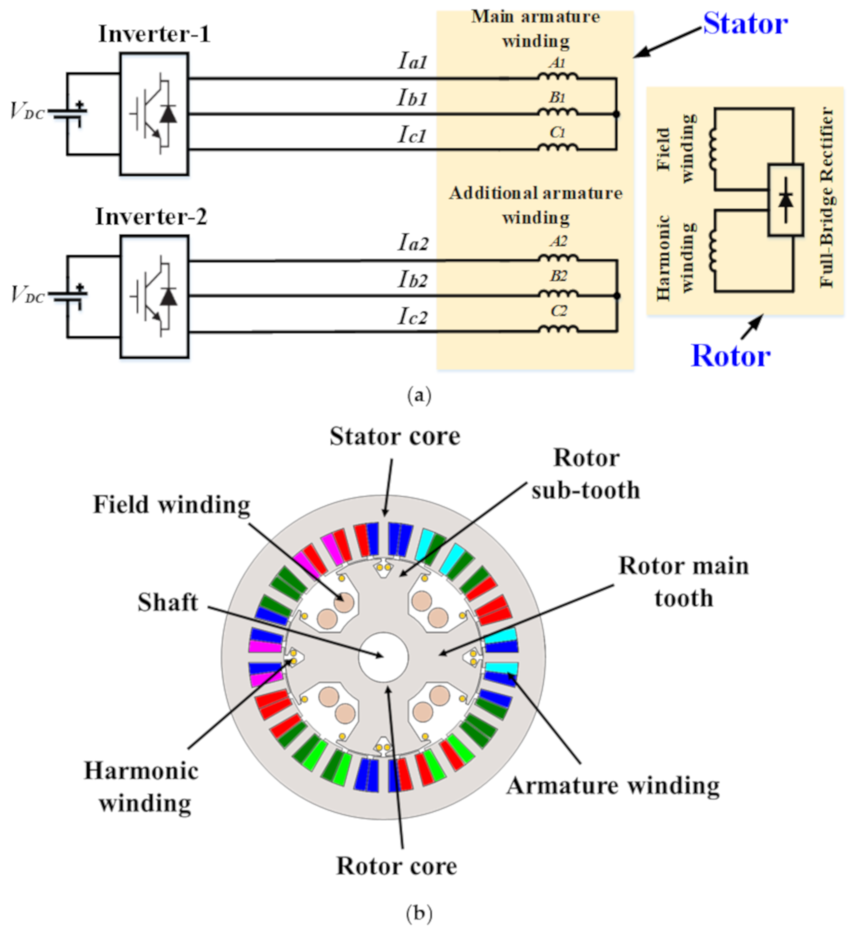
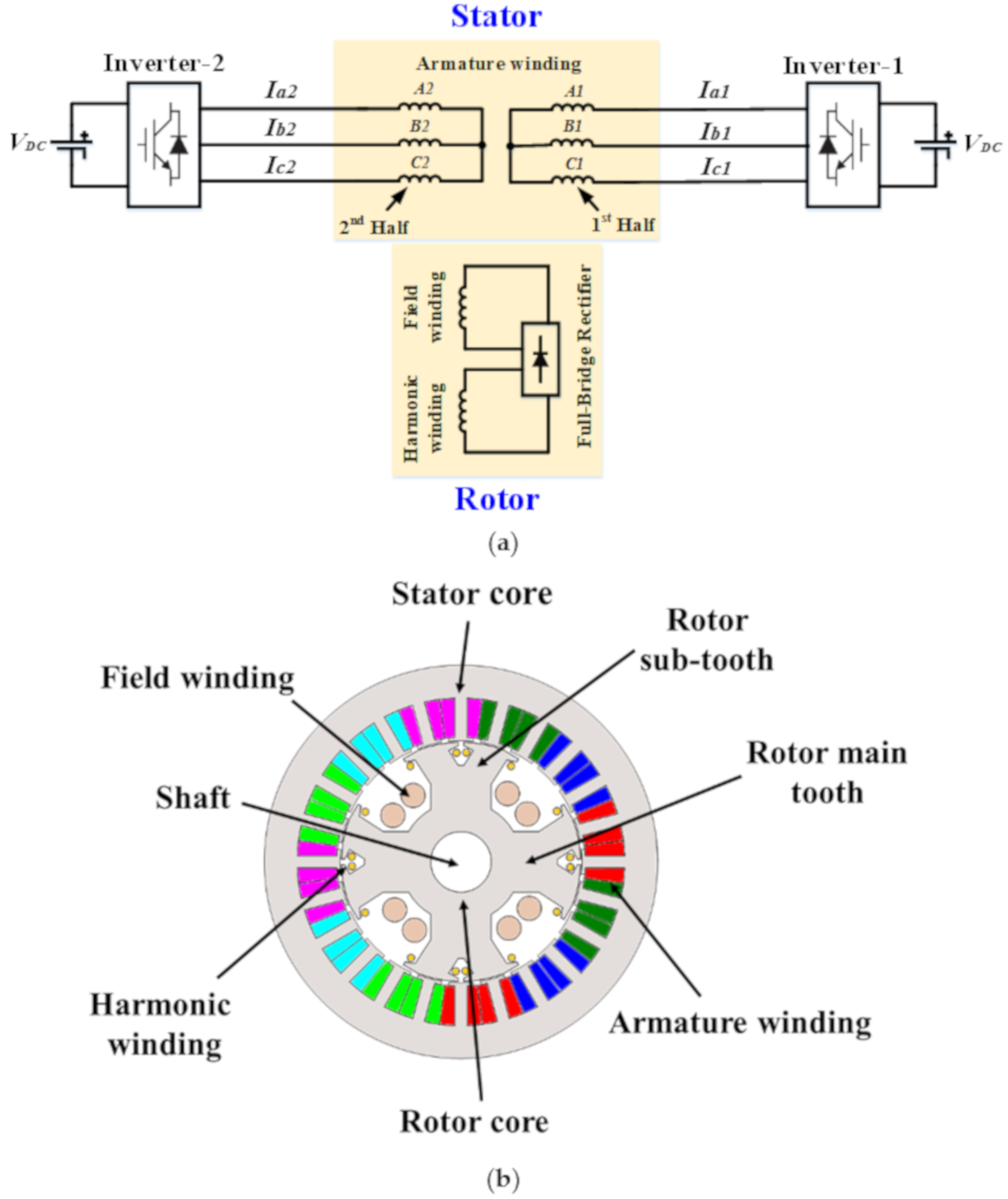
The customary brushless WRSM topology based on sub-harmonic field excitation technique is shown in
Figure 1a. It can be seen that the armature winding in the customary topology is divided into two halves, each of them is having a distinct star-connection. A 4p24s, double-layer armature winding is used for the employed machine as presented in
Figure 1b. The 1st half of the armature winding is based on a 2-pole, 12-slot (2p12s) winding configuration and is connected with inverter-1, whereas the 2nd half of the winding holds a similar winding configuration i.e., 2p12s, and is connected with inverter-2. Inverter-1 provides the regular three-phase currents (
Iabc1); however, inverter-2 provides the current (
Iabc2) of lower magnitude as compared to the magnitude of
Iabc1 i.e.,
Iabc2 <
Iabc1. The magnitude of input armature currents for inverter-1 and 2 are given as under:
where
I1 denotes the amplitude of the fundamental current,
ωe denotes the electrical angular frequency,
t represents the time, and
m is used to denote the ratio of the magnitude of inverter-1, and inverter-2 currents.
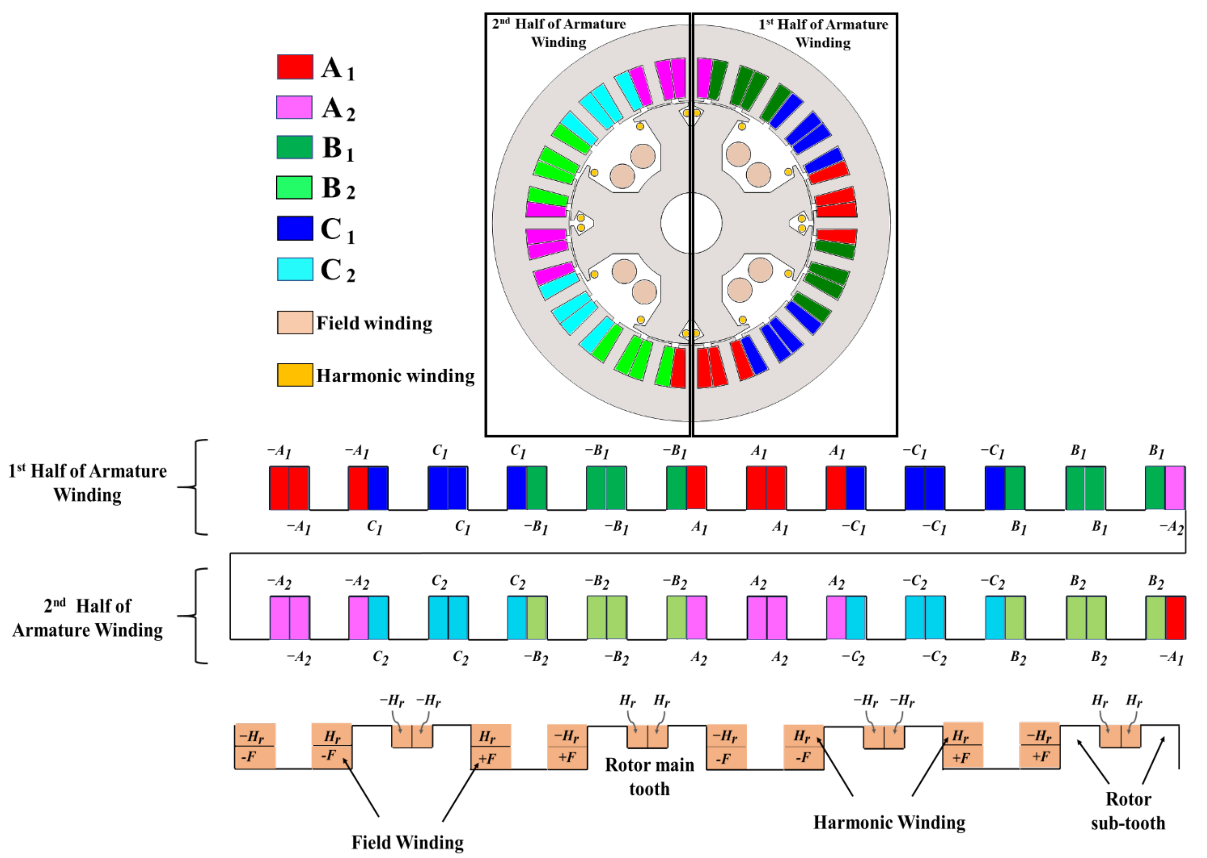
The rotor of the employed machine is designed to have four main teeth and eight sub-teeth to house a harmonic winding and a 4-pole rotor field winding. The armature and rotor winding configurations are illustrated in
Figure 2.
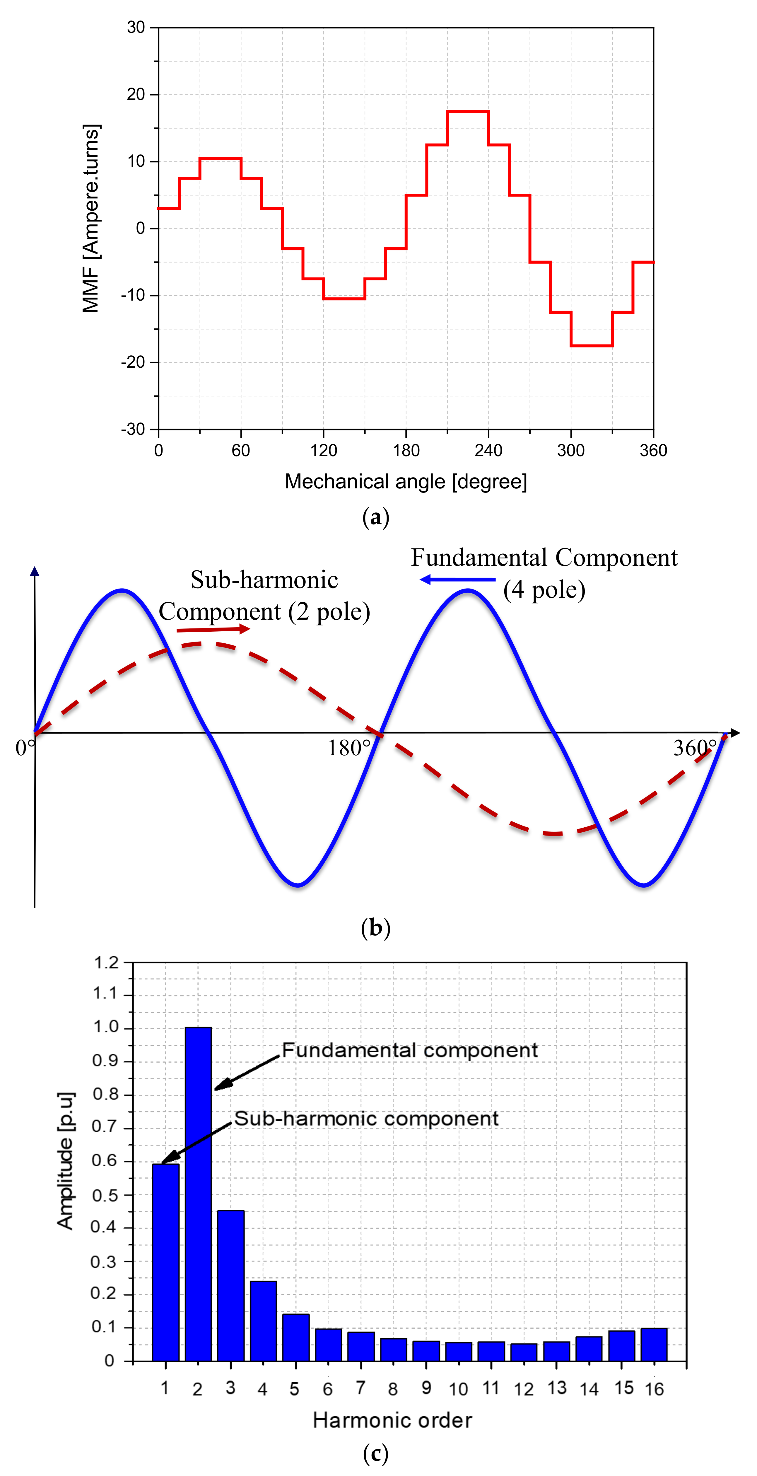
To understand the operation of the customary BL-WRSM topology, the first half of the armature winding is delivered with A three-phase input current of magnitude 1 (p.u), whereas the second half of the armature winding is provided 0.75 (p.u) current, simultaneously. This results in a MMF plot in the airgap as shown in
Figure 3a. The resultant MMF waveform for the airgap has two different portions. From 0 to 180 mechanical degrees, the MMF has the smaller maximum and minimum values due to the low magnitude of currents supplied to
A2,
B2, and
C2 windings. Similarly, as the magnitude of delivered three-phase currents to the windings
A1,
B1, and
C1 is high, the MMF is having larger minimum and maximum values from 180 to 360 mechanical degrees of the MMF plot. From the MMF plot, it can be seen that there are two dominant components (the fundamental component and the sub-harmonic component) of the MMF produced via the winding configurations discussed above. The fundamental component produces a 4-pole armature field having the frequency
ω, whereas the sub-harmonic component generates a 2-pole armature field with a frequency
ω/2 as shown in
Figure 3b. A fast Fourier transform (FFT) plot is obtained for the MMF of the customary BL-WRSM topology to show the magnitude of the fundamental and sub-harmonic components of the MMF. This FFT plot is shown in
Figure 3c, which illustrates that besides the fundamental, a sub-harmonic MMF component of amplitude 0.59 (p.u) is produced in the airgap. This amplitude of the sub-harmonic MMF component can be controlled by controlling the magnitudes of inverter-2 currents (
Iabc2) for the windings
A2,
B2, and
C2.
The rotating speed of the sub-harmonic field generated by the topology is different from the fundamental synchronous speed, which can be calculated using Equation (4).
where
ns(h) denotes the harmonic component’s rotating speed;
ns denotes the synchronous speed;
h is used to represent the harmonic number;
f is used to denote the supplied frequency, and
p is the number of poles.
Equation (4) suggests that the sub-harmonic component rotates at a speed that is double to synchronous speed. The difference in the speeds of the sub-harmonic and fundamental components produces the harmonic current in the rotor harmonic winding.
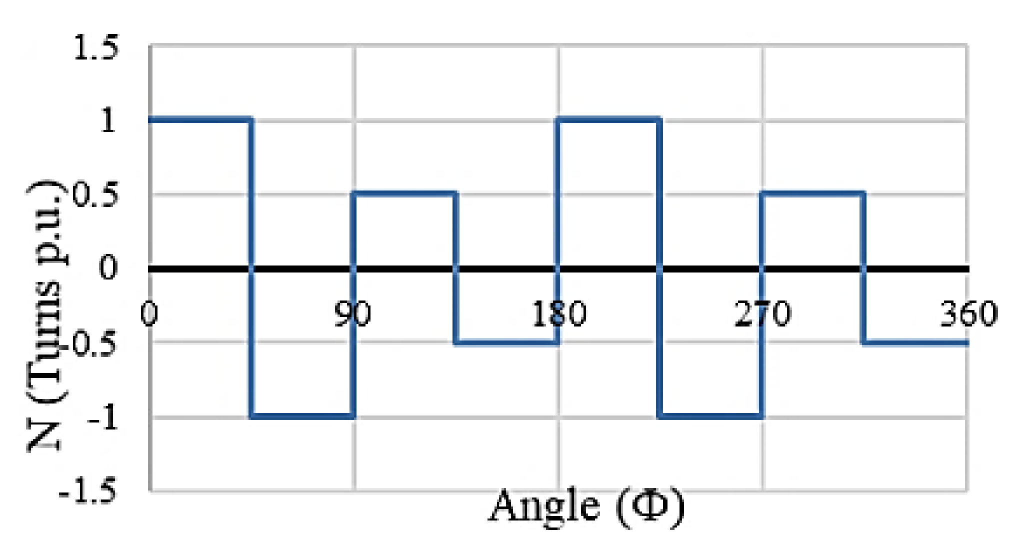
The combined winding functions (
NA(
ϕ) for both portions of phase
A) for the customary BL-WRSM topology considering a full pitched concentrated winding can be represented.
Similarly, for phase
B and
C, we have
Figure 4 shows the MMF waveform generated by unequal currents providing to the two portions of the full pitched concentrated winding of phase A. The airgap MMF is defined as:
By substituting the winding functions and the winding currents in the Equation (8), it becomes:
The second term in the above equation represents the sub-harmonic MMF component of the airgap MMF which is utilized to attain brushless excitation of the rotor.
The fundamental and sub-harmonic fields produced by the winding arrangement discussed before, rotate at different speeds due to their different frequencies. The fundamental component generates the main 4-pole armature field, whereas the sub-harmonic component is used to produce a harmonic current in the harmonic winding. The induced harmonic current is rectified to energize the 4-pole rotor field winding. The interaction of the 4-pole armature field and 4-pole rotor field generates torque.
3. Proposed BL-WRSM Topology Based on Sub-Harmonic Field Excitation Technique
The proposed brushless WRSM topology based on the sub-harmonic field excitation technique is shown in
Figure 5a. As shown in the figure, this topology involves two three-phase inverters i.e., inverter-1, and 2 connected to the main armature (
A1,
B1, and
C1) and additional armature (
A2,
B2, and
C2) windings. Inverter-1 gives the regular three-phase current (
Iabc1) to the main armature winding. However, inverter-2 delivers the low magnitude of input current (
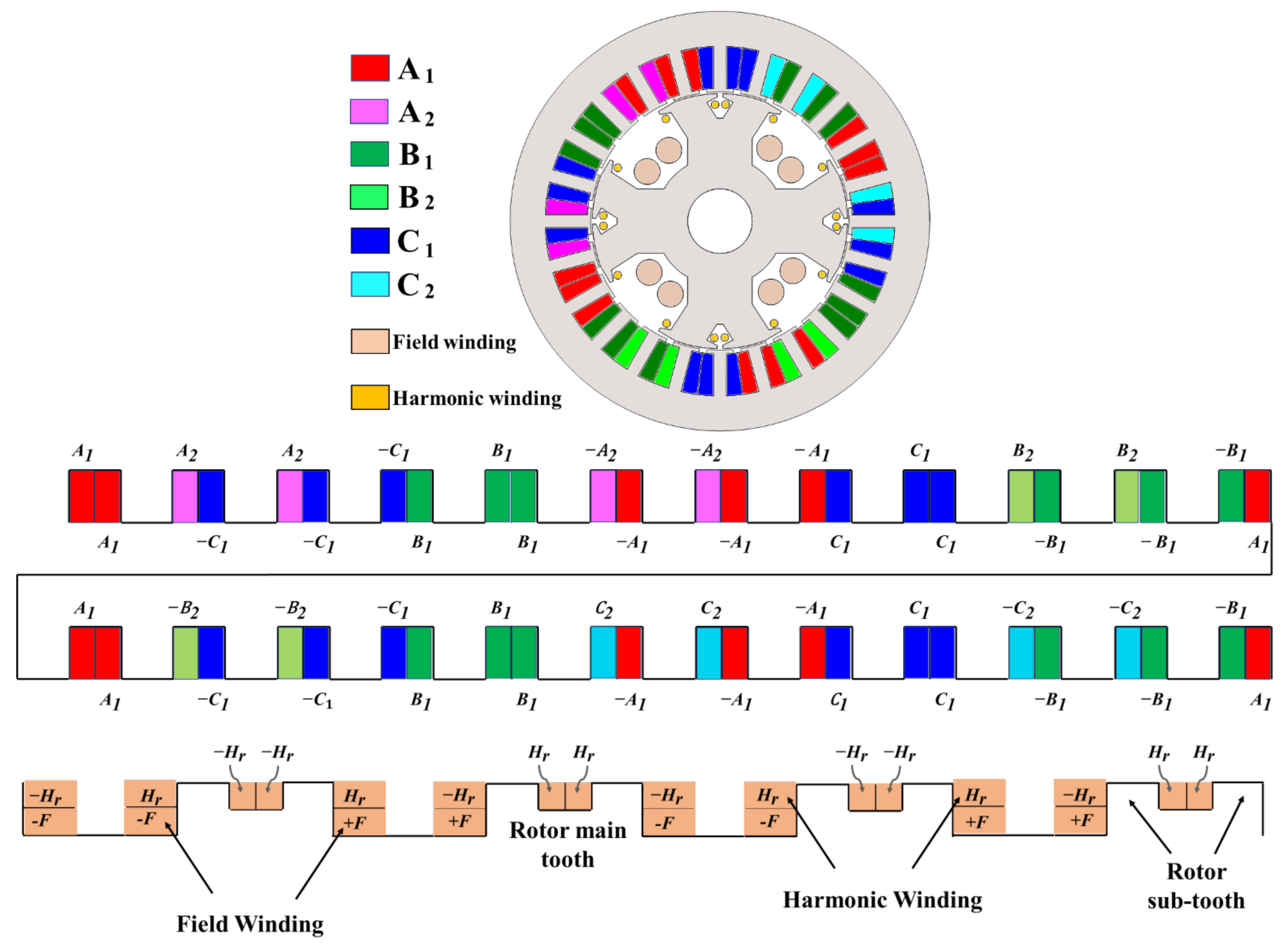
Iabc2) compared to the inverter-1 to the additional armature winding. The machine structure is presented in
Figure 5b, whereas the winding configuration for the employed machine is shown in
Figure 6. The main armature winding employs a 4p24s winding configuration. Out of these 24 slots, 12 slots are completely filled with the main armature winding, while the rest of the 12 slots are half-filled to hold the 2-pole additional armature winding. The structure of the rotor for the employed machine is kept the same as in the case of the customary BL-WRSM topology based on the sub-harmonic field-excitation technique.
Like the customary BL-WRSM topology, the main armature winding of the proposed topology is supplied with 1 (p.u) current i.e.,
Iabc1 = 1 (p.u), whereas the additional armature winding is delivered a current of magnitude 0.75 (p.u) i.e.,
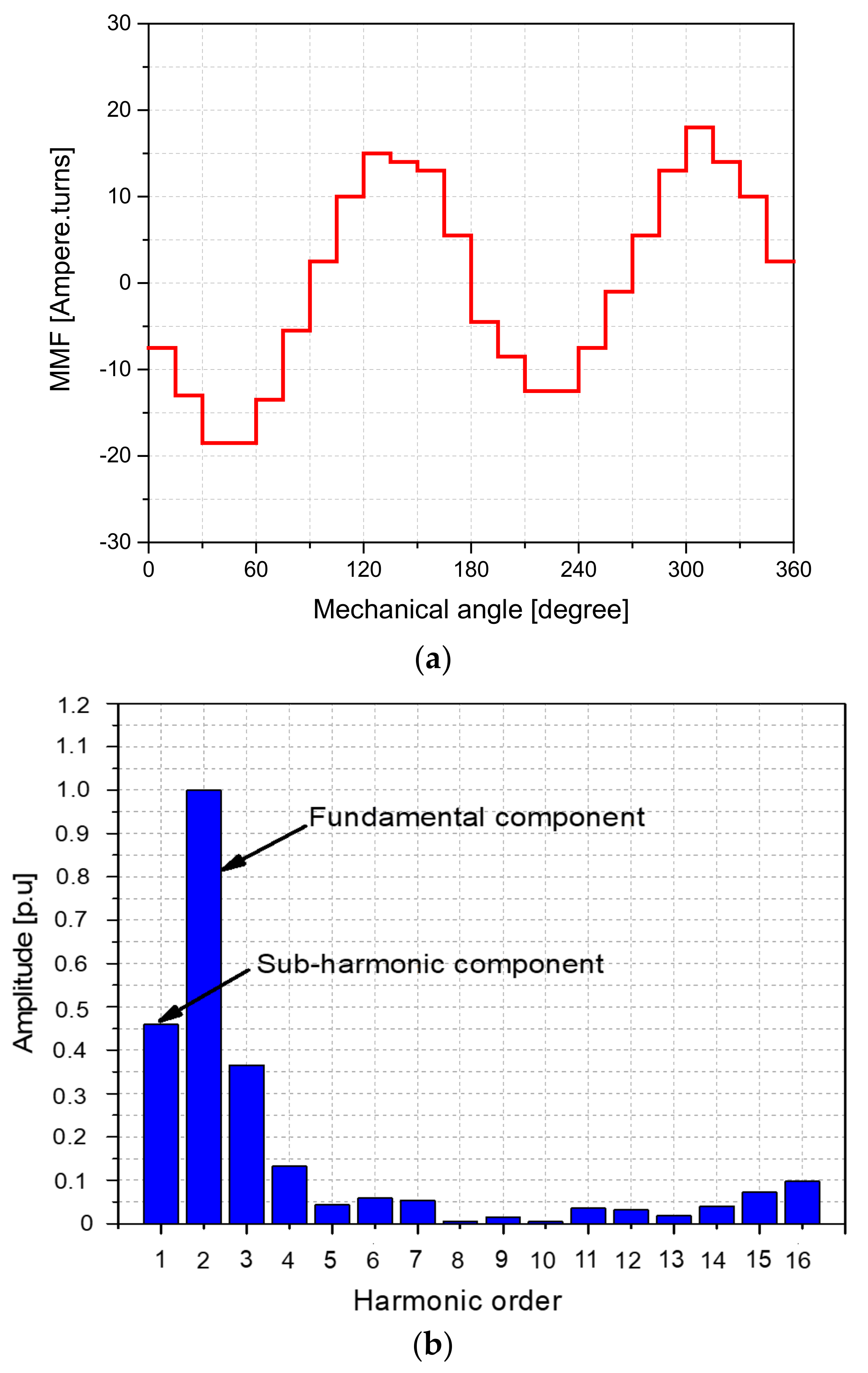
Iabc2 = 0.75 (p.u). This arrangement results in an MMF as presented in
Figure 7a. The FFT plot of this MMF as shown in
Figure 7b gives us the fundamental MMF component and the sub-harmonic MMF component of amplitude 0.46 (p.u). The amplitude of the sub-harmonic component of MMF for the proposed BL-WRSM topology is lower than the customary brushless topology. It is because that the customary BL-WRSM topology involves 12 full-filled slots for the injection of the low magnitude of current, whereas the proposed BL-WRSM topology requires 12 half-filled slots for the same purpose. The lower amplitude of the sub-harmonic, and the higher amplitude of the fundamental MMF components for the proposed BL-WRSM topology increases its output torque and efficiency.
The fundamental component of MMF generates the main field. On the other hand, the sub-harmonic MMF component induces the harmonic current in the harmonic winding. The induced harmonic current is rectified to energize the rotor field winding to attain brushless operation.
4. Electromagnetic Analysis
To validate the operation and investigate the performance of the customary and proposed BL-WRSM topologies based on sub-harmonic field-excitation technique, finite element analysis (FEA) is carried out using the JMAG-Designer version 19.1. A 4p24s machine is adopted from [
17] and is employed for this purpose whose parameters are listed in
Table 1. The FEA parameters of the employed machine are presented in
Table 2.
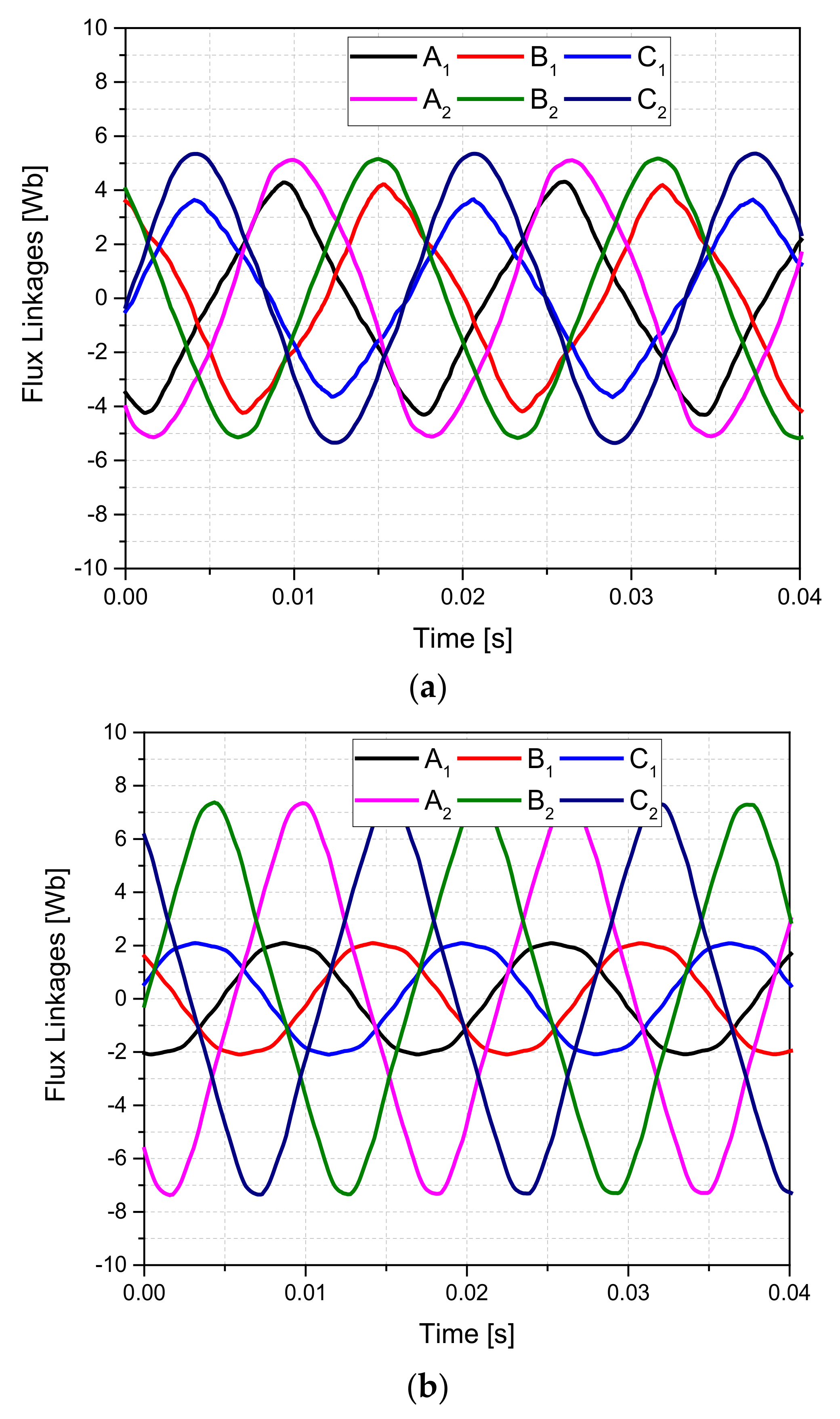
For the customary BL-WRSM topology, the first half of the armature winding is supplied with 5 A (peak) current through inverter-1, whereas the second half of the armature winding is delivered 3 A (peak) current using inverter-2. For the proposed BL-WRSM topology the magnitude of output currents for both inverters i.e., inverter-1 and 2 is kept the same as the customary BL-WRSM topology. The main armature winding current in the proposed BL-WRSM topology is supplied with 5 A (peak) and the additional armature winding is supplied with 3 A (peak). Both machines are operated at 1800 rpm and the simulations are carried out for 1 s. The flux linkages for
A1,
B1,
C1,
A2,
B2, and
C2 armature windings for the customary and proposed BL-WRSM topologies are shown in
Figure 8a,b.
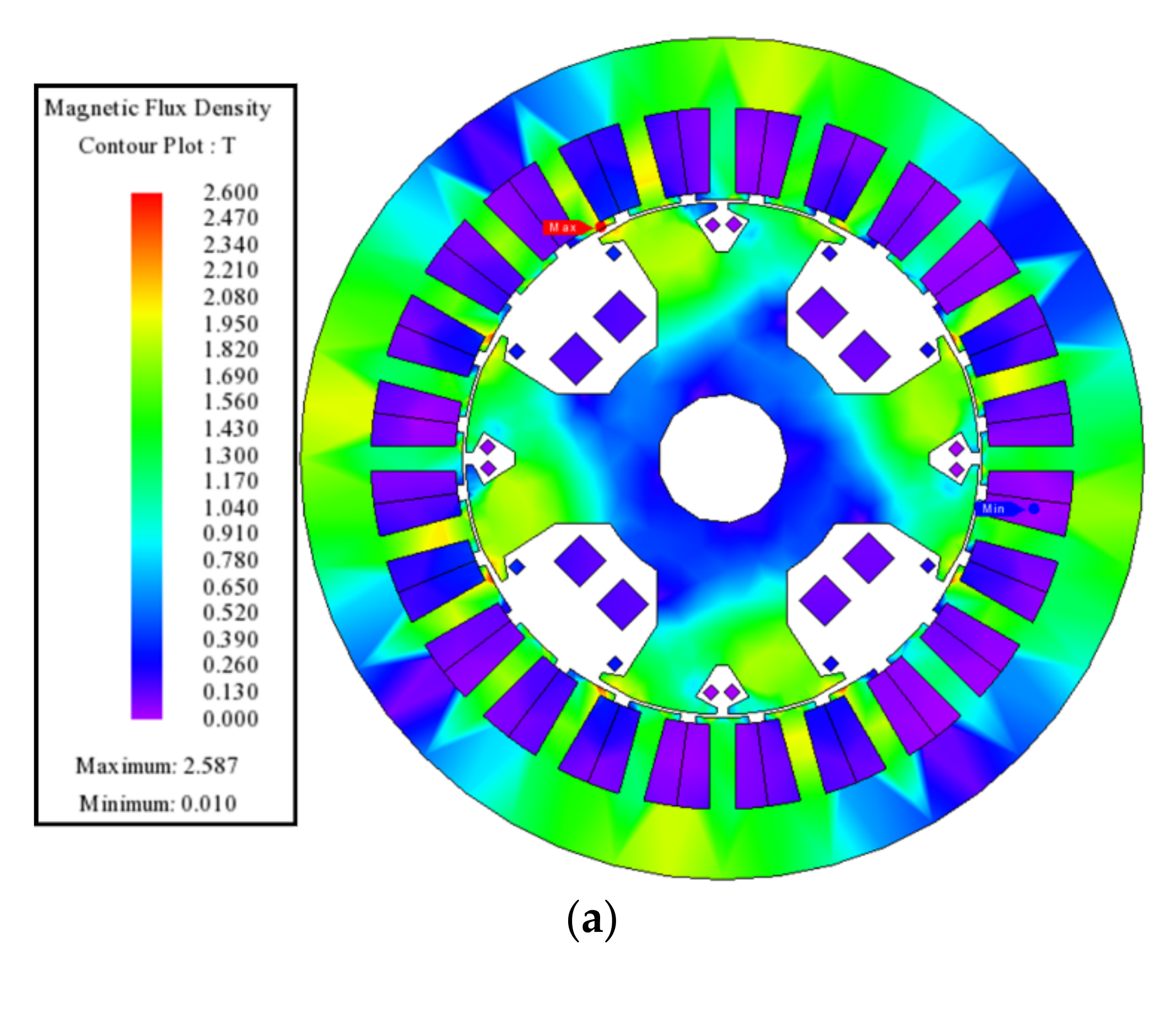
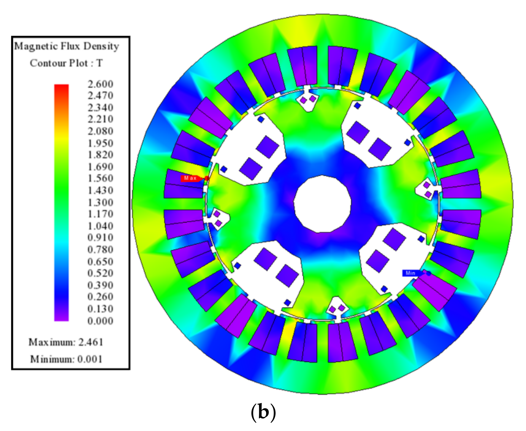
Figure 9a,b show the magnetic flux density distribution plots for the customary and proposed BL-WRSM topologies. These plots illustrate that the employed machine for the validation of the customary and proposed BL-WRSM topologies operates under the saturation levels of 2.5 T, and 2.4 T.
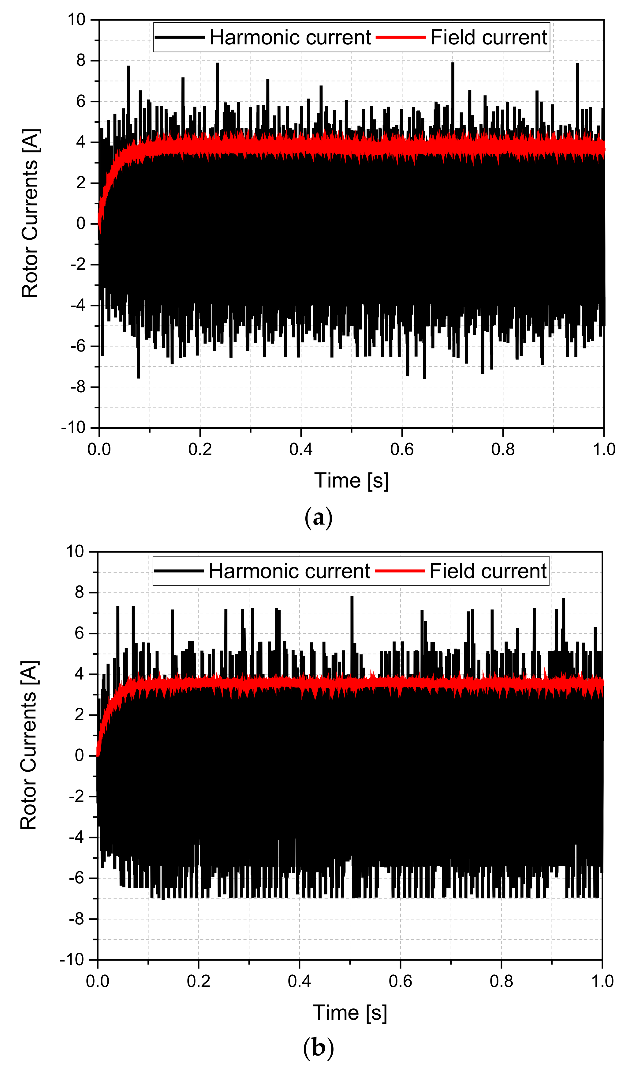
The net MMF of the employed machine using the customary and proposed BL-WRSM topologies consists of fundamental and sub-harmonic components. The fundamental component of the field is used to develop main stator field whereas the sub-harmonic component is employed to generate a harmonic current in the harmonic winding. The induced harmonic current is rectified to deliver DC to the rotor main field winding to develop the main rotor field. The induced harmonic and rectified field currents for the employed machine using customary and proposed BL-WRSM topologies are shown in
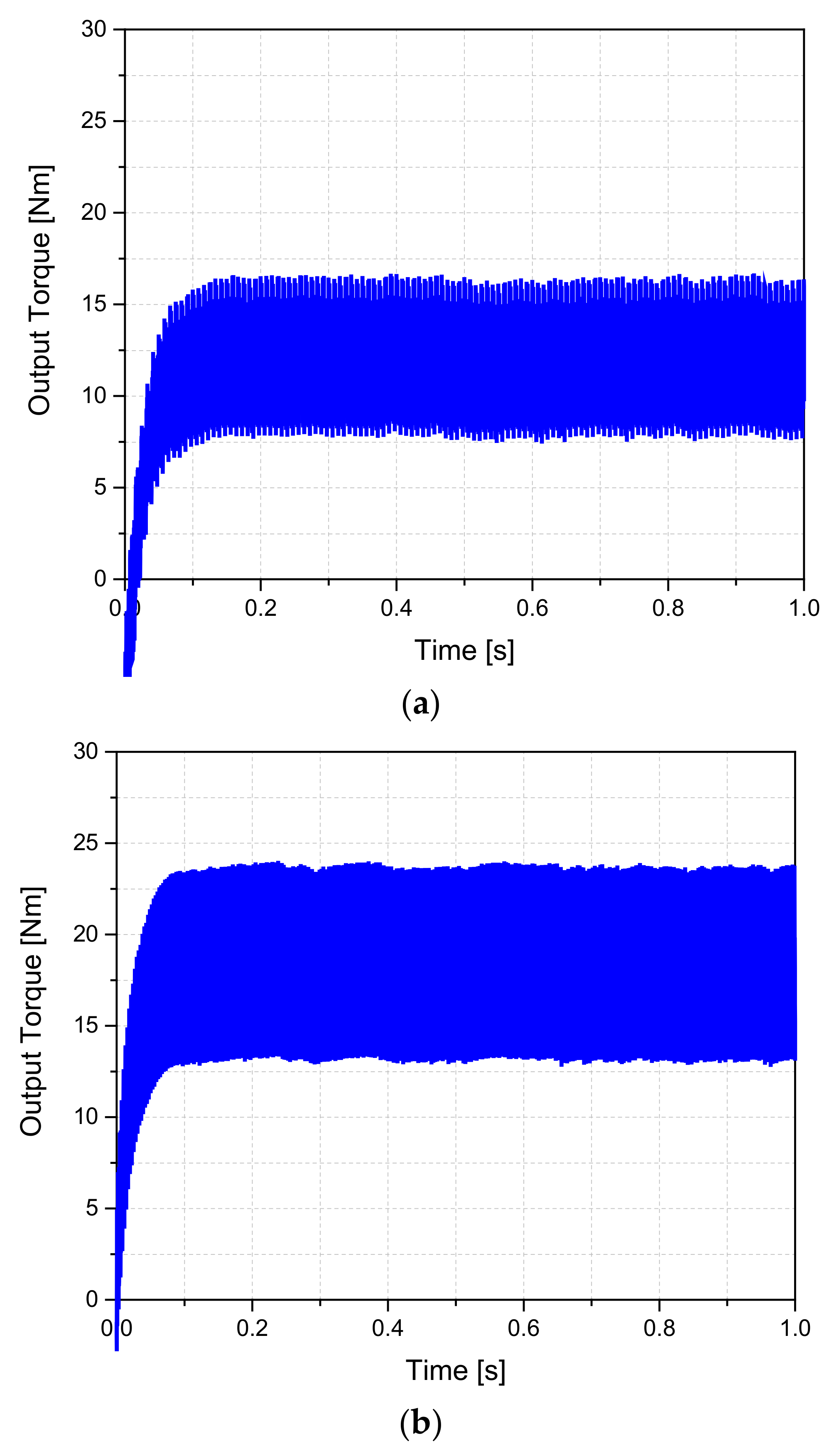
Figure 10a,b. These figures demonstrate that the average magnitude of the rectified field current in the case of the customary BL-WRSM topology is around 3.7 A; however, the magnitude of the same current for the proposed BL-WRSM topology is 3.5 A. This rectified current generates the main rotor field which when interacts with the main armature field generates torque. The magnitude of the average torque produced via the customary BL-WRSM topology is 11.8 Nm, whereas, for the proposed BL-WRSM topology based on sub-harmonic field excitation technique, the magnitude of the average output torque is around 17.8 Nm. The output torque of the customary and proposed WRSM topologies is shown in
Figure 11a,b. The torque ripple calculated for the customary and proposed BL-WRSM topologies is 75.9%, and 60.6%. To evaluate the efficiency of the customary and proposed BL-WRSM topologies, loss analysis is carried out in JMAG-Designer. From the analysis, we found that the stator and rotor iron and copper losses for the customary topology are 236.8 W and 50.8 W. However, for the proposed BL-WRSM topology these losses are calculated as 238.2 W, and 48.8 W. The total losses for the customary and proposed BL-WRSM topologies are calculated as 287.6 W and 287.1 W.
The efficiency of the customary topology is 88.6%, whereas for the proposed BL-WRSM topology, the efficiency is around 92.1%. From the results, it is evident that the proposed BL-WRSM topology based on the sub-harmonic field excitation technique generates 50.4% more torque than the customary BL-WRSM topology. On the other hand, the output torque ripple for the proposed topology is 15.3% lower than the customary BL-WRSM topology based on the sub-harmonic field excitation technique. Besides this, the efficiency of the proposed topology is 3.5% higher than the customary BL-WRSM topology. These results are also presented in
Table 3.
Unbalanced Radial Force
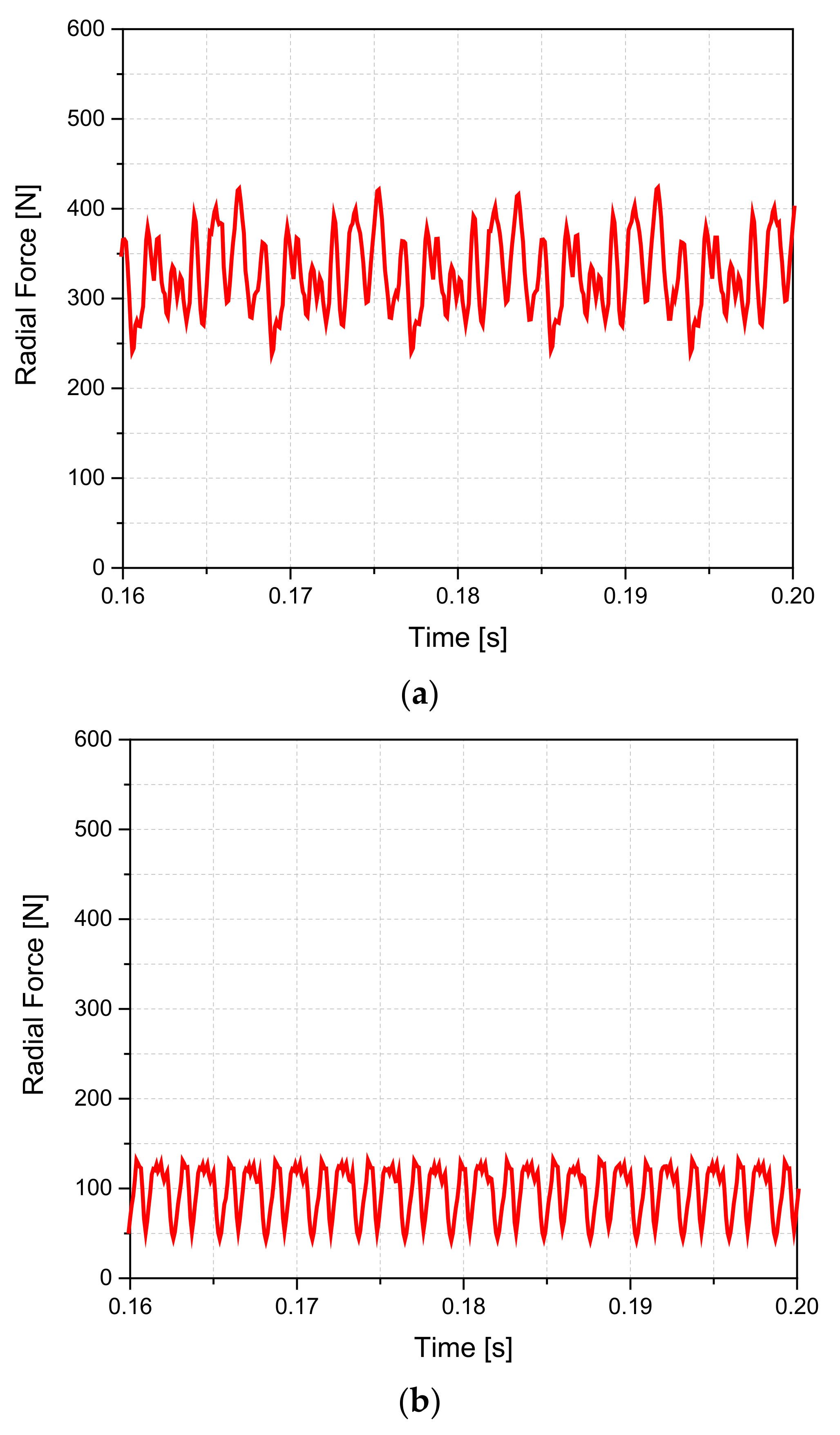
The customary and proposed BL-WRSM topologies work on the principle of the generation of sub-harmonics in airgap. These harmonics exert different magnitudes of forces on the different parts of the rotor. This results in an unbalanced radial force on the rotor. The high magnitude of unbalanced radial force has an adverse effect on the performance due to the generation of unequal stresses for the motor shaft and its bearings. In order to investigate the phenomenon of the generation of unbalanced radial forces for the employed machine using the customary and proposed BL-WRSM topologies based on sub-harmonic field excitation technique, FEA is carried out in JMAG-Designer. The net radial force plots for the employed machine using the customary and proposed BL-WRSM topologies are presented in
Figure 12a,b. It can be witnessed that the average value of the net radial force for the customary BL-WRSM topology is 329.2 N, whereas its magnitude is 97.6 N for the proposed topology. This shows that the magnitude of unbalanced radial force is decreased around 237% while adopting the proposed BL-WRSM topology as compared to the customary BL-WRSM topology.
5. Conclusions
A high-efficient BL-WRSM topology based on a sub-harmonic field-excitation technique was proposed in this paper. The proposed topology employed a 4-pole main armature and 2-pole additional armature windings; both were powered from two different inverters. The main armature winding was given a regular three-phase current, whereas the additional armature winding was delivered a lower magnitude of current to develop an MMF that contained fundamental and sub-harmonic MMF components. The fundamental component was utilized to create the main armature field; however, the sub-harmonic component was employed to generate a harmonic current in a harmonic winding, which was later rectified to deliver DC to the 4-pole rotor field winding to attain brushless operation.
A 4p24s machine was employed to investigate the performance of the customary and proposed BL-WRSM topologies. From the results, it is concluded that the proposed BL-WRSM topology generates 5.9 Nm more torque as compared to the customary BL-WRSM topology. Furthermore, the magnitude of the torque ripple for the proposed topology is 15.3% lower than the customary one. The efficiency of the proposed BL-WRSM topology is 5.3% higher than that of the customary topology. In addition, the average value of the net unbalanced radial forces is 231.6 N lower than the customary BL-WRSM topology based on the sub-harmonic field excitation technique.
From the results, it is concluded that the proposed BL-WRSM topology based on the sub-harmonic field-excitation technique performs better in terms of output torque, torque ripple, efficiency, and unbalanced radial forces as compared to the customary BL-WRSM topology.


