Abstract
This paper describes a study on the improvement of the dehydration performance of the conventional washing machine model. Recently, as interest in improving the dehydration performance of washing machines has increased, the need for a study on a high-speed electric motor has emerged. However, this conventional spoke-type PMSM has difficulty in speeding up due to the following problems. First, field weakening control is indispensable for high-speed operation of an electric motor. This control method is a big problem in causing torque drop and irreversible demagnetization of the motor. Moreover, the centrifugal force increases during high-speed operation, which adversely affects the stiffness of the motor. Therefore, in this paper, a new rotor shape of spoke-type PMSM was proposed to solve the above problem.
1. Introduction
1.1. Background of Study
As problems of depletion of petroleum resources and environmental pollution have emerged, interest in the development of high-performance electric motor technology is increasing. However, the rare earth used in the core parts of high-performance electric motors has large price fluctuations, and stable supply and demand are difficult because the reserves of resources are concentrated in several countries [1,2]. Therefore, pieces of research on motors that do not use rare earth have been actively conducted in recent years [3,4,5,6,7,8,9,10,11,12].
As a solution to the above problem, there is a plan to design a motor that does not use a permanent magnet. Typical such motors are switched reluctance motor (SRM) and synchronous reluctance motor (SynRM). SRM has a simple structure, low cost, and advantageous features for high-speed rotation, but has a low torque density compared to PM synchronous motors and has a problem in that vibration and noise are largely generated due to high torque reflow [3,4]. Likewise, SynRM also has a large torque ripple and has limitations in replacing rare earth permanent magnet motors due to its low torque density [5].
Another solution is to use Ferrite PM instead of a rare earth permanent magnet. Ferrite PM is in the spotlight as a substitute for rare earths because it is easier to supply and demand resources and is cheaper than rare earth permanent magnets [6,7]. However, since the residual flux density of ferrite magnets is significantly lower than that of rare earth permanent magnets, it is difficult to achieve the same performance as a motor using rare earth permanent magnets. For example, PM-assisted SynRM (PMASynRM), which combines SynRM with ferrite magnets, has lower performance compared to motors using rare earth permanent magnets [8,9].
Therefore, in general, ferrite PM is widely used in the spoke-type structure. Spoke-type PMSM is an electric motor that can concentrate flux by arranging permanent magnets facing each other in the radial direction. This structure creates a high airgap flux density because the fluxes from the two permanent magnets overlap each other and are directed to the airgap [10,11,12]. Therefore, ferrite PM, which is inexpensive, can perform similarly to a permanent magnet motor using rare earth.
Due to this performance of spoke-type PMSM, it was used only for hybrid motors for vehicles in the past, but it is recently being used for home appliances such as washing machines, dryers, and air conditioners. As mentioned above, although spoke-type PMSM has been applied in various ways to the home appliance field, its use is limited due to problems such as irreversible demagnetization and post-assembly magnetization of permanent magnets [13].
Recently, the need for high-speed operation of electric motors is increasing, but these conditions cannot be satisfied with conventional spoke-type PMSM. Therefore, in this paper, a study was conducted to improve the high-speed performance of the spoke-type PMSM and to improve the extant problems.
In general, in order to control a motor, it must be operated within a range that satisfies the voltage and current limits, so when the motor speed increases, field weakening control is performed. However, this causes irreversible demagnetization of the permanent magnet and lowers the torque density. In addition, the stiffness of the electric motor becomes weak due to the increase in centrifugal force during high-speed operation. Therefore, in order to increase the speed of the motor, the aforementioned problems must be solved. Therefore, in this paper, a study on the shape of a rotor capable of high speed was conducted to improve the dehydration performance of conventional spoke-type PMSM.
1.2. Operating Range of Cnventional Spoke-Type PMSM
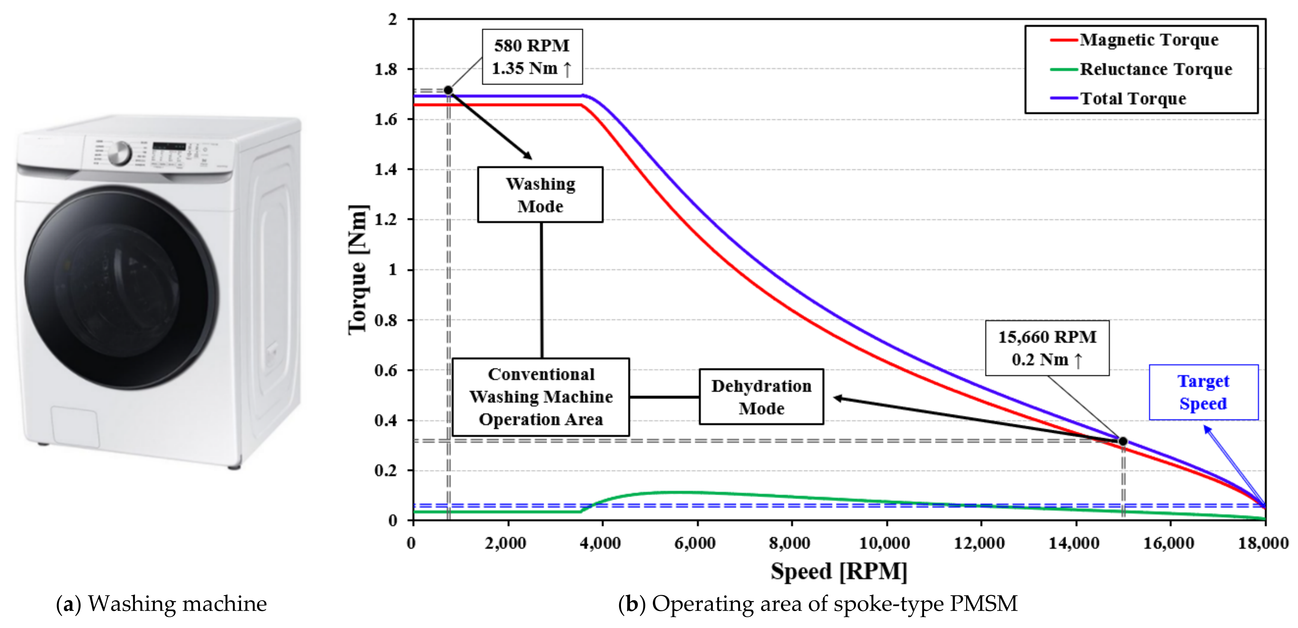
Figure 1a is the washing machine set as the target, and Figure 1b is the torque speed characteristic curve at the current limit of 2.3 Arms of the conventional spoke-type PMSM. The washing machine has two operating areas: washing mode and hydration mode. In the case of driving in the washing mode, since laundry and water are together, it moves at a low speed, but a high torque is required. On the other hand, in the hydration mode, water is removed, and a high torque is not required, but for quick dehydration, it must be operated at a high speed [14,15,16,17,18].
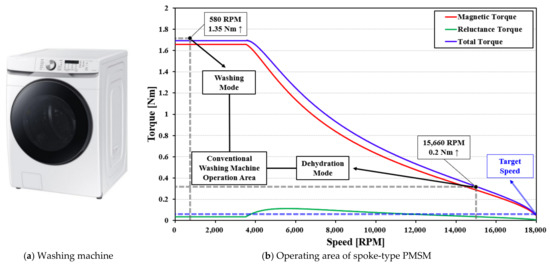
Figure 1.
Operation area of spoke type motor used in the conventional washing machine.
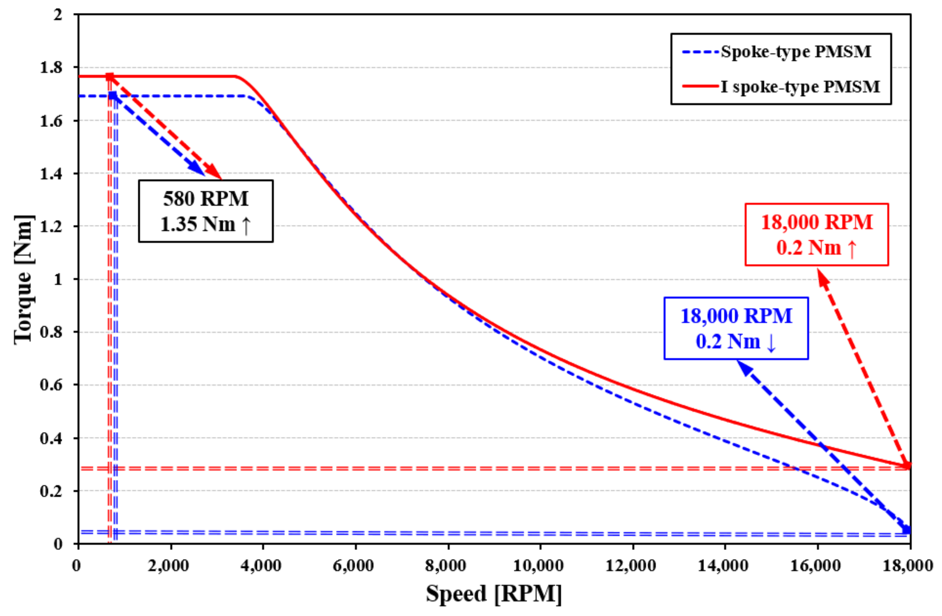
The target specification of the washing machine requires a torque of 1.35 Nm at low speed 580 RPM and 0.2 Nm at high speed 15,660 RPM. As can be seen from Figure 1b, the conventional spoke-type PMSM satisfies the operating range of the target specification.
However, as interest in improving dehydration performance has recently increased, the need for a high-speed electric motor is increasing. However, it indicates that the conventional spoke-type PMSM does not satisfy the target torque of 0.2 Nm when the speed increases above 16,000 RPM. Therefore, in this paper, a study was conducted on the shape of the rotor to improve the hydration performance, and the design was conducted to satisfy the target torque of 0.2 Nm at 18,000 RPM.
1.3. Features of the Proposed Model
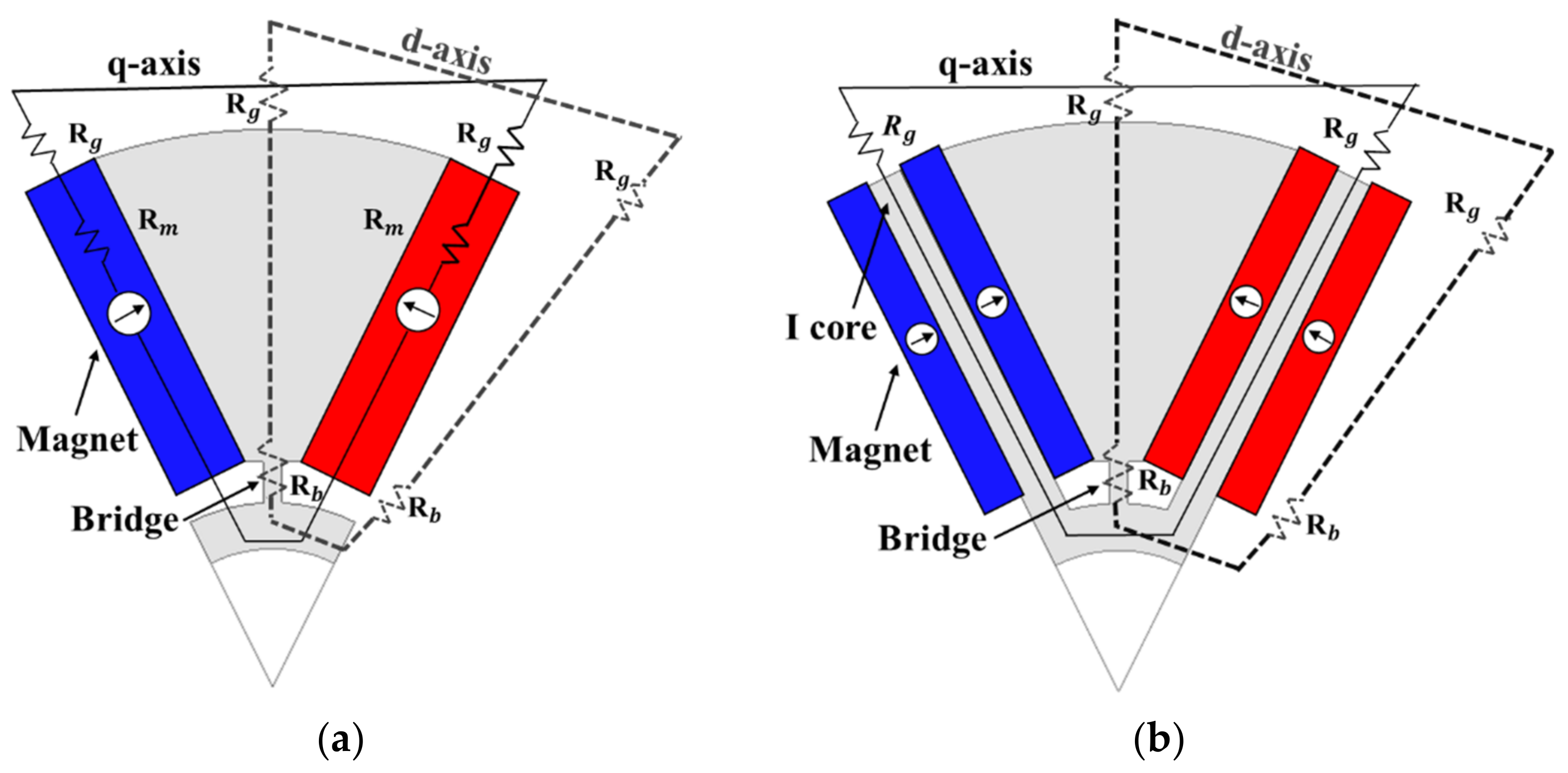
Figure 2a is the conventional spoke-type PMSM, and Figure 2b is the new rotor shape proposed in this paper for high-speed operation of motors. In Figure 2b, unlike the conventional spoke-type PMSM, the permanent magnet is divided in half, and an I-shaped iron core is inserted between the divided magnets. In this paper, for convenience, Figure 2b is named I spoke-type PMSM. Table 1 shows the properties of each material.

Figure 2.
(a) Conventional spoke-type PMSM; (b) proposed I spoke-type PMSM.

Table 1.
Properties of each material.
2. Study on the Shape of the Rotor to Satisfy High-Speed
2.1. IPMSM Torque Equation
Equation (1) shows the torque of IPMSM. Among the variables included in the equation, is magnetic torque, is reluctance torque, is pole pairs, is armature flux linkage by permanent magnet, is input current, β is current phase angle, is d-axis inductance, and is the q-axis inductance.
As can be seen from Equation (1), IPMSM can use reluctance torque as well as magnetic torque, and it indicates that the reluctance torque increases as the difference in d and q-axis inductance increases. Therefore, in this paper, a study was conducted on the shape of the rotor that can increase the reluctance torque to increase the speed of the motor.
2.2. Principle of Improving Reluctance Torque
Figure 3a is the conventional spoke-type PMSM, and Figure 3b is the magnetic equivalent circuit (MEC) of the I spoke-type PMSM proposed in this paper. Among the variables included in the above equations, , are d, q-axis inductance of spoke-type PMSM, and , are d, q-axis inductance of I spoke-type PMSM. Furthermore, , , are the resistance of air gap, bridge, and PM.
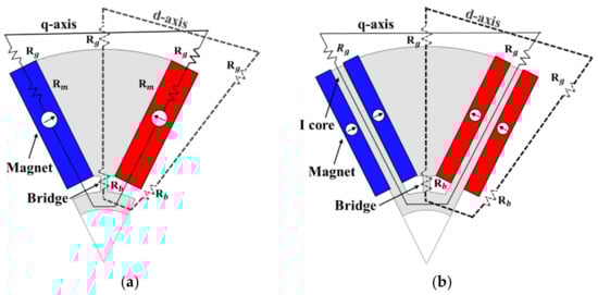
Figure 3.
MEC model, (a) spoke-type PMSM (b) I spoke-type PMSM.
Both motors have the same d-axis path, but there is difference in q-axis path. A permanent magnet is placed on the q-axis path of the conventional spoke-type PMSM, and the iron core is located in the case of the I spoke-type PMSM. Since the magnetic resistance of an iron core is significantly lower compared to that of a permanent magnet, I spoke-type PMSM has a higher q-axis inductance as expressed in Equation (7).
As a result, there is no difference in the d-axis inductance between the two models, but the q-axis inductance is higher in the proposed model, so the proposed model has a higher saliency ratio. It is expressed that the reluctance torque increases as the difference between the two inductances increases in Equation (3). Therefore, the I spoke-type PMSM has a higher reluctance torque than the conventional model.
2.3. Basic Model of I Spoke-Type PMSM
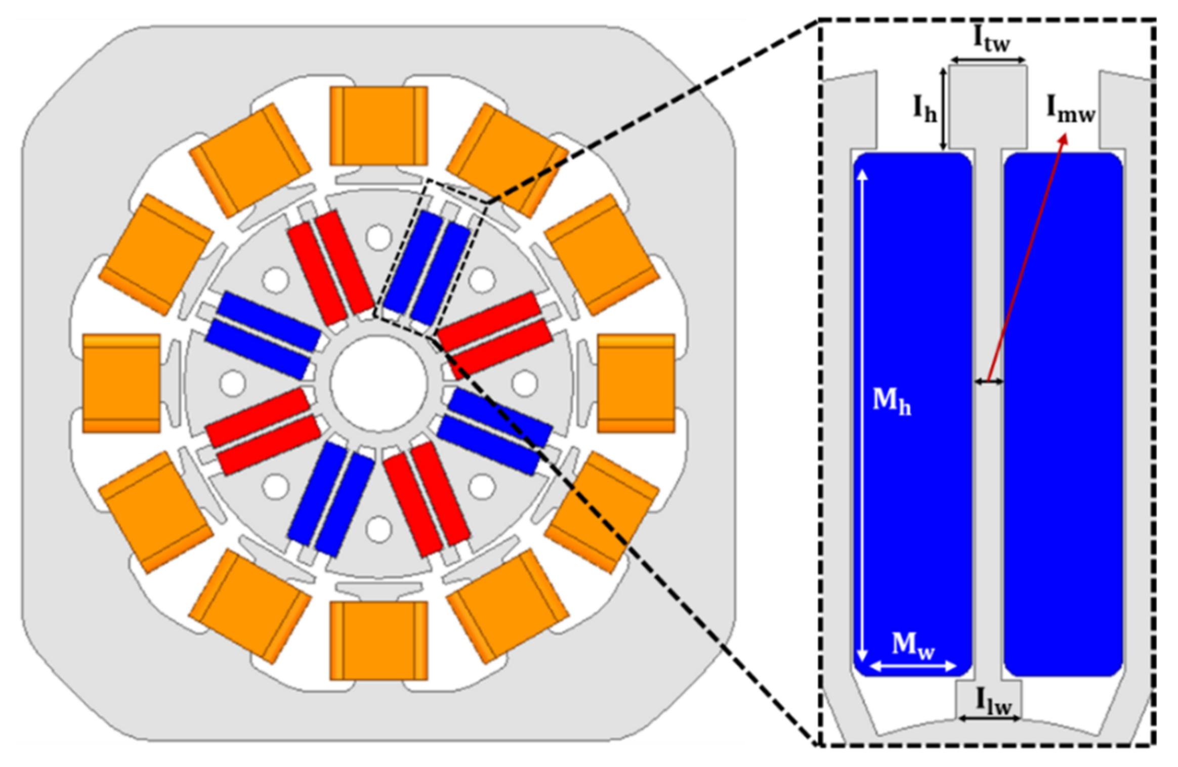
Figure 4 is the basic design model of I spoke-type PMSM. Among the variables included in the above equations, , , and are the widths of the top, middle, and bottom of the I-core, and is the height of the top of the I-core. In addition, and represent the height and width of one permanent magnet.

Figure 4.
Basic design of I spoke-type PMSM.
Increasing the length of and supports the permanent magnet stably. However, this simultaneously acts as a leakage path of the flux and lowers the power density of the motor. Therefore, in this paper, the lengths of and are selected as 2.2 mm, which is the minimum length that can support the permanent magnet while minimizing the leakage path.
and are key factors in increasing q-axis inductance. Therefore, was selected as 2.5 mm and as 0.7 mm to ensure sufficient reluctance torque within the range not exceeding the rotor diameter. For the same magnet usage as the conventional spoke-type PMSM, was selected as 16.05 mm and was selected as 3.6 mm.
2.4. FEA Analysis
Figure 5 shows the d and q-axis inductance of two motors according to the current phase angle change. In the case of the I spoke-type PMSM, it indicates that the q-axis inductance is greatly increased. This is because the iron core with low magnetic resistance is located in the q-axis path as shown in the MEC in Figure 3.
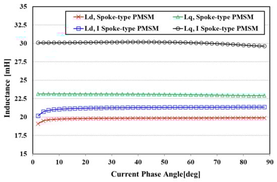
Figure 5.
Comparison of d, q-axis inductance.
In the case of d-axis inductance, there is a slight difference between the actual analysis result and the MEC result. This is because a certain amount of flux flows through the iron core between the permanent magnets, so the I spoke-type PMSM has slightly higher d-axis inductance. However, since the increase in q-axis inductance compared to the increase in d-axis inductance is large, the I spoke-type PMSM has a higher saliency ratio and a higher reluctance torque.
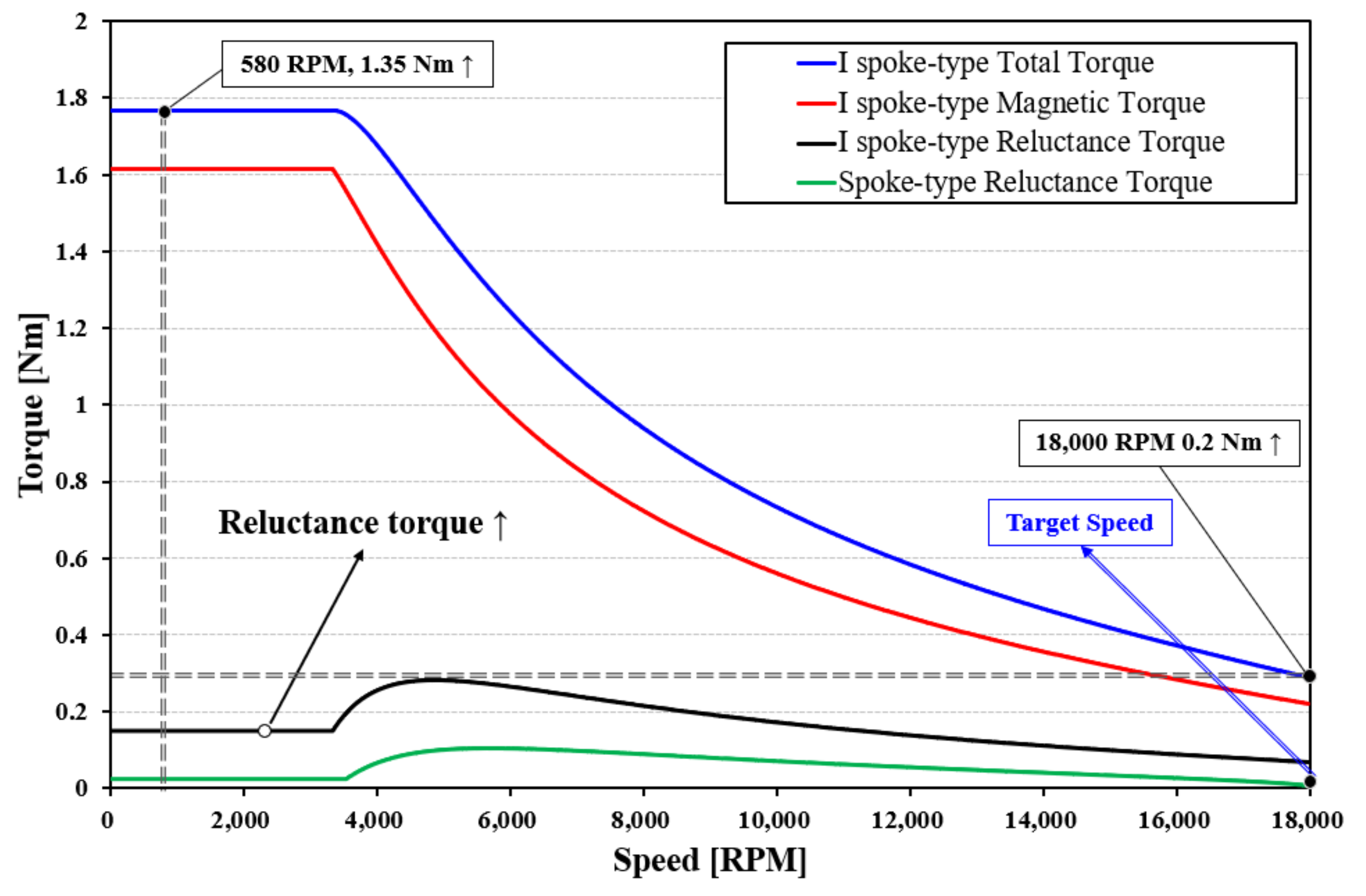
Figure 6 is the torque-speed characteristic curve of I spoke-type PMSM, and Figure 7 is the result of comparing the torque-speed characteristics of both models. In summary, the I spoke-type PMSM has a higher saliency ratio than the conventional spoke-type PMSM. As a result, Figure 6 shows that the reluctance torque of the I spoke-type PMSM increased significantly. Therefore, Figure 7 shows that the conventional model did not satisfy the target torque of 0.2 Nm at 18,000 RPM, but the proposed model has a torque of 0.2 Nm or more.

Figure 6.
T-N curve of I spoke-type PMSM.
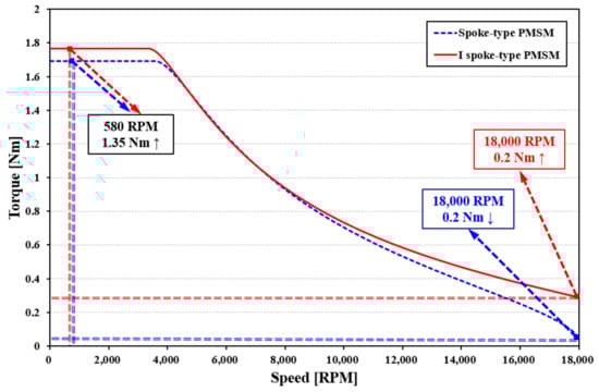
Figure 7.
Comparison of T-N curve.
Figure 8 shows the current limit circle of the two models and the voltage limit ellipse at 18,000 RPM. The midpoints of each voltage limit ellipses are marked by and , the blue line represents the voltage limit ellipse of the conventional spoke-type PMSM, the red line represents the voltage limit ellipse of the I spoke-type PMSM, and the green line represents the current limit circle.
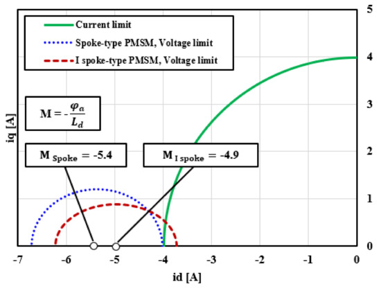
Figure 8.
Comparison of operating range at 18,000 RPM.
Figure 8 shows that there is a difference between the voltage limit ellipse weight of the conventional spoke-type PMSM and the I spoke-type PMSM. Equation (8) supports the results of Figure 8 by showing that the midpoint position of the voltage limit ellipse is inversely proportional to the d-axis inductance and proportional to the flux linkage. When comparing the d-axis inductance shown in Figure 5, it indicates that the I spoke-type PMSM has higher inductance than the conventional spoke-type PMSM. Therefore, the midpoint of the voltage limit ellipse of the I spoke-type PMSM is located closer to the origin than the conventional spoke-type PMSM.
The area where the motor can be operated can only be indicated at the intersection of the voltage limit ellipse and the current limit circle. With the movement of point M, the voltage limit ellipse of the I spoke-type PMSM has an intersection with the current limit circle, but the conventional spoke-type PMSM does not have an intersection. Therefore, as shown in Figure 8, the conventional spoke-type PMSM at 18,000 RPM cannot be operated because the intersection of voltage limit ellipse and current limit circle does not exist. On the other hand, the I spoke-type PMSM can operate a motor because the intersection of the ellipse and the circle exists.
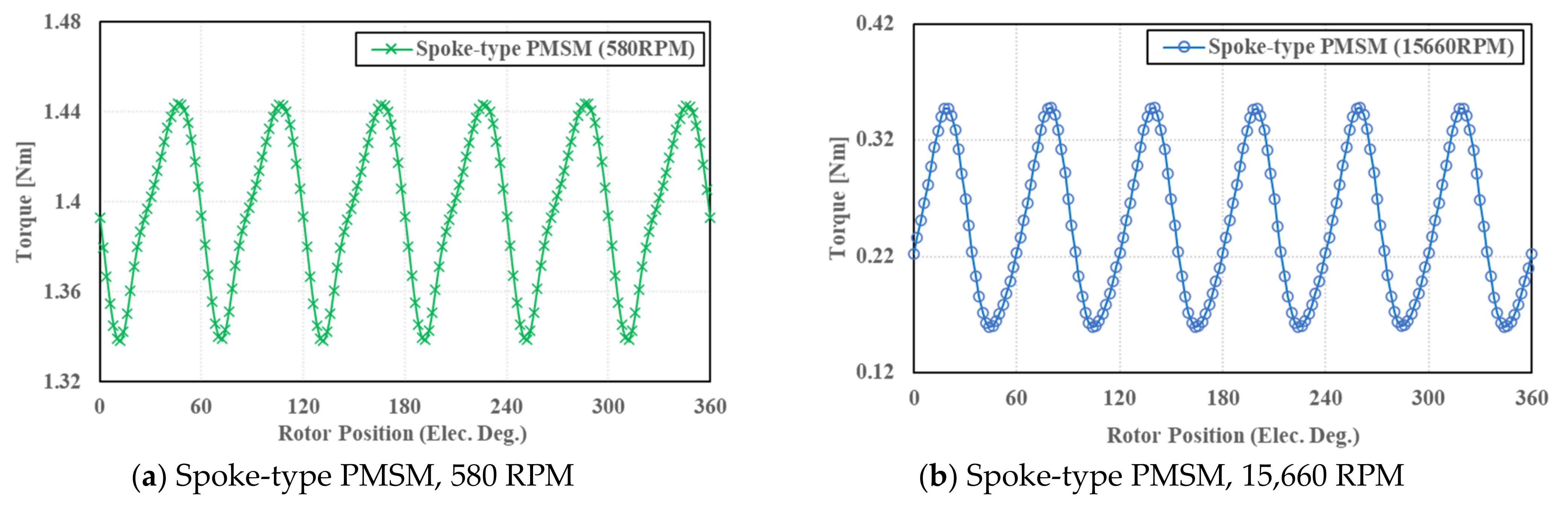
Table 2 shows the motor specifications used in FEA, and Table 3 shows the torque ripple ratio of each of the two motors. Table 3 provides information that the spoke-type PMSM generates 7.6% torque ripple at 580 RPM and 76.4% at 15,660 RPM. Moreover, the I spoke-type PMSM has 5.6% torque ripple at 580 RPM and 105.8% torque ripple at 18,000 RPM. The torque ripple ratio of the I spoke-type PMSM is higher than that of the spoke-type PMSM in the high-speed operation area because of the high amount of reluctance torque used.
Table 2.
Motor parameters of spoke-type and I spoke-type PMSM.
Table 3.
Torque ripple comparison of two motors.
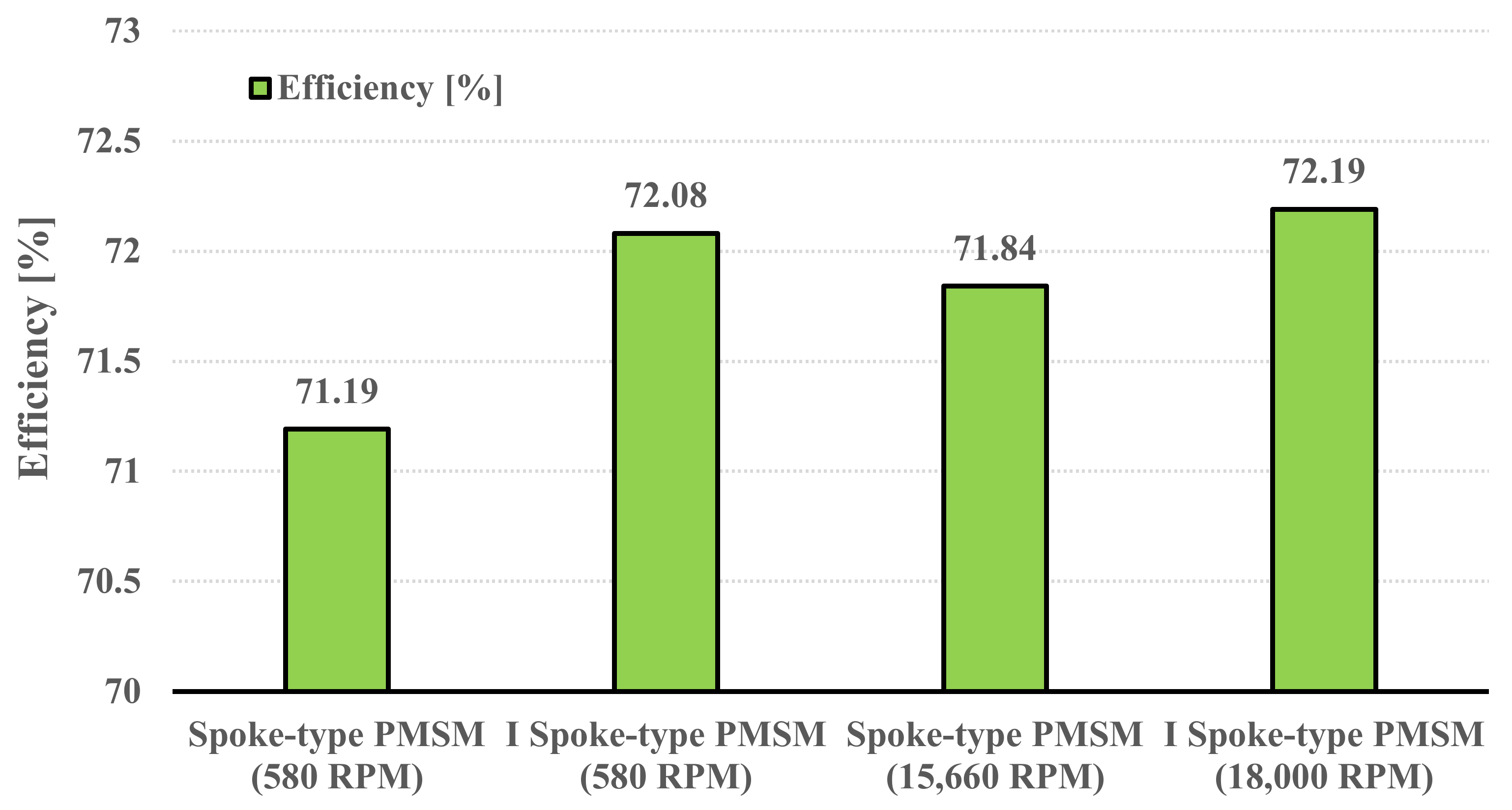
Figure 9, Figure 10 and Figure 11 are FEA results for torque ripple, loss, and efficiency at each operating point. The T-N curve shows the information that the spoke-type PMSM has a maximum operable speed of 15,660 RPM. On the other hand, the I spoke-type PMSM can use reluctance torque and can be operated at 18,000 RPM or higher. Therefore, Table 3 provides torque ripple, loss, and efficiency results of 580 RPM and 15,660 RPM for spoke-type PMSM and torque ripple, loss, and efficiency at 580 RPM and 18,000 RPM for I spoke-type PMSM.
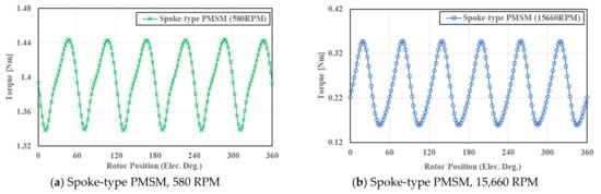
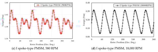
Figure 9.
Torque ripple according to each operation of the two motors.
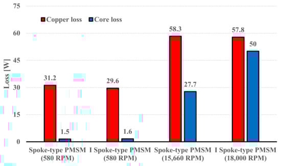
Figure 10.
Loss at each operating point of both motors.
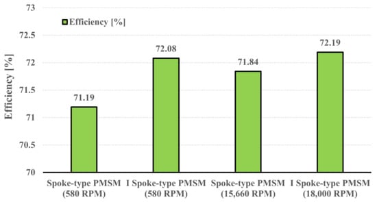
Figure 11.
Efficiency at each operating point of both motors.
Figure 10 and Figure 11 show the loss and efficiency of the two motors due to the change in the operating area. These results indicate the loss and efficiency at the above two points because the target operating speed must satisfy 1.35 Nm at 580 RPM and 0.2 Nm at 18,000 RPM. Compared with these results, the spoke-type PMSM was compared with loss and efficiency at 15,660 RPM because the maximum operable speed is 15,660 RPM.
Figure 10 shows that the I spoke-type PMSM has lower copper losses than the spoke-type PMSM because it uses additional reluctance torque. In the case of iron loss, since it is proportional to the speed, the iron loss appears low in the low-speed operation range of 580 RPM.
On the other hand, iron loss increases in the high-speed operation area. Since the I spoke-type PMSM operates at 18,000 RPM, the iron loss is higher than the spoke-type PMSM measured at 15,660 RPM.
Figure 11 shows the efficiency of both motors. For high efficiency, either loss is reduced or output is increased. At 580 RPM, the I spoke-type PMSM has lower copper losses than the spoke-type PMSM. Therefore, the I spoke-type PMSM showed higher efficiency. In the case of high-speed operation, the I spoke-type PMSM has a large loss due to high iron loss, but the I spoke-type has higher output due to the increased driving speed.
Therefore, the efficiency of the I spoke-type PMSM is higher than that of the spoke-type PMSM. Finally, the I spoke-type PMSM can operate at higher speeds and has higher efficiency compared to the spoke-type PMSM.
3. Irreversible Demagnetization
3.1. Irreversible Demagnetizaiton Specification
As shown in Figure 1, the motor used in the washing machine must satisfy both the low and high-speed operating ranges. As the motor speed increases, the voltage rises together, but for motor control, it must be operated within the specified voltage limit.
Therefore, the permanent magnet motor performs field-weakening control as the speed increases in order not to exceed the voltage limit.
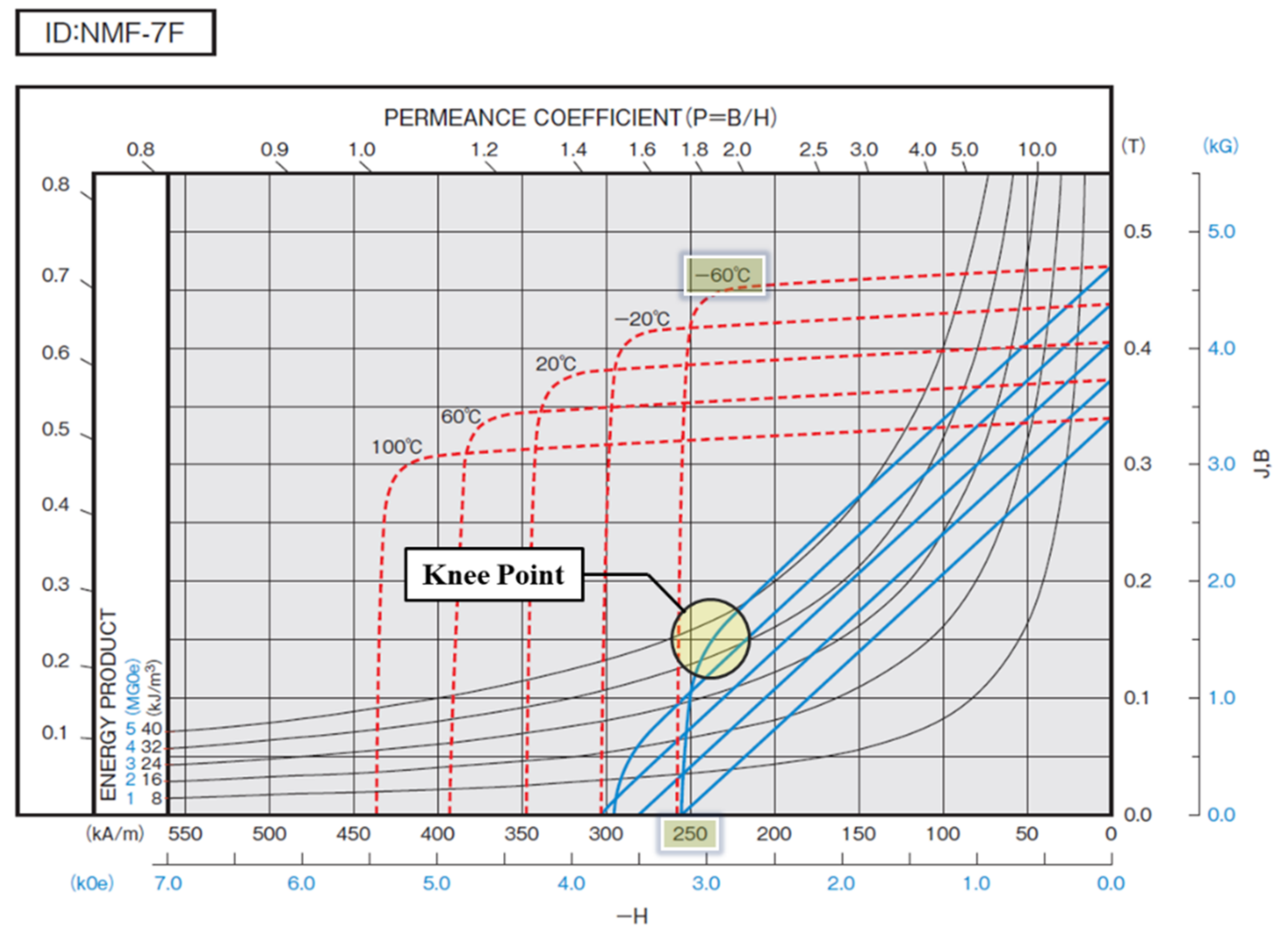
The field-weakening control is a method of lowering the voltage by applying an inverse magnetic field to a permanent magnet. However, if this inverse magnetic field acts excessively and the operating point is formed below the knee point, irreversible demagnetization of the permanent magnet occurs [19].
Irreversible demagnetization is related to the performance degradation of permanent magnets, so all permanent magnet motors must be designed in consideration of this. The specifications used in the actual irreversible demagnetization analysis are shown Table 4.
Table 4.
Specification for irreversible demagnetization analysis.
Figure 12 shows the permanent magnet data used in the irreversible demagnetization analysis [20]. Ferrite PM has a low-temperature demagnetization characteristic because the coercive force decreases as the temperature decreases.
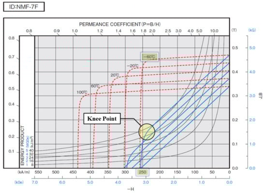
Figure 12.
B-H curve according to the temperature of ferrite permanent magnet (NMF-7) [20].
Therefore, the simulation was conducted based on the B-H curve data of −60 °C which is the extreme condition, and the demagnetization current was analyzed by applying 10.6 Arms, the maximum allowable current of the inverter.
3.2. Irreversible Demagnetization Analysis
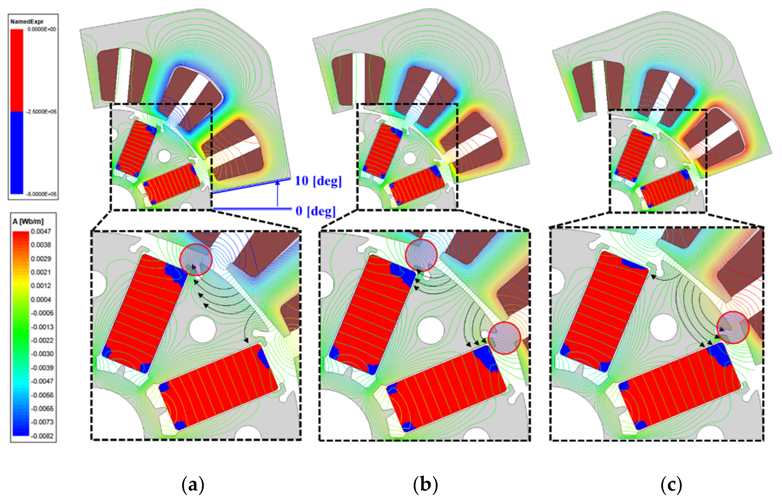
Figure 13 and Figure 14 show the irreversible demagnetization area according to the shape of the rotor. As the rotor rotates, the distribution of the inverse magnetic field affecting the permanent magnet changes. In consideration of this, the irreversible demagnetization phenomenon was analyzed by changing the position of the stator after fixing the rotor.
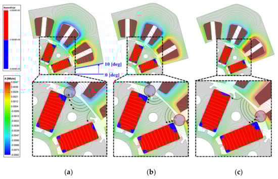
Figure 13.
Irreversible demagnetization area of spoke-type PMSM. (a) 10 deg; (b) 15 deg; (c) 20 deg.
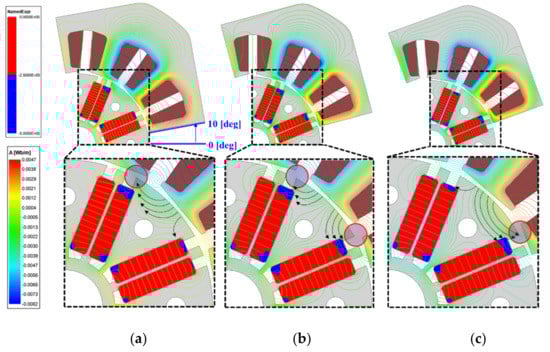
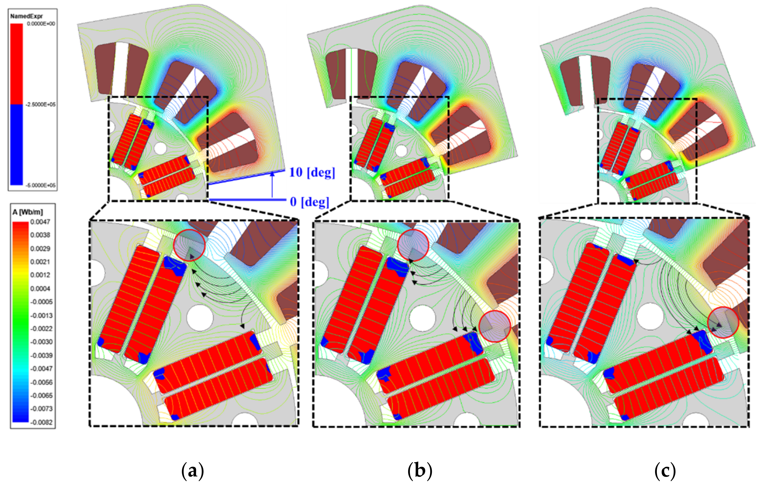
Figure 14.
Irreversible demagnetization area of I spoke-type PMSM. (a) 10 deg; (b) 15 deg; (c) 20 deg.
As a result of the analysis, it is shown in Figure 13 and Figure 14 that irreversible demagnetization occurs significantly when the stator positions are 10, 15, and 20 deg.
In the above figure, the magnetic flux distribution diagram was expressed using red circles and arrows to analyze the cause of irreversible demagnetization. The red circle is the area where the flux is concentrated, the direction of the black arrow is the direction of the flux, and the number of arrows is the approximate size of the flux. The blue part of the permanent magnet is the irreversible demagnetization area.
As can be seen from Figure 13 and Figure 14, as the stator rotates, the flux path flowing through the pole piece changes. It indicates that the flux is concentrated on the left side of the rotor at 10 deg, both sides at 15 deg, and on the right at 20 deg. It indicates that the irreversible demagnetization generation region and the flux concentration region coincide with each other at each angle.
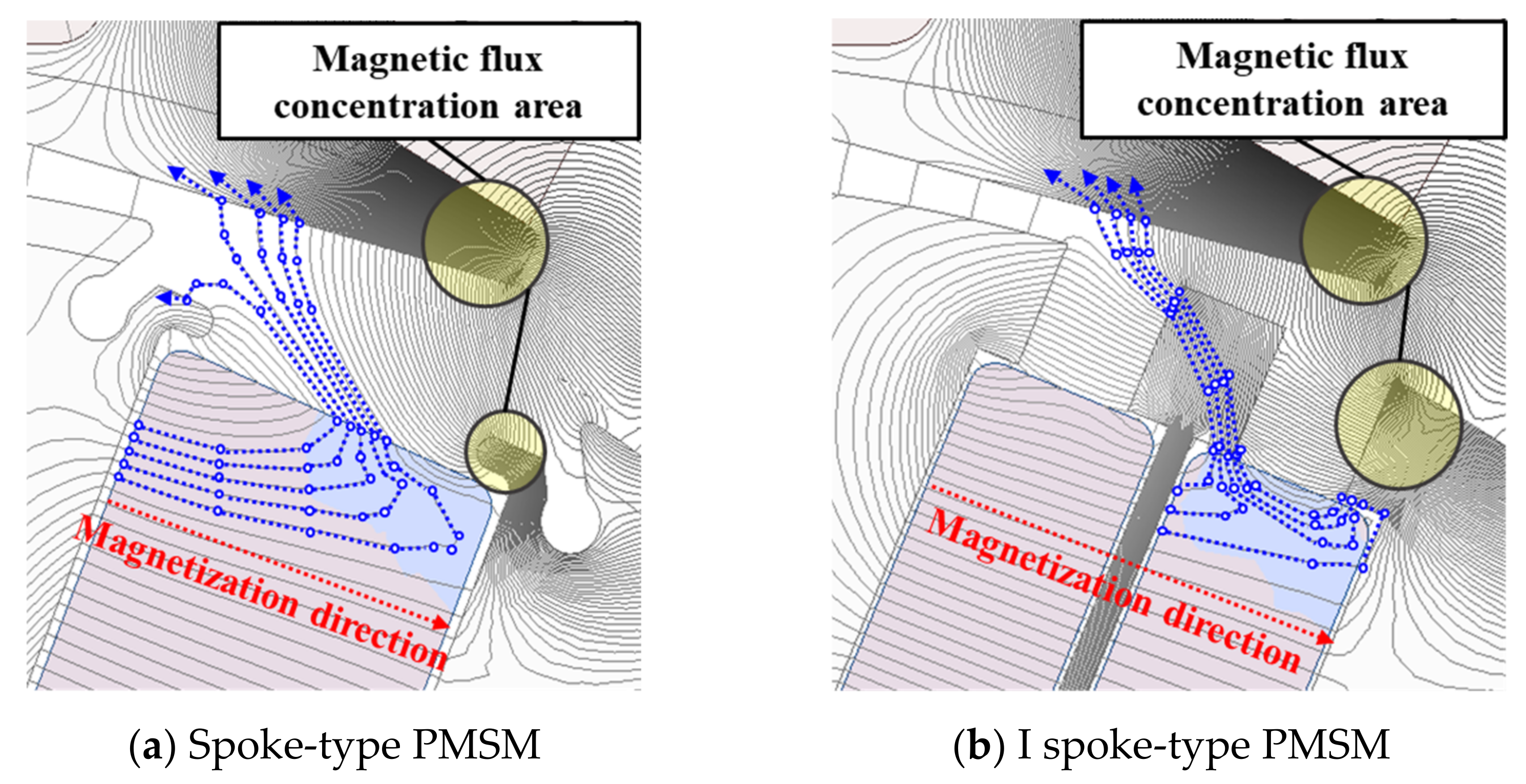
In other words, irreversible demagnetization is correlated with the concentration of the inverse magnetic flux generated in the stator. Therefore, the largest irreversible demagnetization occurred at 15 deg in both models. However, in the I spoke-type PMSM, irreversible demagnetization occurred in the inner permanent magnet based on the I-core, but irreversible demagnetization did not occur in the outer permanent magnet. The cause of the above phenomenon is related to the magnetic flux path, and it can be explained by showing the magnetic flux path according to the shape of the rotor in Figure 15.
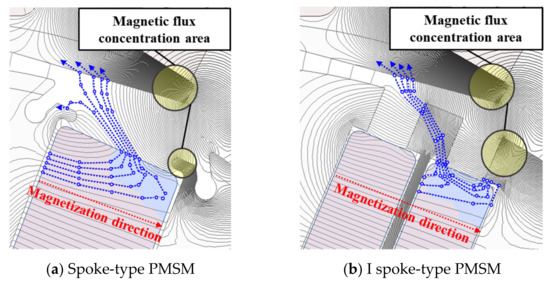
Figure 15.
Comparison of flux-line according to the rotor shape.
Figure 15 shows the flux-line of the two models when the stator is positioned at 15 deg. The red dotted arrow is the magnetization direction of the permanent magnet, and the blue line is the path of the flux passing through the region where irreversible demagnetization has occurred.
When comparing the characteristics of the region where irreversible demagnetization occurs in the permanent magnet in Figure 15, it indicates that it occurs when the flux line passing through the permanent magnet and the magnetization direction of the permanent magnet are inconsistent.
This inconsistency phenomenon occurs because the flux is concentrated at the ends of the ribs and shoes indicated by the yellow circles in Figure 15. Flux is directed to a place with low magnetic resistance, so a magnetic flux path is formed with a stator rather than a pole piece. As a result, there is a discrepancy between the flux traveling direction and the magnetization direction of the permanent magnet, and irreversible demagnetization occurs.
In Figure 15b, the I spoke-type PMSM is also bypassed by the flux-line to the stator as in Figure 15a. However, irreversible demagnetization occurred in the inner permanent magnet based on the I-core in a similar form to the previous one, but irreversible demagnetization did not occur in the outer permanent magnet. In the case of the permanent magnet located outside, since the flux can easily pass through the I-core, irreversible demagnetization does not occur.
3.3. EMF and Demagnetization Comparison before and after Irreversible Demagnetization
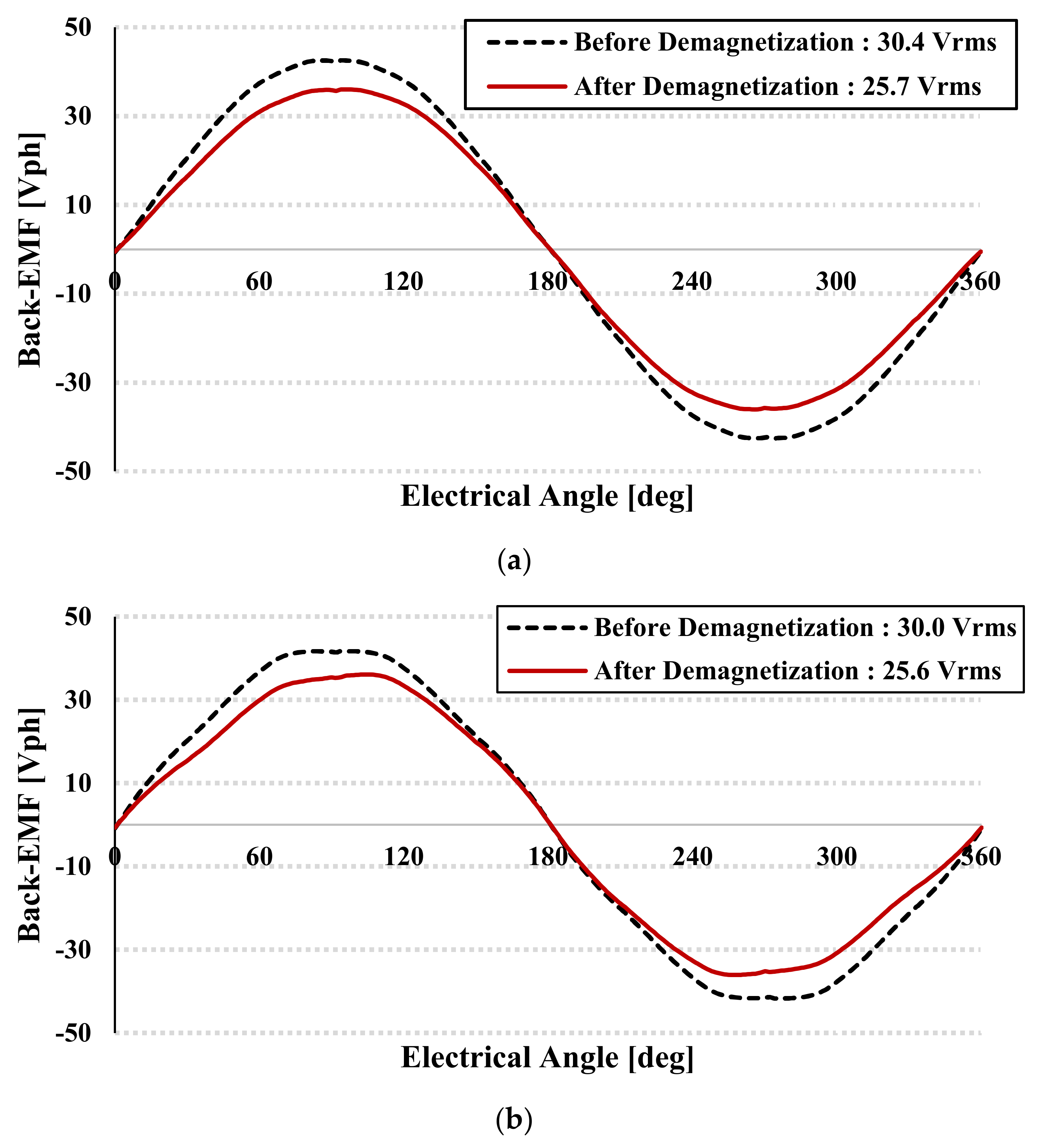
Figure 16 and Table 5 are the analysis results of back EMF and irreversible demagnetization ratio before and after demagnetization. Comparing the irreversible demagnetization of the two models, the conventional spoke-type PMSM is 15.5% and the I spoke-type PMSM is 14.7%. In other words, it indicates that the I spoke-type PMSM has a lower irreversible demagnetization rate.

Figure 16.
Comparison of Back-EMF before and after irreversible demagnetization. (a) Spoke-type PMSM No-load Back-electromotive force, 1000 [RPM]; (b) I spoke-type PMSM No-load Back-electromotive force, 1000 [RPM].
Table 5.
Comparison of irreversible demagnetization.
4. Magnetization Analysis
4.1. General Magnetization Methods of PMSM
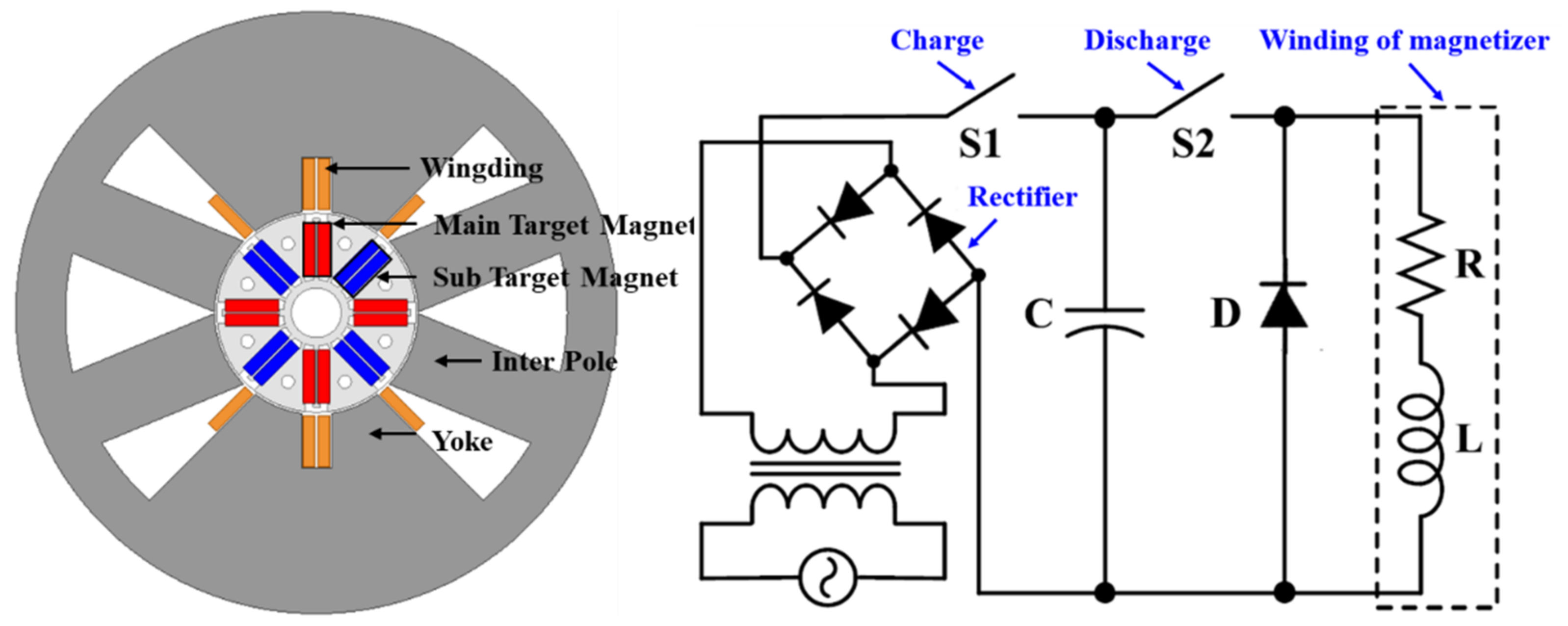
In general, permanent magnet motors mainly use a post assembly magnetization method to improve productivity when magnetization is performed [21,22,23,24]. However, unlike the surface permanent magnet synchronous motor (SPMSM) shown in Figure 17, when post assembly magnetization is performed in the spoke-type PMSM, the magnetic field is divided in half at the pole-piece and flows into the permanent magnet.
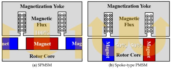
Figure 17.
Path of the magnetization flux in PMSM.
Therefore, in order to achieve the same magnetization performance as SPMSM, it is necessary to make more magneto-motive force from the magnetization than SPMSM. In addition, since the spoke-type PMSM has a narrow bottom part of the rotor, the magnetic field cannot fully reach the permanent magnet located close to the shaft.
Furthermore, since the post assembly magnetization method has to be repeated several times for perfect magnetization, productivity is lowered compared to the conventional magnetization method.
Finally, as a method to solve this problem, the spoke-type PMSM uses a split magnetization method. The split magnetization is a magnetization technique capable of improving the magnetization rate of a permanent magnet by concentrating a magnetized magnetic field on a specific permanent magnet.
Figure 17 shows the split magnetization yoke and the split magnetization principle. In this paper, we proposed an I spoke-type PMSM that can reduce the number of magnetizations while taking advantage of the increase in magneto-motive force from the magnetization, which is an advantage of the split magnetization method [25].
4.2. Principle of Split Magnetization—MEC (Magnetic Equivalent Circuit)
In the figure above, are the resistances of yoke, air, teeth, magnet, and inter pole. are the magnetic fluxes directed to the left and right, is the magnetic flux generated by the teeth, and F is the magnetomotive force. and calculated based on the above MEC are as follows.
Analyzing the MEC in Figure 18, created by the magnetomagnetic force F flows dividedly to the left and right based on the n point. It indicates that the magnetic resistances located in the direction of the red and green arrows shown in the figure are different.
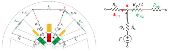
Figure 18.
(a) MEC model of magnetization, (b) Simplified MEC model.
Therefore, flows by dividing according to the ratio of magnetic resistance shown in Equations (9) and (10), and like Equation (11), the magnetic flux of directed to the left based on point n has a higher value. As a result, the permanent magnet located in the red area receives the highest magnetic field, and the permanent magnet located in the green area receives a smaller magnetic field.
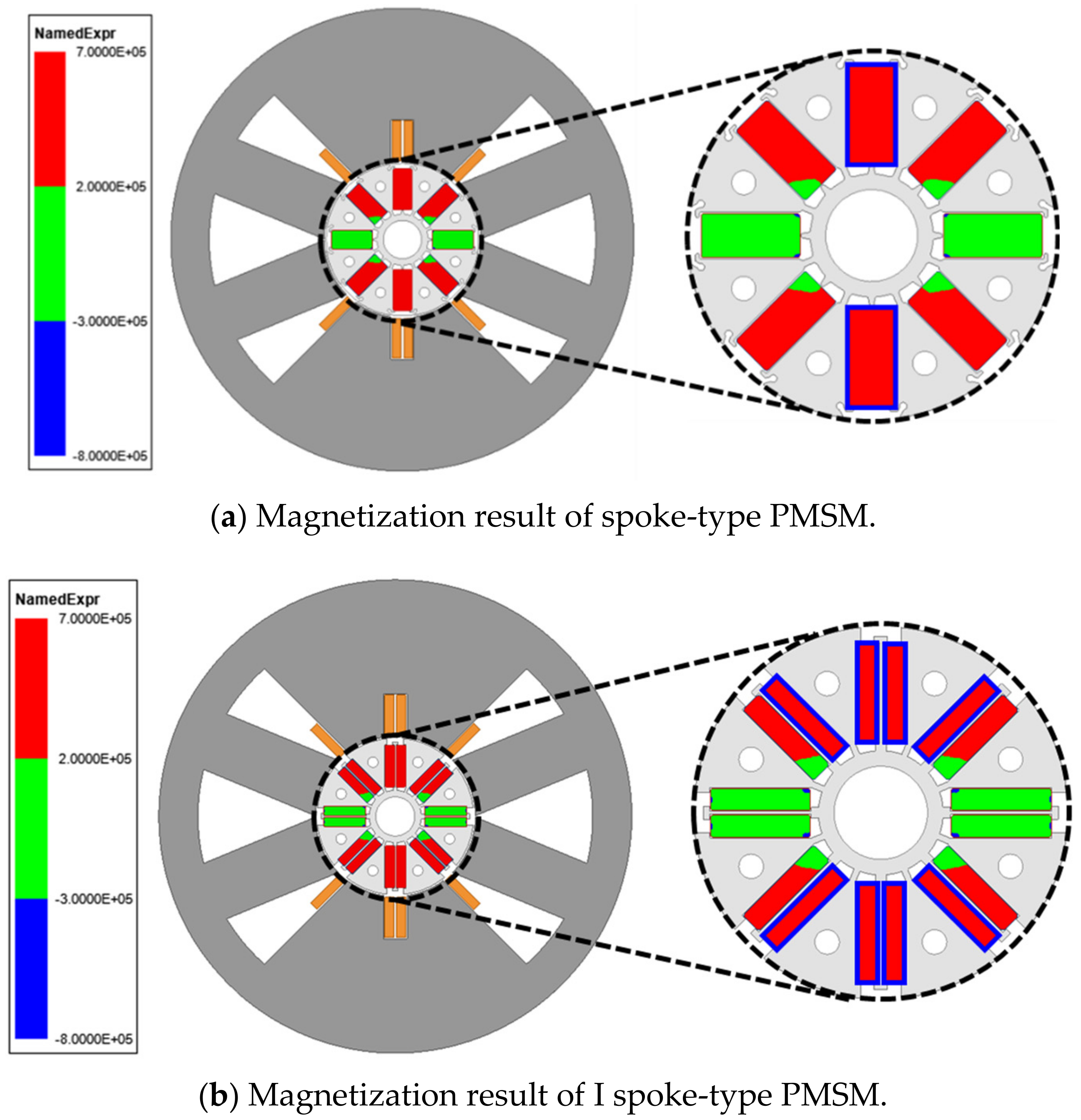
4.3. Magnetization Analysis
First, Figure 19 and Table 6 show the specifications and magnetization system used in the magnetization analysis. Figure 20 is the actual analysis result based on the above analysis conditions. In this figure, the red part shows the magnetized permanent magnet, the green part shows the unmagnetized permanent magnet, and the blue part shows the area where irreversible demagnetization occurred.
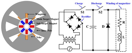
Figure 19.
Magnetizer and magnetizing circuit; (a) configuration of magnetizer; (b) magnetizing circuit.
Table 6.
Magnetizer specification.

Figure 20.
Compare of two types of magnetization result.
As a result of the MEC analysis described above, it indicates that the permanent magnet located in the center of the magnetizing yoke is fully magnetized due to the concentration of the magnetic field. On the other hand, it indicates that the magnetic field of the permanent magnet located in the air layer is relatively reduced, resulting in an unmagnetized area.
As shown in Figure 20, in the case of the conventional spoke-type PMSM, the permanent magnet located in the air layer is not fully magnetized, so it must be placed in the center of the magnetizing yoke to proceed with the magnetization process. However, the I spoke-type PMSM is different from the above case.
In the case of the I spoke type PMSM, unlike the conventional spoke-type PMSM, since it is composed of a structure in which the magnet is divided, the fully magnetized area can be configured as shown in Figure 20b. As a result, in the conventional spoke-type PMSM in Figure 20a, two permanent magnets are fully magnetized when magnetized once based on eight permanent magnets. In order to magnetize all permanent magnets, a total of four magnetization processes are required.
However, the I spoke-type PMSM in Figure 20b has a total of 16 permanent magnets because the magnets are divided, and eight permanent magnets become magnetized once magnetized. Therefore, in order to magnetize all permanent magnets, only a total of two magnetization processes are required, and this reduces the time required for the magnetization process by half compared to the conventional spoke-type PMSM. Therefore, the I spoke-type PMSM structure can improve the magnetization performance after assembly compared to the conventional spoke-type PMSM.
5. Mechanical Stiffness Analysis
In addition to the above-mentioned content, a factor that hinders high-speed operation is the motor stiffness problem. Increasing the speed increases the centrifugal force, which adversely affects the stiffness of the motor. If the stress generated by increasing the speed is higher than the yield strength of the rotor core, it is possible that the rotor may be deformed or the permanent magnet may be scattered.
In other words, the motor should not be considered only for performance and should be designed within the range that satisfies the safety factor. Therefore, in this paper, the target safety factor was set to 1.5 or more, and the I spoke-type PMSM was verified to have a safety factor of 1.5 or more at 18,000 RPM through the stiffness analysis.
When analyzing the structure of the conventional spoke-type PMSM, it indicates that the permanent magnet is supported by very thin ribs. This is to maximize the magnetic torque by reducing the leakage flux, but at the same time acts as a disadvantage in terms of motor stiffness. Therefore, the conventional spoke-type PMSM has limitations in improving the speed of the motor.
In the case of the I spoke-type PMSM, the I-core inserted between the permanent magnets as well as the ribs additionally supports the permanent magnets. Therefore, it is possible to operate at a higher speed compared to the conventional spoke-type PMSM.
Equation (12) is an equation for calculating the safety factor, and Table 7 and Table 8 are the material data used in the stiffness analysis and the result values calculated through the actual stiffness analysis. In general, the electric motor stress is generated by the centrifugal force generated as the rotor rotates, so the analysis was performed after excluding the stator.
Table 7.
Material property value.
Table 8.
Stiffness analysis result.
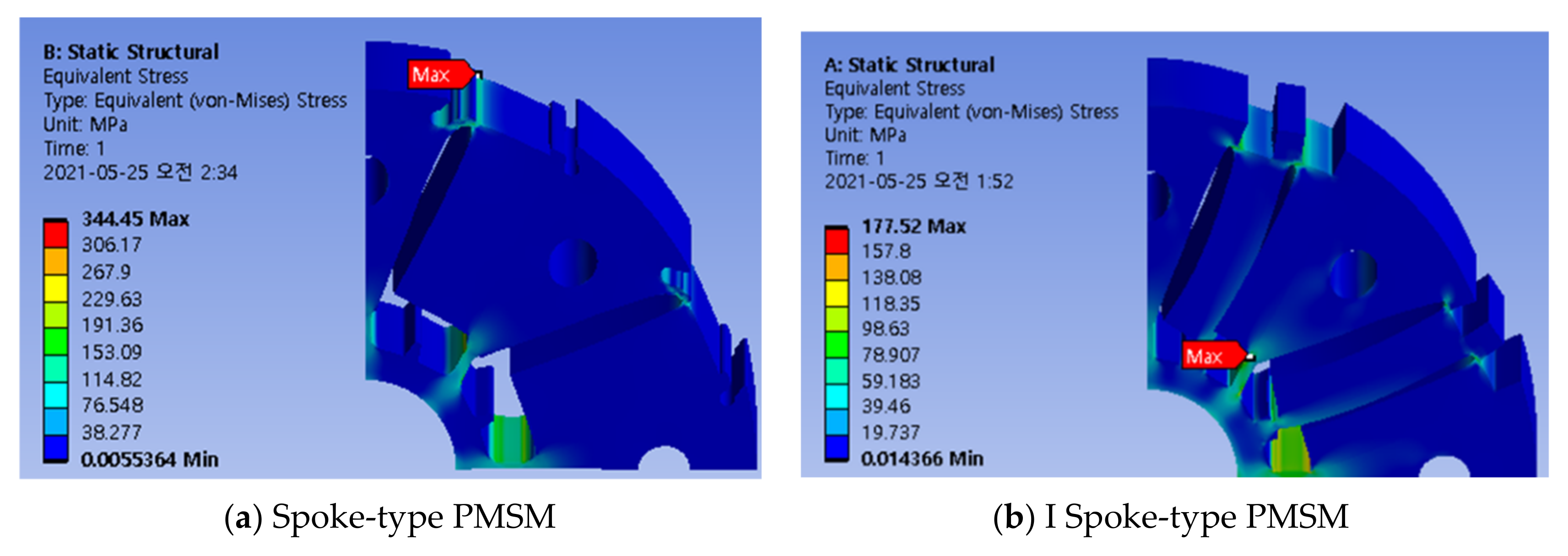
Figure 21 is the result of stiffness analysis when the motor is rotated counterclockwise at the target operating speed of the washing machine, 18,000 RPM. In the conventional spoke type PMSM in Figure 21a, it indicates that the centrifugal force generated as the speed increases is concentrated in the rib located on the left side.

Figure 21.
Stiffness analysis result for each model at 18,000 RPM.
As a result, a very high stress was generated in the rib located at the top of the rotor, and a stress of 344.45 MPa was generated numerically.
On the contrary, the I spoke-type PMSM in Figure 21b has the highest stress in the bridge located at the bottom of the rotor. This is because the I-core located between the existing permanent magnets holds the permanent magnet together, so the stress is not concentrated in one rib, but the stress is distributed to the rib and the I-core.
As a result, the highest stress occurred in the lower bridge of the rotor with weak rigidity, and a stress of 177.52 Mpa was generated numerically.
Table 8 shows the peak stress and safety factor calculated through the stiffness analysis previously. In the case of the conventional spoke-type PMSM, since the safety factor is less than 1, operation at 18,000 RPM is impossible. However, the I spoke-type PMSM has a safety factor of 1.58, so it has more than the target safety factor. Therefore, it indicates that it is possible to operate without problems with the rigidity of the motor at 18,000 RPM.
6. Conclusions
In this paper, a study was conducted on the improvement of hydration performance of spoke-type PMSM applied to washing machines. In order to improve the hydration performance, high-speed operation of the motor is essential, but the conventional model was unable to improve the speed due to problems such as irreversible demagnetization, insufficient torque, and mechanical rigidity. In this paper, the rotor shape of the conventional spoke-type PMSM was modified to solve these problems, and the proposed model showed that the aforementioned problems were effectively solved.
Author Contributions
Conceptualization, W.-H.K.; methodology, M.-J.J.; software, M.-J.J.; validation, M.-J.J.; formal analysis, M.-J.J.; investigation, M.-J.J.; resources, M.-J.J.; data curation, M.-J.J.; writing—original draft preparation, M.-J.J. and K.-B.L.; writing—review and editing, M.-J.J. and K.-B.L.; visualization, H.-J.P.; supervision, D.-W.N. All authors have read and agreed to the published version of the manuscript.
Funding
This work was supported by the Korea Evaluation Institute of Industrial Technology (KEIT) grant funded By the Ministry of Trade, Industry & Energy (MOTIE) (No. 20011495), in part by the Gachon University research fund of 2020 (No. GCU-2020-0845-0007).
Institutional Review Board Statement
Not applicable.
Informed Consent Statement
Not applicable.
Data Availability Statement
Not applicable.
Conflicts of Interest
The authors declare no conflict of interest.
References
- Tahanian, H.; Aliahmadi, M.; Faiz, J. Ferrite Permanent Magnets in Electrical Machines: Opportunities and Challenges of a Non-Rare-Earth Alternative. IEEE Trans. Magn. 2020, 56, 1–20. [Google Scholar] [CrossRef]
- Zhu, X.; Wang, L.; Chen, Y.; Chen, L.; Quan, L. A Non-Rare-Earth Doubly Salient Flux Controllable Motor Capable of Fault-Tolerant Control. IEEE Trans. Magn. 2015, 51, 1–4. [Google Scholar] [CrossRef]
- Chiba, A.; Takano, Y.; Takeno, M.; Imakawa, T.; Hoshi, N.; Takemoto, M.; Ogasawara, S. Torque density and efficiency improvements of a switched reluctance motor without rare-earth material for hybrid vehicles. IEEE Trans. Ind. Appl. 2011, 47, 1240–1246. [Google Scholar] [CrossRef]
- Chiba, A.; Kiyota, K.; Hoshi, N.; Takemoto, M.; Ogasawara, S. Development of a rare-earth-free SR motor with high torque density for hybrid vehicles. IEEE Trans. Energy Convers. 2015, 30, 175–182. [Google Scholar] [CrossRef]
- Bianchi, N.; Bolognani, S.; Bon, D.; Pre, M.D. Rotor flux-barrier design for torque ripple reduction in synchronous reluctance and PM assisted synchronous reluctance motors. IEEE Trans. Ind. Appl. 2009, 45, 921–928. [Google Scholar] [CrossRef]
- Barcaro, M.; Bianchi, N. Interior pm machines using ferrite to replace rare-earth surface PM machines. IEEE Trans. Ind. Appl. 2014, 50, 979–985. [Google Scholar] [CrossRef]
- Fasolo, A.; Alberti, L.; Bianchi, N. Performance comparison between switching-flux and IPM machines with rare-earth and ferrite PMs. IEEE Trans. Ind. Appl. 2014, 50, 3708–3716. [Google Scholar] [CrossRef]
- Morimoto, S.; Ooi, S.; Inoue, Y.; Sanada, M. Experimental Evaluation of a Rare-Earth-Free PMASynRM with Ferrite Magnets for Automotive Applications. IEEE Trans. Ind. Electron. 2014, 61, 5749–5756. [Google Scholar] [CrossRef]
- Obata, M.; Morimoto, S.; Sanada, M.; Inoue, Y. Performance of PMASynRM with Ferrite Magnets for EV/HEV Applications Considering Productivity. IEEE Trans. Ind. Appl. 2014, 50, 2427–2435. [Google Scholar] [CrossRef]
- Lee, S.G.; Bae, J.; Kim, W. A Study on the Maximum Flux Linkage and the Goodness Factor for the Spoke-Type PMSM. IEEE Trans. Appl. Supercond. 2018, 28, 1–5. [Google Scholar] [CrossRef]
- Cho, S.; Ahn, H.; Liu, H.c.; Hong, H.; Lee, J.; Go, S. Analysis of Inductance According to the Applied Current in Spoke-Type PMSM and Suggestion of Driving Mode. IEEE Trans. Magn. 2017, 53, 1–4. [Google Scholar] [CrossRef]
- Lee, S.G.; Bae, J.; Kim, M.; Kim, W. Study on the Improvement of the Correction Coefficient Considering the 3-D Effect of Spoke-Type Permanent-Magnet Synchronous Motor. IEEE Trans. Magn. 2020, 56, 1–5. [Google Scholar] [CrossRef]
- Seol, H.S.; Jeong, T.C.; Jun, H.W.; Lee, J.; Kang, D.W. Design of 3-times magnetizer and rotor of spoke-type PMSM considering post assembly magnetization. IEEE Trans. Magn. 2017, 53, 8208005. [Google Scholar] [CrossRef]
- Kwon, J.; Kwon, B. High-Efficiency Dual Output Stator-PM Machine for the Two-Mode Operation of Washing Machines. IEEE Trans. Energy Convers. 2018, 33, 2050–2059. [Google Scholar] [CrossRef]
- Jin, C.; Jung, D.; Kim, K.; Chun, Y.; Lee, H.; Lee, J. A Study on Improvement Magnetic Torque Characteristics of IPMSM for Direct Drive Washing Machine. IEEE Trans. Magn. 2009, 45, 2811–2814. [Google Scholar]
- Chi, S.; Zhang, Z.; Xu, L. Sliding-Mode Sensorless Control of Direct-Drive PM Synchronous Motors for Washing Machine Applications. IEEE Trans. Ind. Appl. 2009, 45, 582–590. [Google Scholar] [CrossRef]
- Baloch, N.; Kwon, J.; Ayub, M.; Kwon, B. Low-Cost Dual-Mechanical-Port Dual-Excitation Machine for Washing Machine Application. IEEE Access 2019, 7, 87141–87149. [Google Scholar] [CrossRef]
- Zhang, Z.; Xu, H.; Xu, L.; Heilman, L.E. Sensorless direct field-oriented control of three-phase induction motors based on “Sliding Mode” for washing-machine drive applications. IEEE Trans. Ind. Appl. 2006, 42, 694–701. [Google Scholar] [CrossRef]
- Kang, G.-H.; Hur, j.; Nam, H.; Hong, J.-P.; Kim, G.-T. Analysis of irreversible magnet demagnetization in line-start motors based on the finite-element method. IEEE Trans. Magn. 2003, 39, 1488–1491. [Google Scholar] [CrossRef]
- Hitachi metal, Ferrite magnet demagnetization curve. Available online: https://www.automate.org/userAssets/a3/a3Uploads/pdf/Hitachi-Magnet-Handbook.pdf (accessed on 8 May 2021).
- Wang, Q.; Ding, H.; Zhang, H.; Lv, Y.; Guo, H.; Li, L. Study of a Post-Assembly Magnetization Method of a V-Type Rotor of Interior Permanent Magnet Synchronous Motor for Electric Vehicle. IEEE Trans. Appl. Supercond. 2020, 30, 1–5. [Google Scholar] [CrossRef]
- Fu, W.N.; Chen, Y. A Post-Assembly Magnetization Method for a Line-Start Permanent-Magnet Motor. IEEE Trans. Appl. Supercond. 2016, 26, 1–4. [Google Scholar] [CrossRef]
- Hsieh, M.; Lien, Y.; Dorrell, D.G. Post-Assembly Magnetization of Rare-Earth Fractional-Slot Surface Permanent-Magnet Machines Using a Two-Shot Method. IEEE Trans. Ind. Appl. 2011, 47, 2478–2486. [Google Scholar] [CrossRef]
- Dorrell, D.G.; Hsieh, M.; Hsu, Y. Post Assembly Magnetization Patterns in Rare-Earth Permanent-Magnet Motors. IEEE Trans. Magn. 2007, 43, 2489–2491. [Google Scholar] [CrossRef]
- Lee, S.G.; Bae, J.; Kim, W.-H. Design process of spoke-type permanent magnet synchronous motor considering magnetization performance. IEEE Trans. Appl. Supercond. 2020, 30, 1–6. [Google Scholar] [CrossRef]


Publisher’s Note: MDPI stays neutral with regard to jurisdictional claims in published maps and institutional affiliations. |
© 2021 by the authors. Licensee MDPI, Basel, Switzerland. This article is an open access article distributed under the terms and conditions of the Creative Commons Attribution (CC BY) license (https://creativecommons.org/licenses/by/4.0/).