Article

An Eco-Friendly Gas Insulated Transformer Design

1
Department of Electrical and Energy, Vocational High School, Sinop University, Sinop 57000, Turkey
2
Electrical and Electronic Engineering, Faculty of Engineering, Ondokuz Mayis University, Atakum 55139, Turkey
*
Author to whom correspondence should be addressed.
Energies 2021, 14(12), 3698; https://doi.org/10.3390/en14123698
Submission received: 10 May 2021 / Revised: 16 June 2021 / Accepted: 17 June 2021 / Published: 21 June 2021
(This article belongs to the Special Issue State-of-the-Art Energy Related Technologies in Canada 2020-2021)

Abstract

:
Electricity companies around the world are constantly seeking ways to provide electricity more safely and efficiently while reducing the negative impact on the environment. Mineral oils have been the most popular transformer insulation, having excellent electrical insulating properties, but have many problems such as high flammability, significant cleaning problems, and are toxic to fish and wildlife. This paper presents an alternative approach to mineral oil: a transformer design that is clean and provides better performance and environmental benefits. A 50 kVA, 34.5/0.4 kV gas insulated distribution transformer was designed and evaluated using the COMSOL Multiphysics environment. R410A was used as insulation material. R410A is a near-azeotropic mixture of difluoromethane (CH2F2, called R-32) and pentafluoro ethane (C2HF5, called R-125), which is used as a refrigerant in air conditioning applications. It has excellent properties including environmentally friendly, no-ozone depletion, low greenhouse effect, non-explosive and non-flammable, First, the breakdown voltage of the selected gas was determined. The electrostatic and thermal properties of the R410A gas insulated transformer were investigated in the COMSOL environment. The simulation results for the performance of oil and SF6 gas insulated transformers using the same model were compared. The gas-insulated transformer is believed to have equivalent performance and is an environmentally friendly alternative to current oil-based transformers.

1. Introduction

As the importance of electrical energy in modern society increases due to increase in population, increased industrial activity, and the increase in energy consumption from technological developments, research has focused on improved transmission of energy. For efficient transmission, a high voltage must be used; however, there needs to be safety, low maintenance, low fire risk, and protection of the environment [1]. For greatest efficiency and economic reasons, distribution transformers are located as close as possible to the load (consumer).
Currently, most of the transformers used in the electrical distribution industry are filled with mineral oil as it has excellent properties in terms of both electrical insulation and thermal conductivity. Oil-type transformer units are well suited for outdoors but use flammable liquids for cooling. Depending on the conditions of use and the environment of the transformer, oil deterioration occurs over time and it is well-known fact that it relatively reduces the dielectric properties. This situation causes both time and economic losses and additional costs in the transformer manufacturing process. Transformer oils can also contain small particles, moisture and metal parts, which can lead to partial discharges and punctures at low voltage levels in the oil. Oil insulated transformers generally make up almost half of the total weight in power transformers, in this case both manufacturing and shipping costs reach serious numbers. Moreover, the risk of explosion is always present in oil-insulated transformers [2]. Distribution transformers are widely used in areas where people live, such as hospitals, schools, shopping malls, and under buildings; it should be of small size, high power, low maintenance, non-flammable-explosive features. For these reasons, gas insulated transformers hold much potential [3], as they are non-explosive, non-flammable and environment friendly. In addition, materials do not degrade (as with oil), so there is reduced need for maintenance and replacement. This makes them particularly suitable for use with hydro power, and in underground and offshore substations. There is a consequent increasing demand for gas insulated transformers [4].
SF6 (Sulphur hexafluoride) is widely used in high voltage gas insulated switchgear as it has a number of unique properties that make it ideal for this application; high dielectric strength, self-healing and non-toxic properties [5,6,7,8]. However, SF6 is an extremely potent greenhouse gas, with a Global Warming Potential (GWP) that is 23,500 times that of CO2 and a lifetime of 3200 years in the atmosphere [9]. Today around 80% of the annual production of 10,000 tons of SF6 is used in the power industry [10]. There are, therefore, strict controls on the use of SF6, and by 2100, the contribution of SF6 to global warming will be limited to 0.2% [11]. The strict environmental regulations regarding the use of SF6 and high cost of equipment are major factors that are restricting the growth in the use of Gas Insulated Transformers (GIT). There is thus a need to determine alternative gases for use in gas insulated transformers [12] that are reliable, environmentally friendly, efficient and cost-effective [7,8,13,14,15,16].
This study investigates gases that may be used as an alternative for use in gas insulated transformers. It examines gases with insulating characteristics and physicochemical properties similar to SF6 and might replace SF6. However, it is also important that gases do not contribute to global warming or ozone depletion. Details of gases previously studied that are non-toxic, non-flammable, and have no Ozone Depleting Potential (ODP) and low Global Warming Potential, are given in Table 1 [13,17,18].
In the gas insulated transformer, the gas must provide insulation for high electric field strength, cooling, and arc quenching. In addition, the new gas should have low global warming potential and zero ozone depletion potential. C2F6, C3F8 and c-C4F8 do not have a significant advantage over SF6 as they have high GWP. CF4 and C2F6 have very long lifetimes and their dielectric strengths are rather low compared to SF6 and are unsuitable as insulating gases [17,19,20]. Although CF3I, C5F10O, C6F12O and C4F7N have high insulation capacity and dielectric strength, and have an atmospheric lifetime of only a few days, the boiling point is rather high and would result in liquefaction in normal operating conditions. This would require use of a buffer gas, such as oxygen, nitrogen, or carbon dioxide, or a mixture, to ensure a fully gaseous state at the lowest temperature of use [7,10,14]. R134a also has high insulation capacity and dielectric strength, but would require a buffer gas due to its relatively high boiling point [13].
R410A has significantly lower GWP than SF6, shorter atmospheric life, its ODP is zero, and is non-flammable and non-toxic. R410A has a low boiling point (−52.7 °C at 1 bar), allowing its use for medium voltage applications [18].
After this preliminary elimination, SF6 and R410A gas, which is thought to be the closest alternative, were investigated in more detail. Table 2 shows the parameters of SF6 and R410A gas that play an important role in cooling and insulation.
R410A is a near-azeotropic mixture of difluoromethane (CH2F2, called R-32) and pentafluoro ethane (C2HF5, called R-125), which is used as a refrigerant in air conditioning applications [25].
Molecular weight is an important factor affecting system size at given cooling capacity and operating conditions. If the molecular weight of the refrigerant is large, the system is more compact. The molecular weight of SF6 is 146,055 g/mol and it provides better cooling than R410A, which has a value of 72.6 g/mol.
One of the most important parameters is the liquefaction temperature. The insulating power of the gas weakens with low temperature because the pressure of the gas drops and the gas liquefies. To avoid liquid conversion, the gas dielectric must have a low liquefaction temperature. This value is −63 °C in SF6 and −51.58 °C in R410A. Although this difference is not very large, R410A can be reduced by mixing it with buffer gas in certain proportions. The critical temperature is a distinctive temperature value for all gases. The critical temperature value of SF6 is 45.57 °C while the value of R410A is 71.4 °C. Above this temperature, the gas cannot be compressed and liquefied. Therefore, it is better to choose a refrigerant with a high critical temperature in refrigeration systems. Another important parameter is thermal conductivity. Thermal conductivity is the value that shows how much a material transmits heat, and this value is different for each material. A good insulating gas should have high thermal conductivity. SF6 has a value of 11,627 mW/mK and R410A has a value of 13.6 mW/mK. R410A gas has an advantage over the reference gas as its high thermal conductivity allows it to offer good cooling properties. The fact that SF6 has a GWP of 22,800 while R410A is 2000 is one of the main reasons why it is preferred as an insulation material. Atmospheric lifetime is 3200 years for SF6 and 16 years for R410A.
R410A is not flammable in air at temperatures up to 100 °C at atmospheric pressure. But, at higher temperatures, (>250 °C), decomposition products may include Hydrochloric Acid (HCL), Hydrofluoric Acid (HF) and carbonyl halides [23]. SF6 decomposition temperatures up to 300 °C at atmospheric pressure and decomposition products are SF4, S2F10, SOF2, SOF4 and HIFSO2. These gases cause respiratory system damage and lung disease [24,26].
Among other features, R410A is a very good alternative in terms of atmospheric lifetime since SF6 has a high global warming potential. One of the most important properties is the dielectric strength of insulating materials. Under the same conditions in [17], the electric field density of R410A was found to be 0.92 times that of SF6. In this study, it was found to be 0.78 times under non-ideal conditions.
Security, efficiency, environmental friendliness as well as cost are among the distinguishing features of a system. From this point of view, SF6’s price per kg is $8, while the price of R410A provides an advantage with a price of $3. R410A is available at economical cost and its use is expanding rapidly and globally [27]. Considering all these features, it is a better choice as a dielectric material in GIT for a sustainable environment.
This study investigates how distribution transformers can be designed in an economical and environmentally friendly way [18]. Electrostatic and thermal analysis was performed in the COMSOL environment using a model of a 50 kVA, 34.5/0.4 kV, distribution transformer. Properties of the proposed gas including breakdown voltage level, pressure condition, and heat transfer were examined. The same analysis was performed for a transformer with oil and SF6 gas as comparison. The study consists of two parts: determine the breakdown voltage of R410A gas at different electrode gap distances and pressures for the characterization of the gas for use in COMSOL Multiphysics; definition and analysis of the transformer model.

2. Materials and Methods

The study basically consists of two parts. The first part is to determine the breakdown voltages of R410A gas, which we chose as the insulating gas, at different electrode gap distance and pressures. Apart from the catalogue information, this information is also required for the correct identification of the gas in COMSOL Multiphysics. The second stage covers the definition and analysis of a real transformer model as gas insulated.

2.1. Breakdown Voltage Test

AC breakdown voltage was measured using a test cell consisting of a cylindrical plexiglass cell 60 cm in height and 50 cm in diameter, with two 36 mm diameter sphere electrodes as shown in Figure 1, and with Breakdown Voltage (BDV) Tester as shown in Figure 2.
The body of the cell was made from plexiglass with its outer part filled with epoxy resin with 5 cm thickness. Two sphere electrodes were mounted in the cell and fixed to prevent gas leakage; the spheres had radius, r, significantly greater than the distance, d, between the spheres, so r d 1 .
The electrode gap spacing was varied between 0.2 cm and 1 cm using an adjustable screw and mechanical coupling. Brass was preferred as the electrode material as it does not react with the gas and the surface resistance increases in failure conditions. The cell was evacuated to a pressure less than 0.02 atm (1.5 kPa) before being filled with the test gas.

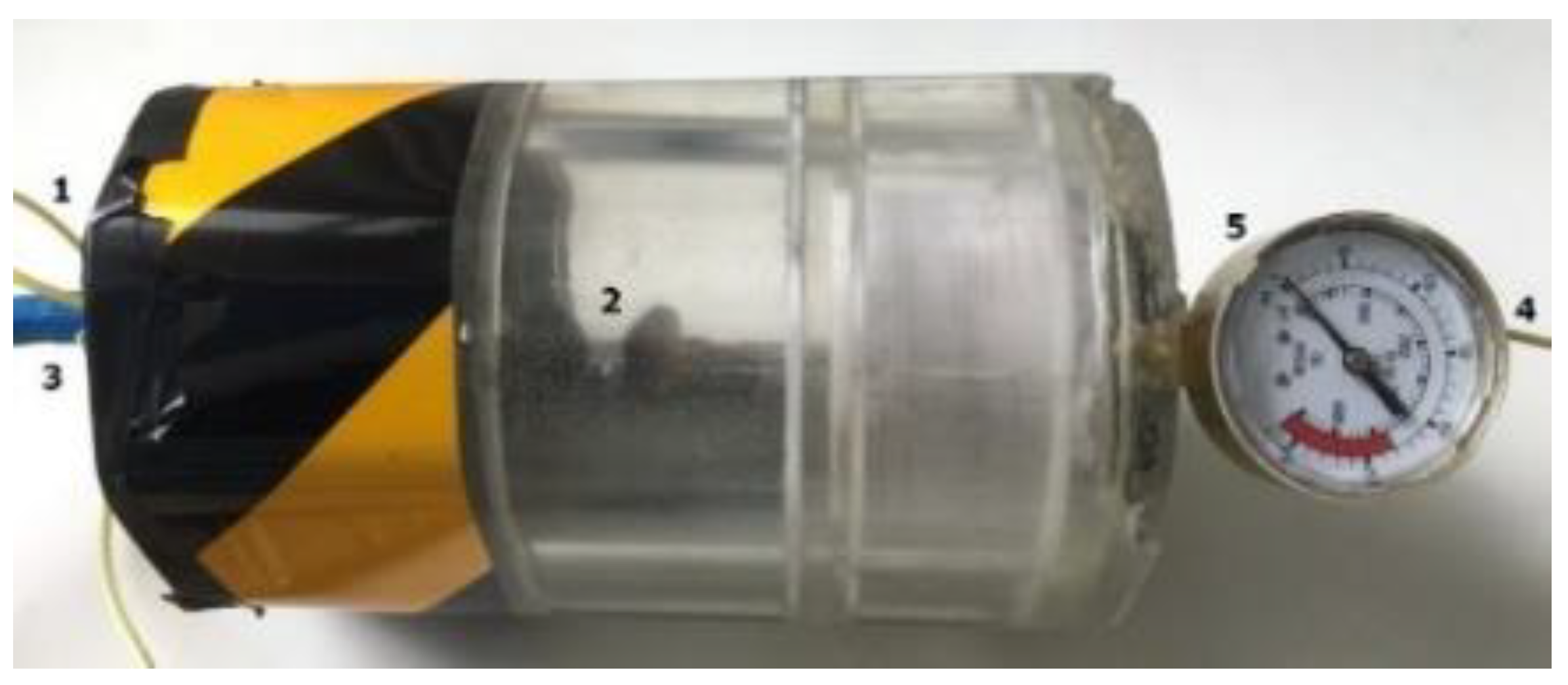
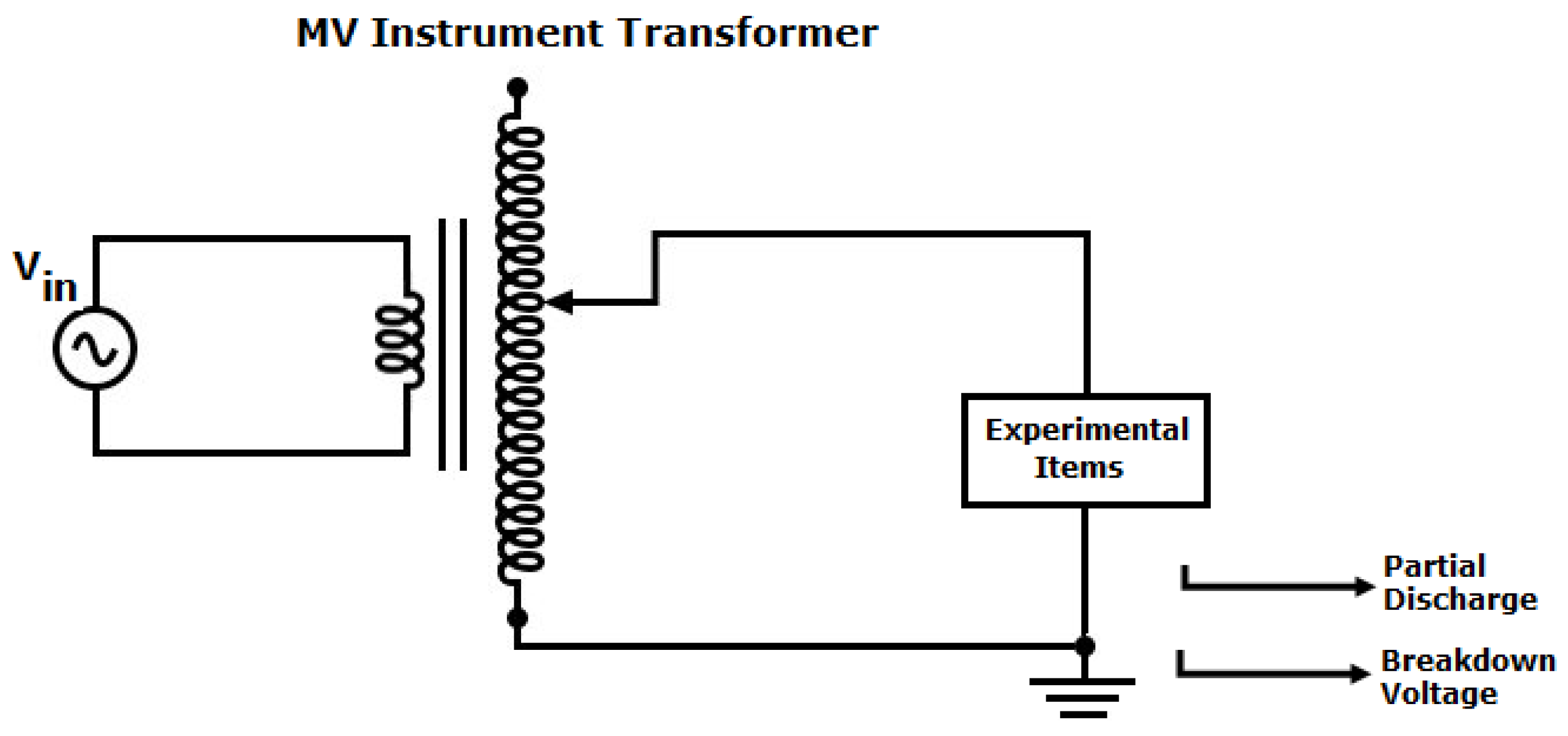
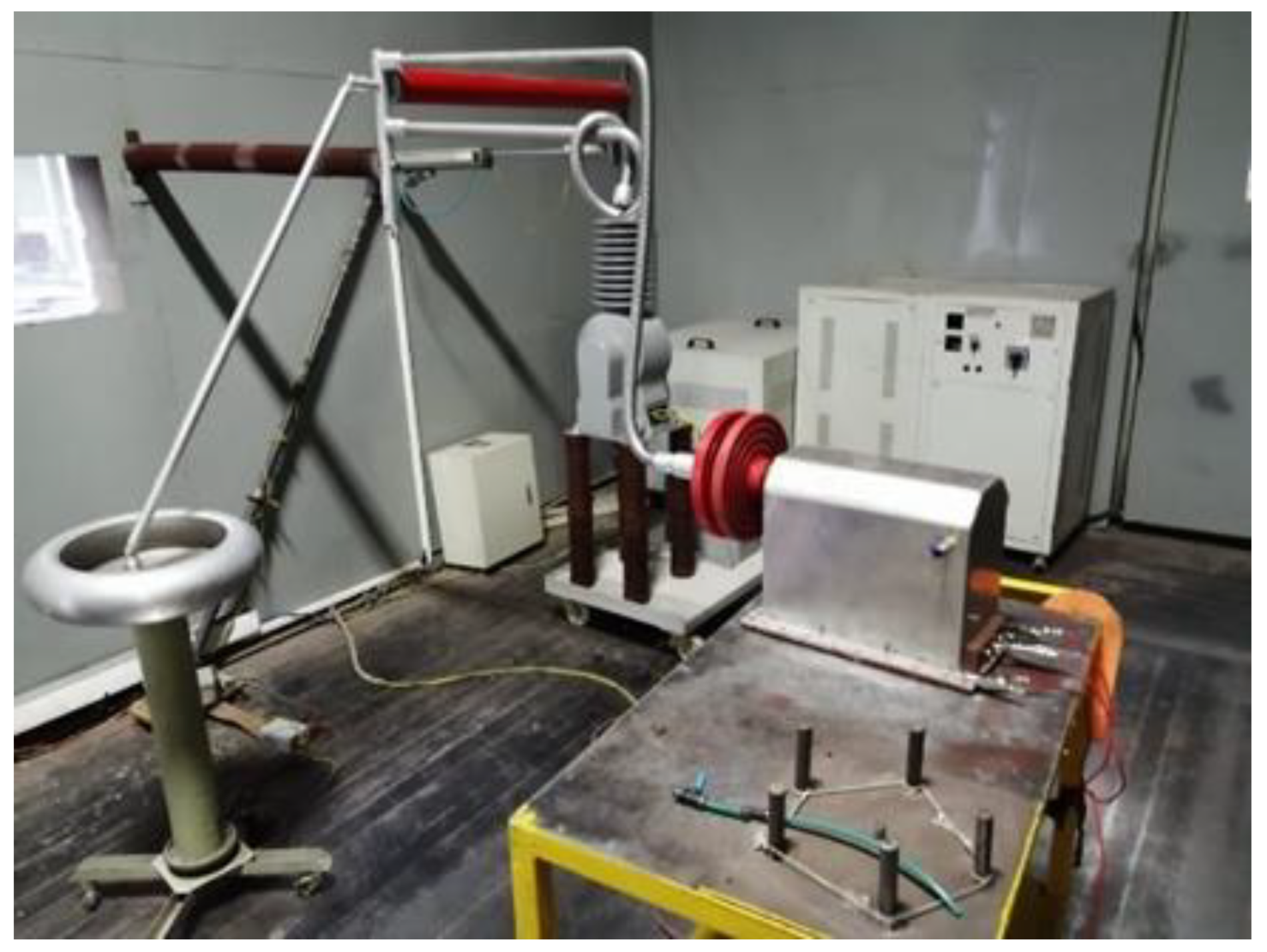
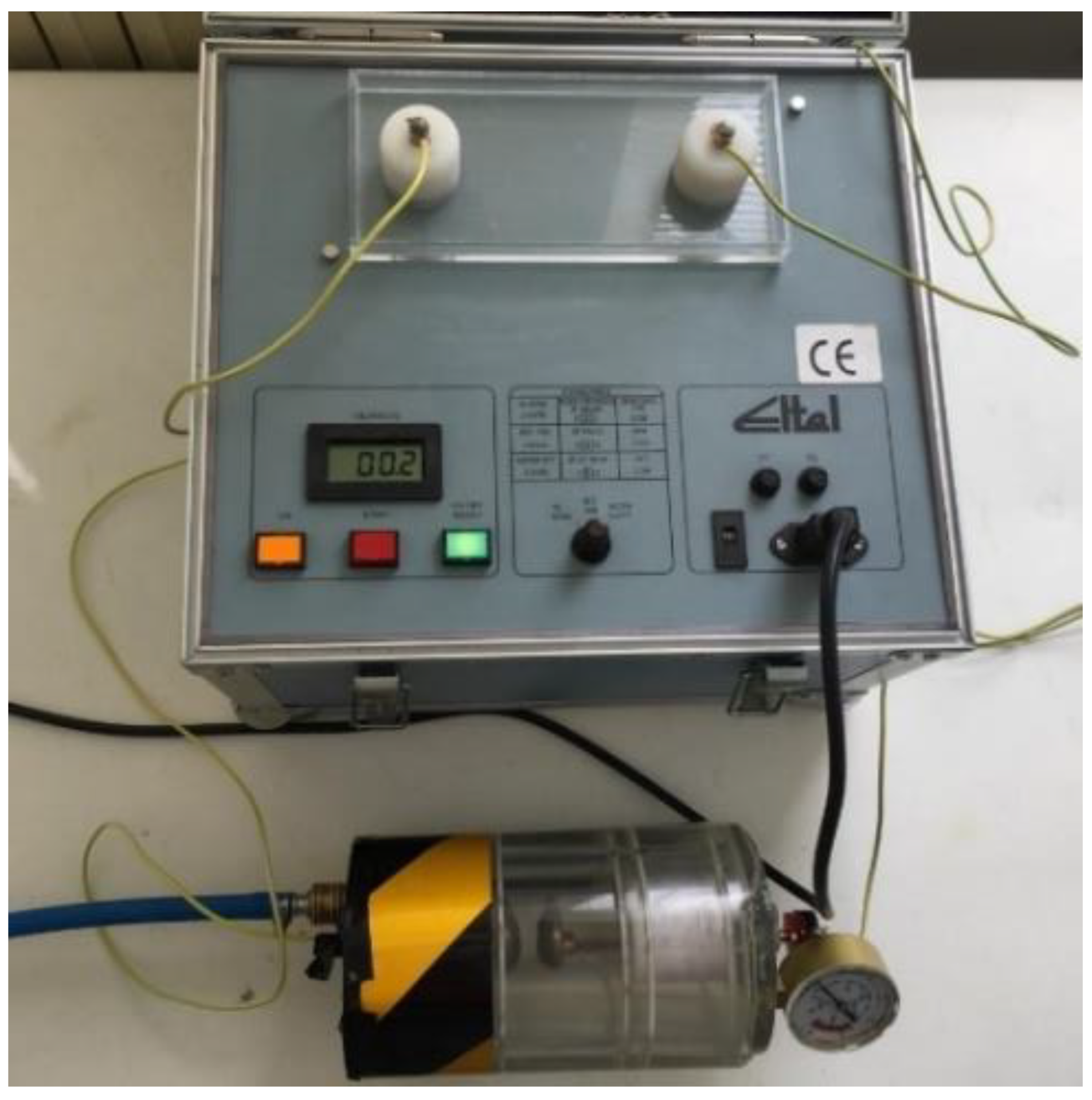
2.1.1. Experimental Setup and Procedure

The tester was designed to measure the dielectric strength of transformer oil and other dielectric fluids according to IEC 156, ASTM 877, and IS-6792, as given in Table 3.
The applied voltage is increased until breakdown occurs between the electrodes in the gap filled with the dielectric fluid. The experimental setup of test cell and breakdown voltage test equipment is shown in Figure 2.
The breakdown voltage of the gas was measured with an electrode system as defined in the IEC 156 standard [28]. The experimental conditions are given in Table 4. Due to the electrodes being mounted rigidly in the test cell, they were not cleaned before an experiment.
Before every set of measurements, the electrode gap was set, and the test cell was vacuumed and filled with the gas under test. The AC voltage was then applied and increased until breakdown occurred. The breakdown voltage was determined for the same electrode gap for pressures from 1 atm to 2.5 atm. The procedure was repeated for each electrode gap. Eight readings were taken and averaged for each pressure and electrode gap. There was a 30-min break between tests to allow the electrodes to cool and minimize the temperature effect of the electrodes.
Figure 3 shows the relationship between breakdown voltage and electrode gap and pressure with R410A as gas. The breakdown voltage increases with pressure and electrode gap, however the relationship is not linear in the range of 0.05 mm to 0.35 mm, but becomes linear above 0.35 mm. R410A conforms to Paschen’s Law for breakdown voltage and pressure over a wide range of pressures, however, deviations are observed at higher pressures under certain conditions [29].

2.1.2. Theoretical Calculation

Townsend Theory and Paschen’s Law can be used to predict the breakdown voltage of a gas at different pressures and electrode separation. Each gas has its own Paschen curve and (pd)min point. The values obtained from the theoretical calculation provide a reference for the accuracy of the experimental results.
In this study (pd)min and (VB)min were determined according to the relations in [29]. Gas breakdown in the presence of a high voltage is described by Paschen’s Law, given by [30]; and as r d 1 then Equation (1) holds.
V b = B p d / ln ( A p d ) ln ( ln ( 1 + 1 γ ) = f ( p , d )
where p is gap pressure, d is electrode gap distance, γ is the secondary electron emission at the cathode, A and B are material constants dependent on the gas. The constants can be determined by experimental measurements or by numerical and analytical calculation [31]. Values of A and B were determined by fitting the curve of the form (1) to the breakdown voltage data. The equations are given in Equation (2).
A =   ( exp ( 1 ) × ln ( 1 / γ ) / ( p d ) m i n , B = ( V B ) m i n / ( p d ) m i n
Brass was used for the electrodes in the experimental setup, and γ was taken as 0.025 [32]. The Townsend first coefficient, α was determined as Equation (3).
α × d = ln ( 1 + 1 / γ )
In a parallel electrode system with no edge effect, the electric field, E, may be determined as Equation (4).
E = V / d
where V is the applied voltage and d is the distance between electrodes. Figure 4 gives the theoretical breakdown voltage Ud = f(p,d) for R410A and SF6 over the pressure range in this study. The values for SF6 were obtained from the formula in [33].
The study in [19] determined that R410A has a dielectric strength that is 0.90–0.92 that of SF6. In this study, the dielectric strength of R410A at low pressure between electrode gaps was found to be 0.78 times that of SF6 and at high dielectric strength approximately 0.69 times.

2.2. R410A Insulation GITs Analysis

2.2.1. Experimental Setup

The performance of R410A as insulation material in a gas insulated transformer was tested using an existing medium voltage instrument transformer (VIT) previously tested with SF6. The wiring diagram for partial discharge test setup is shown in Figure 5.
The experimental setup is shown in Figure 6. The materials used are aluminum, copper, gas, epoxy cast resin, acrylic plastic and soft iron. The model was filled with air, SF6 and R410A, respectively. A partial discharge test was performed for each gas.
The VIT was tested with air, SF6 and R410A to compare the performance of R410A. The partial discharge curves for the three gases are shown in Figure 7.
In the partial discharge test, the applied voltage was increased in 3 kV increments to 1.2 times the rated voltage of the transformer. The transformer was left at each voltage level for 1 min and the partial discharge was then measured. The result should be less than 50 pC for a good insulator. Although this value was exceeded for SF6 and R410A, the results were deemed acceptable. It is expected that air will rise to 100 pC.

2.2.2. Simulation of R410A GIT Model

This paper investigates the design an eco-friendly R410A gas insulation distribution transformer. A model of a widely used 50 kVA 34.5/0.4 kV transformer was studied in a simulation environment.
The R410A GIT model consists of a core, a yoke, HV and LV windings, HV bushings, R410A gas, dielectric barrier (wood), tap changer and sparking gap. The transformer meshed structure is given in Figure 8. Both 3D and 2D axisymmetric results are practically identical. The 2D approximation reduces the computing time, as the number of elements is less. In the transformer model, the high voltage windings and bushings were meshed more finely to achieve greater accuracy.
As the gas performs both insulation and cooling, it must be distributed homogeneously in the tank. For this reason, gas insulated transformers have a cylindrical structure. [30].
For the electrostatic analysis, 3D modeling and a stationary solution has been used. For the heat analysis, a 2D axial model and time-dependent solutions are used. Electrostatic and thermal analyzes were all carried out in COMSOL Multiphysics 5.5.

2.2.3. Electrostatic Analysis

The electrical properties of all the materials used in the design including R410A, wood, copper, soft iron, were defined in the 3D simulation model. In the electric field calculations, the norm of the electric fields E d x ,   E d y ,   E d z is used as in Equation (5).
N o r m ( E ) = E d x 2 + E d y 2 + E d z 2
Figure 9 shows the simulated electric field strength, Ed, for a selected point between the HV winding and the LV winding is lower than the Edmax limit. This is expected and desired.
Analysis of a lightning impulse is also required to determine the worst-case electric field strength.
Figure 10 shows the simulated electric field strength, Ed, exceeds the Edmax limit at the low tank pressure between 0.58 and 0.72 atm.
The potential distribution within the GIT is shown in Figure 11. The tank cover, upper cover and R410A gas units are removed to allow the detail of the voltage distribution within the tank to be visualized.

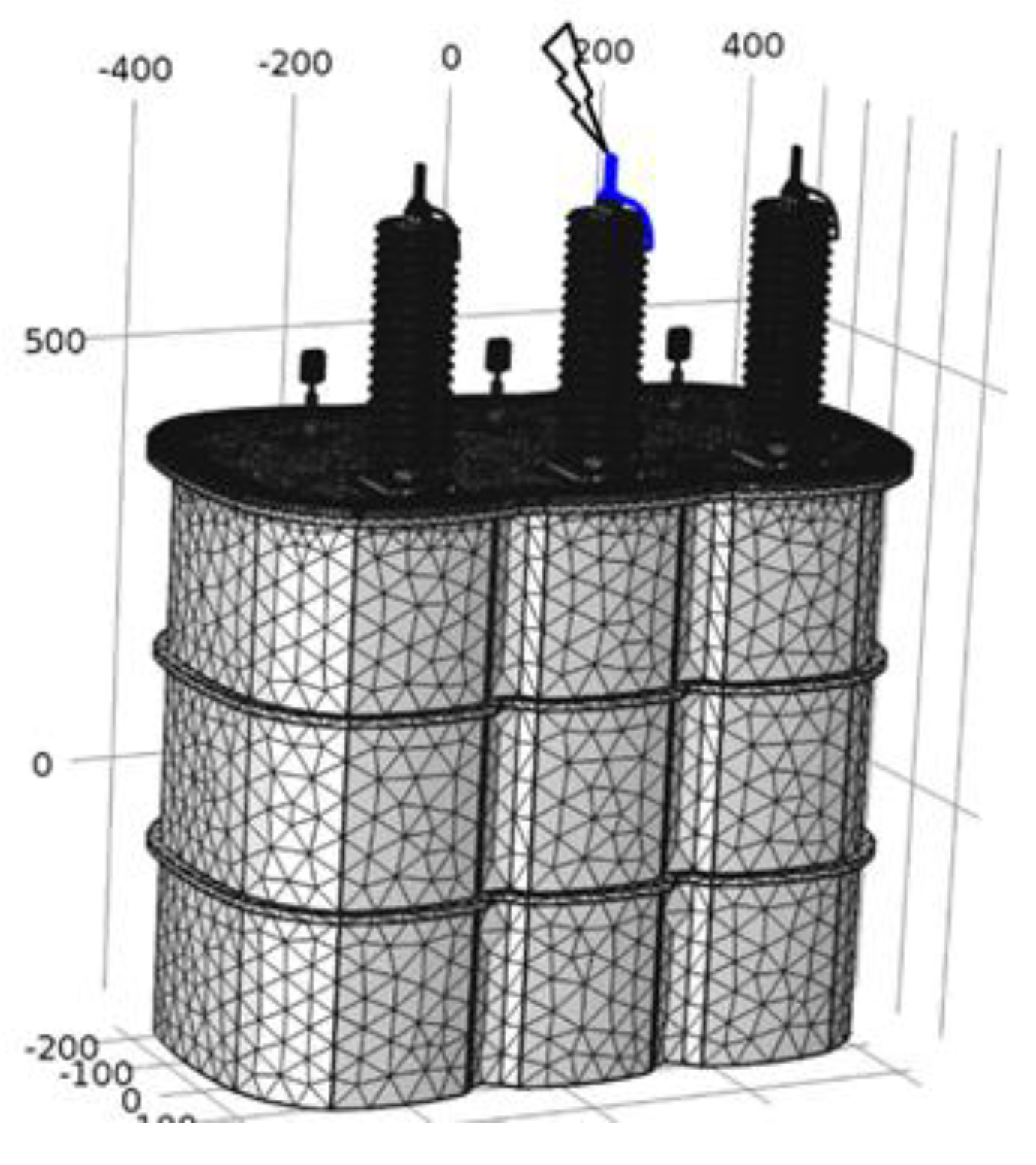
2.2.4. Analysis of Distribution of Lightning Impulse Voltage

Analysis of the lightning impulse voltage is shown in Figure 12.
The standard lightning over-voltage of 1.2–50 μs is modelled from IEC 660076-3 as Equation (6).
V L = 103 , 800 ( e 14 , 600 t e 2 , 469 , 135 t )
A simplified model that omits the tank, upper cover and HV bushings was used to study the lightning impulse voltage, in order to obtain results more quickly due to reduced computational time. Analysis determined the peak potentials within the GIT and the breakdown between the HV winding and selected parts within the transformer. Figure 13 shows the electric potential of the windings at the time of peak voltage.
Figure 14 shows the calculated electric fields at a selected point between the corners of HV and LV windings when lightning impulse is applied.
Figure 14 shows the electric field exceeds the critical value of 77.45 kV/cm above 462 atm.cm, when the R410A gas pressure is 3.19 atm.
IEC standards specify a tank pressure of 3 atm as optimum to withstand lightning impulse voltages in a 50 kV distribution transformer. Figure 15 shows the value of the calculated electric field and the Edmax curve for a SF6 gas pressure of 3 atm.

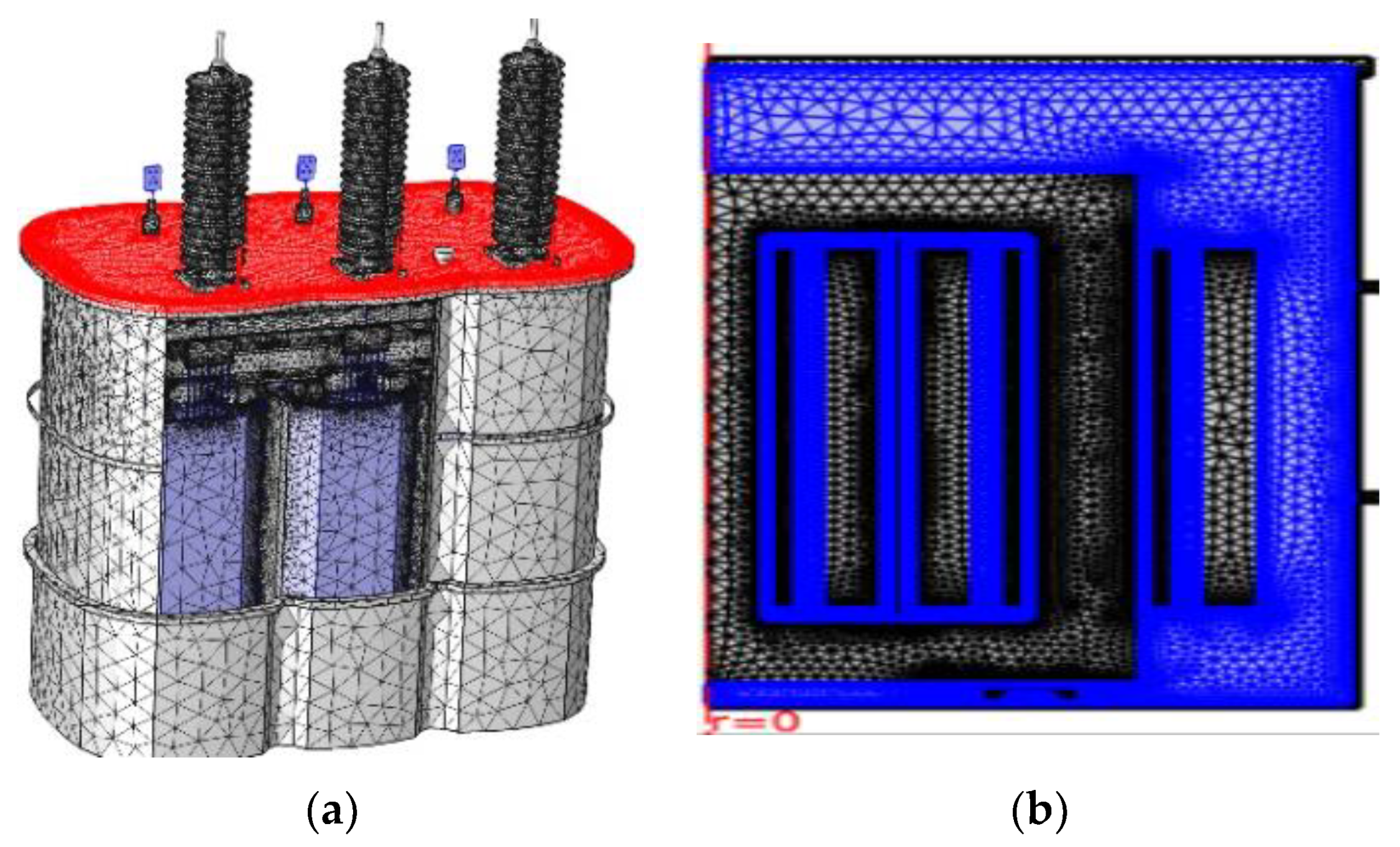
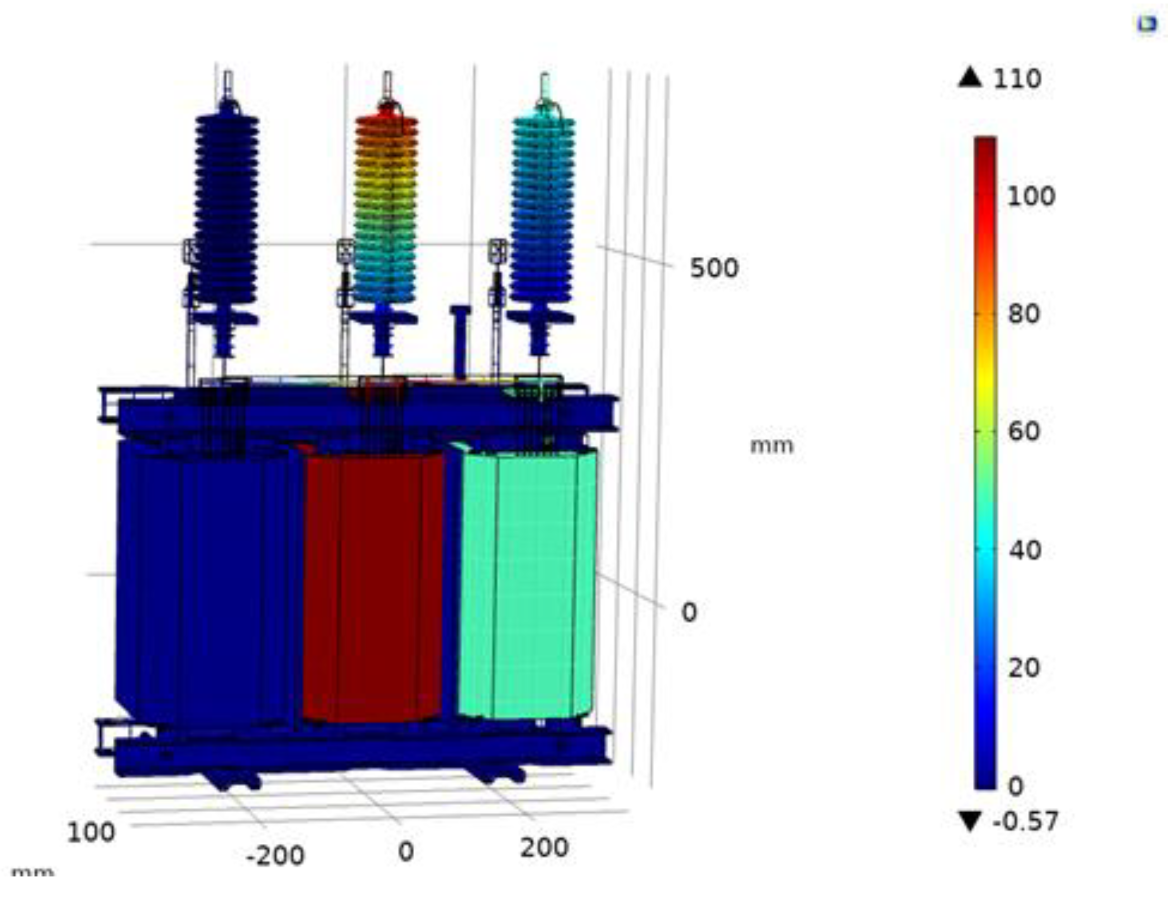
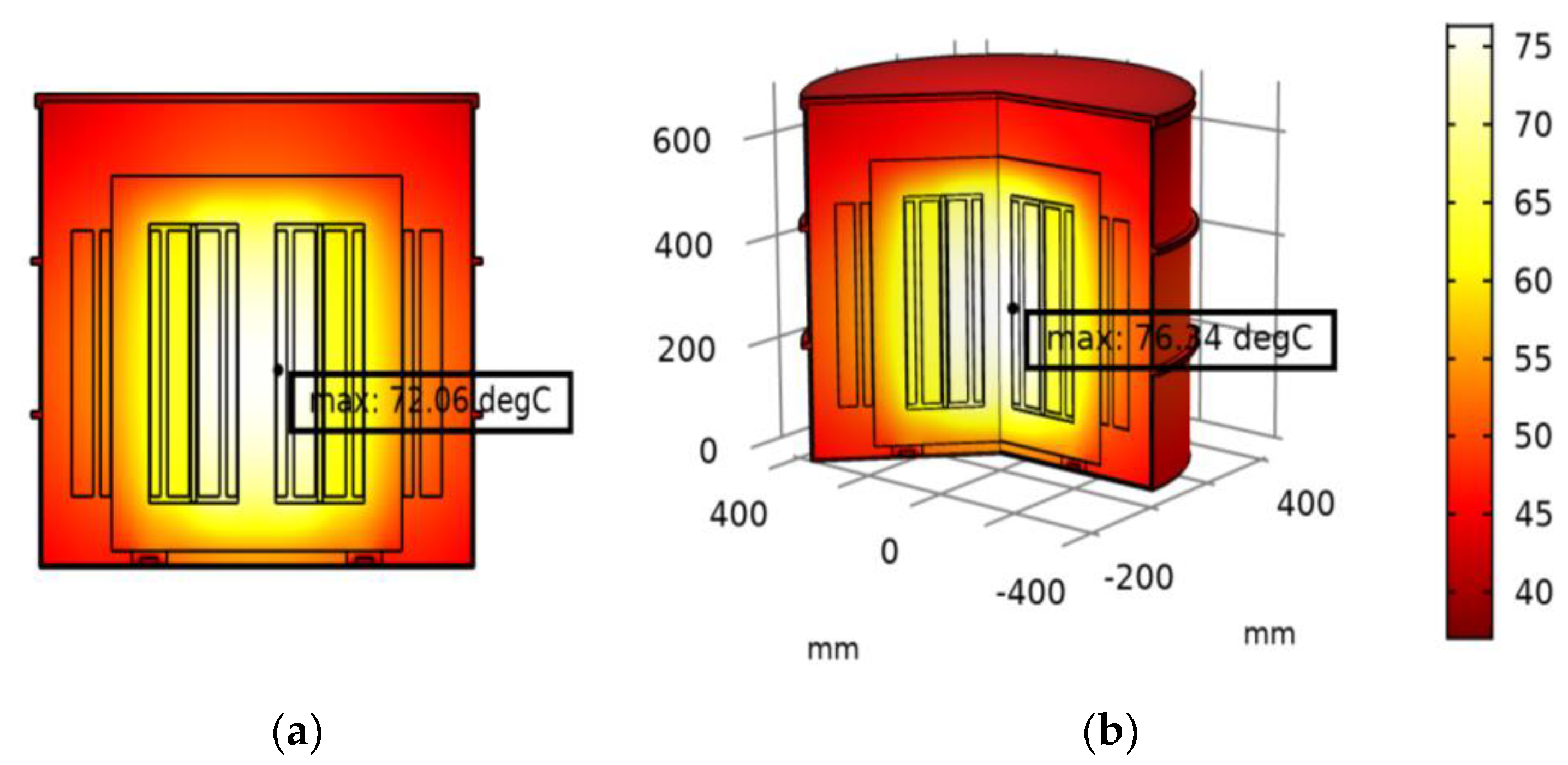
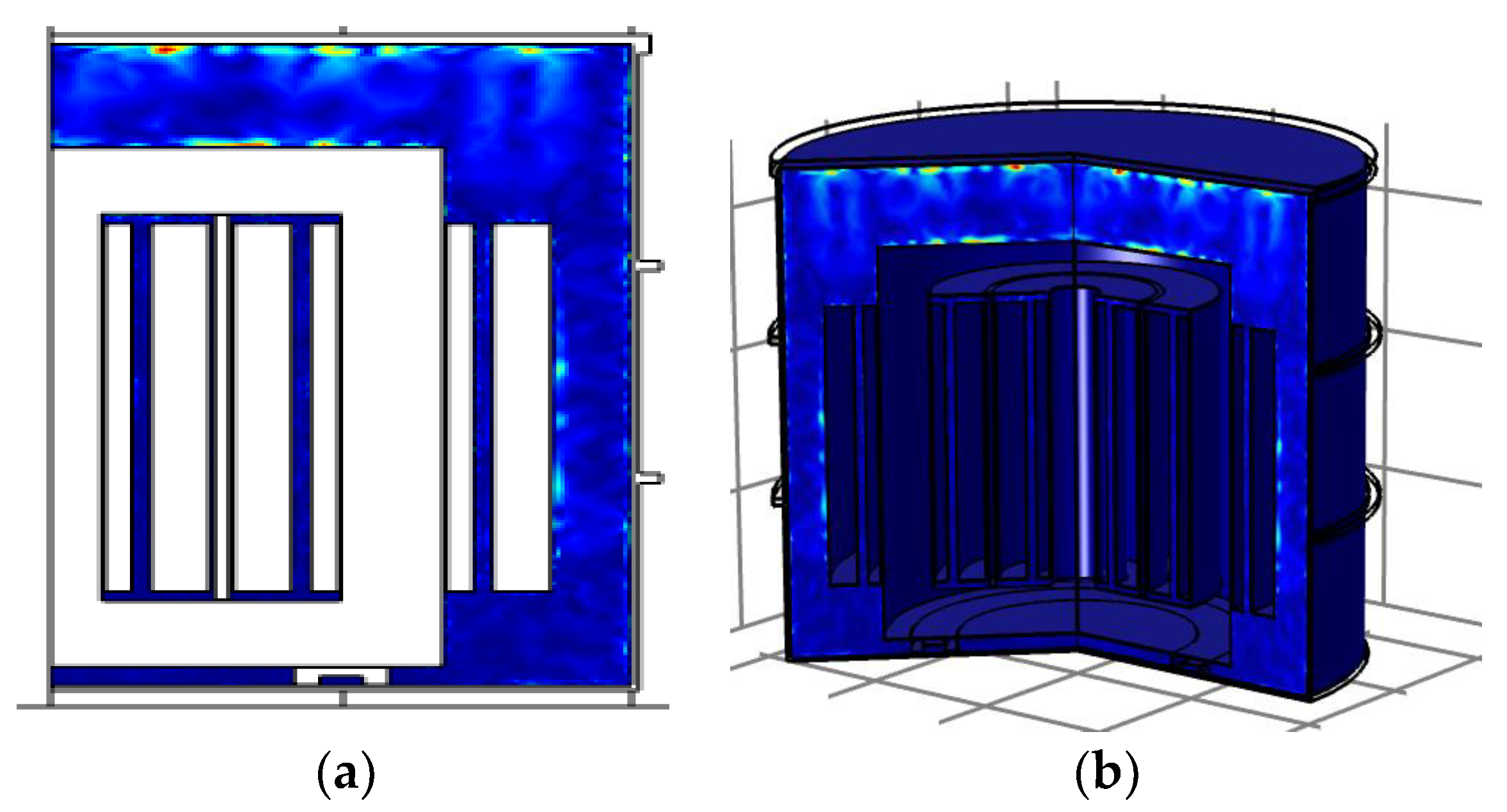
2.2.5. Thermal Analysis of 50 kVA Distribution Transformer

The source of heat in a transformer is primarily due to the current flowing through the winding resistance. A GIT requires a gas that can ensure sufficient transfer of heat from the windings. Thermal analysis can be used to improve performance of the transformer and prevent damage.
Heat analysis of the R410A GIT model was performed on the 2Daxi model with the LV windings being modeled as heat sources. The temperature-dependent equations for the parameters defined for R410A gas are given in Equations (7)–(10).
Thermal conductivity, k [mW/(m*K)]
k = 0.004244 T 2 + 0.01767 T + 12.61
Heat capacity at constant pressure, Cp [kJ/(kg*K)]
C p = ( 1.049 E 7 ) T 3 + ( 2.772 E 6 ) T 2 0.001708 T + 1.915
Density, ρ [kg/m3]
ρ = 41.91 exp ( 0.0244 T ) 12.53   exp ( 0.00895 T )
Dynamic viscosity, μ [mPa*s]
μ = ( 8.489 ) T 2 + 0.005353 T + 12.63
In (7–10), T is temperature in k, p0 is the initial R410A gas pressure, and M R 410 A is the molar mass of R410A where 72.6   ( kJ / kg ) .
The conductive and convective heat transfer within the R410A is given as Equation (11).
ρ C p d T d t + . ( k T ) = ρ C p u . T + P t o t a l
where P t o t a l is the total rated power of R410A GIT. The ambient temperature is defined according to IEEE C.57.12.00. The physical properties of each part of the GIT are shown in Table 5 [33,34].
Figure 16 shows the temperature distribution inside the tank after 2 h. The value for the hot spot temperature is determined as 72.06 °C for 2D analysis and 76.34 °C for 2D axial symmetry analysis. The difference may be explained due to the analysis being determined for the whole region in the 2D analysis but only the axially symmetric half of the region in 2Daxi analysis, and the volumes of gas circulating in the systems are different.
Under the same conditions, the value for the hot spot was found to be 69 °C for SF6 gas insulated transformer and 62.69 °C for oil-insulated transformer in 2D analysis. The results are shown in Figure 17 and Figure 18.
Figure 19 shows the gas velocity at t = 2 h when the system is close to steady state. The heating of the gas by the HV-LV windings causes a decrease in density and the gas rises. Gas at the top is displaced and circulates, establishing a convection pattern, with the gas velocity higher at the top than the bottom.

3. Conclusions

Due to do population and economic growth, global demand for energy is increasing rapidly. And higher consumption of fossil fuels leads to higher greenhouse gas emissions, particularly carbon dioxide (CO2), which contribute to global warming. So, in the changing and polluted world, energy efficiency, efficient use of resources, finding and implementing solutions that will cause the least harm to the environment have become a necessity. This plays an even more important role as distribution transformers are widely used and positioned closest to the load (consumer points). Crowded city centers necessitated the establishment of transformer rooms in smaller areas. As a result of these needs, the development process of gas insulated transformers has started.
This study investigates the design of an environment friendly, efficient and cost-effective gas insulated transformer. SF6 has been widely used as an insulating gas medium in various electrical equipment due to its excellent insulation and arc extinguishing properties. However, SF6 is now known as an extremely strong greenhouse. Therefore, new eco-friendly alternative for replacing SF6 has been researched. The main properties of insulation gases and potential candidates have been discussed. The R410A was chosen among many alternative gases. Because, its parameters that play an important role in insulation and cooling are close to SF6 properties, as well as its low GWP and atmospheric lifetime. Although, there are alternative refrigerants to R410A in the literature, there were no generally accepted alternatives for use in commercial air conditioning systems. R410A use is expanding globally and rapidly. Also, previous research suggests R410A gas has the potential to be an effective insulator in high voltage applications, with similar performance to transformers filled with oil and SF6.
In this study, a R410A gas insulated distribution transformer has been modeled and the electrostatic and heat transfer performance has been simulated in COMSOL Multiphysics 5.5 in order to determine performance. Performance was compared with oil and SF6. Considering the physical properties, the following conclusions can be interpreted through laboratory tests and computer simulations:
(1)
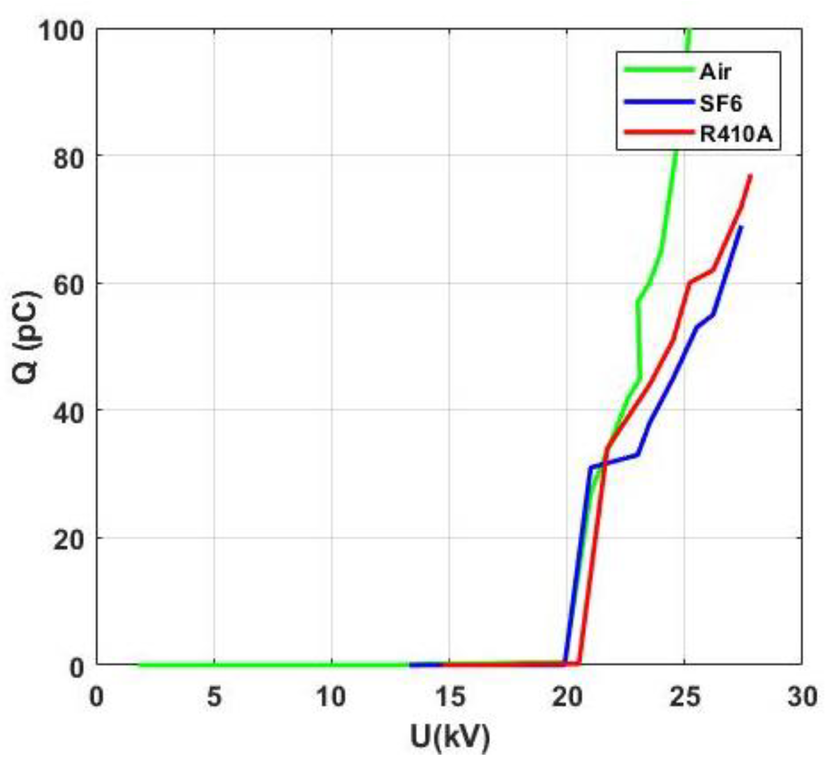
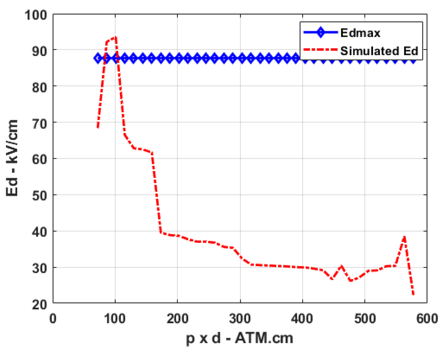
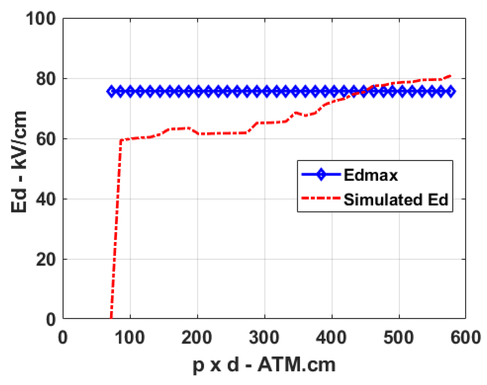
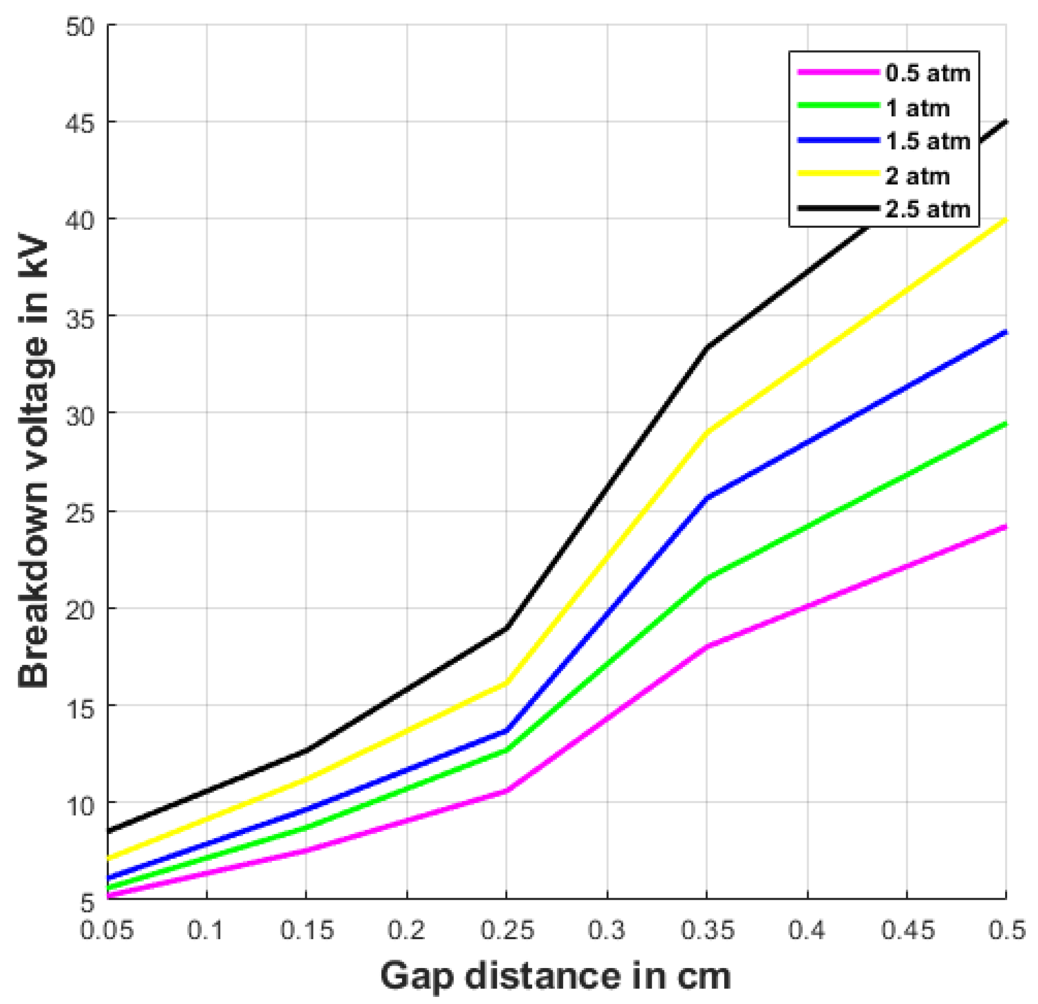
The pure R410A dielectric strength nearly 0.78 times of SF6 under non-ideal conditions. The insulation strength of R410A can reach more than 96% of SF6 with buffer gases. In this case, attention should also be paid to the GWP values.
(2)
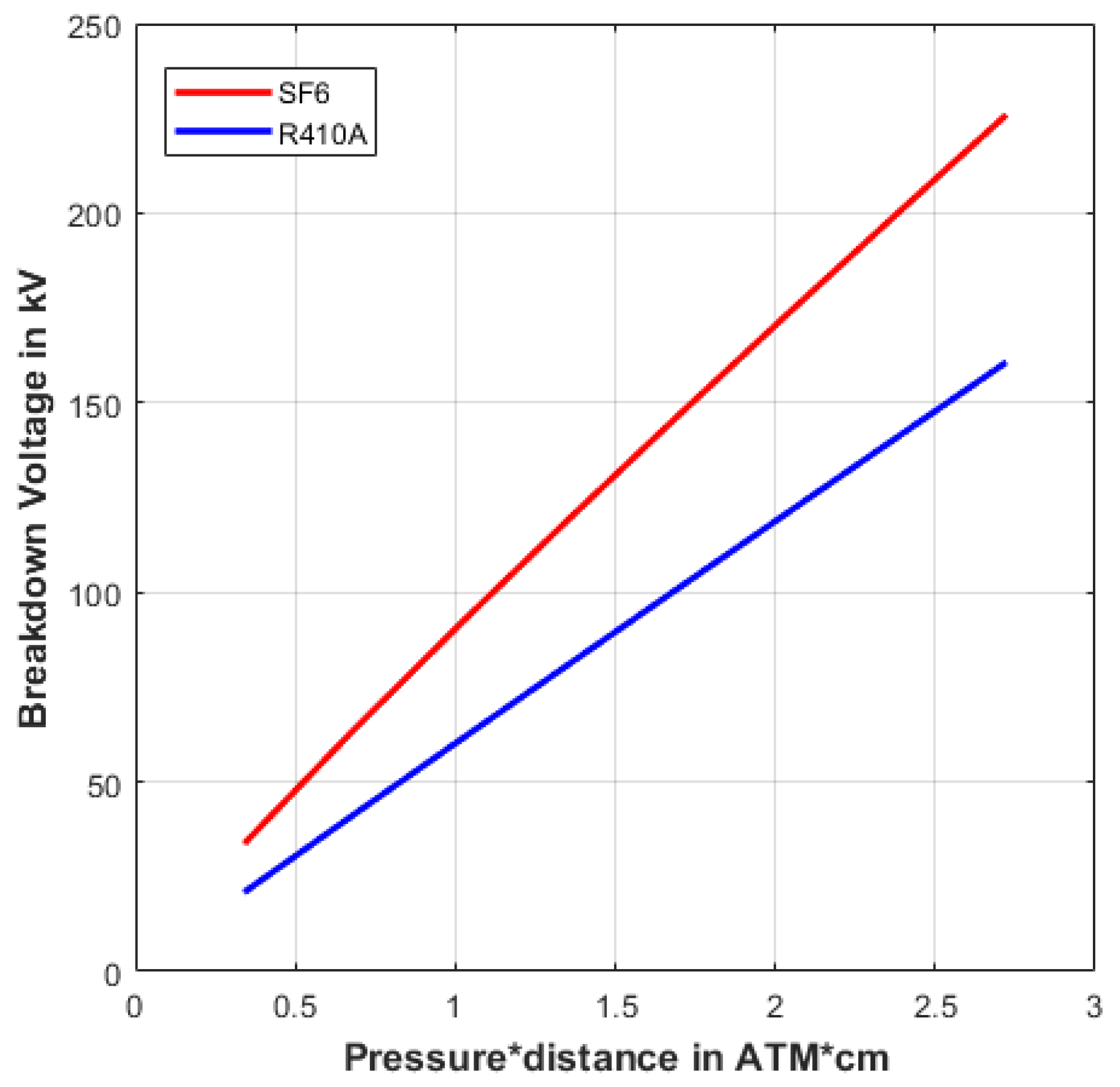
The AC breakdown voltages of R410A increase linearly by increasing the gap length. The proposed gas demonstrates good dielectric properties.
(3)
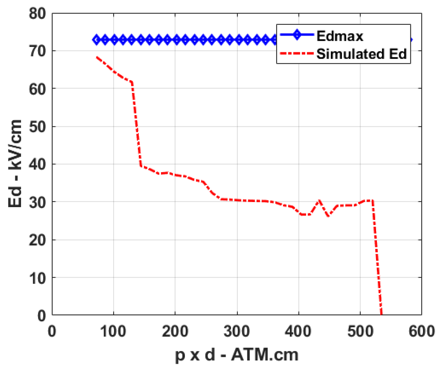
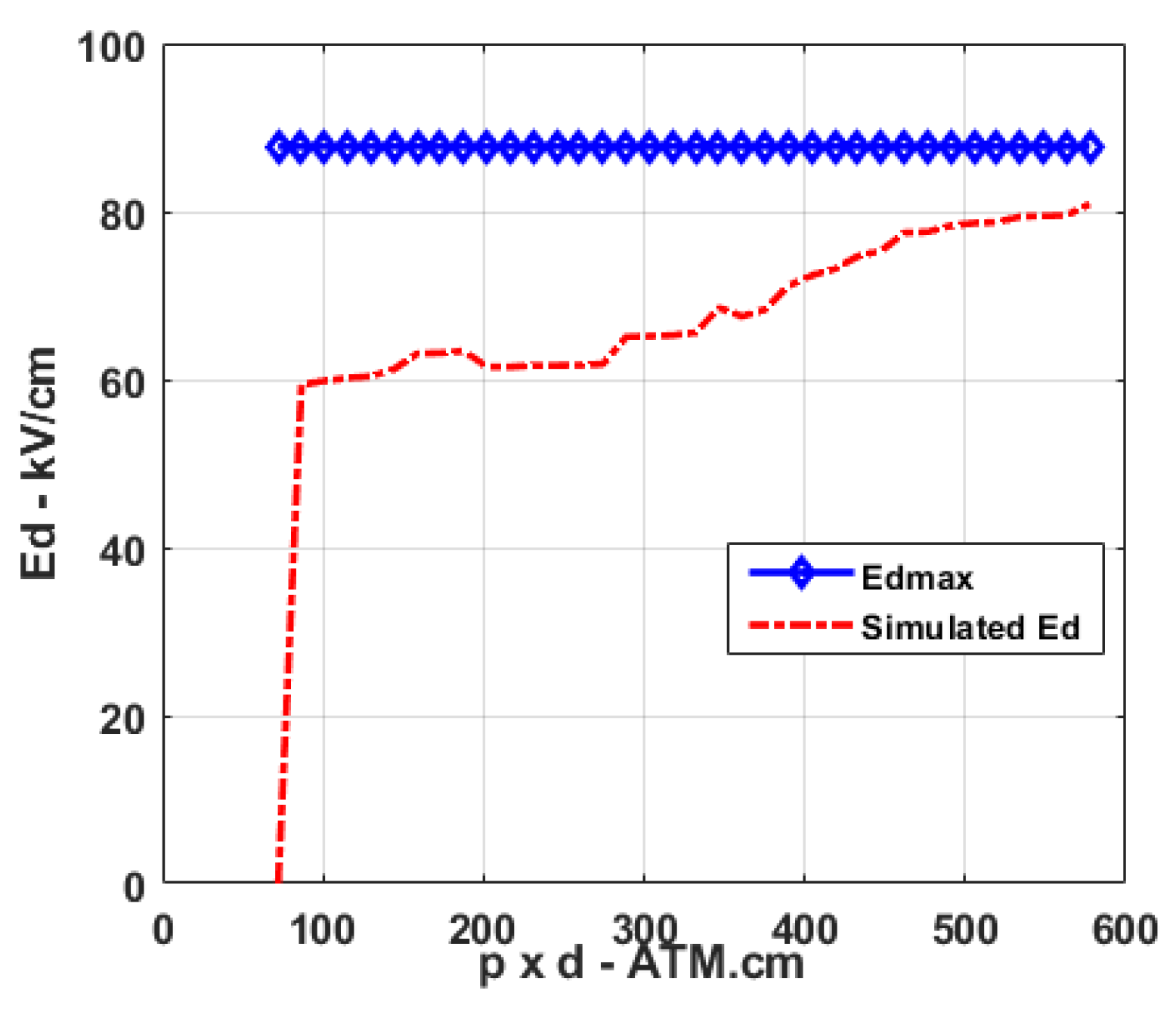
Both electrostatic analysis and lightning impulse voltage analysis results show that the tank pressure for SF6 and R410A is nearly 3 atm.
(4)
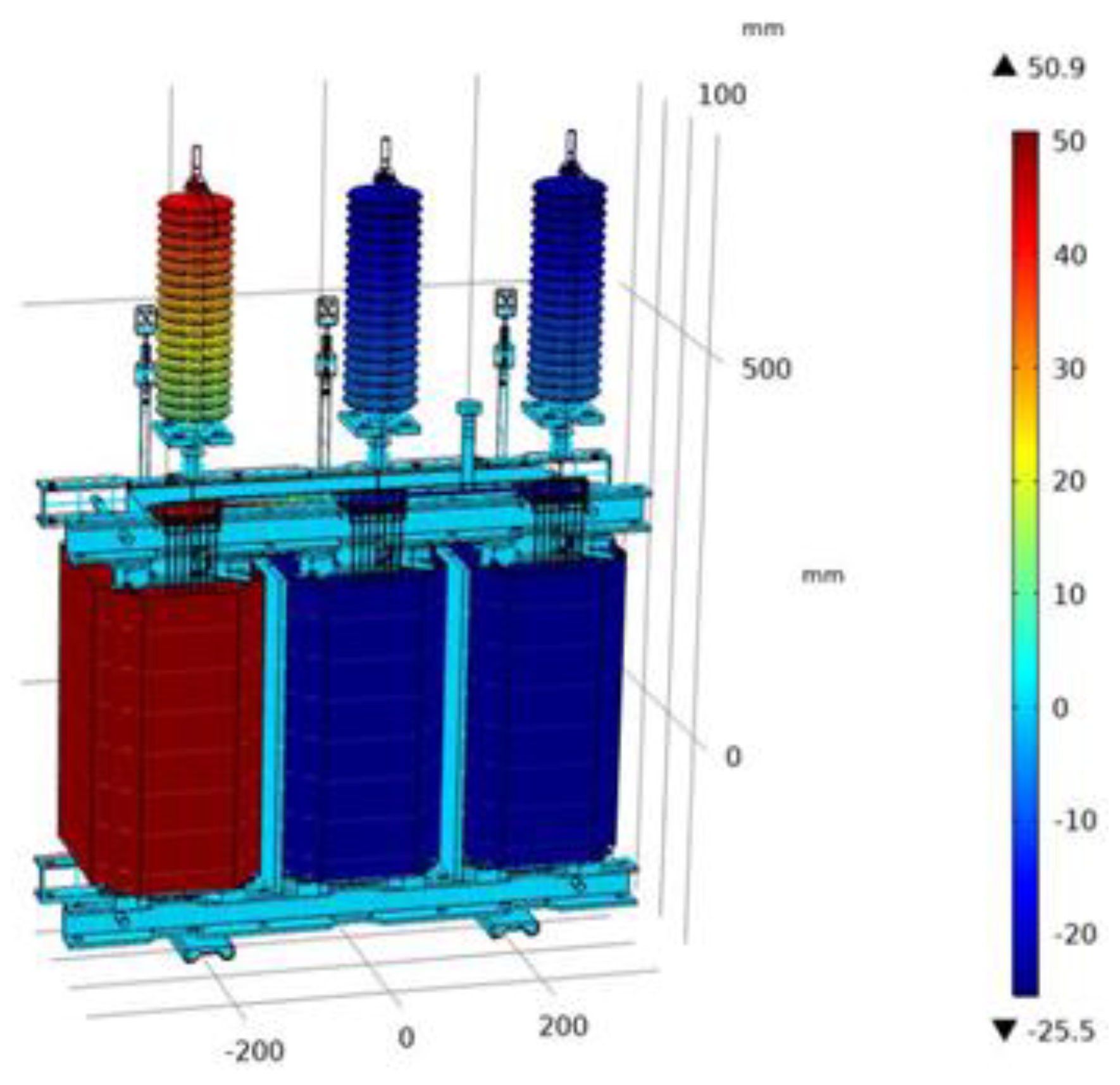
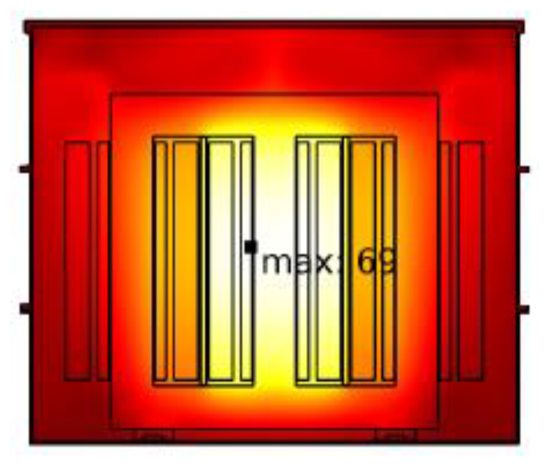
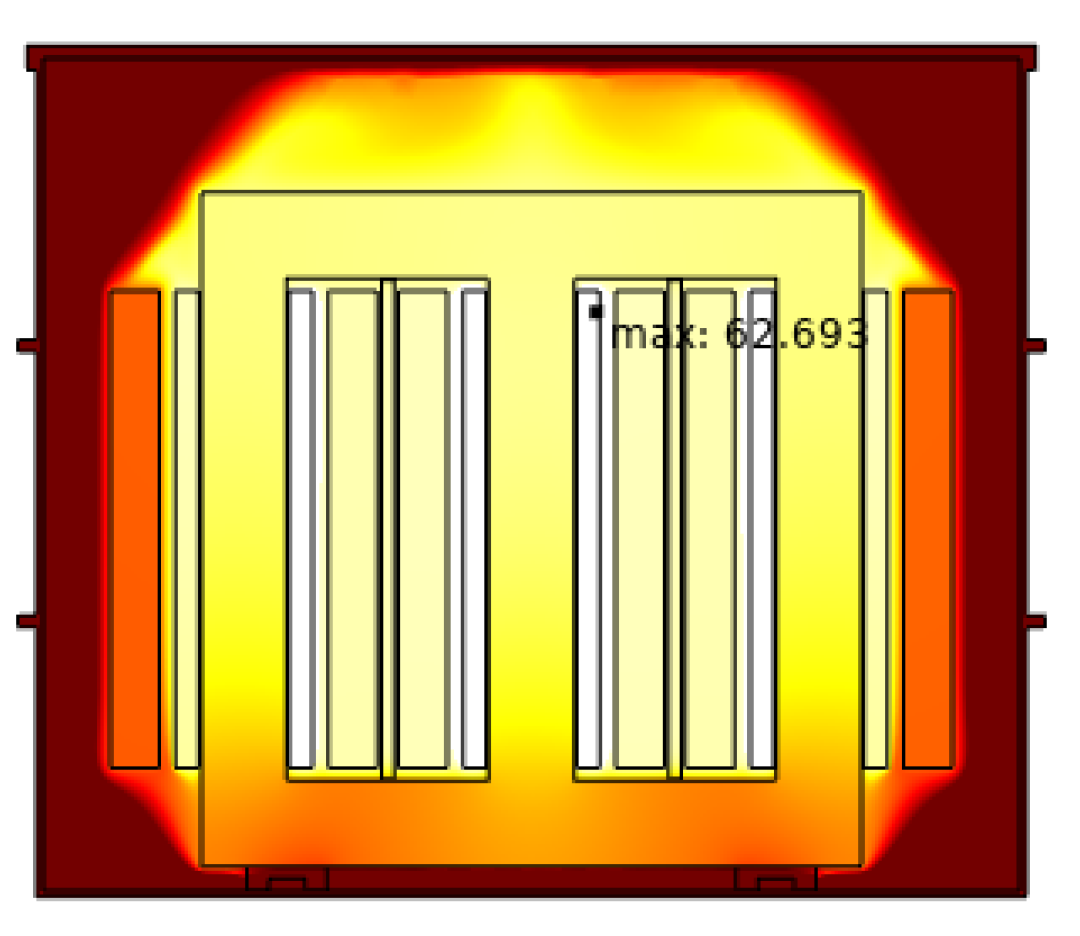
Temperature distribution (hot points) inside the tank was found respectively 62.69 °C, 69 °C, 72.06 °C for oil, SF6 and R410A. From these outcomes, it can be deduced that, the use of R410A has nearly same potential over SF6 and transformer oil.
(5)
Furthermore, these mixture gasses are cost-effective, eco-friendly and reduce the amount of GWP nearly 90% as compared to pure SF6.
The simulation results show the R410A insulated transformer compares well with SF6 and oil, and has a strong potential as an insulator given it is environmentally friendly, cheap and low-maintenance. The authors believe that this study provides the necessary prior knowledge to design and manufacture R410A gas insulated transformers.

Author Contributions

Data curation, O.O.; investigation, E.G.; methodology, O.O.; software, O.O.; writing—original draft preparation, E.G.; writing—review and editing, O.O. All authors have read and agreed to the published version of the manuscript.

Funding

This research received no external funding.

Acknowledgments

The authors are deeply grateful to ESITAS ELEKTRIK for its support for this project. The GIS experimental setup was provided by them.

Conflicts of Interest

The authors declare no conflict of interest.

References

  1. Doukas, H.; Karakosta, C.; Flamos, A.; Psarras, J. Electric power transmission: An overview of associated burdens. Int. J. Energy Res. 2010, 35, 979–988. [Google Scholar] [CrossRef]
  2. Fofana, I. 50 years in the development of insulating liquids. IEEE Electr. Insul. Mag. 2013, 29, 13–25. [Google Scholar] [CrossRef]
  3. Panwar, N.L.; Kaushik, S.C.; Kothari, S. Role of renewable energy sources in environmental protection: A review. Renew. Sustain. Energy Rev. 2011, 15, 1513–1524. [Google Scholar] [CrossRef]
  4. Toda, K. Structural features of gas insulated transformers. In Proceedings of the IEEE/PES Transmission and Distribution Conference and Exhibition, Institute of Electrical and Electronics Engineers, Dallas, TX, USA, 7–12 September 2003; IEEE: Dallas, TX, USA, 2003; Volume I, pp. 508–510. [Google Scholar]
  5. Bolotinha, M. Gas-insulated transformer. Transformers Magazine, January 2018. [Google Scholar]
  6. Eves, M.; Kilpatrick, D.; Edwards, P.; Berry, J. A Literature Review on SF6 Gas Alternatives for Use on The Distribution Network; Western Power Distribution: Wales, UK, 2018; pp. 6–39. [Google Scholar]
  7. Li, Y.; Zhang, X.; Zhang, J.; Xiao, S.; Xie, B.; Chen, D.; Tang, J. Assessment on the toxicity and application risk of C4F7N: A new SF6 alternative gas. J. Hazard. Mater. 2019, 368, 653–660. [Google Scholar] [CrossRef] [PubMed]
  8. Kieffel, Y.; Irwin, T.; Ponchon, P. Green gas to replace SF6 in electrical grids. IEEE Power Energy Mag. 2016, 14, 32–39. [Google Scholar] [CrossRef]
  9. Kyoto Protocol to The United Nations Framework Convention on Climate Change, United Nations, Kyoto, Japan. 1998. Available online: https://www.gegridsolutions.com/hvmv_equipment/catalog/g3/ (accessed on 9 March 2021).
  10. Xiao, A.; Owens, J.G.; Bonk, J.; Zhang, A.; Wang, C.; Tu, Y. Environmentally friendly insulating gases as SF6 alternatives for power utilities. In Proceedings of the 2nd International Conference on Electrical Materials and Power Equipment (ICEMPE), Guangzhou, China, 7–10 April 2019; pp. 42–48. [Google Scholar]
  11. Polvani, L.M.; Abalos, M.; Garcia, R.; Kinnison, D.; Randel, W.J. Significant weakening of Brewer-Dobson circulation trends over the 21st century as a consequence of the Montreal Protocol. Geophys. Res. Lett. 2018, 45, 401–409. [Google Scholar] [CrossRef] [Green Version]
  12. Gas Insulated Transformer Market by Type, Voltage, Installition, End-User, and Region-Global Forecast to 2023, Markets and Markets. 2018. Available online: https://www.marketsandmarkets.com/Market-Reports/gas-insulated-transformer-market-175735946.html (accessed on 9 March 2021).
  13. Ullah, R.; Ullah, Z.; Haider, A.; Amin, S.; Khan, F. Dielectric properties of tetrafluoroethane (R134) gas and its mixtures with N2 and air as a sustainable alternative to SF6 in high voltage applications. Electr. Power Syst. Res. 2018, 163, 532–537. [Google Scholar] [CrossRef]
  14. Xiao, S.; Zhang, X.; Tang, J.; Liu, S. A review on SF6 substitute gases and research status of CF3I gases. Energy Rep. 2018, 4, 486–496. [Google Scholar] [CrossRef]
  15. Kieffel, Y.; Biquez, F.; Ponchon, P. Alternative gas to SF6 for use in high voltage switchgears: G3. CIRED Pap. 2015, 230. [Google Scholar]
  16. Xiao, D. Development Prospect of Gas Insulation Based on Environmental Protection. In Simulation and Modelling of Electrical Insulation Weaknesses in Electrical Equipment; IntechOpen: London, UK, 2018; pp. 79–102. [Google Scholar]
  17. Wang, Y.; Huang, D.; Liu, J.; Zhang, Y.; Zeng, L. Alternative environmentally friendly insulating gases for SF6. Processes 2019, 7, 216. [Google Scholar] [CrossRef] [Green Version]
  18. Khan, B.; Saleem, J.; Khan, F.; Faraz, G.; Ahmad, R.; Ur Rehman, N.; Ahmad, Z. Analysis of the dielectric properties of R410A Gas as an alternative to SF6 for high-voltage applications. High Volt. 2019, 4, 41–48. [Google Scholar] [CrossRef]
  19. Beroual, A.; Haddad, A.M. Recent advances in the quest for a new insulation gas with a low impact on the environment to replace sulfur hexafluoride (SF6) gas in high-voltage power network applications. Energies 2017, 10, 1216. [Google Scholar] [CrossRef] [Green Version]
  20. Kharal, H.S.; Kamran, M.; Ullah, R.; Saleem, M.Z.; Alvi, M.J. Environment-Friendly and Efficient Gaseous Insulator as a Potential Alternative to SF6. Processes 2019, 7, 740. [Google Scholar] [CrossRef] [Green Version]
  21. Koch, D. SF6 properties, and use in MV and HV switchgear. Cah. Tech. 2003, 188. [Google Scholar]
  22. Honeywell Refrigerants, Genetron® AZ-20 (R-410A) Brochure. Available online: https://www.honeywell-refrigerants.com/europe/product/genetron-az-20/ (accessed on 9 June 2021).
  23. Mitra, B. Supercritical Gas Cooling and Condensation of Refrigerant R410A at Near-Critical Pressures. Ph.D. Thesis, Georgia Institute of Technology, Atlanta, GA, USA, 2005. [Google Scholar]
  24. Zeng, F.; Tang, J.; Fan, Q.; Pan, J.; Zhang, X.; Yao, Q.; He, J. Decomposition characteristics of SF6 under thermal fault for temperatures below 400 C. IEEE Trans. Dielectr. Electr. Insul. 2014, 21, 995–1004. [Google Scholar] [CrossRef]
  25. Geller, V.Z.; Nemzer, B.V.; Cheremnykh, U.V. Thermal conductivity of the refrigerant mixtures R404A, R407C, R410A, and R507A. Int. J. Thermophys. 2001, 22, 1035–1043. [Google Scholar] [CrossRef]
  26. Luwen, X. Occupational hazards of sulphur hexafluoride in power system. China Occup. Med. 2004, 31, 66–67. [Google Scholar]
  27. R-410A Refrigerant Market Share 2021 Global Gross Margin Analysis, Industry Leading Players Update, Development History, Business Prospect and Industry Research Report 2025. The Cowboy Channel. Available online: https://www.thecowboychannel.com/story/43064881/r-410a-refrigerant-market-share-2021-global-gross-margin-analysis-industry-leading-players-update-development-history-business-prospect-and-industry (accessed on 9 March 2021).
  28. Lemke, E.; Berlijn, S.; Gulski, E. Guide for electrical partial discharge measurements in compliance to IEC 60270. Electra 2008, 241, 60–68. [Google Scholar]
  29. Berzak, L.F.; Dorfman, S.E.; Smith, S.P. Paschen′s Law in Air and Noble Gases. Available online: http://www-eng.lbl.gov/~shuman/XENON/REFERENCES&OTHER_MISC/paschen_report.pdf (accessed on 9 March 2021).
  30. Loveless, A.M. A New Universal Gas Breakdown Theory for Classical Length Scales. Ph.D. Thesis, Purdue University, West Lafayette, IN, USA, 2017. [Google Scholar]
  31. Ghaleb, F.; Belasri, A. Numerical and theoretical calculation of breakdown voltage in the electrical discharge for rare gases. Radiat. Eff. Defects Solids 2012, 167, 377–383. [Google Scholar] [CrossRef]
  32. Donaldson, A.L. Electrode Erosion Measurements in a High Energy Spark Gap. Ph.D. Thesis, Texas Tech University, Lubbock, TX, USA, 1982. [Google Scholar]
  33. Özgönenel, O.; Thomas, D.; Kurt, Ü. SF6 gas-insulated 50-kVA distribution transformer design. Turk. J. Electr. Eng. Comput. Sci. 2018, 26, 2140–2150. [Google Scholar] [CrossRef]
  34. Hartwig, A.; MAK Commission. White mineral oil, pharmaceutical. In The MAK-Collection for Occupational Health and Safety: Annual Thresholds and Classifications for the Workplace; Wiley-VCH Verlag GmbH & Co. KGaA: Weinheim, Germany, 2015; Volume 2, pp. 1177–1191. [Google Scholar]
Figure 1. Test cell: 1. HV, 2. Sphere electrode, 3. Gas injection, 4. Ground electrode, 5. Pressure gauge.
Energies 14 03698 g001
Figure 2. Test cell and breakdown voltage tester.
Energies 14 03698 g002
Figure 3. Experimental results for breakdown voltage of R410A as a function of the distance between two spheres electrodes at various gas pressures.
Energies 14 03698 g003
Figure 4. Theoretical Breakdown Voltage for R410A and SF6 as a Function of Pressure × distance.
Energies 14 03698 g004
Figure 5. Wiring diagram for partial discharge test setup.
Energies 14 03698 g005
Figure 6. Laboratory experimental setup for partial discharge test.
Energies 14 03698 g006
Figure 7. Partial Discharge curve for air, SF6 and R410A.
Energies 14 03698 g007
Figure 8. Meshed structure of the; (a) 3D transformer model; (b) 2Daxi transformer model.
Energies 14 03698 g008
Figure 9. The simulated electric field of R410A GIT for selected point.
Energies 14 03698 g009
Figure 10. The simulated electric field of SF6 GIT for selected point.
Energies 14 03698 g010
Figure 11. Potential distribution inside the tank in kV.
Energies 14 03698 g011
Figure 12. Transformer during lightning impulse during normal operation.
Energies 14 03698 g012
Figure 13. Peak surface electric potentials during lightning impulse.
Energies 14 03698 g013
Figure 14. R410A electric field strength during lightning impulse.
Energies 14 03698 g014
Figure 15. SF6 electric field strength during lightning impulse.
Energies 14 03698 g015
Figure 16. Temperature distribution (hot points) inside the tank for (a) 2D and (b) 2D axial symmetry analysis for R410A gas insulated transformer.
Energies 14 03698 g016
Figure 17. Temperature distribution (hot points) inside the tank for SF6 gas insulated transformer.
Energies 14 03698 g017
Figure 18. Temperature distribution (hot points) inside the tank for oil insulated transformer.
Energies 14 03698 g018
Figure 19. Surface gas velocity magnitude (m/s) for (a) 2D and (b) 2D axial symmetry analysis.
Energies 14 03698 g019
Table 1. Properties of alternatives to SF6.
Chemical FormulaGWP 1/100
Years
Lifetime/
Years
Dielectric Strength
Relative to SF6
Boiling Point/°CReferences
SF622,8008501−64[17]
CF4920050,0000.4−128[17]
C2F612,20010,0000.76−78.1[17]
C3F8883026001.01−36.7[17]
c-C4F8870032001.3−8[17]
CF3I0.40.00551.23−22[17]
C5F10O10.0441.5–227[17]
C6F12O10.0142.749[17]
C4F7N2100222−4.7[17]
R134a1300141.014−26.3[13]
R410A170016.950.92−52.7[18]
1 GWP: Global Warming Potential.
Table 2. SF6 and R410A basic physical properties.
PropertiesSF6R410AReferences
Chemical FormulaSF6CH2F2/CHF2CF3
(50/50% by weight)
[21,22]
Molecular Weight146.06 g/mol72.6[21,22]
Boiling Point (at 1 atm)−63.9 °C−51.58 °C[21,22]
Vapor Pressure21.09 bar41.9 bar[21,22]
Critical Temperature45.60 °C71.358 °C[21,22]
Critical Pressure37.64 bar49.03 bar[21,22]
Critical Density729 kg/m3459.53 kg/m3[21,22]
Vapor Density6.04 kg/m34.17 kg/m3[21,22]
Specific heat of vapor (Cp)
(1.013 bar ve 25 °C)
0.609 kJ/(kg·K0.84 kJ/kg·K[8,22]
Specific heat of liquid (Cv)
(1.013 bar ve 25 °C)
0.6689 kJ/mol·K1.67 kJ/kg·K[8,22]
Viscosity (1.013 bar ve 0 °C)13.771 uPa.s 13.85 uPa.s[8,22]
Thermal Conductivity
(1.013 bar ve 0 °C)
12,058 mW/mK15.7 mW/mK[8,22]
Global Warming Potential22,8002000[21,22]
Ozone Depletion Potential00[21,22]
Atmospheric lifetime (years)320016.95[21,22]
Decomposition Temperature>300 °C>250 °C[23,24]
Flammability00[21,22]
Toxicity00[21,22]
Table 3. Breakdown voltage tester.
SpecificationDescription
Supply voltage220 V 50/60 Hz
Output voltage0~80 kV/100 kV
AccuracyReading ±0.2 kV
Switch-Off time on breakdown, ms≤1 ms
Experimental times1~6 for option
Programmed test standardIEC 156/ASTM 877/IS-6792
Table 4. Experimental Conditions.
SpecificationDescription
Electrode’s configurationSphere–sphere
Distance between electrodes0.25 cm–1 cm
Electrode diameter36 mm
AC voltage0–100 kV AC
Material of electrodebrass
Gas pressure0.5 atm–2.5 atm
Table 5. Physical property parameter.
NameValueDescription
h0100 W/(m²·K)heat transfer coefficient
power25,981 Wheat source in windings
p03.0398 × 105 Painitial pressure, 1.5 atm
rho_steel7500 kg/m³density, steel
rho_wood790 kg/m³density, wood
rho_copper8960 kg/m³density, copper
rho_iron7870 kg/m³density, iron
k_steel16 W/(m·K)Thermal conductivity, steel
k_wood0.17 W/(m·K)Thermal conductivity, wood
k_copper401 W/(m·K)Thermal conductivity, copper
k_iron80 W/(m·K)Thermal conductivity, iron
Cp_steel452 J/(kg·K)heat capacity, steel
Cp_wood1674 J/(kg·K)heat capacity, wood
Cp_copper387 J/(kg·K)heat capacity, copper
Cp_iron450 J/(kg·K)heat capacity, iron
eps_steel0.44Surface emissivity, steel
eps_wood0.95Surface emissivity, wood
eps_copper0.03Surface emissivity, copper
eps_iron0.44Surface emissivity, iron
rho_epoxy1200 kg/m³density, epoxy
k_epoxy1.66 W/(m·K)thermal conductivity, epoxy
Cp_epoxy1000 J/(kg·K)heat capacity, epoxy
eps_epoxy0.81surface emissivity, epoxy
rho_oil875 kg/m³density, oil
k_oil0.125 W/(m·K)thermal Cond., oil
Cp_oil1860 J/(kg·K)heat capacity, oil
eps_oil2.2surface emissivity, oil
gamma_oil3ratio of specific heat, oil
M_oil210 kg/molMolar mass, oil
Cp_dv2.2 × 10−5 m²/sDynamic viscosity, oil
eps_SF61.0204surface emissivity, SF6
rho_SF66.2569 kg/m³density, SF6
k_SF60.01205 W/(m·K)thermal conductivity, SF6
Cp_SF6690 J/(kg·K)heat capacity, SF6
gamma_SF61.1074ratio of specific heat, SF6
M_SF60.14606 kg/molMolar mass, SF6
Cp_dv1.3771 × 10−5 Pa·sDynamic viscosity, SF6
eps_R410A0.99surface emissivity, R410A
rho_R410A4.1742Density, R410A
k_R410A0.0157 W/(m·K)thermal conductivity, R410A
Cp_R410A840 J/(kg·K)heat capacity, R410A
gamma_R410A1.175ratio of specific heat, R410A
M_R410A72.6Molar mass, R410A
Cp_dv1.385 × 10−5 Pa·sDynamic viscosity, R410A
Publisher’s Note: MDPI stays neutral with regard to jurisdictional claims in published maps and institutional affiliations.

