Review

Prospective of Upfront Nitrogen (N2) Removal in LNG Plants: Technical Communication

1
Department of Chemical Engineering, College of Engineering, Qatar University, Doha P.O. Box 2713, Qatar
2
Department of Chemical and Biomolecular Engineering, National University of Singapore, 21 Lower Kent Ridge Rd, Singapore 119077, Singapore
*
Author to whom correspondence should be addressed.
Energies 2021, 14(12), 3616; https://doi.org/10.3390/en14123616
Submission received: 18 May 2021 / Revised: 10 June 2021 / Accepted: 15 June 2021 / Published: 17 June 2021
(This article belongs to the Special Issue Energy Efficiency in LNG Production and Use)

Abstract

:
Conventional natural gas (NG) liquefaction processes remove N2 near the tail of the plant, which limits production capacity and decreases energy efficiency and profit. Engineering calculations suggest that upfront N2 removal could have substantial economic benefits on large-scale liquefied natural gas (LNG) processes. This article provides an overview of the most promising technologies that can be employed for upfront N2 removal in the LNG process, focusing on the process selection and design considerations of all currently available upfront N2 removal technologies. The literature review revealed that although adsorption has proven to be a huge success in gas separation processes (efficiency ≥ 90%), most of the available adsorbents are CH4-selective at typical NG conditions. It would be more encouraging to find N2-selective adsorbents to apply in upfront N2 removal technology. Membrane gas separation has shown growing performance due to its flexible operation, small footprint, and reduced investment cost and energy consumption. However, the use of such technology as upfront N2 removal requires multi-stage membranes to reduce the nitrogen content and satisfy LNG specifications. The efficiency of such technology should be correlated with the cost of gas re-compression, product quality, and pressure. A hybrid system of adsorption/membrane processes was proposed to eliminate the disadvantages of both technologies and enhance productivity that required further investigation. Upfront N2 removal technology based on sequential high and low-pressure distillation was presented and showed interesting results. The distillation process, operated with at least 17.6% upfront N2 removal, reduced specific power requirements by 5% and increased the plant capacity by 16% in a 530 MMSCFD LNG plant. Lithium-cycle showed promising results as an upfront N2 chemical removal technology. Recent studies showed that this process could reduce the NG N2 content at ambient temperature and 80 bar from 10% to 0.5% N2, achieving the required LNG specifications. Gas hydrate could have the potential as upfront N2 removal technology if the is process modified to guarantee significant removals of low N2 concentration from a mixture of hydrocarbons. Retrofitting the proposed technologies into LNG plants, design alterations, removal limits, and cost analysis are challenges that are open for further exploration in the near future. The present review offers directions for different researchers to explore different alternatives for upfront N2 removal from NG.

1. Introduction

Natural gas (NG) in its liquefied form is undoubtedly the lifeline of different exporters (e.g., Qatar, Australia and the USA). The NG industry has been growing rapidly worldwide since it is the cleanest fossil fuel energy resource. For the effective utilization of NG, the industrial sector has been leaning on the liquefaction of NG, as it reduces its volume by approximately 600 times compared to its gaseous state [1]. As a result, liquefied natural gas (LNG) transportation has become easier, and the associated cost is significantly reduced. The LNG can be transported in tanks globally instead of the huge network of pipelines used for gas transportation locally. NG processing (Figure 1) and liquefaction are very complex as they require the removal of multiple impurities such as carbon dioxide (CO2), hydrogen sulfide (H2S), helium (He), nitrogen (N2), water (H2O), and mercury (Hg), in addition to the separation of heavy hydrocarbons (C3+) to achieve the required commercial heating value [2].
The preliminary calculations show that the presence of N2 in NG limits the production capacity, reduces the caloric value, and decreases energy efficiency, thus decreasing the expected profit. Conventional LNG plants (see Figure 1) remove N2 near the tail of the plant (unit #6). In other words, the N2 passes through the entire system as an inert, whose removal would increase the plant capacity right away. N2 is also a very light component (normal boiling point near −196 °C) that lowers the liquefaction temperature of NG and increases the refrigeration load and the fuel consumption in the liquefaction block (unit #5) of Figure 1. Despite the very low N2 composition (~5%) in NG, engineering calculations showed that upfront N2 removal of even 70% could have substantial economic benefits on a large scale. The dead volume occupied by N2 could be replaced by extra LNG capacity and reduce the power needed to liquefy NG. Our preliminary calculations show that the energy requirements of the propane/mixed refrigerant (C3/MR) liquefaction cycle can be reduced from 33 to 31 MW/MTA LNG if 70% upfront N2 removal is applied. Other benefits include lower boil-off gas (BOG) generation during LNG storage and ship loading, which is usually more than the plant fuel requirement [3]. Our thermodynamic analysis shows that N2 removal requires minimal energy compared to the above benefits. For example, thermodynamic calculations show that no more than 17 MW of thermodynamic work is required to remove all of the 5 vol% N2 in a 78 MTA LNG plant. With a 30% efficiency, this translates to about 57 MW of actual compression work, which is nearly 55% of the energy savings in the C3/MR cycle liquefying N2 free NG.
Previous studies have focused on the removal of N2 after the liquefaction stage. Kuo et al. [4] evaluated eight technologies for an optimum nitrogen removal unit (NRU): cryogenic distillation, membrane separation, molecular gate adsorption, solvent absorption, N2 sponge, pressure-swing adsorption on carbon molecular sieve, lean-oil absorption, and the use of a chelating chemical. These technologies focus on optimizing the existing NRU rather than developing upfront N2 removal technology. Several other works have also studied various non-cryogenic methods [5,6,7,8]. Gabrielli et al. [5] developed a comprehensive method that includes criteria for the optimal design and operation of the membrane for CO2 and N2 separation processes. The study described the influence of diverse design and operating variables on the optimal energy demand; however, this study did not provide a clear conclusion about how this technology can be retrofitted within the LNG plant. Ohs et al. [6] presented an optimized membrane cascade process that can selectively remove N2 and save up to 40% of the total process cost. However, this study focused on membrane process optimization and material preparation rather than upfront technology itself. Other studies [7,8] focused on processes that worked on capturing methane from N2 gas. Rufford et al. [9] presented a review that includes all the conventional technologies (distillation, adsorption, membrane separation, and hydrates) for the N2 removal from NG. The study showed that although technologies based on absorption and adsorption are commercially available for smaller scales, cryogenic distillation is the leading NRU technology for large-scale operation. The general conclusion is that the approaches require development for higher efficiency and optimal operation. No previous research deals with upfront N2 removal technology; hence, there is a need for a lot of research.
Given the clear benefits of upfront N2 removal, the key questions that need to be answered are: (1) What are the available technologies that can be used? (2) What is the suitable location to carry out the upfront N2 removal? (3) How much to remove? (4) At what purity? To the best of our knowledge, these questions have not been addressed in the open literature, and a systematic approach is needed to clarify the perspective of such a process. As the upfront N2 removal topic is concerned with the application at a large scale, the technology readiness levels (TRL) of any proposed technology should be identified. Therefore, the primary objective of this review is to present a detailed and systematic analysis of the available technologies for upfront N2 removal and to identify the best option. This review also aims to conclude and advise on the best strategy for either retrofitting the selected technology to the existing LNG plants or synthesizing new systems as required. The TRL of each technology was briefly discussed.

2. Advances on State-of-the-Art

The state-of-the-art in LNG plants is to remove N2 towards the end of the plant after liquefaction. The idea of removing N2 upfront is novel and creative. It is not practiced by the LNG industry today. Once the N2 is removed, even partially, the NG stream (temperature, composition, pressure) that enters the downstream units will be changed. Since each unit has a certain operating window, a change in its feed may demand significant retrofitting. To put this into perspective, consider the following example. Removing the N2 after the slug catcher (block 1 of Figure 1) by using a membrane or adsorption system may result in an NG feed pressure lower than the allowable pressure range of the acid gas removal (AGR). While one can use a compressor to increase the pressure downstream of the N2 removal, it may both generate capital and energy expenses, and as such, a better solution is needed. Another major challenge is the aggressive environment of the process before the AGR. Raw NG may contain corrosive components such as water, hydrogen sulfide, and carbon dioxide, and it is fed to the slug catcher at very high pressure (above 70 bar). These may constrain the use of available techniques, thus necessitating the need for unconventional solutions. The fact that the N2 content of NG is very small will pose many challenges for the proposed technology and evaluation of innovative alternatives.
Therefore, the first key challenge of the proposed upfront N2 removal practice is to identify an adequate N2 removal technology. Other key challenges are identifying the best location for N2 removal, targeting purity of the removed nitrogen, and N2 removal rate. The sooner the N2 is removed, the more volume for NG processing, which requires further work in redesigning the whole LNG plant. Late removal, however, should require less separation energy as the NG will be more concentrated in N2 (more separation driving force). As discussed above, the removal location will also be affected by the removal technology. It should be noted that the more N2 is removed, the greater the separation energy and equipment sizes; thus, higher energy and implementation costs. High N2 purity will typically be easier to achieve at a lower removal rate. The plant itself will be impacted, as after N2 removal, each subsequent unit will be processing a different NG stream than the one they are designed to process (i.e., pressure, composition, and perhaps temperature).
One configuration that could be proposed is shown in Figure 2. Here, a portion of NG is processed in an adsorption system to remove some nitrogen. The nitrogen-lean NG stream is then compressed to be mixed with the parent nitrogen-rich NG. With this scheme, compression energy can be reduced compared to the case where the full N2 rich NG feed is processed through the adsorbers and subsequent compression step. At the cold end of the plant, a part of the entire rich methane-N2 stream leaving the NGL recovery is totally or partially condensed in a stripping column reboiler. The high-pressure condensed NG is then flashed and fed to the stripping column. All liquid leaving the bottom of the column will be evaporated into the reboiler to supply the refrigeration needed to condense the feed in the reboiler. A part of the evaporated liquid will be fed back to the column to provide a boil up to the column to strip N2 from the liquid hydrocarbons, while the remaining NG, which will typically be lean in nitrogen, will be compressed and liquefied in the conventional liquefaction scheme. The adsorption step can offer additional volume to process more NG before liquefaction. On the other hand, the cryogenic step can offer additional volume at the conventional liquefaction step. It is to be noted that this is a new configuration that does not exist in the open and patent literature to our knowledge.

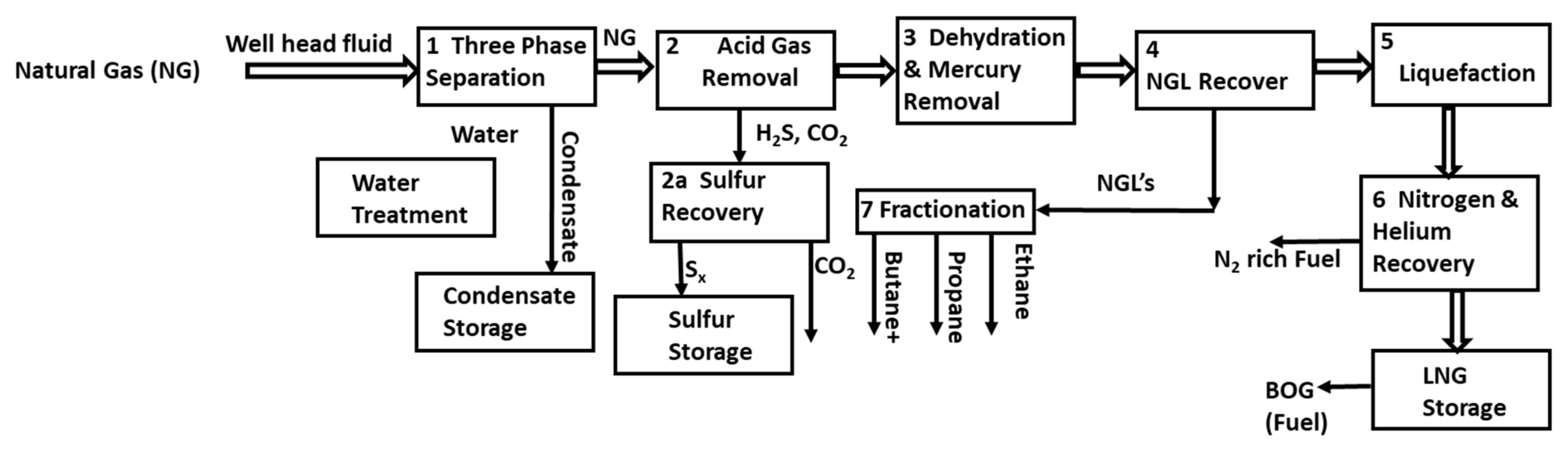
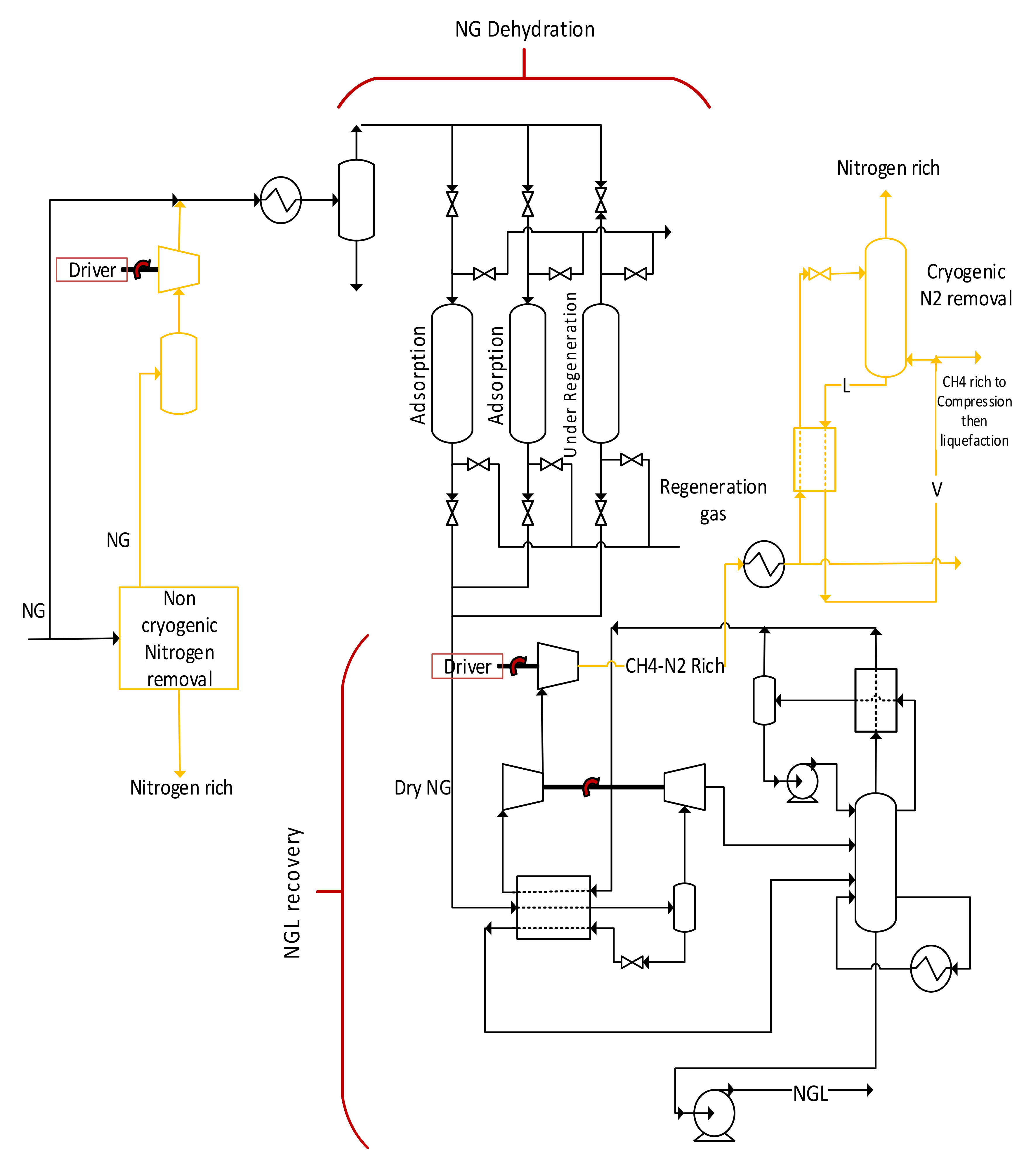
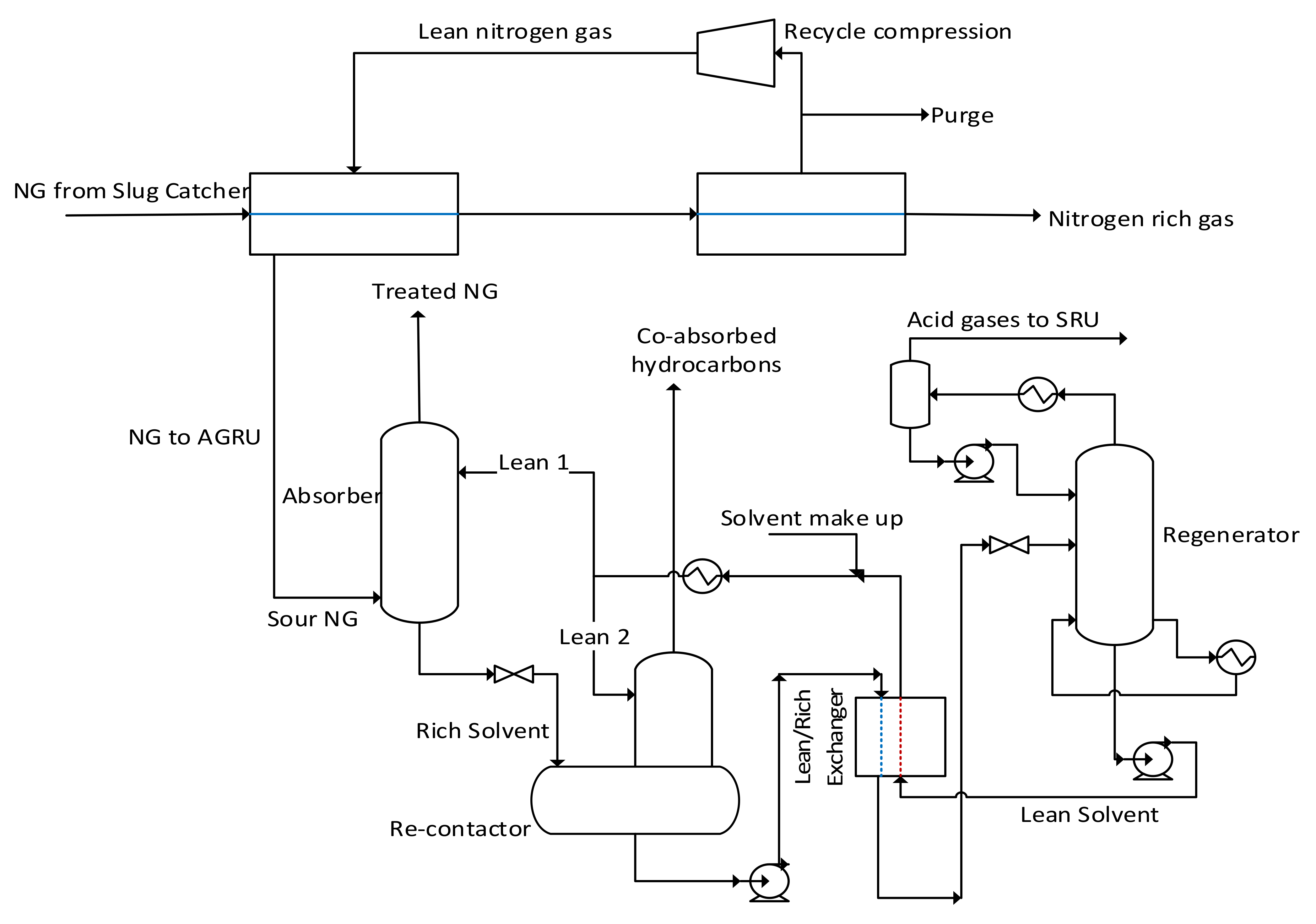
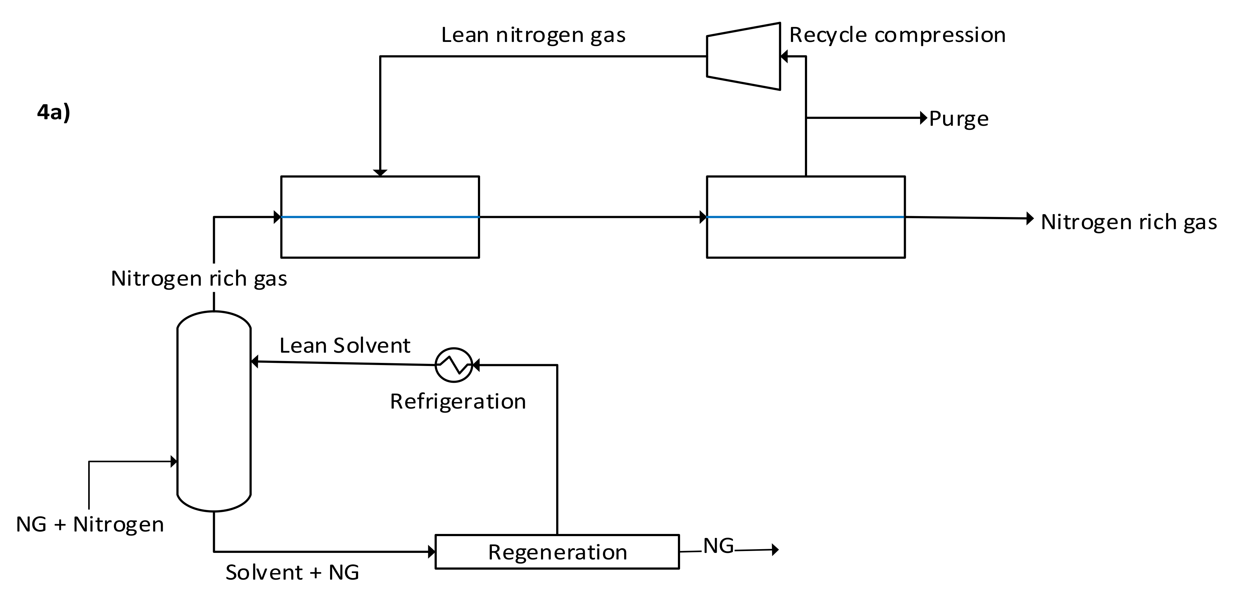
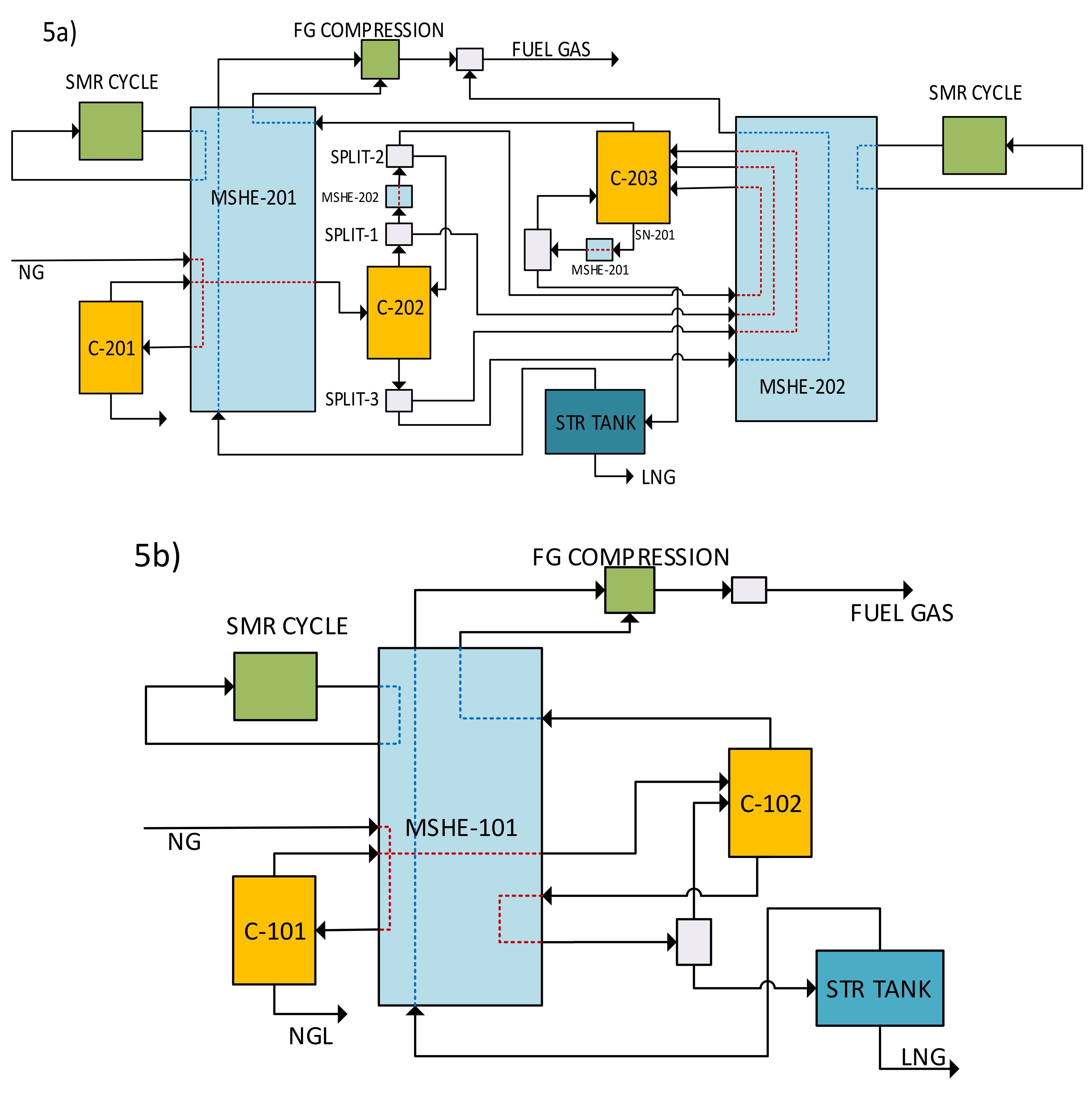
3. Upfront N2 Removal Methodology

The first stage of implementing upfront N2 removal methodologies includes shortlisting the available N2 removal technologies. The selected technologies can be thoroughly modeled and optimized in standalone modes. The models can be constructed to capture material/energy balances, rigorous vapor–liquid equilibrium, and essential hydraulics, including pressure drops. Commercially available simulation packages, such as Aspen PlusTM, PromaxTM, Aspen AdsorbersTM, and MATLABTM, can be used to model these technologies. This task should include a detailed parametric analysis to identify the operating windows of the shortlisted schemes. Key variables, such as separation rate, kinetics, and capacity, which impact the removal performance, should be investigated to identify the degree of improvement and enhancement in the removal efficiency. This could be followed by standalone mathematical optimization to maximize N2 removal while minimizing capital and energy costs.
Considering all of these variables plus the fact that a baseload LNG plant is very complex, thoroughly studying each option will require a significant amount of time, if not be completely impossible. What is proposed instead is to rapidly evaluate plant performance with different N2 removal technologies, locations, purities, and recoveries using exergy analysis. Here, the full LNG process along with the shortlisted removal configurations will be represented by reversible processing steps (i.e., zero driving forces such as temperature difference and concentration gradient). Using the efficiencies derived from standalone N2 removal technologies and the optimized LNG models [10,11], exergy losses can be calculated for each unit with different N2 removal variables (i.e., technology, purity, recovery) installed at different locations. A trade-off study between NG throughput gain and exergy losses shall be identified for the complete plant. Studying the key operating variables, such as temperatures, pressures and efficiencies of each proposed process, will allow rapid identification of their impact on the LNG process. These should give the different optimistic performances that may serve as targets (or benchmarks) for optimizing and retrofitting the LNG plant with the top identified candidates for the upfront N2 removal technology. With this approach, it is believed that the promising candidates for the subsequent detailed and full-scale plant optimization/retrofitting can be filtered out.

4. Literature Analysis of the Upfront N2 Removal Technologies

This section presents the most promising and technically available upfront N2 removal technologies. Based on our literature review the available upfront N2 removal technologies can be classified as (1) Physical Separation, (2) Chemical Separation and Gas Hydrate.

4.1. Physical Separation Technologies

The physical separation technologies have been studied extensively in the literature for multiple applications such as pipeline-quality natural gas, coal-bed methane (CBM), flue gas management, and LNG. In this section, the main goal is to explore and discuss the potential physical separation means for possible implementation as an upfront N2 removal process in the LNG supply chain. The main physical processes that were investigated broadly are adsorption, membranes, and cryogenic distillation, the current technology, implemented in LNG trains.

4.1.1. Adsorption

Adsorption has proven to be a huge success in gas separation processes. This technology has a high TRL that ranges from 9 for the pressure swinging/vacuum to 5–7 for temperature swinging adsorption. It has been established commercially for N2 removal from NG [12]. Adsorption is considered advantageous over cryogenic distillation in terms of process economics and could be a promising technology; however, the key operational parameter to this process is to find the ideal adsorbent in terms of selectivity and capacity. The literature review showed that most of the published works focus on identifying adsorbents for the separation of N2 from CH4 as a model of NG. The most promising adsorbents are summarized as follows:
  • Metal-organic frameworks (MOFs): Synthetic nano-porous materials made up of a network of metal ions and organic ligands characterized by high selectivity, adjustable pore size, and pore volumes [13,14]. The MOFs technology is assessed as being at TRL-5 to 6 presuming a favorable testing result.
  • Zeolites: Microporous aluminosilicates characterized by low cost, robustness, and high pore volume. Some examples of zeolites used in CH4/N2 separation are 5 A, BETA, and clinoptilolite (CLINO) [12,15]. Zeolite adsorption was set at TRL 5–7.
  • Porous-aromatic frameworks (PAFs): Open-structure aromatic frameworks that are superior over MOFs and zeolites in terms of ultrahigh surface area and high stability [16].
  • Activated carbon (AC): A well-established commercial adsorbent (RTL 7–9) that is cheap, thermally stable, can be easily modified, and has a well-developed structure [17,18].
  • Carbon molecular sieves (CMS): Solid adsorbents manufactured from organic sources such as coconut shell and coal, differing from AC in having a narrower range of pore size [19,20]. It has been stated that they possess a kinetic selectivity for N2 over methane [21]. The TRL of the CMS is ranged from 6–9.
  • Titanosilicates: Molecular sieves that have been established commercially for N2 adsorption from natural gas for Molecular GateTM [22]. They have proven advantageous in energy consumption, operational costs, flexibility, and product purity [23].
Table 1 presents a highlight of the most recent and most important adsorption studies conducted for possible N2 separation by adsorption. Both experimental and simulation methodologies were used to investigate the separation performance. As it can be noted, the separation of methane and nitrogen is achievable through adsorption, and multiple adsorbents have proven considerable selectivity indicating excellent separation. However, most well-established adsorbents such as MOFs or zeolites favor methane over N2, indicating that if these adsorbents were to be used in NG processing plants, a huge amount would be required since methane is the majority component. Furthermore, desorption steps would be required, ensuring that the quality of the gas obtained has not been affected. For the aforementioned reasons, it is more attractive and practical to have an adsorbent with high selectivity to N2, as it is a minority component and inert that would not be as useful compared to methane. It is worth highlighting that although the percentage recovery in all the studies presented in Table 1 is higher than 90%, the composition of N2 in the mixture (CH4/N2) was higher than 10%, which is considered very high compared with the composition of N2 in NG. Therefore, further investigation on comparable a composition is required to draw conclusions.
It can also be understood that numerous works have studied adsorption on an equimolar binary methane–nitrogen mixture, which does not simulate typical natural gas content. These kinds of studies are more useful when discussing the purification of coal-bed methane (CBM), low-grade natural gas, or flue gases. They would not reflect upon sales of natural gas or LNG [26,38,39,40]. This is considered a huge drawback in the literature as the N2 content in NG is usually below 10% and is required to be reduced up to 1–4%, as with the case in cryogenic distillation to meet the sales gas specifications [9,41]. Aside from that, some studies tested some adsorbents for a gas mixture having 10–20% mol N2, out of which there would be some potential for upfront N2 removal. Furthermore, most of the research done was carried out on the basis of low pressure (i.e., 1–3 bar). It would have been more useful to study at high pressures since NG is typically obtained at high pressure [42], and in that case, unnecessary additional costs would be needed to expand and re-compress that gas for N2 removal. Another drawback in the literature is that most of the research done on adsorption has focused on studying the selectivity of the adsorbent used without discussing the recovery/purity or heating value of the gas obtained, which is a necessity for the field of NG studies.
Emphasis should be placed on the studies that have a potential for upfront N2 removal, use mixtures that mimic real NG, and highlight the specifications for the product obtained. MOFs and PAFs were tested for gas mixtures having 10% N2 on both an experimental basis and a simulation basis. For similar feed specifications and operating conditions, Hu et al. [31] obtained a significant selectivity for N2 using PAFs (i.e., 118 for 10% N2 content in the feed) in their GCMC simulation study. Li et al. [29] obtained a CH4 selectivity of 16 using MOF in their experimental study. This could indicate the superiority of PAFs over MOFs and their potential over MOFs to be used for N2 removal since most MOFs are CH4-selective.
Other than MOFs and PAFs, CMS was tested by Effendy et al. [21], who optimized the pressure-swing adsorption (PSA) process using CMS to treat a binary CH4-N2 mixture having 10 mol% N2. Using their simulation model and varying the operating pressure between 3–16 bar, 97.9% pure methane was obtained, reducing the N2 content from 10% to about 2%, matching the pipeline’s gas specification (i.e., below 4% of N2) [43]. They have included a techno-economic analysis for this process, concluding that the net revenue expected is around USD 4.7–5.5 million/scfd for a feed throughput between 2 and 10 MMscfd where the cost was dominated by the initial and maintenance costs for the adsorption column (40%) in addition to methane loss (40%). This latter cost might make implementing this process questionable.
Another potential adsorbent for upfront N2 removal is titanosilicate. Weh et al. [32] have obtained 95.7% pure methane from a binary methane-N2 mixture (85 mol% CH4 and 15 mol% N2) with an overall recovery of 99% using a titanosilicate named ETS-4. This adsorbent was tested under high pressure of 20 bar, indicating its prospective use in the LNG train. In addition, titanosilicates have proven successful for CO2 removal as well as N2 in multiple works [22,23]. Therefore, they may eliminate the need for an amine absorption column for CO2 removal. Finally, titanosilicates are well-established commercially for Molecular GateTM adsorption having an overall CH4 recovery of 90–93% producing gas within the pipeline specification [22,43]. The associated cost of using titanosilicates in the industry was estimated to be around 0.4 to 1.2 USD/MCF feed for a feed flow of 0.5–10 MMSCFD.
After an extensive survey of the literature, it was found that most adsorbents, if not all, are CH4-selective at typical NG conditions. The CH4-selective adsorbents could be used effectively for CH4/N2 separation, but it would be more encouraging to find N2-selective adsorbents, as with the case of CMS and titanosilicates, which showed huge potential in the field.

4.1.2. Membranes

The use of membranes (TRL 9) in gas separation has been growing recently due to their flexible operation, small footprint, reduced investment cost, and energy consumption [44,45,46]. Membrane separation is a pressure-driven process where a gas permeates through a membrane from a high-pressure zone to a lower pressure zone.
The progress of membrane technology for gas separation advanced with the manufacturing of different types of membranes, including mixed matrix membranes (MMMs) [47]. This type of membrane, which is an alternative to polymer-based membranes, was developed to improve the separation performance. The MMMs are based on separation properties of the porous materials that are used as fillers with excellent economical value and stable mechanical properties. The MMMs can be tailor-made to have excellent permeability and selectivity to specific compounds (e.g., CO2 and O2). The MMMs have been successfully used for the separation of CO2 from CH4 [48] as well as CO2 from N2 [49,50]. A combination of MOFs and zeolites with MMMs was used for the separation of CO2/N2, CO2/CH4, O2/N2, and H2/CH4 mixtures [51]. For N2/CH4 separation, various types of membranes were used:
  • Polymeric membranes: The most commercial membranes, which can be rubbery like poly-siloxanes [52] or glassy like polyimides [53].
  • Zeolite membranes: Inorganic membranes where microporous zeolite crystals are grown as a layer supported by a flat or tubular surface, such as silicoaluminophosphate (SAPO) [54] and SSZ-13 [55] membranes.
  • Mixed-matrix membranes (MMMs): Membranes fabricated from organic polymers and inorganic materials to increase the permselectivity of the membrane where inorganic materials could be zeolites, MOFs, or CMS [44].
To appreciate this technology as an upfront N2 methodology, consider the process shown in Figure 3. Here, the membrane technology is installed to remove all N2 before the AGR step, assuming it is a viable option. The membrane will selectively permeate NG and reject N2 by applying a pressure difference across the membrane [4]. The permeated NG will thus be available at a lower pressure. This can have a severe impact on the acid gas removal rate in the absorber, which can result in producing off-spec sweet gas. More circulation at lower temperatures can remove more acid gases even at lower pressures; however, this may increase the regenerator reboiler load beyond its design limit.
The direction of membrane research for CH4/N2 separation in the literature is similar to that of adsorption: the majority is focused on the design of the membrane and testing its permeance and selectivity without considering real-life scenarios or discussing the product purity and recovery obtained, as can be seen in Table 2 [44,45,54,55,56,57,58]. All types of membranes formerly described have been tested for CH4/N2 separation. As with adsorption, some membranes favor the permeation of N2, and others favor the permeation of methane. In an early simulation study, Baker and Lokhandwala [53] reported that to reduce the N2 content in a gas stream from 10% to 4% using membrane separation, either a CH4-permeable membrane with a selectivity of 6 or an N2-permeable membrane with a selectivity of 17 is required. However, as the gas is coming at high pressure and it being necessary to conserve this pressure to eliminate the costs of downstream compressors, it is essential to have the membrane N2-permeable and keep methane on the retentate side to conserve its pressure. Some commercial membrane units in Kentucky and California use a CH4-permeable membrane and re-compress the gas after N2 removal either using the residual gas or through external power compression [52].
As shown in Table 2, both types of membranes are widely available and were tested in earlier research work with moderate permselectivities for both types. For N2-permeable membranes, it was determined that most of them are highly permeable to CO2 as well. It can separate CO2 and N2 from methane, making it advantageous as the CO2 removal step would be eliminated from NG processing. Nevertheless, a general trend was observed where higher pressures reduced the permselectivity of the membranes; thus there were fewer separation efficiencies [45,55,56,57]. This indicates that there might be a need to reduce the pressure of the gas and re-compress it again, as is the case in CH4-permeable membranes. Yet, PBI mixed-matrix membrane and SSZ-13 zeolite membrane have shown considerable performance over other membranes as they have an order of magnitude higher permselectivities compared to other membranes [55,57,58].
The CH4-permeable membranes were tested and developed commercially in multiple fields. Lokhandwala et al. [52] tested a membrane using the ChemCad 5.5 commercial simulation package, assuming a 10 MMscfd feed gas coming at a pressure of 32 bar where the N2 content was reduced from 10% to less than 4%. In their study, they estimated the installation cost of these membranes to be USD 4–8 million, with annual revenue of USD 3.5–7 million [52]. In addition, they reported two field membrane units working successfully: one reducing the N2 content from 7% to 3.8% with an overall hydrocarbon (HC) recovery of 80%, and the other reducing the N2 content from 16% to 9%, increasing the heating value of the gas from 900 BTU/scf to 990 BTU/scf. Although the latter provides an overall 95% hydrocarbon recovery, the former provides better N2 removal despite its lower recovery. Nonetheless, both units would require an additional upgrade for better gas conservation and more N2 removal.
The literature review on the use of membrane technology for upfront N2 removal suggests that an effective process requires multi-stage membranes to reduce the N2 content and satisfy LNG specifications. The efficacy of such technology must be proven to explain the significant costs required for gas re-compression in the case of CH4-permeable membranes, as there might be a trade-off between product quality and product pressure [46].

4.1.3. Hybrid Upfront N2 Removal Technologies

Instead of using adsorption or membrane N2 removal processes, which are expensive to operate and implement and may result in poor performance, synthesizing a new hybrid system of these current technologies could have significant potential. A scheme of the proposed hybrid systems is shown in Figure 4a. The system uses both absorption and membranes to purify NG from nitrogen. The membrane step may also be replaced by adsorption or another viable option. NG is first fed to a high-pressure absorption column to remove as much NG as possible, using a suitable solvent such as low-temperature oil (i.e., heavy hydrocarbons) [4]. The N2 rich gas leaving the absorber column is further purified in a membrane system to recover as much of the unabsorbed NG as possible. On the other hand, the solvent plus NG leaving the absorber bottom will need to be regenerated for solvent reuse and NG recovery. One of the motivations of this scheme can be to remove as much N2 as possible while minimizing the loss of the NG pressure (as in the case of processing all the NG into a membrane or adsorber system). Consequently, it may be beneficial to minimize NG carryover from the top of the absorber such that it minimizes the load on the membrane, which can result in excessive pressure drop hence, reducing NG re-compression. This would also mean a need for high-pressure solvent regeneration. If the solvent is made of heavy hydrocarbons (e.g., NGLs) then the solvent regeneration may be carried out in the existing NGL recovery step of the plant, see Figure 4b. While this may increase the NGL column reboiler rate, the K-1 compressor will process a stream without (or with lower) nitrogen, reducing its power. Pinch analysis may also be needed to exploit any available wasted refrigeration in the plant for lean solvent chilling before the absorber. The plant-wide degrees of freedom will also need to be optimized to determine the overall benefits without violating the process constraints, in this case, the NGL recovery heat exchangers, compressors surge/stonewall, columns hydraulics, etc. This newly developed N2 removal scheme needs additional plant retrofitting. For example, the C-1 column in the NGL recovery step may require replacing the existing internals with high-capacity trays or packing, as it will be processing NG plus the oil solvent.

4.1.4. Distillation

Figure 5a illustrates the potential of using the distillation process (TRL 9) as an upfront N2 removal technology. This can be achieved by integrating the N2 removal process with an NGL recovery column (C-201), one high-pressure nitrogen removal column (C-202), and one low-pressure nitrogen removal column (C-203). The cold section of the NG upgrading process comprises a natural gas liquid (NGL) recovery unit, liquefaction, and N2 removal unit (NRU). The energy required to achieve the cold temperature is provided by an external refrigeration cycle in a multi-stream heat exchanger (MSHE). Figure 5b describes the cold section of a conventional large-scale LNG plant. The sweet natural gas (NG) from AGRU is liquefied in the cold section after the separation of the heavy hydrocarbons in the NGL recovery column (C-101). The lean NG from the NGL recovery unit undergoes further sub-cooling and is sent to single-column NRU(C-102). The LNG is then flashed to near atmospheric pressure to be stored in atmospheric storage tanks. The waste hydrocarbon-rich stream is used as fuel gas to generate power in a gas turbine to meet the plant’s power requirements. Specialized heat transfer equipment such as MSHE allows multiple streams to exchange heat simultaneously and achieve the operating conditions. The MSHE has a quite complex and compact design with complex flow channels for reliable heat transfer over a wide pressure range [59]. The capacity of the MSHE is the bottleneck of the process, and removal of inert gases from the feed stream before it enters the MSHE will create volume for processing more hydrocarbon and increase the capacity of the plant. The introduction of an N2 removal unit upfront of existing MSHE in the LNG plant, with the cold section operating at maximum capacity, generates room for more hydrocarbon to be liquefied and reduces the cold energy requirement from the MR cycle.
Different research works have extensively studied energy optimization in the LNG plant’s cold section and proposed various configurations for N2 removal by integrating the NRU with liquefaction and NGL recovery [60,61,62,63]. However, no research discusses the implications and methods for removing N2 upfront of the liquefaction process. Figure 5a presents the proposed integrated distillation column design for the cold section in upfront N2 removal. The process streams generated due to the addition of a column in the NRU directed to MSHE-202 and an external MR cycle provide the requisite cooling energy. The stream (SN-153) subcooled in MSHE-201 has depleted N2 content similar to that of the LNG product stream. The volume occupied by N2 in-stream SN-153 is replaced by hydrocarbons by increasing the feed flow rate. The upfront N2 removal before MSHE-201 would lead to an increase in plant capacity. The plant’s power requirements can be satisfied by a gas turbine utilizing the fuel gas stream and energy balance between required and generated fuel gas to ensure optimal operation of the plant.
The model of the proposed upfront N2 removal via double-column distillation was developed using Aspen HYSYS V.10 and PSO algorithm coded in MATLAB. For a process with a feed flow rate of 530 MMSCFD, a minimum of 17.6% upfront N2 removal before the MSHE-201 process resulted in more than 5% of the specific power requirement (from 33.13 MW/MTA to 31.4 MW/MTA) and a 16% increase in the plant capacity (from 530 to 619 MMSCFD).

4.2. Chemical Separation Technologies

In chemical separation, the reagent to be used must be reactive with one component and non-reactive with the other component for an ideal separation. In the case of N2 removal, an N2-reactive reagent that is simultaneously non-reactive with CH4 is needed to preserve the BTU content of the gas. Table 3 lists all studies covering the chemical separation of N2 from NG. Throughout the literature, surveying for potential chemical separation processes, two main processes were found: absorption through complexation and adsorption using lithium (Li) metal.
As stated earlier, all chemical separation processes target the N2 instead of methane in the gas. It would not be reasonable to consume the gas needed and have an alternative to producing it back. The absorption process mainly employs a solvent that dissolves N2, not methane. Solvents that have proven successful are transition metal complex (TMC) solutions. In an experimental study, Friesen et al. [64] had a patent for using the combination of ligands and TMC solution to treat a gas feed with 15% N2 content coming at typical NG conditions. The utilized solutions managed to have around 5.75 N2 selectivity over methane. Li et al. [65] achieved a N2 selectivity over methane of around 2 using ruthenium-based TMC at ambient temperature and a pressure of 30 bar. However, Li stated that a ruthenium-based TMC absorption process would be hindered in industrial-scale applications due to its limited availability and its low concentration in an aqueous solution [66]. Furthermore, Gilbertson et al. [67] established using iron-phosphine complexes for the separation of N2 from NG at low temperatures and pressures, but they did not state the change in the N2 content using these absorbents. Although all the aforementioned studies did not report any information about the purity of the gas obtained, other studies obtained NG at pipeline specifications as well as LNG specifications.
Using a molybdenum-based organometallic complex solution, Bomberger et al. [68] treated NG coming at typical well-head conditions reducing the N2 content from 20% to less than 4%, where the complex bound more readily at a higher pressure and was not affected by the presence of methane. The operating cost associated with this absorption process was estimated to be around USD 1–3 million/SCF for small-scale process (i.e., 1–2 MMSCFD) and USD 0.3 million/SCF for large-scale process (i.e., 75 MMSCFD) [68].
Aside from the former absorption process, lithium-based adsorption was found to be promising, reducing the N2 content in the gas to low levels, less than 2% [66,69]. This process consists of different steps (Figure 6), including the electrolysis of lithium chloride to obtain lithium. In a commercially established process, the lithium reacts with N2 in natural gas, producing Li3N (Reaction 1). A reaction of lithium nitride hydrolysis can be applied as a part of the proposed cycle (Reaction 2) and an additional step of treating lithium hydroxide with hydrochloric acid to obtain lithium (Reaction 3).
Reaction   1 :   6 Li + N 2 2 Li 3 N
Reaction   2 :   2 Li 3 N + 6 H 2 O 6 LiOH + 2 NH 3
Reaction   3 :   4 LiOH 2 H 2 O + O 2 + 4 Li
In a numerical simulation analysis, Gu et al. [69] concluded that the N2 content of the gas could be reduced at ambient temperature and 1–80 bar pressure from 10% or 4% to 0.5% N2, achieving LNG specifications where moisture-pretreated lithium is used as an adsorbent, not dry. The advantage of using moisture-pretreated lithium instead of dry lithium was emphasized by Li [66] as water produces active edge sites on lithium and initiates the reactions with nitrogen. In an experimental study, Li [61] used the moisture-pretreated lithium to reduce the N2 content for a 20-SCCM-NG from 10% down to 2% at a pressure of 8.8 bar. An economic analysis for this adsorption process was conducted where the N2 removal process was estimated to be profitable with a revenue of USD 88 per ton N2 removed from a 5 MMTA LNG plant. This process reduced the N2 content from 10% to 1%. The process is considered profitable as lithium can be easily regenerated, producing ammonia (reaction 2) that can be sold as a byproduct covering the cost of the N2 removal process [61].

4.3. Gas Hydrate Technology

Different research works have investigated gas hydrate production (TRL 4) in aqueous solutions and have proposed possible ways of gas-separation methods using the variations between equilibrium mole fractions in vapor and hydrate phase [70]. Gas hydrates are non-stoichiometric compounds that are combined between the water and the light gas molecules by Van der Waals forces. The host lattice gas molecules that are composed of hydrogen-bonded water molecules stabilize the well-defined cages with variable equilibrium pressures. Different studies showed that the hydrate-formation pressures of N2 and hydrocarbon (e.g., CH4) are 14.3 and ~2.56 MPa, respectively [71]. Therefore, the hydrocarbon can go through a phase change from gas to solid at low to moderate pressures, while N2 does not. Consequently, the hydrocarbon can be enriched while N2 is rejected [72].
The hydrate-based technology has been extensively studied for seawater desalination, marine carbon dioxide sequestration, gas separation processes, natural gas storage and transportation, and cold energy storage applications in the past decades [73]. Recently, numerous patented unit operations were proposed on the use of the gas hydrate for the separation of CO2 or N2 from the gas stream. However, none of these technologies are in operation at a commercial scale and, in most cases, still in the developing or pilot testing phase. The gas separation processes using hydrate formation can be implemented by exploiting the difference in the formation conditions (pressure and temperature) for different gas hydrates. Although the hydrate separation method is carried out in the presence of water, hydrate promoters, such as tetra-n-butylammonium bromide (TBAB), tetrahydrofuran (THF), sodium dodecyl sulfate (SDS), are generally added to reduce the energy consumption, decrease the equilibrium pressures of hydrate formation, and increase the hydrate formation rate.
Most of the proposed hydrate-based technologies are based on a stirred tank reactor that involves the use of promoter molecules to decrease the required operating pressure or the use of a bubble-column to promote high contact time between the gas and liquid, which was often highlighted as a limiting factor in the formation of gas hydrates. The separation of CO2 and/or N2 from a gas mixture using hydrate required a multi-step process to accomplish an adequate separation due to the difficulties in enclatherate the gas stream into the hydrate phase. The process includes passing the NG through hydrate forming reactor where the N2-rich stream is released from the reactor, while the NG passes through the hydrate milter and settler to be separated as an NG free of nitrogen [74]. The regenerated hydrate can be recycled back to the reactor for further use. It was reported that the off-gas from the hydrate forming reactor is lean in hydrocarbons due to the preferential occupancy of hydrocarbon over N2 in the hydrate cages [9].
As the hydrate formation is exothermic, the removal of heat and control of operating temperature is crucial. Therefore, a fluidized-bed heat exchanger was used in all the applications that involve hydrate formation [75]. A continuous-flow gas-hydrate reactor was recently developed by Marathon Oil Company, tested on a pilot scale, and showed the capacity of generating a 410 wt% hydrate slurry at a production rate of 4750 kg/day. The process includes beads of solid media fluidized in the heat exchanger tubes and gently flow upward to reduce the chance for solid deposition and enhance the heat transfer coefficients [75].
Dong et al. [72] investigated the purification of the CH4 stream from N2 using a mesoporous carbon material (CMK-3) in the presence of tetrahydrofuran that lowers the hydrate formation pressure. The test successfully improved the composition of CH4 in the gas stream from 50 mol% to 70 mol% under optimal operating conditions of 1.0–1.4 MPa and 275.15 K. The study concluded that this hydrate can be easily regenerated and reused for the separation of N2 from hydrocarbons. Cai et al. [76] showed that the gas hydrate formed by using sodium dodecyl sulfate (SDS) and tetrahydrofuran (THF) as chemical promoters is effective in recovering CH4 from CH4/N2 gas generated from coal-bed methane (CBM). The test, which was carried out at 1.50–4.50 MPa and 279.15 K, increased the methane composition from 50 mol% in the feed to 70% in the hydrate slurry. Although these promoters (THF and SDS) were effective and increased the hydrate formation and separation efficiencies, the irritation, volatility, and corrosivity are challenges to be resolved before large-scale application. Sun et al. [77] used bio-additives such as tea polyphenol and catechin to enhance and promote hydrate formation. The bio-clathrates formed at 5.5–9 MPa and 274.15 K were used to recover CH4 from CBM containing 34 mol% CH4 and the balance N2. The bio-additives had a significant effect on the hydrate formation rate and storage capacities and consequently the separation efficiency. The gas hydrate developed by adding 1.0 wt% of catechin was selective to CH4 with a separation factor of 5.31. This hydrate increased the composition of CH4 from 34% to 61%. Another hydrate prepared using 1.0 wt% of tea polyphenol as a promoter resulted in CH4 recovery and separation factor of 57.9% and 4.28, respectively.
Zhang et al. [78] examined the role of amino acids (L-tryptophan and L-leucine) in the presence of THF on hydrate formation and the efficiency for CH4 gas recovery from CBM with a composition of 30 mol% CH4 and 70 mol% N2. The results showed that the addition of 5000 ppm of L-tryptophan at 3.0 MPa and 283.2 K increased the hydrate growth rate by 130% and enhanced the CH4 recovery from 58.3% to 71.4%. Although the addition of L-leucine did not impact the kinetics, it resulted in the highest CH4 enrichment in the hydrate phase.
Sun et al. [79] explored the possibility of deploying alkyl polyglucosides (n-hexyl polyglucosides, C6 APG, and octyl-decyl polyglucosides, C8–C10 APG) as promoters for CH4 hydrate formation and the separation from a stream containing 34.65 mol% CH4 and the balance N2. The polyglucosides showed no effect on the process thermodynamics but act as a kinetic promotor and increased the hydrate formation rate and storage capacity. The C8–C10 APG exhibited a separation factor and percentage CH4 recovery of 4.14% and 51.33%, respectively.
The aforementioned literature suggests a promising potential of gas hydrate for the separation of CH4 from and N2. All the studies showed that CH4 has a higher hydrate formation rate than N2. However, applying this technology as upfront N2 removal in the LNG process required further investigation due to the following reasons: (1) The studied N2 composition in different studies was high (≥30%) compared to the content in NG, (2) Most of the studies focused on a gas stream consisting of CH4/ N2, which is different from the composition of the LNG, (3) to be economically feasible, any proposed upfront N2 technology must have acceptable efficiency to remove very low concentrations of N2 from LNG stream, and (4) It is not clear if using hydrate formation as upfront N2 removal technology will be feasible for low-quality feed consisting of N2 content. Therefore, further investigation is required to investigate the feasibility of a hydrate formation-based separation process as upfront nitrogen removal in a baseload LNG plant with low nitrogen content in feed (5–10 mol%).

5. Conclusions

The characteristics, design considerations, and efficiencies of the currently available upfront N2 removal technologies from NG were covered in this review. Replacing the current industry dominance of the NRU at the tail of the process could substantially enhance the economics of large-scale LNG processes. The objective is to identify the best nitrogen removal process and its proper integration upfront of the liquefaction step. Cryogenic distillation is likely to remain the main N2 removal technology in the near future due to high separation efficiency. The use of N2 selective membrane technologies in removing N2 from NG has significantly increased, though the need for multi-stage membranes is still considered a technical obstacle. There remains significant scope for the development of better performing N2 selective membranes. Technologies based on N2-selective absorption and adsorption are promising commercial technologies for small-scale processes that require further inspections. Gas hydrate still required further investigation to accommodate the low concentration of N2 in NG. There is future potential for efficient upfront N2 removals, such as hybrid adsorption/membrane and chemical technologies. Synthesis of stable and selective N2 solvents and/or adsorbents would improve the emergence of these processes as upfront N2 technologies. Challenges such as suitable location, retrofitting the proposed technologies, degree of removal, and cost require further investigation.

Author Contributions

Literature and Data curation, A.O.; Formal analysis, F.A.; Investigation, E.I.A.-M., Methodology, A.P., A.O., F.A.; Project administration, F.A., I.A.K. All authors have read and agreed to the published version of the manuscript.

Funding

National priority research fund No. NPRP11S-1231-170152, Qatar National Research Fund, a member of the Qatar Foundation.

Acknowledgments

The authors acknowledge the financial support through from Qatar National Research Fund grant No. NPRP11S-1231-170152. The statements made herein are solely the responsibility of the authors.

Conflicts of Interest

The authors declare no conflict of interest.

Abbreviations

ACActivated carbon
CBMCoal-bed methane
CMSCarbon molecular sieves
HCsHydrocarbons
LNGLiquefied natural gas
NGNatural gas
PSAPressure swing adsorption
C3/MRPropane/mixed refrigerant
BOGBoil-off gas
AGRAcid gas removal
MOFsMetal-organic frameworks
CBMCoal-bed methane
SAPOSilicoaluminophosphate
NRU Nitrogen removal unit

References

  1. Osorio-Tejada, J.L.; Llera-Sastresa, E.; Scarpellini, S. Liquefied natural gas: Could it be a reliable option for road freight transport in the EU? Renew. Sustain. Energy Rev. 2017, 71, 785–795. [Google Scholar] [CrossRef] [Green Version]
  2. Tagliabue, M.; Farrusseng, D.; Valencia, S.; Aguado, S.; Ravon, U.; Rizzo, C.; Corma, A.; Mirodatos, C. Natural gas treating by selective adsorption: Material science and chemical engineering interplay. Chem. Eng. J. 2009, 155, 553–566. [Google Scholar] [CrossRef]
  3. Kurle, Y.M.; Wang, S.; Xu, Q. Dynamic simulation of LNG loading, BOG generation, and BOG recovery at LNG exporting terminals. Comput. Chem. Eng. 2017, 97, 47–58. [Google Scholar] [CrossRef]
  4. Kuo, J.; Wang, K.; Chen, C. Pros and cons of different Nitrogen Removal Unit (NRU) technology. J. Nat. Gas Sci. Eng. 2012, 7, 52–59. [Google Scholar] [CrossRef]
  5. Gabrielli, P.; Gazzani, M.; Mazzotti, M. On the optimal design of membrane-based gas separation processes. J. Membr. Sci. 2017, 526, 118–130. [Google Scholar] [CrossRef]
  6. Ohs, B.; Lohaus, J.; Wessling, M. Optimization of membrane based nitrogen removal from natural gas. J. Membr. Sci. 2016, 498, 291–301. [Google Scholar] [CrossRef]
  7. Saleman, T.L.; Li, G.K.; Rufford, T.E.; Stanwix, P.L.; Chan, K.I.; Huang, S.H.; May, E.F. Capture of low grade methane from nitrogen gas using dual-reflux pressure swing adsorption. Chem. Eng. J. 2015, 281, 739–748. [Google Scholar] [CrossRef] [Green Version]
  8. Anna, H.R.S.; Barreto, A.G., Jr.; Tavares, F.W.; do Nascimento, J.F. Methane/nitrogen separation through pressure swing adsorption process from nitrogen-rich streams. Chem. Eng. Process. Process Intensif. 2016, 103, 70–79. [Google Scholar] [CrossRef]
  9. Rufford, T.E.; Smart, S.; Watson, G.C.Y.; Graham, B.F.; Boxall, J.; Diniz da Costa, J.C.; May, E.F. The removal of CO2 and N2 from natural gas: A review of conventional and emerging process technologies. J. Pet. Sci. Eng. 2012, 94–95, 123–154. [Google Scholar] [CrossRef]
  10. Kotas, T.J. The Exergy Method of Thermal Plant Analysis; Elsevier: Amsterdam, The Netherlands, 2013. [Google Scholar]
  11. Bouabidi, Z.; Katebah, M.A.; Hussein, M.M.; Shazed, A.R.; Al-musleh, E.I. Towards improved and multi-scale liquefied natural gas supply chains: Thermodynamic analysis. Comput. Chem. Eng. 2021, 107359. [Google Scholar] [CrossRef]
  12. Nandanwar, S.U.; Corbin, D.R.; Shiflett, M.B. A Review of Porous Adsorbents for the Separation of Nitrogen from Natural Gas. Ind. Eng. Chem. Res. 2020, 59, 13355–13369. [Google Scholar] [CrossRef]
  13. Wu, Y.; Yuan, D.; He, D.; Xing, J.; Zeng, S.; Xu, S.; Xu, Y.; Liu, Z. Decorated Traditional Zeolites with Subunits of Metal–Organic Frameworks for CH4/N2 Separation. Angew. Chem. Int. Ed. 2019, 58, 10241–10244. [Google Scholar] [CrossRef] [PubMed]
  14. Kim, T.-H.; Kim, S.-Y.; Yoon, T.-U.; Kim, M.-B.; Park, W.; Han, H.H.; Kong, C.-I.; Park, C.-Y.; Kim, J.-H.; Bae, Y.-S. Improved methane/nitrogen separation properties of zirconium-based metal–organic framework by incorporating highly polarizable bromine atoms. Chem. Eng. J. 2020, 399, 125717. [Google Scholar] [CrossRef]
  15. Silva, J.A.C.; Ferreira, A.; Mendes, P.A.P.; Cunha, A.F.; Gleichmann, K.; Rodrigues, A.E. Adsorption Equilibrium and Dynamics of Fixed Bed Adsorption of CH4/N2 in Binderless Beads of 5A Zeolite. Ind. Eng. Chem. Res. 2015, 54, 6390–6399. [Google Scholar] [CrossRef]
  16. Ben, T.; Qiu, S. Porous aromatic frameworks: Synthesis, structure and functions. CrystEngComm 2013, 15, 17–26. [Google Scholar] [CrossRef]
  17. Su, W.; Yao, L.; Ran, M.; Sun, Y.; Liu, J.; Wang, X. Adsorption Properties of N2, CH4, and CO2 on Sulfur-Doped Microporous Carbons. J. Chem. Eng. Data 2018, 63, 2914–2920. [Google Scholar] [CrossRef]
  18. Liu, F.; Zhang, Y.; Zhang, P.; Xu, M.; Tan, T.; Wang, J.; Deng, Q.; Zhang, L.; Wan, Y.; Deng, S. Facile preparation of N and O-rich porous carbon from palm sheath for highly selective separation of CO2/CH4/N2 gas-mixture. Chem. Eng. J. 2020, 399, 125812. [Google Scholar] [CrossRef]
  19. Ghazi-MirSaeed, M.; Matavos-Aramyan, S. Gaseous Mixtures Separation via Chemically-Activated Nano Silica-Modified Carbon Molecular Sieves. Silicon 2020. [Google Scholar] [CrossRef]
  20. Lemcoff, N.O. Nitrogen separation from air by pressure swing adsorption. In Studies in Surface Science and Catalysis; Dąbrowski, A., Ed.; Elsevier: Amsterdam, The Netherlands, 1999; Volume 120, pp. 347–370. [Google Scholar]
  21. Effendy, S.; Xu, C.; Farooq, S. Optimization of a Pressure Swing Adsorption Process for Nitrogen Rejection from Natural Gas. Ind. Eng. Chem. Res. 2017, 56, 5417–5431. [Google Scholar] [CrossRef]
  22. Mitariten, M.; Dolan, W. Nitrogen Removal from Natural Gas with the Molecular Gate Technology. In Proceedings of the Laurance Reid Gas Conditioning Conference, Norman, OK, USA, 2001. [Google Scholar]
  23. Neishabori Salehi, R.; Rahimpour, F.; Sharifnia, S. Adsorption of carbon dioxide, nitrogen and methane on modified titanosilicate type molecular sieves. J. Nat. Gas Sci. Eng. 2017, 46, 730–737. [Google Scholar] [CrossRef]
  24. Wu, Y.-J.; Yang, Y.; Kong, X.-M.; Li, P.; Yu, J.-G.; Ribeiro, A.M.; Rodrigues, A.E. Adsorption of Pure and Binary CO2, CH4, and N2 Gas Components on Activated Carbon Beads. J. Chem. Eng. Data 2015, 60, 2684–2693. [Google Scholar] [CrossRef]
  25. Chen, G.; An, Y.; Shen, Y.; Wang, Y.; Tang, Z.; Lu, B.; Zhang, D. Effect of pore size on CH4/N2 separation using activated carbon. Chin. J. Chem. Eng. 2020, 28, 1062–1068. [Google Scholar] [CrossRef]
  26. Peng, X.; Jin, Q. Ideal adsorbed solution theory, two-dimensional equation of state, and molecular simulation for separation of H2/N2/O2/CH4/CO in graphite nanofiber and C60 intercalated graphite. Sep. Purif. Technol. 2020, 237, 116369. [Google Scholar] [CrossRef]
  27. Jia, X.; Yuan, N.; Wang, L.; Yang, J.; Li, J. (CH3)2NH-Assisted Synthesis of High-Purity Ni-HKUST-1 for the Adsorption of CO2, CH4, and N2. Eur. J. Inorg. Chem. 2018, 2018, 1047–1052. [Google Scholar] [CrossRef]
  28. Chang, M.; Ren, J.; Yang, Q.; Liu, D. A robust calcium-based microporous metal-organic framework for efficient CH4/N2 separation. Chem. Eng. J. 2021, 408, 127294. [Google Scholar] [CrossRef]
  29. Li, L.; Yang, L.; Wang, J.; Zhang, Z.; Yang, Q.; Yang, Y.; Ren, Q.; Bao, Z. Highly efficient separation of methane from nitrogen on a squarate-based metal-organic framework. AIChE J. 2018, 64, 3681–3689. [Google Scholar] [CrossRef]
  30. Pillai, R.S.; Yoon, J.W.; Lee, S.-J.; Hwang, Y.K.; Bae, Y.-S.; Chang, J.-S.; Maurin, G. N2 Capture Performances of the Hybrid Porous MIL-101(Cr): From Prediction toward Experimental Testing. J. Phys. Chem. C 2017, 121, 22130–22138. [Google Scholar] [CrossRef]
  31. Hu, J.; Wu, F.; Gu, C.; Liu, J. Computational Design of Porous Framework Materials with Transition-Metal Alkoxide Ligands for Highly Selective Separation of N2 over CH4. Ind. Eng. Chem. Res. 2021, 60, 378–386. [Google Scholar] [CrossRef]
  32. Weh, R.; Xiao, G.; Islam, M.A.; May, E.F. Nitrogen Rejection by Dual Reflux Pressure Swing Adsorption Using Engelhard Titanosilicate Type 4. Ind. Eng. Chem. Res. 2020, 59, 22573–22581. [Google Scholar] [CrossRef]
  33. Henrique, A.; Karimi, M.; Silva, J.A.C.; Rodrigues, A.E. Analyses of Adsorption Behavior of CO2, CH4, and N2 on Different Types of BETA Zeolites. Chem. Eng. Technol. 2019, 42, 327–342. [Google Scholar] [CrossRef] [Green Version]
  34. Kennedy, D.A.; Tezel, F.H. Cation exchange modification of clinoptilolite—Screening analysis for potential equilibrium and kinetic adsorption separations involving methane, nitrogen, and carbon dioxide. Microporous Mesoporous Mater. 2018, 262, 235–250. [Google Scholar] [CrossRef]
  35. Kennedy, D.A.; Mujčin, M.; Abou-Zeid, C.; Tezel, F.H. Cation exchange modification of clinoptilolite–thermodynamic effects on adsorption separations of carbon dioxide, methane, and nitrogen. Microporous Mesoporous Mater. 2019, 274, 327–341. [Google Scholar] [CrossRef]
  36. Ouyang, T.; Zhai, C.; Sun, J.; Panezai, H.; Bai, S. Nanosol precursor as structural promoter for clinoptilolite via hydrothermal synthesis and resulting effects on selective adsorption of CH4 and N2. Microporous Mesoporous Mater. 2020, 294, 109913. [Google Scholar] [CrossRef]
  37. Fischer, M. Porous aluminophosphates as adsorbents for the separation of CO2/CH4 and CH4/N2 mixtures—A Monte Carlo simulation study. Sustain. Energy Fuels 2018, 2, 1749–1763. [Google Scholar] [CrossRef]
  38. Sun, T.; Hu, J.; Ren, X.; Wang, S. Experimental Evaluation of the Adsorption, Diffusion, and Separation of CH4/N2 and CH4/CO2 Mixtures on Al-BDC MOF. Sep. Sci. Technol. 2015, 50, 874–885. [Google Scholar] [CrossRef]
  39. Yang, Z.; Ning, H.; Liu, J.; Meng, Z.; Li, Y.; Ju, X.; Chen, Z. Surface modification on semi-coke-based activated carbon for enhanced separation of CH4/N2. Chem. Eng. Res. Des. 2020, 161, 312–321. [Google Scholar] [CrossRef]
  40. Han, Z.-Y.; Xing, R.; Zhang, D.-H.; Shen, Y.-H.; Fu, Q.; Ding, Z.-Y.; Tian, C.-X. Vacuum pressure swing adsorption system for N2/CH4 separation under uncertainty. Chem. Eng. Res. Des. 2019, 142, 245–256. [Google Scholar] [CrossRef]
  41. Faramawy, S.; Zaki, T.; Sakr, A.A.E. Natural gas origin, composition, and processing: A review. J. Nat. Gas Sci. Eng. 2016, 34, 34–54. [Google Scholar] [CrossRef]
  42. Katebah, M.A.; Hussein, M.M.; Shazed, A.; Bouabidi, Z.; Al-musleh, E.I. Rigorous simulation, energy and environmental analysis of an actual baseload LNG supply chain. Comput. Chem. Eng. 2020, 141, 106993. [Google Scholar] [CrossRef]
  43. Race, J.M.; Wetenhall, B.; Seevam, P.N.; Downie, M.J. Towards a CO 2 pipeline specification: Defining tolerance limits for impurities. J. Pipeline Eng. 2012, 11. [Google Scholar]
  44. Wang, S.; Guo, Q.; Liang, S.; Li, P.; Li, X.; Luo, J. [Ni3(HCOO)6]/Poly(styrene-b-butadiene-b-styrene) Mixed-Matrix Membranes for CH4/N2 Gas Separation. Chem. Eng. Technol. 2018, 41, 353–366. [Google Scholar] [CrossRef]
  45. Tanis, I.; Brown, D.; Neyertz, S.; Heck, R.; Mercier, R.; Vaidya, M.; Ballaguet, J.-P. A comparison of pure and mixed-gas permeation of nitrogen and methane in 6FDA-based polyimides as studied by molecular dynamics simulations. Comput. Mater. Sci. 2018, 141, 243–253. [Google Scholar] [CrossRef]
  46. Bernardo, P.; Drioli, E.; Golemme, G. Membrane Gas Separation: A Review/State of the Art. Ind. Eng. Chem. Res. 2009, 48, 4638–4663. [Google Scholar] [CrossRef]
  47. Miricioiu, M.G.; Iacob, C.; Nechifor, G.; Niculescu, V.-C. High selective mixed membranes based on mesoporous MCM-41 and MCM-41-NH2 particles in a polysulfone matrix. Front. Chem. 2019, 7, 332. [Google Scholar] [CrossRef] [Green Version]
  48. Miricioiu, M.G.; Niculescu, V.-C.; Filote, C.; Raboaca, M.S.; Nechifor, G. Coal Fly Ash Derived Silica Nanomaterial for MMMs—Application in CO2/CH4 Separation. Membranes 2021, 11, 78. [Google Scholar] [CrossRef] [PubMed]
  49. Dong, G.; Hou, J.; Wang, J.; Zhang, Y.; Chen, V.; Liu, J. Enhanced CO2/N2 separation by porous reduced graphene oxide/Pebax mixed matrix membranes. J. Membr. Sci. 2016, 520, 860–868. [Google Scholar] [CrossRef]
  50. Zhao, S.; Cao, X.; Ma, Z.; Wang, Z.; Qiao, Z.; Wang, J.; Wang, S. Mixed-matrix membranes for CO2/N2 separation comprising a poly (vinylamine) matrix and metal–organic frameworks. Ind. Eng. Chem. Res. 2015, 54, 5139–5148. [Google Scholar] [CrossRef]
  51. Zornoza, B.; Seoane, B.; Zamaro, J.M.; Téllez, C.; Coronas, J. Combination of MOFs and zeolites for mixed-matrix membranes. ChemPhysChem 2011, 12, 2781–2785. [Google Scholar] [CrossRef]
  52. Lokhandwala, K.A.; Pinnau, I.; He, Z.; Amo, K.D.; DaCosta, A.R.; Wijmans, J.G.; Baker, R.W. Membrane separation of nitrogen from natural gas: A case study from membrane synthesis to commercial deployment. J. Membr. Sci. 2010, 346, 270–279. [Google Scholar] [CrossRef]
  53. Baker, R.W.; Lokhandwala, K. Natural Gas Processing with Membranes: An Overview. Ind. Eng. Chem. Res. 2008, 47, 2109–2121. [Google Scholar] [CrossRef]
  54. Alam, S.F.; Kim, M.-Z.; Kim, Y.J.; Rehman, A.U.; Devipriyanka, A.; Sharma, P.; Yeo, J.-G.; Lee, J.-S.; Kim, H.; Cho, C.-H. A new seeding method, dry rolling applied to synthesize SAPO-34 zeolite membrane for nitrogen/methane separation. J. Membr. Sci. 2020, 602, 117825. [Google Scholar] [CrossRef]
  55. Wu, S.; Li, X.; Liu, B.; Wang, B.; Zhou, R. An Effective Approach to Synthesize High-Performance SSZ-13 Membranes Using the Steam-Assisted Conversion Method for N2/CH4 Separation. Energy Fuels 2020, 34, 16502–16511. [Google Scholar] [CrossRef]
  56. Montes Luna, A.D.J.; Castruita de León, G.; García Rodríguez, S.P.; Fuentes López, N.C.; Pérez Camacho, O.; Perera Mercado, Y.A. Na+/Ca2+ aqueous ion exchange in natural clinoptilolite zeolite for polymer-zeolite composite membranes production and their CH4/CO2/N2 separation performance. J. Nat. Gas Sci. Eng. 2018, 54, 47–53. [Google Scholar] [CrossRef]
  57. Montes Luna, A.D.J.; Fuentes López, N.C.; Castruita de León, G.; Pérez Camacho, O.; Yeverino Miranda, C.Y.; Perera Mercado, Y.A. PBI/Clinoptilolite mixed-matrix membranes for binary (N2/CH4) and ternary (CO2/N2/CH4) mixed gas separation. J. Appl. Polym. Sci. 2021, 138, 50155. [Google Scholar] [CrossRef]
  58. Li, X.; Wang, Y.; Wu, T.; Song, S.; Wang, B.; Zhong, S.; Zhou, R. High-performance SSZ-13 membranes prepared using ball-milled nanosized seeds for carbon dioxide and nitrogen separations from methane. Chin. J. Chem. Eng. 2020, 28, 1285–1292. [Google Scholar] [CrossRef]
  59. Nagesh Rao, H.; Karimi, I.A. A superstructure-based model for multistream heat exchanger design within flow sheet optimization. AIChE J. 2017, 63, 3764–3777. [Google Scholar] [CrossRef]
  60. Hamedi, H.; Karimi, I.A.; Gundersen, T. Optimal cryogenic processes for nitrogen rejection from natural gas. Comput. Chem. Eng. 2018, 112, 101–111. [Google Scholar] [CrossRef]
  61. Lee, Y.; Lim, Y.; Lee, W.B. Integrated Process Design and Optimization of Nitrogen Recovery in Natural Gas Processing. Ind. Eng. Chem. Res. 2019, 58, 1658–1674. [Google Scholar] [CrossRef]
  62. Ghorbani, B.; Hamedi, M.-H.; Amidpour, M. Development and optimization of an integrated process configuration for natural gas liquefaction (LNG) and natural gas liquids (NGL) recovery with a nitrogen rejection unit (NRU). J. Nat. Gas Sci. Eng. 2016, 34, 590–603. [Google Scholar] [CrossRef]
  63. Mehrpooya, M.; Sharifzadeh, M.M.M.; Ansarinasab, H. Investigation of a novel integrated process configuration for natural gas liquefaction and nitrogen removal by advanced exergoeconomic analysis. Appl. Therm. Eng. 2018, 128, 1249–1262. [Google Scholar] [CrossRef]
  64. Friesen, D.T.; Babcock, W.C.; Edlund, D.J.; Miller, W.K.; Lyon, D.K. Liquid Absorbent Solutions for Separating Nitrogen from Natural Gas; Bend Research, Inc.: Bend, OR, USA, 1997. [Google Scholar]
  65. Li, Z.; Xiao, G.; Graham, B.; Li, G.; May, E.F. Nitrogen Sorption in a Transition Metal Complex Solution for N2 Rejection from Methane. Ind. Eng. Chem. Res. 2019, 58, 13284–13293. [Google Scholar] [CrossRef]
  66. Li, Z. Separation of Nitrogen from Natural Gas: Conventional and Emerging Technologies; The University of Western Australia: Perth, Australia, 2018. [Google Scholar]
  67. Gilbertson, J.D.; Szymczak, N.K.; Crossland, J.L.; Miller, W.K.; Lyon, D.K.; Foxman, B.M.; Davis, J.; Tyler, D.R. Coordination Chemistry of H2 and N2 in Aqueous Solution. Reactivity and Mechanistic Studies Using trans-FeII(P2)2X2-Type Complexes (P2 = a Chelating, Water-Solubilizing Phosphine). Inorg. Chem. 2007, 46, 1205–1214. [Google Scholar] [CrossRef] [PubMed]
  68. Bomberger, D.C.; Bomben, J.L.; Amirbahman, A.; Asaro, M. Nitrogen Removal from Natural Gas: Phase II; Federal Energy Technology Center: Morgantown, WV, USA, 1999. [Google Scholar]
  69. Gu, Q.; Shang, J.; Hanif, A.; Li, G.; Shirazian, S. Theoretical Study of Moisture-Pretreated Lithium as Potential Material for Natural Gas Upgrading. Ind. Eng. Chem. Res. 2018, 57, 15512–15521. [Google Scholar] [CrossRef]
  70. Ballard, A.; Sloan, E., Jr. The next generation of hydrate prediction: An overview. J. Supramol. Chem. 2002, 2, 385–392. [Google Scholar] [CrossRef]
  71. Jhaveri, J.; Robinson, D.B. Hydrates in the methane-nitrogen system. Can. J. Chem. Eng. 1965, 43, 75–78. [Google Scholar] [CrossRef]
  72. Dong, Q.; Su, W.; Liu, X.; Liu, J.; Sun, Y. Separation of the N2/CH4 mixture through hydrate formation in ordered mesoporous carbon. Adsorpt. Sci. Technol. 2014, 32, 821–832. [Google Scholar] [CrossRef]
  73. Chatti, I.; Delahaye, A.; Fournaison, L.; Petitet, J.-P. Benefits and drawbacks of clathrate hydrates: A review of their areas of interest. Energy Convers. Manag. 2005, 46, 1333–1343. [Google Scholar] [CrossRef]
  74. Happel, J.; Hnatow, M.A.; Meyer, H. The Study of Separation of Nitrogen from Methane by Hydrate Formation Using a Novel Apparatus a. Ann. New York Acad. Sci. 1994, 715, 412–424. [Google Scholar] [CrossRef]
  75. Waycuilis, J.J.; York, S.D. Production of a Gas Hydrate Slurry Using a Fluidized Bed Heat Exchanger. U.S. Patent No. 6,350,928, 26 February 2002. [Google Scholar]
  76. Cai, J.; Xu, C.-G.; Chen, Z.-Y.; Li, X.-S. Recovery of methane from coal-bed methane gas mixture via hydrate-based methane separation method by adding anionic surfactants. Energy Sources Part A Recovery Util. Environ. Eff. 2018, 40, 1019–1026. [Google Scholar] [CrossRef]
  77. Sun, Q.; Chen, B.; Li, Y.; Yuan, G.; Xu, Z.; Guo, X.; Li, X.; Lan, W.; Yang, L. Enhanced separation of coal bed methane via bioclathrates formation. Fuel 2019, 243, 10–14. [Google Scholar] [CrossRef]
  78. Zhang, Q.; Zheng, J.; Zhang, B.; Linga, P. Coal mine gas separation of methane via clathrate hydrate process aided by tetrahydrofuran and amino acids. Appl. Energy 2021, 287, 116576. [Google Scholar] [CrossRef]
  79. Sun, Q.; Azamat, A.; Chen, B.; Guo, X.; Yang, L. The effects of alkyl polyglucosides on the formation of CH4 hydrate and separation of CH4/N2 via hydrates formation. Sep. Sci. Technol. 2020, 55, 81–87. [Google Scholar] [CrossRef]
Figure 1. Block diagram showing conventional LNG plant.
Energies 14 03616 g001
Figure 2. Hybrid upfront N2 removal making use of cryogenic and non-cryogenic processes. The orange lines represent upfront N2 removal before dehydration and liquefaction.
Energies 14 03616 g002
Figure 3. Proposed upfront N2 removal upstream of the AGR using membrane technology.
Energies 14 03616 g003
Figure 4. (a) Hybrid absorption and membrane upfront N2 removal unit, and (b) integration of hybrid the upfront N2 removal unit in the existing NGL recovery process (Orange lines).
Energies 14 03616 g004aEnergies 14 03616 g004b
Figure 5. (a) Conventional process design for cold section, and (b) Integrated distillation process as upfront N2 removal.
Energies 14 03616 g005
Figure 6. Lithium-based cycle for upfront N2 removal.
Energies 14 03616 g006
Table 1. Summary of the CH4/N2 separation by adsorption.
Adsorbent TypeAdsorbent NameFeed (by mol)Operating ConditionsFavored ComponentBest SelectivityType of WorkReference
AC50% CH4
50% N2
1 bar
30 °C
CH45.5Experimental[24]
SMAC1 bar
25 °C
CH43.644Experimental[17]
3 bar
25 °C
N27.64GCMC and MD simulation[25]
CMS40 bar
25 °C
N22.1Experimental[19]
Takeda CMS90% CH4
10% N2
3–16 barN2* 97.9% CH4 for 10% N2 in the feedsimulation[21] †
Graphite nanofibers50% CH4
50% N2
0–15 bar
25 °C
N25 to 8GCMC simulation[26]
MOFNi-HKUST-150% CH4
50% N2
1 bar
0 °C
CH45.36Experimental[27]
SBMOF-150% CH4
50% N2
1 bar
25 °C
CH411.5Experimental[28]
90% CH4
10% N2
1 bar
0 °C and 25 °C
CH428 @ 0 °C and
16 @ 25 °C
Experimental[29]
Zr-based MOF50% CH4
50% N2
1–15 bar
25 °C
CH45.06 @ 1 bar and
5.63 @ 15 bar
Experimental and Molecular simulation[14]
MIL-101(Cr)90% CH4/10% N2
80% CH4/20% N2
0.1–10 barN25–10 @ 20% N2 and 10 °C
1.32 @ 10% N2 and 250 °C
Experimental and GCMC simulation[30]
PAFPAF-302
PAF-303
PAF-304
10–90% N2
and CH4
1 bar
25 °C
N218.3 to 118.2
from 90% N2 to 10% N2
GCMC simulation[31]
TitanosilicateETS-1070% CH4
15% CO2
10% N2
5% He
10 bar
4 °C
CO2 then N2 over CH48.35 for CO2 and
1.24 for N2
Experimental[23]
ETS-485% CH4
15% N2
1 bar and 20 bar
20 °C
N2* 95.7% CH4
99% CH4 recovery
Numerical simulation[32]
85% CH4
15% N2
7 barCO2 then N2* 90–93% CH4 recovery
4% N2 in sales gas
[22]
ZeoliteBETA40 °C, 100 °C, 150 °CCH41.27–2.05Experimental[33]
CLINO0–10 bar
30 °C
CH4-Cs+ exchanged clinoptilolite20.6 in vacuum and
5.7 @ 10 bar
Experimental[34]
CLINO0–10 bar
0 °C and 100 °C
CH4-Cs+ exchanged clinoptilolite1 @ 0 °C and 10 bar
10 @ 100 °C and 0.001 bar
Experimental[35]
CLINO1 bar
0 °C and 25 °C
CH41.2–2.6Experimental[36]
zeolite frameworkAIPO85% CH4
15% N2
10 bar
25 °C
CH43.8GCMC simulation[37]
Zeolites with MOF subunitsZIF50% CH4
50% N2
1 bar
25 °C
CH48.44molecular simulation and experimental[13]
* Reported CH4 recovery/purity instead of adsorbent selectivity. † Conducted techno-economic analysis in their work.
Table 2. Summary of the CH4/N2 separation using membranes.
Membrane TypeMembrane NameFeed (by mol)Feed Pressure and TemperatureFavored ComponentPermselectivityType of WorkReference
Fluorinated polyimides6FDA-durene66% CH4
34% N2
up to 60 bar
65 °C
N21Molecular dynamics simulations[45]
MMM[Ni3(HCOO)6]/SBS-5 MMM50% CH4
50% N2
1 bar
25 °C
CH42.9Experimental[44]
Amide and CLINO85% CH4
10% CO2
5% N2
10 bar
35 °C
CO2 then N231.77 for CO2 and 1.87 for N2Experimental[56]
polybenzimidazole (PBI)-based with natural zeolitebinary (10% N2
90% CH4) and ternary (5% CO2
10% N2
85% CH4)
3.5 bar,
10 bar,
20 bar
35 °C
CO2 then N222.38 for N2 in the binary mixture @ 3.5 bar and 12.82 for N2 in the ternary mixture @ 20 barExperimental[57]
perfluorinated polymersHyflon® AD 6020% N2
20% CO2
60% CH4
14 bar
22 °C
CO2 then N22.3 for N2Experimental[52]
polymer membranePDMS3% C3H8
87% CH4
10% N2
14 bar
23 °C
CH43–3.5Experimental[52]
10% N2
90% CH4
10 MMscfd
32 bar
30 °C
CH43 for CH4
* ≤4% N2
Commercial simulation package (ChemCad 5.5)[52] †
0.2 MMscfd gas having 7% N2HCs* <3.8% N2
80% HC recovery
Field (Southern Kentucky)[52]
12 MMscfd
16% N2
900 Btu/scf
67.5 barCH4 and heavier HCs* 9% N2
990 Btu/scf
95% HC recovery
Field (Rio Bista, California)[52]
Zeolite membraneSAPO-343 bar
40 °C
N24.38Experimental[54]
SSZ-1390% CH4
10% N2
∆P = 2 bar
25 °C
N211.8 and 5 @ ∆P = 25 barExperimental[55]
SSZ-1350% CH4
50% N2
7 bar
25 °C
N213Experimental[58]
* Reported CH4 recovery/purity instead of membrane permselectivity. † Conducted techno-economic analysis in their work.
Table 3. Summary of N2 removal from NG through chemical processes.
Separation MethodFeedOperating ConditionsSolvent/MediaFavored ContentSelectivity/Product Purity/HHVType of WorkRef
Absorption3–30 bar
30 °C
TMC Solution (K-
[RuII(EDTA)])
N21.7–2.4Experimental[65]
Low T and PFeII phosphine complexesN2Experimental[67]
15% N2
85% CH4
69 bar
20 °C
Ligands and TMCs solutionN25.75Experimental[64]
1 MM SCFD
20% N2
80% CH4
69 bar
20 °C
Organometallic complex solution (Mo)N2* 4% N2
96% CH4
Experimental[68] †
Adsorption20 SCCM
10% N2
90% CH4
8.8 bar
60 °C
LithiumN2* 2% N2Experimental[66] †
(i) 10% N2
90% CH4
(ii) pretreated NG (4% N2, 95.9% CH4, CO2 and H2O)
(i) 25 °C, 80 bar
(ii) 25 °C, 1 bar
Moisture-pretreated lithiumN2* <0.5% N2Numerical simulation[69]
* Reported CH4 recovery/purity instead of absorbent/adsorbent selectivity. † Conducted techno-economic analysis in their work.
Publisher’s Note: MDPI stays neutral with regard to jurisdictional claims in published maps and institutional affiliations.

