Article

Performance Improvement of a Double-Layer Microchannel Heat Sink via Novel Fin Geometry—A Numerical Study

1
Department of Mechanical Engineering, National Yang Ming Chiao Tung University, Hsinchu 300, Taiwan
2
Green Energy & Environment Research Laboratories, Industrial Technology Research Institute, Chutung 310, Taiwan
*
Author to whom correspondence should be addressed.
Energies 2021, 14(12), 3585; https://doi.org/10.3390/en14123585
Submission received: 27 May 2021 / Revised: 9 June 2021 / Accepted: 12 June 2021 / Published: 16 June 2021
(This article belongs to the Special Issue Modelling of Thermal and Energy Systems)

Abstract

:
This study proposes a novel design having dense fins with lesser thickness at the upper layer and comparatively spare fins with greater thickness in the lower layer to further improve the overall thermal performance of a double-layer microchannel heat sink. The design can effectively direct more low temperature fluid flow toward the lower layer to improve heat transfer while the sparse fin structure at low layer can ease pressure drop penalty. At the same time, the thicker fins at the lower layer ensure higher fin efficiency to facilitate high heat transfer. Parametric and detailed analysis is conducted for the proposed double-layer microchannel heat sink in comparison with the traditional one. After optimization, the thermal resistance of the proposed double-layer microchannel heat sink at the same pumping power is found to be reduced by 9.42% when compared to the traditional double-layer microchannel heat sink. Yet at the same Reynolds number, the Nusselt number of the proposed design exceeds the traditional value by 13%.

1. Introduction

With a rapid surge in the performance of electronic products, device size has shrunk appreciably and power density rose considerably over time. In this regard, appropriate thermal management of electronics to prevent overheating of electronic components must be made beforehand to maintain a reliable and stable functionality of products. Currently, insufficient heat dissipation has become a bottleneck for further shrinkage of electronic devices. Yet, when the heat flux exceeds 100  W/cm2, the traditional air cooling technology can no longer meet the demands of high-flux heat dissipation, thereby liquid cooling technology must be employed accordingly [1]. In high-flux liquid-cooled heat sinks, microchannel heat sinks (MHS) are one of the best ways to improve heat dissipation performance because of their large heat transfer area to volume ratio [2]. Tuckerman and Pease first proposed the new concept of microchannel heat sink. Normally it consists of a single-layer rectangular microchannel that uses deionized water as the cooling medium. It can manage a heat flux of up to 790 W/cm2, which greatly improves the feasibility of high-speed VLSI [3]. Since then, many researchers have carried out extensive experimental and numerical simulation studies on the MHS upon pressure drop and heat transfer characteristics. It is found that the traditional Navier–Stokes equations and energy equation are still applicable for predicting the flow and heat transfer characteristics of the microchannel heat sink. At the same time, when water is used as the cooling medium, the laminar flow normally prevails within the range of Re ≈ 2000 [4,5,6,7] which falls within typical operational range of MHS. Lee et al. [8] carried out both experimental and numerical analysis of single-phase flow in rectangular microchannels, and reported that the average Nusselt number was in good agreement with the experimental data when the Reynolds number was between 300 and 3500. To enhance the heat transfer performance of the MHS, the cooling performance of the microchannel can be improved by changing the fin configurations through addition of pins or grooves on the wall of the microchannel [9,10,11,12,13,14,15,16,17,18,19]. In addition, many literature reports have optimized T-shaped and Y-shaped fins based on the constructal theory [20,21,22,23,24,25]. The results of the studies show that a T-shaped or Y-shaped fin heat sink have better heat dissipation performance than a rectangular fin heat sink.
To further improve the heat dissipation performance of MHSs and reduce the required pumping power, Vafai and Zhu [26,27] first proposed the concept of a double-layer microchannel heat sink (DMHS) and designed a multilayer microchannel heat sink. According to the elastic theory, a double-layer flexible microchannel heat sink is proposed [28,29,30,31]. Knowing the superiority of DMHS, many scholars shifted their research toward more layers of microchannel heat sink. Saidi and Khiabani [32] studied the effect of increasing the number of layers subject to forced convection heat transfer performance of the microchannel heat sink. Levac et al. [33] conducted a three-dimensional numerical analysis of the laminar flow and conjugate heat transfer of single-layer microchannel heat sink (SMHS) and DMHS, and verified the effectiveness of the numerical model by comparison with existing experimental data. Xie et al. [34,35] conducted a numerical study on the heat transfer and pressure loss in the double-layer microchannel when both flow patterns (parallel flow and counter flow) are in laminar flow, and the simulation results showed that the double-layer microchannel not only has better thermal characteristics, but also can effectively reduce the pressure drop. Wong et al. [36] verified the effectiveness of the numerical simulation of the heat transfer performance of the parallel-flow DMHS, and found that a smaller thickness of the upper and lower separators can obtain a lower thermal resistance. For further improving the flow and heat transfer characteristics of DMHS, many scholars have analyzed and optimized the structural parameters of DMHS by using a three-dimensional solid–liquid coupling model and simplified conjugate gradient method [37,38,39,40,41].
In addition, some studies have attempted to improve the heat dissipation performance by changing the microchannel structure into multilayer MHSs. Sakanova et al. [42] used the computational fluid dynamics (CFD) method to optimize and to compare the traditional DMHS for the double-layer microchannel heat sink with a Cu interlayer. The results show that the thermal resistance of the sandwich structure is the best of the countercurrent arrangement. Cheng et al. [43] processed the passive microstructure in the microchannel of the laminated microchannel heat sink, and employed the CFD method to simulate the flow and heat transfer in the microchannel. The results show that laminated microchannels with passive structures have better performance than smooth microchannels. Dixit et al. [44] adopted silicon micro/nano pillars at the bottom of each layer of the multilayer water-cooled heat sink to enhance heat dissipation. This solution significantly improved the overall thermal performance and heat dissipation rate of the multilayer microchannel heat sink. Compared with the multilayer microchannel heat sink without silicon pillars, it is 16% higher. Morshed and Khan [45] connected the parallel microchannels of each layer of the single-phase multilayer microchannel heat sink to each other laterally. The cross flow between the channels restarts the boundary layer and improved the heat dissipation capacity of the heat sink. In order to delay the development of the thermal boundary layer, Liu et al. [46] experimentally studied a multilayer microchannel heat sink having a staggered honeycomb structure and designed a dual inlet/outlet configuration to obtain a more uniform substrate temperature distribution. Sharma et al. [47] proposed a DMHS with a trapezoidal structure. Compared to the traditional rectangular structure, the trapezoidal DMHS exhibits superior performance in terms of minimum thermal resistance and minimum temperature change. Leng et al. [48,49] proposed a design of DMHS with a truncated top channel. They used the three-dimensional solid–liquid coupled heat sink model and the simplified conjugate gradient method to develop an optimization model. The results show that, compared to the traditional DMHS, the truncated top channel DMHS has better performance. Zhao et al. [50,51] proposed a microchannel with complex wavy structure, and analyzed the heat transfer characteristics of the heat sink. Under the same volumetric flow rate, the structure shows that the thermal characteristics of the new complex structure DMHS outperforms that of the traditional DMHS or single-layer microchannel heat sink. References [52,53] studied two types of DMHS with tapered lower and upper channels (TDL-MCHS) with different structure, and the thermal performance could be improved by changing the channel angle. Khodabandeh et al. [54] numerically studied a new type of sinusoidal cavity rectangular DMHS with nanofluid as coolant with mass fraction of 0–0.1% at Reynolds number among 50~1000. The results show that when the Reynolds number is low, the sinusoidal cavity in the channel enhances the mixing of the cooling fluid and significantly increases the Nusselt number and heat transfer. At the same time, by adding solid nanoparticles, the average Nusselt number can be increased by about 20%. Li and Wang et al. [55,56] designed a DMHS with porous fins and numerically studied the flow and heat transfer characteristics of the DMHS with porous fins using a three-dimensional solid–liquid coupling model. Results show that by proper tailoring, the good thermal conductivity of the solid fins together with the lower pressure drop of the porous ribs can improve the performance appreciably. Through numerical examination, Huang et al. [57] proposed a new type of DMHS with a staggered circular pin-fin (DL-CPFHS). Compared with the traditional DMHS with rectangular fins, the results show that DL-CPFHS has lower thermal resistance; the greater the pump power, the more obvious the improvement. Based on the concept of constructal theory, Salimpour et al. [58] optimized the design of a multilayer microchannel heat sink with a circular channel. The results show that although the maximum temperature of the three-layer microchannel heat sink can be reduced by about 10.3 °C when compared with the single-layer arrangement, the double-layer microchannel is an effective means to improve the cooling effect. In the range of Reynolds number from 160 to 850, Kulkarni et al. [59] numerically analyzed the thermal and hydraulic performance of DMHS with seven kinds of cross-section shapes (such as rectangle, wedge, and triangle) under arrangements of parallel, counter, and cross flow. It is found that the wedge-shaped structure has the smallest thermal resistance, the largest pumping power, and the best thermal performance. Under the same pumping power, the dual microchannel heat sink with counter flow arrangement shows better thermal performance. Shen et al. [60,61,62] proposed a new DMHS with staggered flow alternation structure (SFAS). They simulated the effect of alternate positions and numbers in the channel on the thermal performance, and found that the pressure drop loss of the two-layer microchannel heat sink with the alternating rectangular fin is lower, and the overall thermal performance is better. In order to improve the cooling performance of rectangular microchannel, Jalai et al. [63] simulated the laminar heat transfer and direct jet injection of nanofluids. The results show that good heat transfer effect can be achieved by using low-temperature jet injection and adding nano particles into the base liquid. Dadsetani et al. [64] proposed a new method with mixing, which applied high thermal conductivity materials with a microchannel heat sink at the same time. The results show that the mixing method can significantly reduce the maximum temperature. Arasteh et al. [65] used nanofluids to enhance the hydrothermal performance of a porous sinusoidal double-layer microchannel heat sink under local thermal nonequilibrium conditions. The results show that the thermal performance of the heat sink can be improved by using nanofluids along with the best thickness of porous media. Mozaffari et al. [66] used the lattice Boltzmann method to model the mixed convective heat transfer in an inclined microchannel, and studied the effects of gravity and inclination on forced convection heat transfer. Thus, the overall thermal performance of the DMHS can be enhanced by improving the structure. In typical applications of the DMHS, the heat source is only connected to lower layer, meaning that the upper fluid is not well managed. In this paper, a novel DMHS with different upper and lower geometries is proposed to manipulate the flow rate toward the heat source. The proposed novel heat sink features dense and thin fins in the upper layer with comparatively sparse and thick fins at the lower layer. The design can force more low-temperature fluid flow toward the lower layer where the sparse fin structure reduces the pressure drop penalty. At the same time, the thicker fins at the lower layer ensure higher fin efficiency to facilitate high heat transfer. Consequently, better overall thermal performance can be obtained. In this study, the numerical simulation method is used to demonstrate the flow distribution of the upper and lower layers of the new DMHS in comparison with the traditional design. The feasibility of the new DMHS is verified, and its thermofluid characteristics are analyzed in detail. Subsequently, by considering the pumping power and thermal resistance simultaneously, the response surface method is used to further optimize the proposed design and thus minimize thermal resistance under certain constraints.

2. Overall Model Description

The DMHS is shown in Figure 1. The heat source is closely connected to the heat sink and the contact resistance is neglected. The heat sink comprises rectangular fins with an overall width of 12 mm and a length of 15 mm. The total height of the heat sink is composed of channel height, top plate thickness, middle plate thickness, and base plate thickness, i.e.,
H = δ u + H c , u + δ m + H c , l + δ b
where H is the overall height of the heat sink (950 μm); δ u is the thickness of the top cover;   δ m   is the thickness of intermediate plate; δ b   is the thickness of the substrate, δ u = δ m = δ b = 50   μ m ;   H c , u is the height of the upper channel; and H c , l is the height of the lower passage.
In order to force more low-temperature fluid flow toward the lower layer while maintaining higher fin efficiency once more fluid is directed to lower layer, the novel two-layer heat sink features dense and thin fins at the upper layer and relatively sparse and thick fins at the lower layer. Therefore, the number of the upper and lower channels is termed N and M, respectively, and N > M. However, if N >> M, the pressure loss may be too high to be practical. Conversely, if the difference of N and M is too small, the increase of flow rate at the lower layer is less pronounced to achieve the benefits of the proposed design. To sum up, the best overall performance is found that when the ratio of N/M is 3/2. Thus, the reference case0 (uniform) and proposed uneven design (case1 and case2) is selected, as shown in Table 1 and Table 2. For further studying the influence of the height of the proposed DMHS, case3 is designed as shown in Table 2.

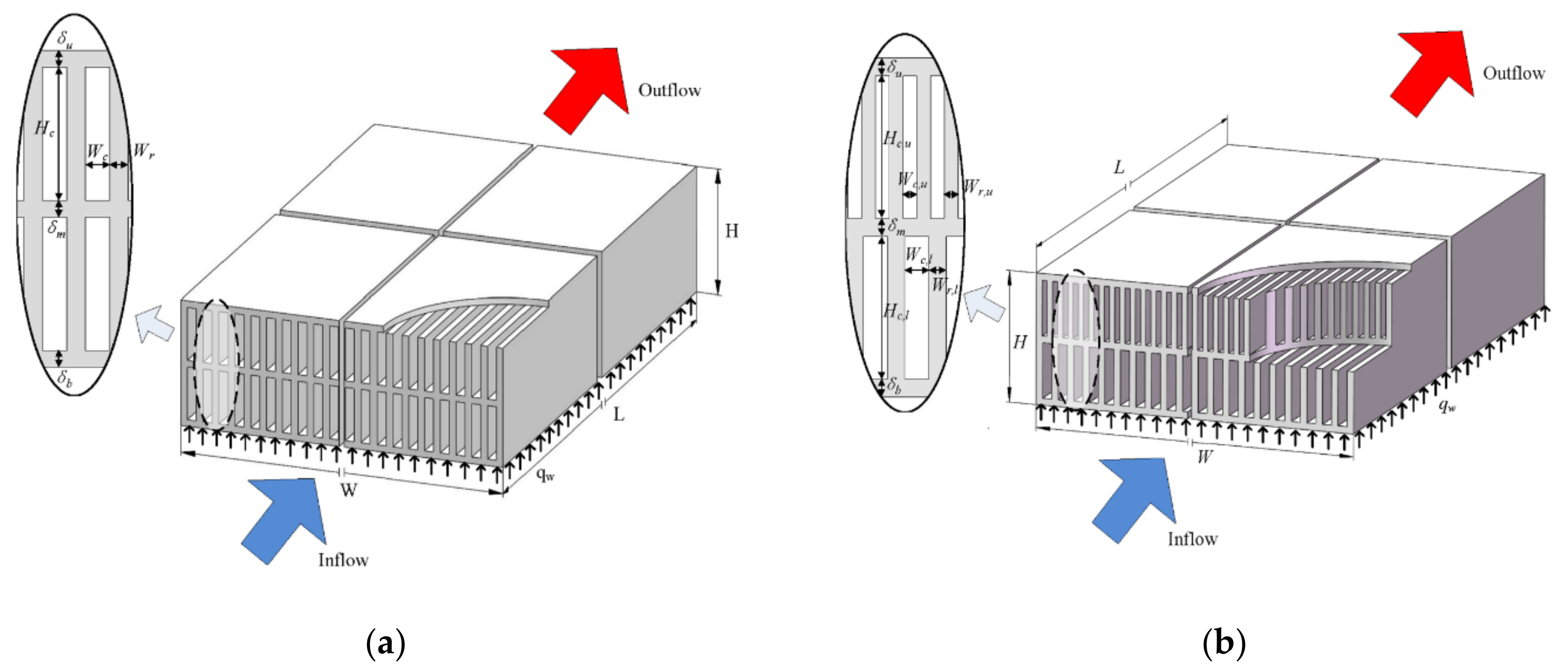
2.1. Traditional Double-Layer Microchannel Heat Sink

The traditional DMHS is shown in Figure 1a. The upper and lower layers contain the same geometry. It is assumed that the flow in the double layers is evenly distributed. Table 1 describes the detailed geometry of a conventional DMHS.

2.2. Definition of the Proposed Double-Layer Microchannel Sink

Figure 1b shows the geometry of the proposed DMHS (Case2). Compared with the traditional DMHS, the significant difference is that the geometric parameters of the upper and lower layers are different. Among them, the number of fins in upper layer is more than that in the lower layer, but the fin thickness is thin, while the number of fins in lower layer is less and the thickness is larger than that of upper channel fins, i.e.,
W c , u < W c , l   ,   W r , u < W r , l
among them, W c , u   ,   W r , u , W c , l ,   W r , l are channel width of the upper layer, fin thickness of the upper layer, channel width of the lower layer, and fin thickness of the lower layer, respectively.
In order to compare with the traditional DMHS, case2 is composed of the upper layer of case0 and the lower layer of case1. In order to study the influence of changing the height of upper and lower layers on the overall thermal performance and pressure drop loss, case3 was designed. The geometric parameters of the two cases are given in Table 2.
Other structural parameters are the same as the traditional DMHS. Because the upper and lower layers have different geometric structures, the pressure loss generated by the upper channel is large if the flow rates are equal amid the upper and lower layer. Through this design, more coolant flow is forced toward the lower layer, and the upper and lower layers contain different flow rates.
The flow direction in the upper and lower layer in this study is the same.

2.3. Material Selection

Silicon material has high thermal conductivity and hardness, and silicon-based microchannel sink has been widely used. Therefore, in this paper, silicon is chosen as the basic material of the heat sink, the contact thermal resistance is ignored, and the outer wall of the heat sink is set for thermal insulation. Deionized water is used as the coolant because of its excellent physical and thermodynamic properties. The detailed parameters are shown in Table 3.

3. Analysis and Simulation Process

3.1. Assumptions and Governing Formulas

In this study, Reynolds number is controlled below 700 and relevant assumptions follow [61]:
  • The fluid flow is assumed incompressible and laminar, and steady state prevails.
  • The influence of gravity effect and radiation is ignored.
  • The thermophysical properties of fluid and solid materials are constant.
  • The influence of viscous dissipation is ignored.
  • No slip conditions occur at the fluid/solid interface.
  • For the traditional double-layer microchannel heat sink, it is assumed that the flow of each channel is evenly distributed.
The associated governing equations follow [60,61,62]:
Mass conservation equation:
u x + v y + w z = 0
where, u , v , and w   are the velocity components of the fluid along the x, y, and z axes.
Momentum equation:
ρ f ( u u x + v u y + w u z ) = μ f ( 2 u x 2 + 2 u y 2 + 2 u z 2 ) p x
ρ f ( u v x + v v y + w v z ) = μ f ( 2 v x 2 + 2 v y 2 + 2 v z 2 ) p y
ρ f ( u w x + v w y + w w z ) = μ f ( 2 w x 2 + 2 w y 2 + 2 w z 2 ) p z
where ρ f and μ f are the density and dynamic viscosity of the water coolant, respectively, and p is the fluid pressure.
For the fluid domain, the energy equation is:
ρ f c p , f ( u T x + v T y + w T z ) = k f ( 2 T x 2 + 2 T y 2 + 2 T z 2 )
where C p , f and k f are specific heat capacity and thermal conductivity of the fluid, respectively.
For the solid domain of silicon, the energy equation is:
k s ( 2 T x 2 + 2 T y 2 + 2 T z 2 ) = 0
where k s is the heat conductivity of the solid silicon.
The boundary conditions are set as follows.
Inlet in upper layer microchannels:
u = u u , i n   ,   v = 0   ,   w = 0   ,   T = T i n
Inlet in lower layer microchannels:
u = u l , i n   ,   v = 0   ,   w = 0   ,   T = T i n
For traditional double-layer microchannels:
u u , i n = u l , i n = Q V / N
For the proposed double-layer microchannel:
u u , i n = Q u / N u
u l , i n = Q l / N l
where u u , i n and u l , i n are the velocities of the upper and lower channel, respectively; Q V is the total flow rate; N is the total number of DMHS channels; Q u   and Q l are the volumetric flow rates in the upper and the lower channel; N u and N l are the number of the upper and lower layers of the proposed double-layer microchannel; and T i n   is the inlet fluid temperature.
Outlet setting:
p = p o u t ,   T t o t a l = 300 K
where p o u t is the pressure outlet, and the reference pressure is the standard atmospheric pressure; and T t o t a l is defined as the total temperature at the outlet boundary.
Interface between solid and coolant:
u = 0 ,   v = 0 ,   w = 0 ,   T s = T f
k f T f n = k s T s n
Substrate bottom in DMHS:
q w = c o n s tan t = k s T s n
Other solid walls and planes of symmetry:
T s n = 0
where n is the normal unit vector of the solid wall; T f and T s are the average temperatures of the solid and working fluid, respectively; and q w is the constant heat flux applied to the floor.
The pumping power of the DMHS system:
P = u i n A c Δ p N = Q u Δ p
where P is total pumping power; A c is the total cross-sectional area of the channels; and Δ p represents the pressure drop loss of DMHS.
The Reynolds number at the inlet is defined as:
Re = ρ u i n D h μ
where ρ is the working fluid density; u i n represents the average velocity at the inlet; and D h is the equivalent hydraulic diameter of the inlet.
The friction factor is defined as:
f = Δ p 2 ρ f u i n 2 D h L
where L is the length of the microchannel in DMHS.
The total thermal resistance is one of the important indexes of heat transfer performance; it is defined as:
R t h = T w , m a x T i n q w A b
where T w , m a x is the highest temperature of the bottom plate and A b represents the floor area of the computational domain.
The average Nusselt number of channels is defined by the following equations:
N u = h D h k f
h = q w A c A c ( T f T b )
T f = T i n + T o u t 2
where h is the average convective heat transfer coefficient; T f is the average temperature of the fluid; T b is the average wall temperature; T o u t is the outlet temperature of the fluid; and A c is the total area of coupled wall.

3.2. Simulation Domain

In this paper, the length (L) of the DMHS is selected as 15 mm. To reduce the computational loading, the simulation considers the periodicity and symmetry conditions as shown in Figure 1. The length of inlet and outlet section is set as L i n = L o u t = 6 mm (>>10 Dh), the calculation domain of case0 is 0.08 mm (width) × 0.95 mm (height) × 27 mm (length). For case1, it is 0.12 mm × 0.95 mm × 27 mm and for case2 it is 0.24 mm × 0.95 mm × 27 mm, as indicated in Figure 2.

3.3. Simulation Methods

In this paper, four kinds of structures are simulated. The bottom of the fin is uniformly heated with constant heat flux q w = 2,000,000 W/m2. Symmetry prevails at the left and right sides of the calculation domain, and the other outer walls are adiabatic. The fluid temperature of the inlet is set at 300 K; pressure outlet condition ( p   = 0) is used at the outlet.
FLUENT 18.2 is used for simulation and the SIMPLEC (semi-implicit method for pressure linked equations) algorithm is selected to couple pressure and velocity. The momentum and energy equations are discretized by the second-order upwind difference method. During the iteration processes, a convergence criterion is set only when residuals of energy, velocities, and continuity fall below 10−8, 10−6, 10−4, correspondingly.

3.4. Study of Grid Independence

ICEM is used to divide the tetrahedral mesh. Three kinds of meshes are set up to check the mesh independence with inlet velocity of 0.75 m/s. The number of grid lines in x, y, and z directions is mesh I (117 × 134 × 604), mesh II (97 × 120 × 542), and mesh III (83 × 96 × 452). The pressure drop ( Δ p ) at the inlet and the maximum temperature ( T m a x ) on the substrate are simulated. As shown in Table 4, mesh I is regarded as the baseline. The deviation of T m a x and Δ p for mesh II are 0.003% and 0.22%, respectively, and that of mesh III are 0.02% and 0.68%, respectively. It shows that the number of grids has little effect on the simulation. Considering the accuracy and calculation speed, mesh II is selected for subsequent simulation.

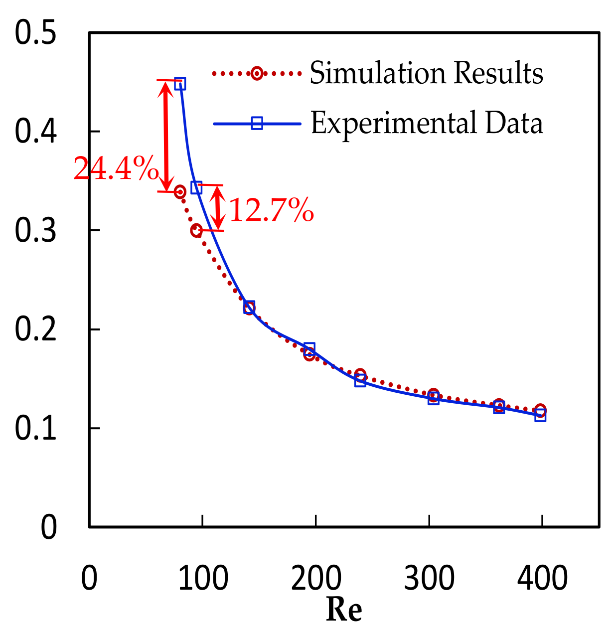
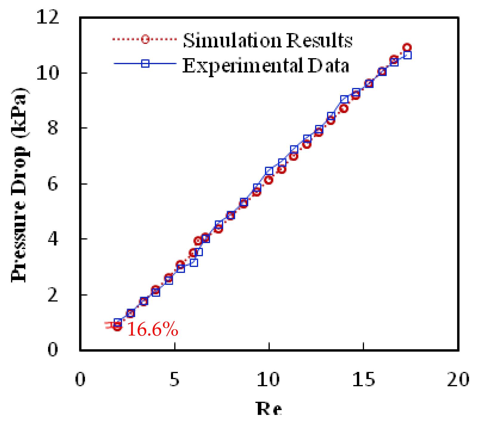
3.5. Model Validation

In order to further verify the reliability of the model, the differences between the prediction and the experimental results are compared by referring to the experimental data in the existing literature. Koichiro Kawano et al. [67] conducted experiments using water as cooling medium at room temperature with a supplied heat flux of 100 W/cm2, and a Reynolds number between 0 and 400. The corresponding microchannel width is 57 μm and the channel height is 180 μm. The comparison of simulation and experimental data is shown in Figure 3, and it is found that the simulation results are in good agreement with the experimental data. Analogous agreement with another microchannel heat sink carried out by Tuckerman and Pease [3] is listed in Table 5. It is found that the maximum difference between the simulation results and the experimental data is only 0.09%. Yet, the simulation is also carried out to compare the experimental pressure drop by Papautsky et al. [68]. As shown in Figure 4, the simulation is in line with the measurements. Through the foregoing validations, the proposed simulation is substantiated accordingly.

4. Results and Discussion

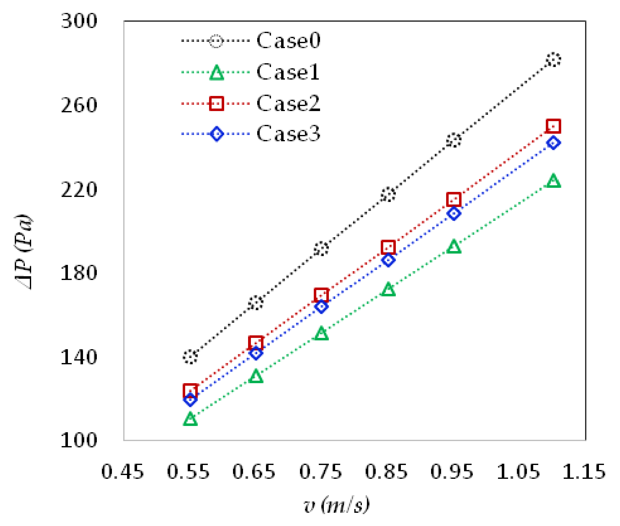
4.1. Pressure Drop Loss and Corresponding Pumping Power

There are four designs of microchannels in this study. The size of upper and lower microchannels in case0 and case1 are the same, and their total cross section area is 4.8 mm2 and 4 mm2, respectively. Case2 and case3 have different sizes of upper and lower microchannels, and the cross-sectional area is 4 mm2 and 4.3 mm2, respectively. Figure 5 shows the trend of pressure drop under different inlet velocities, and the change in pressure drop of four different cases is similar. Although case 0 has the largest cross-sectional area, it contains a larger shape resistance and friction due to the smaller size of channel spacing. Hence, case0 shows the largest pressure drop for inlet velocity. Yet the difference in pressure drop for case0 relative to other cases is slightly increased with the rise of inlet velocity. On the contrary, case1 has the smallest pressure loss. The size of the upper channel of case2 is the same as that of case0. This is because the size of the lower channel is the same as that of case1, and the cross-sectional area is between them. Hence, the pressure drop is also between case0 and case1. When the height of case2 is adjusted to be in-between the upper and lower channels, the pressured drop at the lower channel increases to balance the decline of pressure drop at the upper channel decreases. Eventually, it makes the overall pressure drop decrease significantly.
The relationship between pumping power and total thermal resistance is shown in Figure 6. Higher pumping power yields lower thermal resistance for all cases. It can be clearly seen that the proposed microchannel heat sink contains a lower thermal resistance under the same pumping power. In addition, comparing with the results of caes3 and case2, a higher height of the lower channel leads to a lower thermal resistance. Moreover, this phenomenon becomes more pronounced at a higher supplied pumping power.

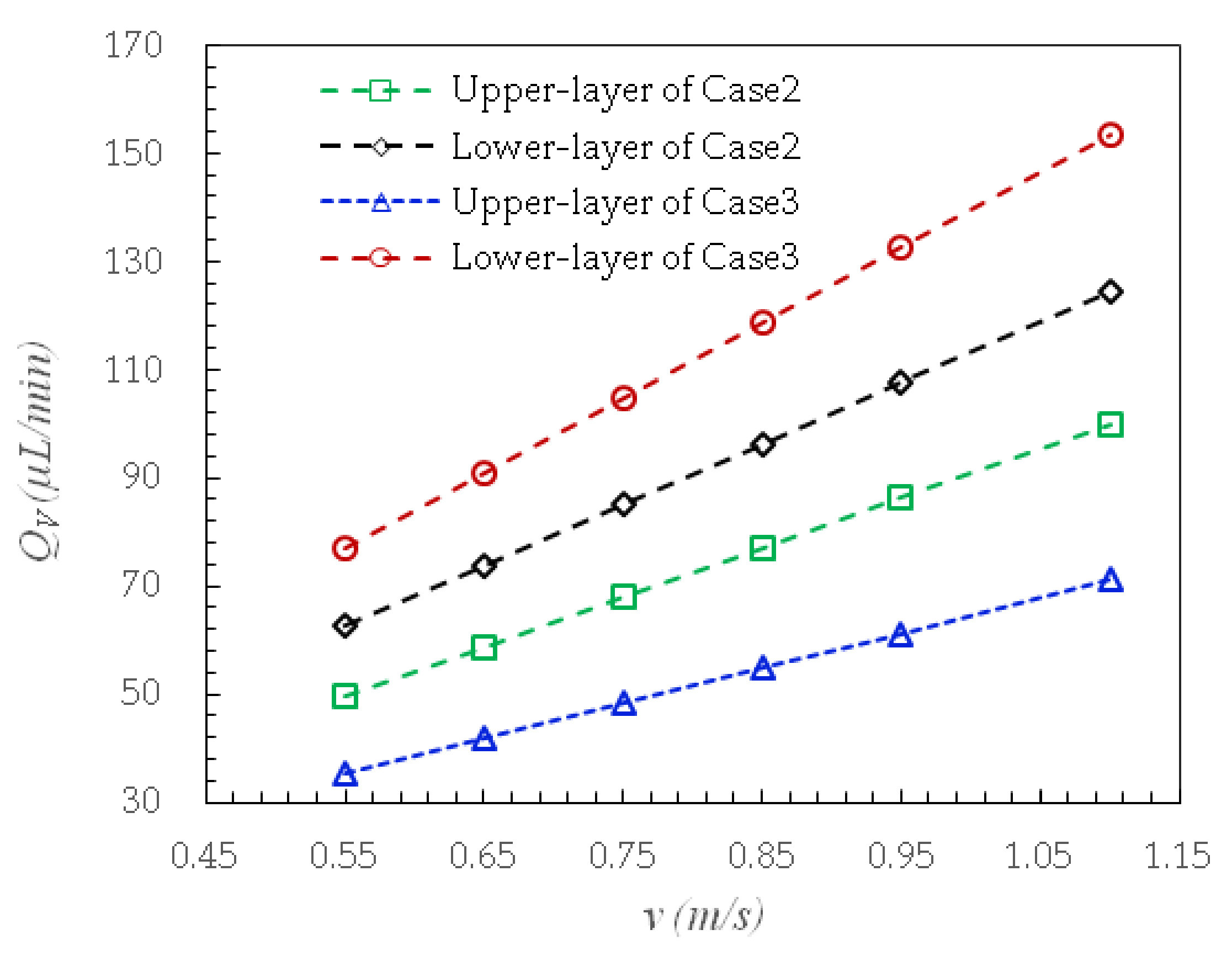
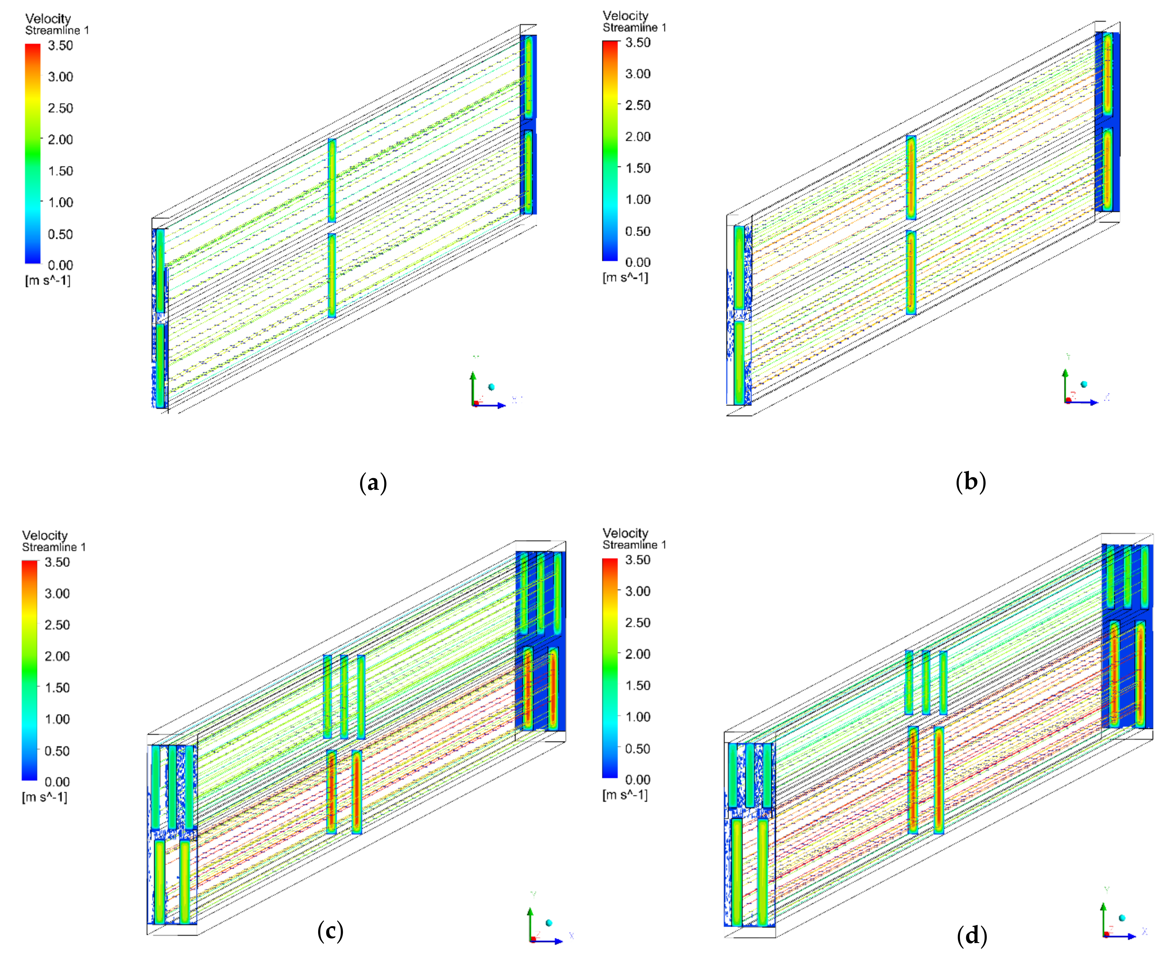
4.2. Flow Distribution and Velocity Characteristics

In order to understand the mechanism of the proposed structure, further analysis is carried out to examine the flow rate distribution. Figure 7 shows the flow rate variation of the proposed heat sink subject to six flow rates. The results show that the proposed uneven structure can force more flow toward the lower layer, and the flow rate at the lower layer is thus greater than that in the upper layer. The flow ratio of case2 is between 1.245 and 1.261. Case3 has the same trend, but thanks to the increase of the height of the lower channel, the flow ratio of the lower and upper layers is larger, with the maximum flow ratio of 2.184 and the minimum of 2.156. The very slight decrease of the ratio with rising flow rate is due to the increase of the velocity in both layers, which corresponds to substantial rise in friction in both layers and the increase of the inertial force of the fluid hinders the significant change of the flow ratio.
Figure 8 shows the velocity distribution at an inlet velocity of 0.75 m/s. A series of profiles of velocity amplitude at the inlet, outlet, and middle position of the channel are given to highlight the velocity distribution and gradient along the microchannel of each heat sink structure. A streamline diagram is added to further illustrate the change trend. It can be seen from the figure that the velocity reaches the maximum at the center line of the channel, and this is even more prominent in the proposed microchannel heat sink. The flow in the upper and lower layers of case0 and case1 is uniform, and the velocity distribution in the upper and lower layers is the same. However, the velocity in the lower layer of case2 and case3 is higher than that in the upper layer, and the maximum velocities are 2.55 m/s, 3.11 m/s, 3.45 m/s, and 3.35 m/s, respectively. The velocity near the channel center line is much higher than that near the wall, which directly leads to the increase of pressure drop, resulting in a large velocity gradient near the wall, resulting in the increase of pressure drop loss and pumping power. Note that case2 has the same lower structure as that of case1, but it has higher flow velocity, pressure drops, and pumping power. This is because of a larger channel height and accordingly a larger flow area in the lower layer of case3. Hence, the flow rate decreases and the pressure drop decreases accordingly. However, due to the higher flow rate in the lower layer, the thermal resistance decreases. In addition, it can be seen from the flow trace of the four designs that the flow pattern in the double-layer microchannel is laminar because the Reynolds number is in the range of 80~410.

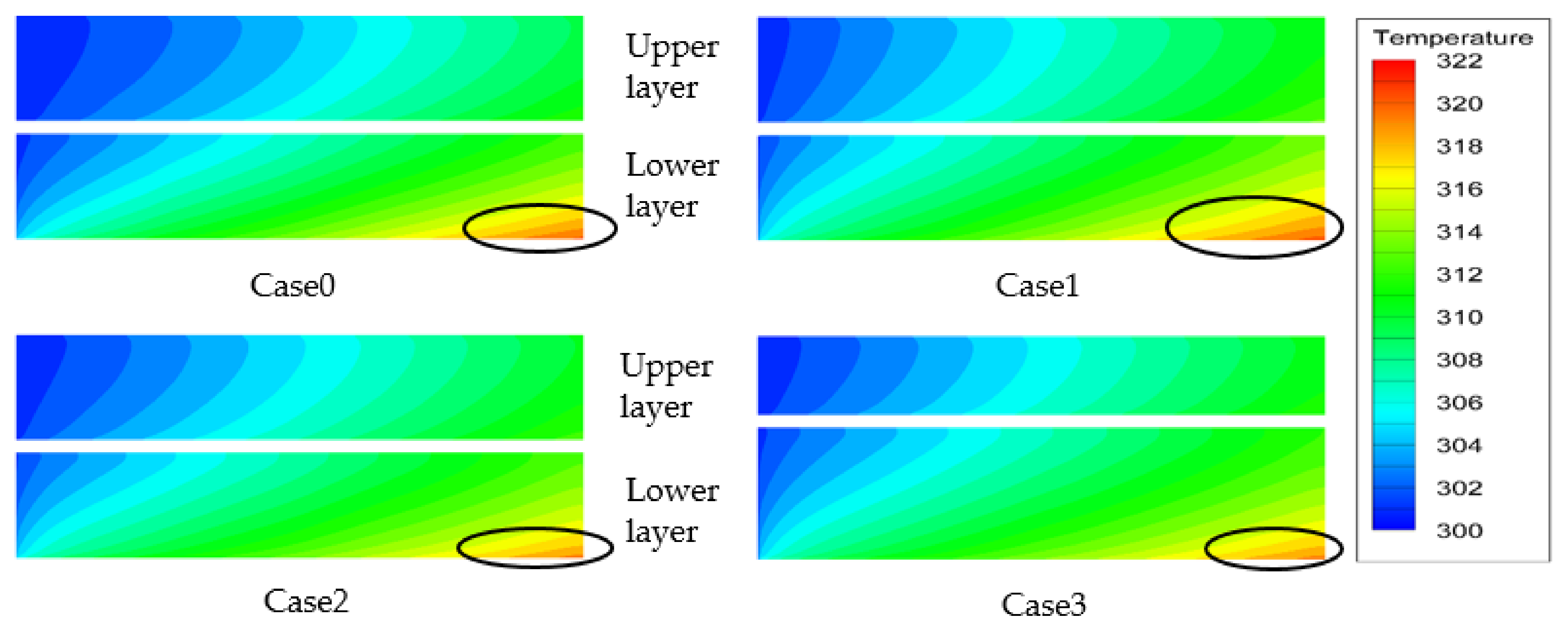
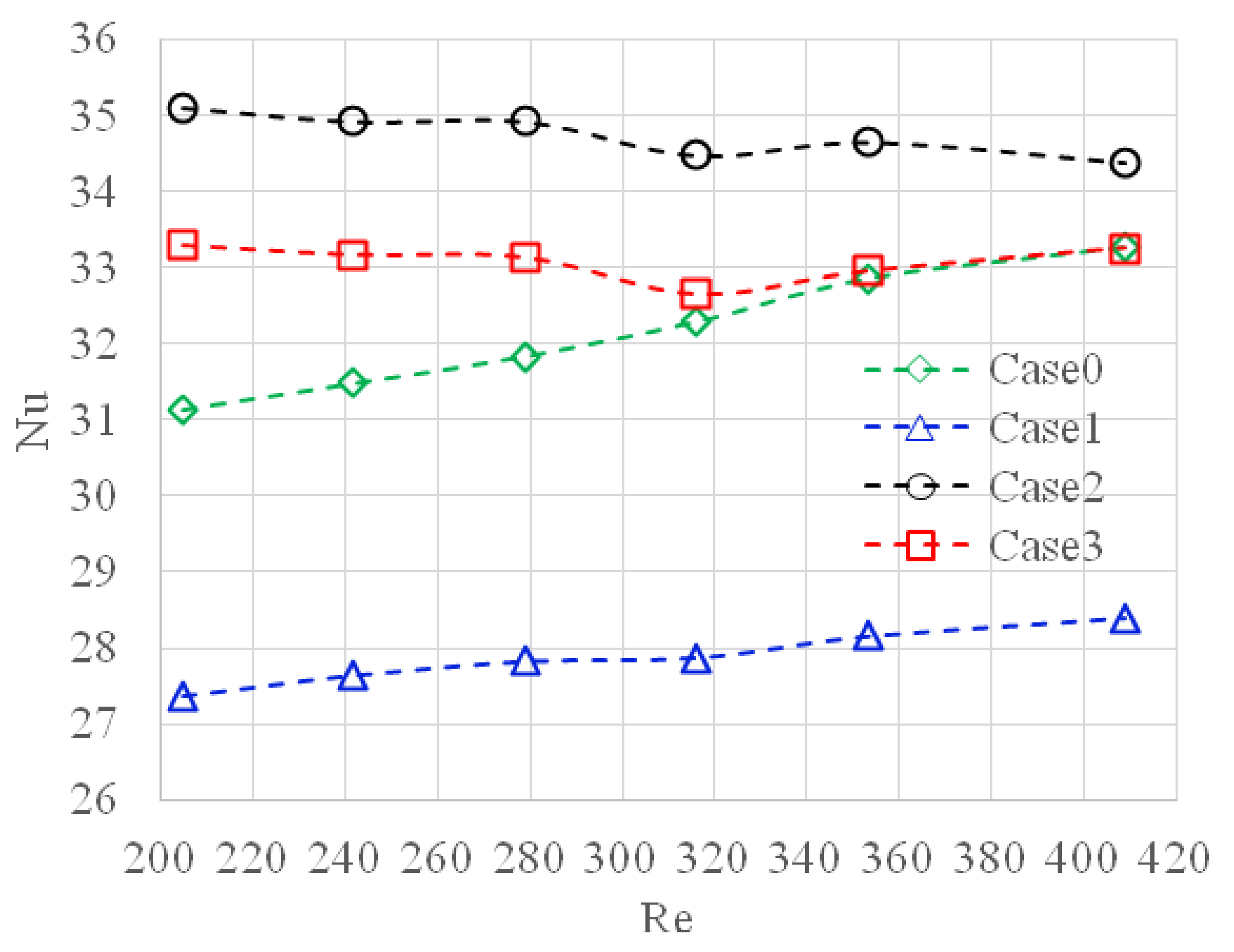
4.3. Heat Transfer Characteristics

Figure 9 shows the temperature distribution and thermal gradient of the fluid in the microchannel of the four different cases, the temperature unit is Kelvin (K), and the inlet flow velocity is u i n = 0.75 m/s. For all four cases, the average temperature of the lower inlet is significantly higher than that of the upper inlet, suggesting favorable cooling due to entraining more liquid flow toward the lower layer. This also means that the coolant in the upper channel has considerable potential cooling capacity, and the maximum temperature is moved farther downstream in the lower channel. Compared with the two traditional microchannel sinks, case0 has a smaller area of high temperature than that of case1, which is associated with more surface area to facilitate higher cooling capacity. Comparing the proposed designs to the traditional DMHS, a more uniform temperature distribution prevails in the proposed design, both in the upper and lower channel. In fact, the average temperature of the upper layer fluid of the proposed DMHS is slightly higher than that of the transitional one while the lower layer fluid temperature region of the proposed design is smaller. Yet in summary, the average temperature of the proposed design is lower than that of the traditional double-layer microchannel heat sink. The reason for this phenomenon is that the pressure drop of the upper channel of the proposed DMHS is greater than that of the lower channel, thereby forcing more fluid toward the lower channel. The higher temperature difference between the fluid and the substrate makes the lower layer of the proposed microchannel heat sink have a superior cooling performance.
In order to further analyze the heat dissipation of the substrate, Figure 10 shows the temperature distribution on the substrate of four kinds of DMHSs when u i n = 0.75 m/s. The maximum temperatures of the four cases are 321.04, 321.29, 320.33, and 320.23 K. In terms of thermal performance, the four cases have some similar characteristics. The temperature increases gradually from inlet to outlet; the highest temperature appears at the outlet, and the temperature difference is larger along the flow direction. One of the main purposes of the microchannel heat sink is to reduce the maximum temperature on the substrate heat source. It can be clearly seen from the figure that the traditional microchannel heat sink case0 and case1 have relatively high temperature due to the uniform flow distribution in the upper and lower layers. The heat dissipation area of case0 is larger than that of case1, so the high temperature area of case0 is slightly lower than that of case1, and the highest temperature is also smaller than that of case1. Case2 and case3 contain uneven design in upper and lower layer to entrain more liquid flow toward the lower layer. Hence, both cases significantly reduce the maximum temperature of the substrate. Between them, case2 has the lowest maximum temperature. Case 3 increases the height of the lower channel, further increasing the flow rate of the lower fluid, but is unable to further reduce the maximum temperature. This is because it contains a lower heat transfer coefficient due to a comparatively large hydraulic diameter.

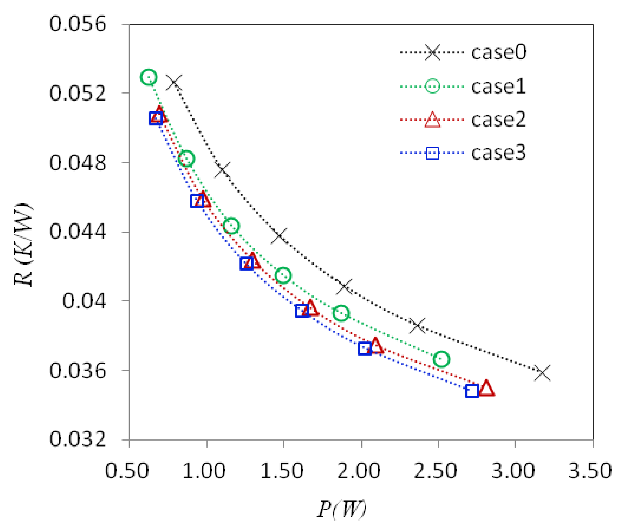
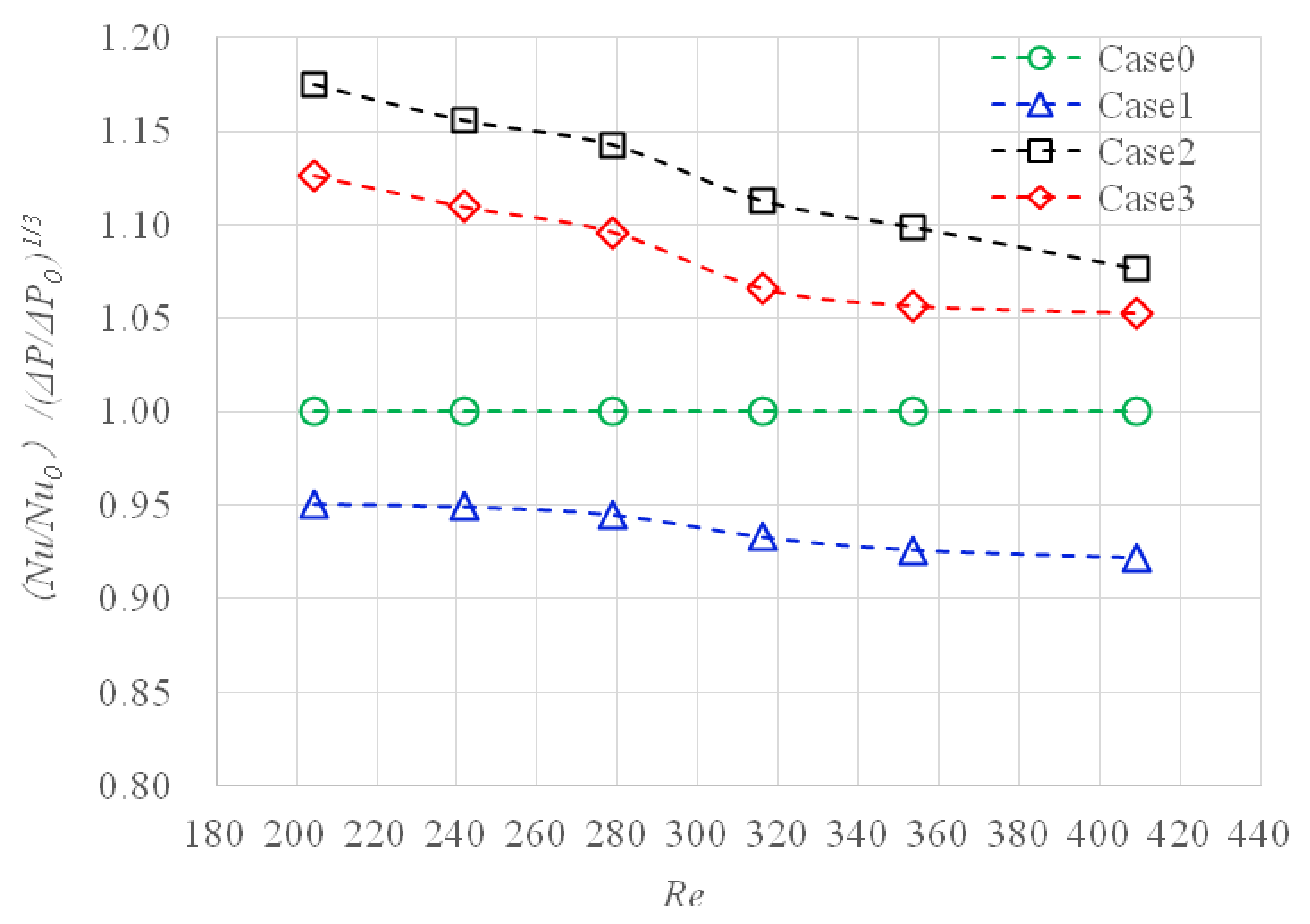
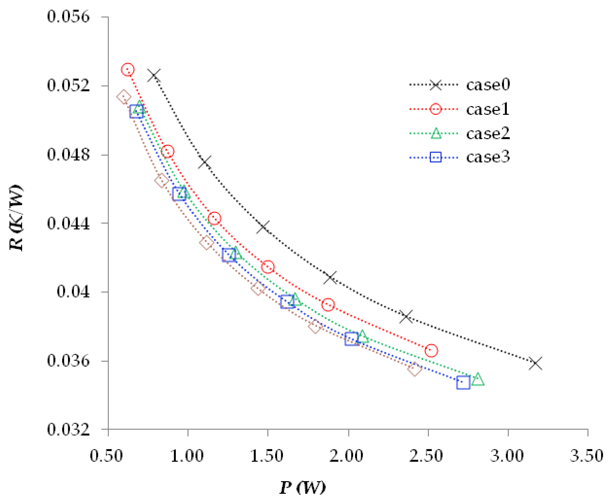
4.4. Overall Thermal Performance

To further evaluate the heat transfer intensity, Figure 11 shows the relationship between the average heat transfer Nusselt number and the inlet Reynolds number. As shown in Figure 11, with the increase of Reynolds number, the Nusselt number for case0 and case1 increases slightly. The slightly increasing trend of traditional designs is due to the contribution of the entrance region. On the other hand, despite this trend, the average Nusselt number of the proposed uneven designs is higher than those of the transitional one. It is found that the proposed design shows nearly invariant (or very slight decline) of Nusselt number against the Reynolds number. This is because the lower layer may exhibit a higher flow rate and higher heat transfer performance, but the upper layer features a smaller flow rate and a comparatively lower heat transfer performance. In summary, of these two effects, the proposed designs show an invariant change (or slight decline) of Nusselt number against the Reynolds number. This can be further made clear from case3, which contains a higher channel height at the lower layer. Hence, this design yields a much lower pressure drop, but also reduces the heat transfer performance due to a larger hydraulic diameter. As can be seen from Figure 11, case2 shows the best Nusselt number at the same Reynolds number. Specifically, when R e = 204.48, the Nusselt number of case2 is 35.10, which is about 5% higher than that of case3 and 13% higher than that of case1. Although the Nusselt number of case0 and case2 is significantly higher than that of case1 and case3 with the same structural characteristics, it also contains higher pressure drop penalty.
In order to quantify the overall performance of different cases, Gee and Webb [69] proposed the thermal performance factor ( N u / N u 0 ) / ( Δ p / Δ p 0 ) 1 / 3 to evaluate the overall heat transfer performance and the pressure drop. Hence, the concept is adopted in this study for further evaluation of the microchannel sink. Among them, ( Δ p / Δ p 0 ) 1 / 3 directly indicates the increase of pressure drop, while   N u / N u 0 indicates the improvement of convective thermal performance. Based on this criterion, Gong et al. [9] used thermal performance factors to evaluate the thermal characteristics in microchannels for their simulations. Here, the Δ p 0 and N u 0 represent the pressure drop and Nusselt number of case0 at different Reynolds numbers, respectively.
As shown in Figure 12, the overall thermal performance factors of case1, case2, and case3 decrease with the increase of Reynolds number. It shows that with the increase of Reynolds number, the heat transfer performance of the three cases decreases. But overall, the overall thermal performance of case1 is obviously worse than that of case0, and the thermal performance factors of the two proposed DMHS are greater than 1, suggesting superior performance of the proposed design.

5. Optimization

Optimization Method

Response surface methodology (RSM) is a combination of mathematical, experimental design, and statistical techniques [70]. The technology uses reasonable experimental design to find the parameters that have significant response to the results, and uses a multiple quadratic regression equation to establish the mathematical model between independent and dependent variables, thereby finding the optimal structural parameters through the analysis of the regression equation. Rahimi-Gorji et al. [70] used response surface method (RSM) and numerical simulation method to optimize the geometry of microchannel sink, and achieved good results. The effectiveness of response surface method (RSM) in the structure optimization of a microchannel heat sink is proven. Zhou et al. [71] also used the response surface method (RSM) combined with finite volume method (FVM) to optimize the geometric parameters for a microchannel heat sink having sine wave structure. It was found that this method has the characteristics of high efficiency and accuracy, and has a wide application prospect for the optimization of irregular heat transfer structure. Practice has proved that using RSM can reduce the time needed to meet the goal, and saves resources accordingly. In this paper, CFD is used to replace the experiment and RSM is used to optimize the double-layer microchannel structure. A general second-order model is defined as [71]:
y = a 0 + i = 1 n a i x i + i = 1 n a i i x i 2 + i = 1 n j = 1 n a i j x i x j | i < j
where x i and x j are the design variables; a is the tuning parameter, where the subscript i represents the observation unit in the response observation; n is the number of the variables (n = 2, in this paper). Thus, the response surface y contains the linear, squared, and cross-product terms.
Many studies show that the relationship between pumping power and thermal resistance is essential in the practical engineering application of microchannel heat sinks. The present study combines the numerical simulation from CFD and RSM method to optimize the geometric parameters of a symmetrical element. The calculation domain is as the same as case2. The element size is 0.24 mm × 0.95 mm × 27 mm, and the thickness of top plate, base plate, and middle partition is 50 μm. The number ratio of the upper and lower channels is 3:2, and the upper and lower layers of the heat sink have fixed fin spacing of 80 and 120 μm, respectively. Taking the coolant inlet flow rate, lower channel width, lower channel height, and upper channel width as variables, and using the minimum thermal resistance when the pumping power is equal to 1.2W as the target, the variable range and variable size are shown in Table 6.
Use the following formula for normalization:
Z = x x ¯ Δ x ,   Δ x = x m a x x m i n 2
The normalized variables are shown in Table 7.
Central composite design (CCD) is the used most for response surface design experiment, which can efficiently estimate the first-order and second-order terms, to evaluate the nonlinear effects of factors. CCD is suitable for multifactor and multilevel experiments, and it can better fit the corresponding surface upon continuous variations. In this study, the central composite method was used to design the experimental case, and the items with significant impact on the response were found through the analysis of variance; the following quadratic regression equation of thermal resistance ( R t h ) and pumping power (P-P) was found:
y R t h × 10 3 = 45.857 4.230 A + 2.716 B + 0.659 C 0.234 D + 0.544 A 2 + 1.164 B 2 + 1.057 C 2 1.663 B C 0.743 B D
y p p = 1.0332 + 0.3241 A 0.3485 B 0.3475 C 0.0418 D 0.1165 A B 0.1117 A C + 0.2032 B C + 0.1008 B D
To find the optimal design constraints of the DMHS, one must consider the pumping power and space size as the design constraints. According to the analysis given above, the optimized mathematical model is formed as follows:
Find
Z = [A, B, C, D]
To minimize
f ( Z ) = y R t h
Subject to
y P - P = 1.2 1 < A , B , C , D < 1
The “fmincon” function of MATLAB software is used to solve constrained nonlinear programming. After ant-normalization and rounding the integer, the final results follow:
X = [ 0.75 , 38 , 54 , 500 ]
The optimized structure of the proposed DMHS is shown in Table 8.
The regression equation established by RSM shows that the most influential factors are the height of the lower channel ( H c , l ), the width of the upper channel ( W c , u ), and the width of the lower channel ( W c , l ), as far as thermal resistance and pumping power are concerned. The main effect of H c , l is not significant for thermal resistance and pumping power, but has a significant interaction effect with the width of the upper channel. The two factors W c , u and W c , l have significant effects on the response, and it is obvious that these two factors have opposite effects on the thermal resistance and pumping power. For the influence of thermal resistance, the coefficient of W c , u is more than four times that of W c , l , and for the influence of pumping power, there is little difference between them. Therefore, the overall performance can be improved by reducing W c , u to reduce the thermal resistance while increasing W c , l to control the pumping power. Figure 13 shows the relationship between the pumping power and total thermal resistance for case4 at six specified inlet speeds. Compared with the other cases, the thermal resistance decreases with the same pumping power after optimization. When the pump power is 1.2, the thermal resistance of case4 decreases by 9.42%, 4.23%, and 2.77%, when compared with case0, case1, and case2. The results prove the effectiveness of using the RSM method for optimization.

6. Conclusions

In this study, the authors propose a novel DMHS with different geometric dimensions between the upper layer and lower layer, which are compared with the traditional DMHS. The proposed novel heat sink contains dense and thin fins in the upper layer, and comparatively sparse and thick fins at the lower layer. The design can force more low-temperature fluid flow toward the lower layer, where the sparse fin structure offers lower pressure drop penalty. At the same time, the thicker fins at the lower layer ensure higher fin efficiency to facilitate high heat transfer. The design is examined via numerical simulation in detail, including the thermofluid characteristics, pumping power, flow characteristics, and thermal distribution of substrate and thermal performance factor. Based on the discussion, the following conclusions are drawn:
(1) By changing the structure of the upper and lower layers, and increasing the thickness of the lower fin and the width of the channel, more fluid can be forced to flow to the lower channel, thus improving the flow distribution of the fluid. Under the same pumping power, the thermal resistance of the dual unequal structure microchannel sink is smaller than that of the traditional microchannel sink. After optimization, compared with the traditional DMHS at the same pumping power, the thermal resistance of the proposed DMHS can be reduced by 9.42%.
(2) The maximum temperature of the substrate of all cases appears at the exit position, and the maximum temperature of the double-layer unequal structure microchannel sink is lower than that of the traditional microchannel sink. At the simulated Reynolds number, the temperature distribution in the lower layer of the double-layer unequal structure microchannel sink is better than that of the traditional microchannel sink, and the average temperature is lower.
(3) For the proposed DMHS, increasing the height of the lower layer can effectively reduce the pressure drop. Although it contains a lower thermal resistance at the same pump power, its performance is inferior to the case having the same height at the upper and lower layers.
(4) In general, the proposed DMHS shows a much higher Nusselt number than the transitional DMHS. When R e = 204.48, the Nusselt number for the proposed design is about 13% higher than that of the traditional DMHS. The overall thermal performance factor of the proposed DMHS is greater than 1, indicating that the overall heat dissipation performance of the proposed DMHS is better than that of the traditional DMHS.
(5) Compared with the traditional double-layer rectangular microchannel radiator, the proposed structure has better heat transfer performance at the same power conditions. Yet the design contains a simple structure that only manipulates fin thickness and fin spacing in the upper and lower layer. Hence, it can be manufactured easily in mass quantity. In addition, the proposed design outperforms those with a staggered structure, as described elsewhere [60,61,62], and the thermal performance factor of the proposed structure is much larger, especially for low Reynolds numbers.

Author Contributions

All the authors contributed effort to complete the paper. Y.-D.Z. prepared, simulated, and analyzed the data; C.-C.W., M.-R.C., J.-H.W. and K.-S.H. provided administration assistance. All authors have read and agreed to the published version of the manuscript.

Funding

This research was funded by Ministry of Science and Technology, Taiwan under grant number of 108-2221-E-009-058-MY3.

Institutional Review Board Statement

Not applicable.

Informed Consent Statement

Not applicable.

Data Availability Statement

Not applicable.

Acknowledgments

The authors acknowledge the support from Ministry of Economic Affairs, Taiwan.

Conflicts of Interest

The authors declare no conflict of interest.

Nomenclature

a tuning parameter
Absubstrate surface area of the calculation domain (m2)
Actotal area of coupled wall
C p , f specific heat capacity in the constant pressure of working fluid
Dhhydraulic diameter of each tunnel (m)
hconvective heat transfer coefficient
Hheight of the heat sink (mm)
H c , u height of upper channel (μm)
H c , l height of lower channel (μm)
k f ,   k s heat conductivity of heat transfer fluid and solid silicon (W/m⋅K)
Llength for the designed DMHS (mm)
Nnumber of channels
NuNusselt number
p pressure of the working fluid (Pa)
p o u t pressure of outlet (Pa)
Ppump power work for the required system (W)
q w heat flux from the substrate (W/m2)
Q V total volume flow rate (L/min)
Rthermal resistance (K/W)
ReReynolds number
R t h thermal resistance (K/W)
Ttemperature on the substrate of DMHS (K)
T b average temperature of coupled wall (K)
T i n temperature of coolant at the inlet of channels (K)
T t o t a l total temperature set at the outlet of channels (K)
T o u t temperature of coolant at the outlet of channels (K)
Tsaverage temperature of solid (K)
T f average temperature of fluid (K)
Wintegrated DMHS width (m)
W c , u width of upper channel (μm)
W c , l width of lower channel (μm)
W r , u thickness of upper fin (μm)
W r , l thickness of lower fin (μm)
W t distance between the central lines of adjacent tunnels
u, v, wfluid velocities along the x, y, and z directions
x, y, zspanwise, normal, and streamwise directions
Znormalized variable
Greek Symbols
Δ p pressure drop penalty (Pa)
δ u top plate thickness
δ m middle plate thickness
δ b substrate thickness
μ f fluid dynamic viscosity of working liquid (Pa⋅s)
ρ f density of working liquid (kg/m3)
Abbreviations
DHMSDouble-layer Microchannel Heat Sink
HMSMicrochannel Heat Sink
SHMSSingle-layer Microchannel Heat Sink
CFDComputational Fluid Dynamics
RSMResponse Surface Methodology
Aveaveraged value
Subscripts
c , l lower channel
c , u upper channel
cchannels in DMHS
llower
ininlet
maxmaximum
minminimum
uupper
r , l rib of the lower-layer
r , u rib of the upper-layer

References

  1. Schmidt, R.R.; Notohardjono, B.D. High-end server low-temperature cooling. IBM J. Res. Dev. 2002, 46, 739–751. [Google Scholar] [CrossRef]
  2. Tullius, J.F.; Vajtai, R.; Bayazitoglu, Y. A Review of Cooling in Microchannels. Heat Transf. Eng. 2011, 32, 527–541. [Google Scholar] [CrossRef]
  3. Tuckerman, D.; Pease, R. High-performance heat sinking for VLSI. IEEE Electron Device Lett. 1981, 2, 126–129. [Google Scholar] [CrossRef]
  4. Qu, W.; Mudawar, I. Experimental and numerical study of pressure drop and heat transfer in a single-phase micro-channel heat sink. Int. J. Heat Mass Transf. 2002, 45, 2549–2565. [Google Scholar] [CrossRef]
  5. Liu, D.; Garimella, S. Investigation of Liquid Flow in Microchannels. In Proceedings of the 8th AIAA/ASME Joint Thermophysics and Heat Transfer Conference, St. Louis, MO, USA, 24–26 June 2002; pp. 65–72. [Google Scholar]
  6. Dirker, J.; Meyer, J.P.; Garach, D.V. Inlet flow effects in micro-channels in the laminar and transitional regimes on single-phase heat transfer coefficients and friction factors. Int. J. Heat Mass Transf. 2014, 77, 612–626. [Google Scholar] [CrossRef] [Green Version]
  7. Tiselj, I.; Hetsroni, G.; Mavko, B.; Mosyak, A.; Pogrebnyak, E.; Segal, Z. Effect of axial conduction on the heat transfer in micro-channels. Int. J. Heat Mass Transf. 2004, 47, 2551–2565. [Google Scholar] [CrossRef]
  8. Lee, P.-S.; Garimella, S.V.; Liu, D. Investigation of heat transfer in rectangular microchannels. Int. J. Heat Mass Transf. 2005, 48, 1688–1704. [Google Scholar] [CrossRef] [Green Version]
  9. Gong, L.; Kota, K.; Tao, W.; Joshi, Y. Parametric Numerical Study of Flow and Heat Transfer in Microchannels with Wavy Walls. J. Heat Transf. 2011, 133, 051702. [Google Scholar] [CrossRef]
  10. Dehghan, M.; Valipour, M.S.; Saedodin, S. Analytical Study of Heat Flux Splitting in Micro-channels Filled with Porous Media. Transp. Porous Media 2015, 109, 571–587. [Google Scholar] [CrossRef]
  11. Deng, B.; Qiu, Y.; Kim, C.N. An improved porous medium model for microchannel heat sinks. Appl. Therm. Eng. 2010, 30, 2512–2517. [Google Scholar] [CrossRef]
  12. Xu, H.; Zhao, C.; Vafai, K. Analysis of double slip model for a partially filled porous microchannel—An exact solution. Eur. J. Mech. B/Fluids 2018, 68, 1–9. [Google Scholar] [CrossRef]
  13. Dehghan, M.; Valipour, M.S.; Saedodin, S. Conjugate Heat Transfer Inside Microchannels Filled with Porous Media: An Exact Solution. J. Thermophys. Heat Transf. 2016, 30, 814–824. [Google Scholar] [CrossRef]
  14. Xia, G.; Ma, D.; Zhai, Y.; Li, Y.; Liu, R.; Du, M. Experimental and numerical study of fluid flow and heat transfer characteristics in microchannel heat sink with complex structure. Energy Convers. Manag. 2015, 105, 848–857. [Google Scholar] [CrossRef]
  15. Xie, G.; Li, Y.; Zhang, F.; Sundén, B. Analysis of micro-channel heat sinks with rectangular-shaped flow obstructions. Numer. Heat Transf. Part A Appl. 2016, 69, 335–351. [Google Scholar] [CrossRef]
  16. Shen, H.; Wang, C.-C.; Xie, G. A parametric study on thermal performance of microchannel heat sinks with internally vertical bifurcations in laminar liquid flow. Int. J. Heat Mass Transf. 2018, 117, 487–497. [Google Scholar] [CrossRef]
  17. Lu, G.; Zhao, J.; Lin, L.; Wang, X.-D.; Yan, W.-M. A new scheme for reducing pressure drop and thermal resistance simultaneously in microchannel heat sinks with wavy porous fins. Int. J. Heat Mass Transf. 2017, 111, 1071–1078. [Google Scholar] [CrossRef]
  18. Dehghan, M.; Daneshipour, M.; Valipour, M.S.; Rafee, R.; Saedodin, S. Enhancing heat transfer in microchannel heat sinks using converging flow passages. Energy Convers. Manag. 2015, 92, 244–250. [Google Scholar] [CrossRef]
  19. Wang, H.; Chen, Z.; Gao, J. Influence of geometric parameters on flow and heat transfer performance of micro-channel heat sinks. Appl. Therm. Eng. 2016, 107, 870–879. [Google Scholar] [CrossRef]
  20. Bejan, A.; Almogbel, M. Constructal T-shaped fins. Int. J. Heat Mass Transf. 2000, 43, 2101–2115. [Google Scholar] [CrossRef]
  21. Almogbel, M.A. Constructal tree-shaped fins. Int. J. Therm. Sci. 2005, 44, 342–348. [Google Scholar] [CrossRef]
  22. Lorenzini, G.; Rocha, L.A.O. Constructal design of Y-shaped assembly of fins. Int. J. Heat Mass Transf. 2006, 49, 4552–4557. [Google Scholar] [CrossRef]
  23. Kim, D.-K. Thermal optimization of branched-fin heat sinks subject to a parallel flow. Int. J. Heat Mass Transf. 2014, 77, 278–287. [Google Scholar] [CrossRef]
  24. Xie, G.; Shen, H.; Wang, C.-C. Parametric study on thermal performance of microchannel heat sinks with internal vertical Y-shaped bifurcations. Int. J. Heat Mass Transf. 2015, 90, 948–958. [Google Scholar] [CrossRef]
  25. Li, Y.; Zhang, F.; Sunden, B.; Xie, G. Laminar thermal performance of microchannel heat sinks with constructal vertical Y-shaped bifurcation plates. Appl. Therm. Eng. 2014, 73, 185–195. [Google Scholar] [CrossRef]
  26. Vafai, K.; Zhu, L. Analysis of two-layered micro-channel heat sink concept in electronic cooling. Int. J. Heat Mass Transf. 1999, 42, 2287–2297. [Google Scholar] [CrossRef]
  27. Vafai, K.; Zhu, L. Multi-Layered Micro-Channel Heat Sink, Devices and Systems Incorporating Same. U.S. Patent 6,675,875, 13 January 2004. [Google Scholar]
  28. Vafai, K.; Khaled, A.-R. Analysis of flexible microchannel heat sink systems. Int. J. Heat Mass Transf. 2005, 48, 1739–1746. [Google Scholar] [CrossRef]
  29. Khaled, A.-R.; Vafai, K. Control of exit flow and thermal conditions using two-layered thin films supported by flexible complex seals. Int. J. Heat Mass Transf. 2004, 47, 1599–1611. [Google Scholar] [CrossRef]
  30. Khaled, A.-R.; Vafai, K. Cooling augmentation using microchannels with rotatable separating plates. Int. J. Heat Mass Transf. 2011, 54, 3732–3739. [Google Scholar] [CrossRef]
  31. Lu, S.; Vafai, K. A comparative analysis of innovative microchannel heat sinks for electronic cooling. Int. Commun. Heat Mass Transf. 2016, 76, 271–284. [Google Scholar] [CrossRef]
  32. Saidi, M.H.; Khiabani, R.H. Forced Convective Heat Transfer in Parallel Flow Multilayer Microchannels. J. Heat Transf. 2006, 129, 1230–1236. [Google Scholar] [CrossRef]
  33. Levac, M.L.-J.; Soliman, H.M.; Ormiston, S.J. Three-dimensional analysis of fluid flow and heat transfer in single- and two-layered micro-channel heat sinks. Heat Mass Transf. 2011, 47, 1375–1383. [Google Scholar] [CrossRef]
  34. Xie, G.; Liu, Y.; Sundén, B.; Zhang, W.; Zhao, J. Numerical Investigation of Heat Transfer and Pressure Loss of Double-Layer Microchannels for Chip Liquid Cooling. In Proceedings of the Heat Transfer Enhancement for Practical Applications; Fire and Combustion; Multi-Phase Systems; Heat Transfer in Electronic Equipment; Low Temperature Heat Transfer, Rio Grande, PR, USA, 8–12 July 2012; Volume 2, pp. 575–583. [Google Scholar]
  35. Xie, G.; Liu, Y.; Sunden, B.; Zhang, W. Computational Study and Optimization of Laminar Heat Transfer and Pressure Loss of Double-Layer Microchannels for Chip Liquid Cooling. J. Therm. Sci. Eng. Appl. 2013, 5, 011004. [Google Scholar] [CrossRef]
  36. Wong, K.-C.; Muezzin, F.N.A. Heat transfer of a parallel flow two-layered microchannel heat sink. Int. Commun. Heat Mass Transf. 2013, 49, 136–140. [Google Scholar] [CrossRef]
  37. Hung, T.-C.; Yan, W.-M.; Li, W.-P. Analysis of heat transfer characteristics of double-layered microchannel heat sink. Int. J. Heat Mass Transf. 2012, 55, 3090–3099. [Google Scholar] [CrossRef]
  38. Hung, T.-C.; Yan, W.-M.; Wang, X.-D.; Huang, Y.-X. Optimal design of geometric parameters of double-layered microchannel heat sinks. Int. J. Heat Mass Transf. 2012, 55, 3262–3272. [Google Scholar] [CrossRef]
  39. Lin, L.; Chen, Y.-Y.; Zhang, X.-X.; Wang, X.-D. Optimization of geometry and flow rate distribution for double-layer microchannel heat sink. Int. J. Therm. Sci. 2014, 78, 158–168. [Google Scholar] [CrossRef]
  40. Wu, J.; Zhao, J.; Tseng, K. Parametric study on the performance of double-layered microchannels heat sink. Energy Convers. Manag. 2014, 80, 550–560. [Google Scholar] [CrossRef]
  41. Leng, C.; Wang, X.-D.; Wang, T.-H.; Yan, W.-M. Optimization of thermal resistance and bottom wall temperature uniformity for double-layered microchannel heat sink. Energy Convers. Manag. 2015, 93, 141–150. [Google Scholar] [CrossRef]
  42. Sakanova, A.; Yin, S.; Zhao, J.; Wu, J.; Leong, K. Optimization and comparison of double-layer and double-side micro-channel heat sinks with nanofluid for power electronics cooling. Appl. Therm. Eng. 2014, 65, 124–134. [Google Scholar] [CrossRef]
  43. Cheng, Y. Numerical simulation of stacked microchannel heat sink with mixing-enhanced passive structure. Int. Commun. Heat Mass Transf. 2007, 34, 295–303. [Google Scholar] [CrossRef]
  44. Dixit, P.; Lin, N.; Miao, J.; Wong, W.K.; Choon, T.K. Silicon nanopillars based 3D stacked microchannel heat sinks concept for enhanced heat dissipation applications in MEMS packaging. Sens. Actuators A Phys. 2008, 141, 685–694. [Google Scholar] [CrossRef]
  45. Morshed, A.K.M.M.; Khan, J.A. Numerical Analysis of Single Phase Multi Layered Micro-Channel Heat Sink with Inter-Connects Between Vertical Channels. In Proceedings of the 2010 14th International Heat Transfer Conference, Washington, WA, USA, 8–13 August 2010; Volume 6, pp. 133–140. [Google Scholar]
  46. Liu, Y.L.; Lio, X.B.; Liu, W. Cooling behavior in a novel heat sink based on multilayer staggered honeycomb structure. In Proceedings of the Asme Micro/Nanoscale Heat and Mass Transfer International Conference; 2010; pp. 131–135. [Google Scholar]
  47. Sharma, D.; Singh, P.P.; Garg, H. Numerical Analysis of Trapezoidal Shape Double Layer Microchannel Heat Sink. Int. J. Mech. Ind. Eng. 2014, 3, 219–224. [Google Scholar] [CrossRef]
  48. Leng, C.; Wang, X.-D.; Wang, T.-H. An improved design of double-layered microchannel heat sink with truncated top channels. Appl. Therm. Eng. 2015, 79, 54–62. [Google Scholar] [CrossRef]
  49. Leng, C.; Wang, X.-D.; Wang, T.-H.; Yan, W.-M. Multi-parameter optimization of flow and heat transfer for a novel double-layered microchannel heat sink. Int. J. Heat Mass Transf. 2015, 84, 359–369. [Google Scholar] [CrossRef]
  50. Zhai, Y.; Xia, G.; Liu, X.; Wang, J. Characteristics of entropy generation and heat transfer in double-layered micro heat sinks with complex structure. Energy Convers. Manag. 2015, 103, 477–486. [Google Scholar] [CrossRef]
  51. Zhai, Y.; Li, Z.; Wang, H.; Xu, J. Thermodynamic analysis of the effect of channel geometry on heat transfer in double-layered microchannel heat sinks. Energy Convers. Manag. 2017, 143, 431–439. [Google Scholar] [CrossRef]
  52. Osanloo, B.; Mohammadi-Ahmar, A.; Solati, A.; Baghani, M. Performance enhancement of the double-layered micro-channel heat sink by use of tapered channels. Appl. Therm. Eng. 2016, 102, 1345–1354. [Google Scholar] [CrossRef]
  53. Wong, K.-C.; Ang, M.-L. Thermal hydraulic performance of a double-layer microchannel heat sink with channel contraction. Int. Commun. Heat Mass Transf. 2017, 81, 269–275. [Google Scholar] [CrossRef]
  54. Khodabandeh, E.; Rozati, S.A.; Joshaghani, M.; Akbari, O.A.; Akbari, S.; Toghraie, D. Thermal performance improvement in water nanofluid/GNP–SDBS in novel design of double-layer microchannel heat sink with sinusoidal cavities and rectangular ribs. J. Therm. Anal. Calorim. 2019, 136, 1333–1345. [Google Scholar] [CrossRef]
  55. Li, X.-Y.; Wang, S.-L.; Wang, X.-D.; Wang, T.-H. Selected porous-ribs design for performance improvement in double-layered microchannel heat sinks. Int. J. Therm. Sci. 2019, 137, 616–626. [Google Scholar] [CrossRef]
  56. Wang, S.-L.; Li, X.-Y.; Wang, X.-D.; Lu, G. Flow and heat transfer characteristics in double-layered microchannel heat sinks with porous fins. Int. Commun. Heat Mass Transf. 2018, 93, 41–47. [Google Scholar] [CrossRef]
  57. Huang, Y.; Xu, M.; Li, H.; Shen, S.; Ma, S. A Novel Double-layered Heat Sink for High Power Electronics. In Proceedings of the 2018 IEEE 20th Electronics Packaging Technology Conference (EPTC), Singapore, 4–7 December 2018; pp. 686–690. [Google Scholar]
  58. Salimpour, M.R.; Al-Sammarraie, A.T.; Forouzandeh, A.; Farzaneh, M. Constructal Design of Circular Multilayer Microchannel Heat Sinks. J. Therm. Sci. Eng. Appl. 2019, 11, 011001. [Google Scholar] [CrossRef]
  59. Kulkarni, K.; Khan, A.A.; Kim, K.-Y. Performance Analysis of Double-Layer Microchannel Heat Sink With Various Microchannel Shapes. Heat Transf. Res. 2018, 49, 349–368. [Google Scholar] [CrossRef]
  60. Shen, H.; Zhang, Y.; Wang, C.-C.; Xie, G. Comparative study for convective heat transfer of counter-flow wavy double-layer microchannel heat sinks in staggered arrangement. Appl. Therm. Eng. 2018, 137, 228–237. [Google Scholar] [CrossRef]
  61. Shen, H.; Xie, G.; Wang, C.-C. The numerical simulation with staggered alternation locations and multi-flow directions on the thermal performance of double-layer microchannel heat sinks. Appl. Therm. Eng. 2019, 163, 114332. [Google Scholar] [CrossRef]
  62. Shen, H.; Xie, G.; Wang, C.-C. Heat transfer and thermodynamic analysis by introducing multiple alternation structures into double-layer microchannel heat sinks. Int. J. Therm. Sci. 2019, 145, 105975. [Google Scholar] [CrossRef]
  63. Jalali, E.; Akbari, O.A.; Sarafraz, M.M.; Abbas, T.; Safaei, M.R. Heat Transfer of Oil/MWCNT Nanofluid Jet Injection Inside a Rectangular Microchannel. Symmetry 2019, 11, 757. [Google Scholar] [CrossRef] [Green Version]
  64. Dadsetani, R.; Sheikhzadeh, G.A.; Hajmohammadi, M.R.; Safaei, M.R. Introduce a novel configurationof microchannel andhigh-conductivity insertsfor cooling of disc-shaped electronic components. Int. J. Numer. Methods Heat Fluid Flow 2019, 30, 2845–2859. [Google Scholar] [CrossRef]
  65. Arasteh, H.; Mashayekhi, R.; Goodarzi, M.; Motaharpour, S.H.; Dahari, M.; Toghraie, D. Heat and fluid flow analysis of metal foam embedded in a double-layered sinusoidal heat sink under local thermal non-equilibrium condition using nanofluid. J. Therm. Anal. Calorim. 2019, 138, 1461–1476. [Google Scholar] [CrossRef]
  66. Mozaffari, M.; D’Orazio, A.; Karimipour, A.; Abdollahi, A.; Safaei, M.R. Lattice Boltzmann method to simulate convection heat transfer in a microchannel under heat flux Gravity and inclination angle on slip-velocity. Int. J. Numer. Method H 2019, 30, 3371–3398. [Google Scholar] [CrossRef]
  67. Kawano, K.; Sekimura, M.; Minakami, K.; Iwasaki, H.; Ishizuka, M. Development of Micro Channel Heat Exchanging. JSME Int. J. Ser. B 2001, 44, 592–598. [Google Scholar] [CrossRef] [Green Version]
  68. Papautsky, I.; Brazzle, J.; Ameel, T.; Frazier, A. Laminar fluid behavior in microchannels using micropolar fluid theory. Sens. Actuators A Phys. 1999, 73, 101–108. [Google Scholar] [CrossRef]
  69. Gee, D.; Webb, R. Forced convection heat transfer in helically rib-roughened tubes. Int. J. Heat Mass Transf. 1980, 23, 1127–1136. [Google Scholar] [CrossRef]
  70. Rahimi-Gorji, M.; Pourmehran, O.; Hatami, M.; Ganji, D.D. Statistical optimization of microchannel heat sink (MCHS) geometry cooled by different nanofluids using RSM analysis. Eur. Phys. J. Plus 2015, 130, 1–21. [Google Scholar] [CrossRef]
  71. Zhou, J.; Hatami, M.; Song, D.; Jing, D. Design of microchannel heat sink with wavy channel and its time-efficient optimization with combined RSM and FVM methods. Int. J. Heat Mass Transf. 2016, 103, 715–724. [Google Scholar] [CrossRef]
Figure 1. Schematic diagrams of the designed double-layer microchannel heat sink: (a) traditional double-layer microchannel heat sink and (b) proposed double-layer microchannel heat sink.
Energies 14 03585 g001
Figure 2. Simulation domain of different cases.
Energies 14 03585 g002
Figure 3. Validation results compared with rectangular MHSs by Kawano et al. [67].
Energies 14 03585 g003
Figure 4. Validation results for Re versus pressure drop based on experimental data [68].
Energies 14 03585 g004
Figure 5. Pressure drops of the four cases at different inlet velocities.
Energies 14 03585 g005
Figure 6. Total thermal resistance vs. pumping power of the four microchannel sinks.
Energies 14 03585 g006
Figure 7. Flow rates at the upper and lower layers for the two proposed heat sinks at different inlet velocities.
Energies 14 03585 g007
Figure 8. Velocity distribution of coolant ( u i n = 0.75 m/s) for (a) case0, (b) case1, (c) case2, and (d) case3.
Energies 14 03585 g008
Figure 9. Temperature distribution on the substrate of the four cases ( u i n = 0.75 m/s).
Energies 14 03585 g009
Figure 10. Temperature distribution on substrate of the four cases ( u i n = 0.75 m/s).
Energies 14 03585 g010
Figure 11. Variation of Nusselt number with Reynolds number for the different cases.
Energies 14 03585 g011
Figure 12. Relationship between thermal performance factor and Reynolds number.
Energies 14 03585 g012
Figure 13. Total thermal resistance of different pumping power of the four microchannel sinks after optimization.
Energies 14 03585 g013
Table 1. Structural parameters of traditional double-layer microchannel sink (unit: μm).
W r , u W c , u W r , l W c , l H c , u H c , l
Case040404040400400
Case170507050400400
Table 2. Structural parameters of the proposed double-layer microchannel sink (unit: μm).
W r , u W c , u W r , l W c , l H c , u H c , l
Case240407050400400
Case340407050300500
Table 3. Material selection and the corresponding physical properties.
Density
(kg/m3)
Specific Heat
(J/(kg⋅K))
Thermal Conductivity (W/m⋅K))Viscosity
(kg/m⋅s))
Purified Water998.241820.61.003 × 10−3
Silicon2330710148
Table 4. Grid independence study; u i n = 0.75 m/s.
Mesh IMesh IIMesh III
Max. Temp. (K)320.32320.33320.39
Pressure drop, Pa169.93169.56168.78
DifferenceBaseline0.003%
0.22%
0.02%
0.68%
Table 5. Validation results of present study with experimental data [3].
No.WrWcHcΔp (bar)Rth
Exp. DataSimulation DataDeviation
15644320150.1100.1090.91%
25545287170.1130.1130.00%
35050302310.0900.0900.00%
Table 6. Variable size range.
Parameters u i n   ( m / s ) W c , u   ( μ m ) W c , l   ( μ m ) H c , u   ( μ m )
Upper limit value ( x m a x )0.553040300
Average value ( x ¯ )0.654050400
Lower limit value ( x m i n )0.755060500
Table 7. Variable size range (after normalization).
Coded Factors (after Normalization) A   ( u i n ) B   ( W c , u ) C   ( W c , l ) D   ( H c , u )
Upper   limit   value   ( x m a x )1111
Average value ( x ¯ )0000
Lower   limit   value   ( x m i n )−1−1−1−1
Table 8. The optimized geometry parameters of the proposed double-layer microchannel heat sink.
W r , u W c , u W r , l W c , l H c , u H c , l
Case442386654300500
Publisher’s Note: MDPI stays neutral with regard to jurisdictional claims in published maps and institutional affiliations.

