1. Introduction
In recent years, due to the high use of the petrochemical industry, air pollution, and the serious greenhouse effect have caused more and more bad quality of human life. In order to improve the quality of life and reduce the greenhouse effect, the development and application of renewable energy sources have attracted the attention of all countries in the world, and governments of various countries have also been asked to carry out this issue reform and response plan to reduce the dependence on petrochemical materials [
1,
2]. Traditional automobiles and motorcycles not only consume a lot of oil but also are one of the main sources of greenhouse gases. Therefore, to meet the government policies of various countries, various alternative energy vehicles have been proposed, and electric vehicles are the most attractive. Besides, with the improvement of science and technology, the battery needs of electric vehicles must be small in size and easy to operate [
3]. With the characteristics of high operating voltage, high power density, lightweight, high cycle times, low environmental pollution, and good safety, the lithium-ion battery is the most widely used rechargeable battery nowadays [
4,
5,
6,
7,
8,
9,
10]. However, with the high power demand of the electric vehicle power system, the lithium-ion batteries must improve the voltage and capacity of the system through series and parallel connections. Due to the differences in internal impedance, self-discharge rate, and manufacturing process of a single battery, the voltage imbalance is easy to occur after the batteries are connected in series and parallel. Therefore, it is necessary to ensure that all units in the battery module are powered pool security [
11,
12,
13,
14,
15,
16,
17,
18].
Therefore, in the current battery management system research [
19,
20,
21,
22,
23,
24,
25,
26,
27,
28], most of the proposed battery management systems are used in series lithium-ion battery modules. However, in order to increase the capacity and high working voltage, most of the lithium-ion battery modules are series or parallel type, so the current battery management system cannot afford its functions. In this paper, a modular battery management system for an electric motorcycle is proposed. The system has fast balancing and protection function, which uses the signal processor as the main controller and is equipped with a battery monitoring chip of multiple batteries. It is capable of measuring the series and parallel type or monitor multiple independent battery modules by one control system. The battery management system can accurately measure the battery voltage, charge current, discharge current, and temperatures. These data are then transmitted to the mixed-signal processor for battery module monitoring, balancing, and protection. Finally, the testing results validate the modular battery measurement system proposed in this paper. It has the functions of managing the battery balancing of each cell in the battery module, overcharge and over-discharge of the battery module, temperature protection, and control. The system has the potential to be applied in the battery management system of an electric motorcycle.
2. System Structure
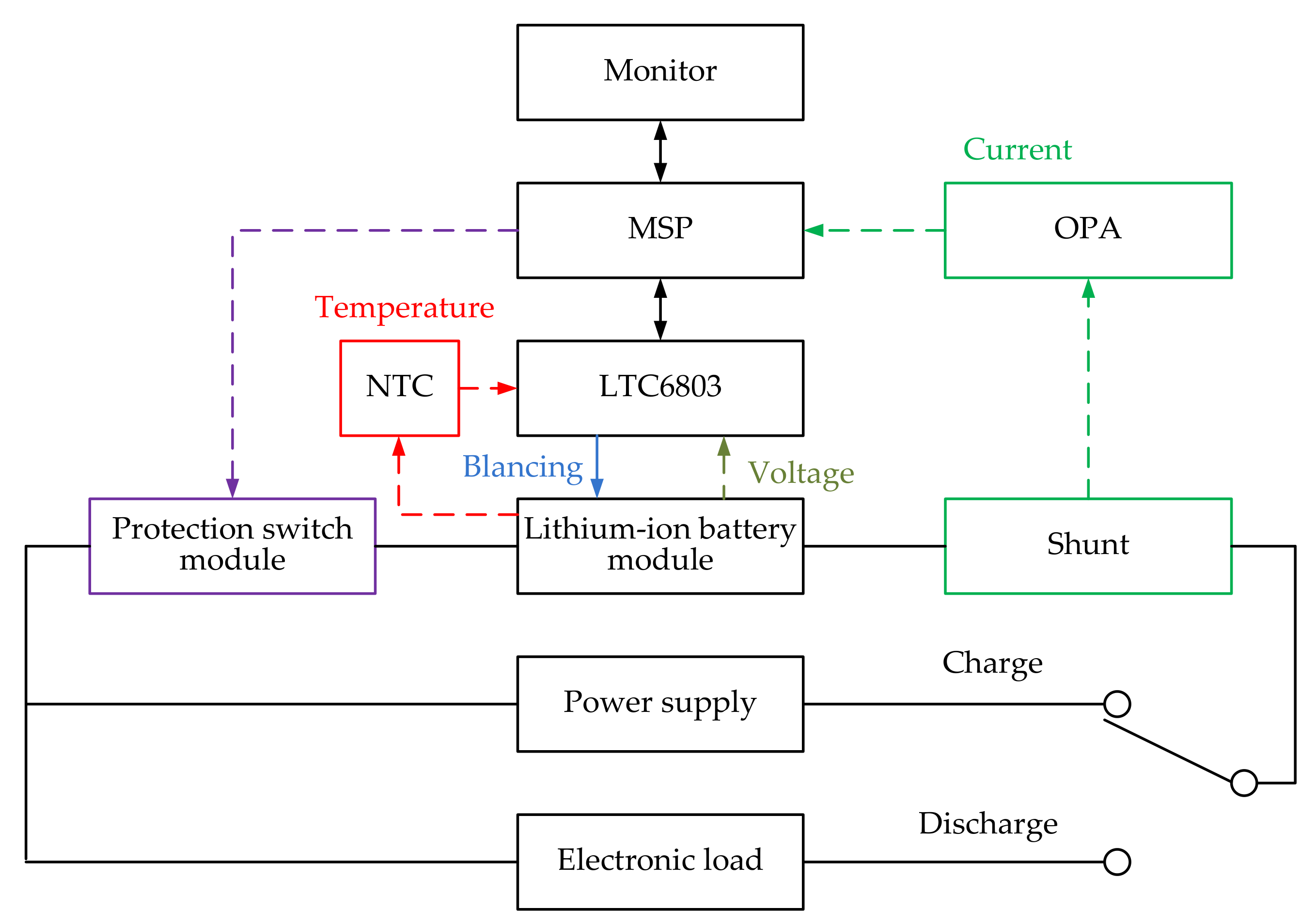
The system structure of the modular battery management system proposed in this paper is composed of a monitor, lithium-ion battery module, and battery management system. The battery management system of the electric vehicles is mainly composed of a mixed-signal processor, voltage measurement module, current measurement module, temperature measurement module, battery balancing module, and protection switch module. The system structure is shown in
Figure 1.
2.1. Lithium-Ion Battery Module
In this research, the tested battery module of the modular battery management system is using Samsung battery, the rated voltage of the unit battery is 3.65 V, the rated capacity is 2900 mAh, and 48 18650 lithium-ion batteries are used to form the battery module in 12 series and 4 parallel modes. The appearance of the battery module is shown in
Figure 2.
2.2. Modular Battery Management System
2.2.1. Mixed-Signal Processor (MSP)
The mixed-signal processor of this system is mainly composed of the mixed-signal processor (MSP) and control circuit. In addition to displaying the received battery module data on the monitor, the main function of the MSP is to collect the data of voltage measurement module, current measurement module, and temperature measurement module. These collected data are then analyzed to determine whether the system needs to start the battery balancing power circuit and judge whether the battery module has overcharge, over-discharge, or over-temperature. Under this abnormal operation situation, the protection switch is started to carry out the system protection mechanism.
2.2.2. Voltage Measurement Module
In order to accurately and quickly measure the voltage data of lithium-ion batteries, the voltage measurement module mainly uses the measurement chip LTC6803. This research designs a fast sampling rate and accurate module with high common-mode voltage and anti-noise ability. The voltage of the cell module can be measured every 13 ms and transmitted to the mixed-signal processor.
2.2.3. Current Measurement Module
The current measurement module mainly uses the shunt component. This research designs a precise and fast current measurement module to transmit the measured current signal to the mixed-signal processor in the process of battery charging and discharging.
2.2.4. Temperature Measurement Module
The temperature measurement module is composed of a measuring chip LTC6803 and a thermistor, which transmits the measured temperature to the mixed-signal processor through the partial voltage signal on the thermistor. The resistance value of the thermistor decreases with the increase in temperature. Thus, the temperature of the thermistor is calculated using Formula (1).
where
T is the temperature with the unit K,
R is the resistance value after temperature change,
B is the change parameter of the thermistor, its value is fixed at 3892,
R0 is the resistance at
T0 (25 °C = 298.15 K). Formula (2) can be obtained by conversion
In formula (2), .
2.2.5. Battery Balancing Module
The battery balancing module is controlled by the mixed-signal processor to determine whether to start the battery balancing module. During the charging process, the mixed-signal processor will quickly detect the battery voltage of each cell on the module. If the voltage difference between the battery with the highest voltage and the battery with the lowest voltage is too large, the mixed-signal processor will send a command to the battery balancing module to activate the automatic battery balancing function. This action can prevent the battery voltage difference between each cell is too large.
2.2.6. Protection Switch Module
The protection switch module is mainly composed of MOSFET. The selected MOSFET is IRF540. When the controller judges that the protection needs to be started, it will send out the signal source and cut off the voltage of the gate and source on the MOSFET, making the switch closed and the battery out of working state. The protection switch module is designed to protect the battery module from overcharge, over-discharge, or over-temperature. It can be controlled by a mixed-signal processor to determine whether to start the protection action according to the voltage, current, and temperature of the battery module.
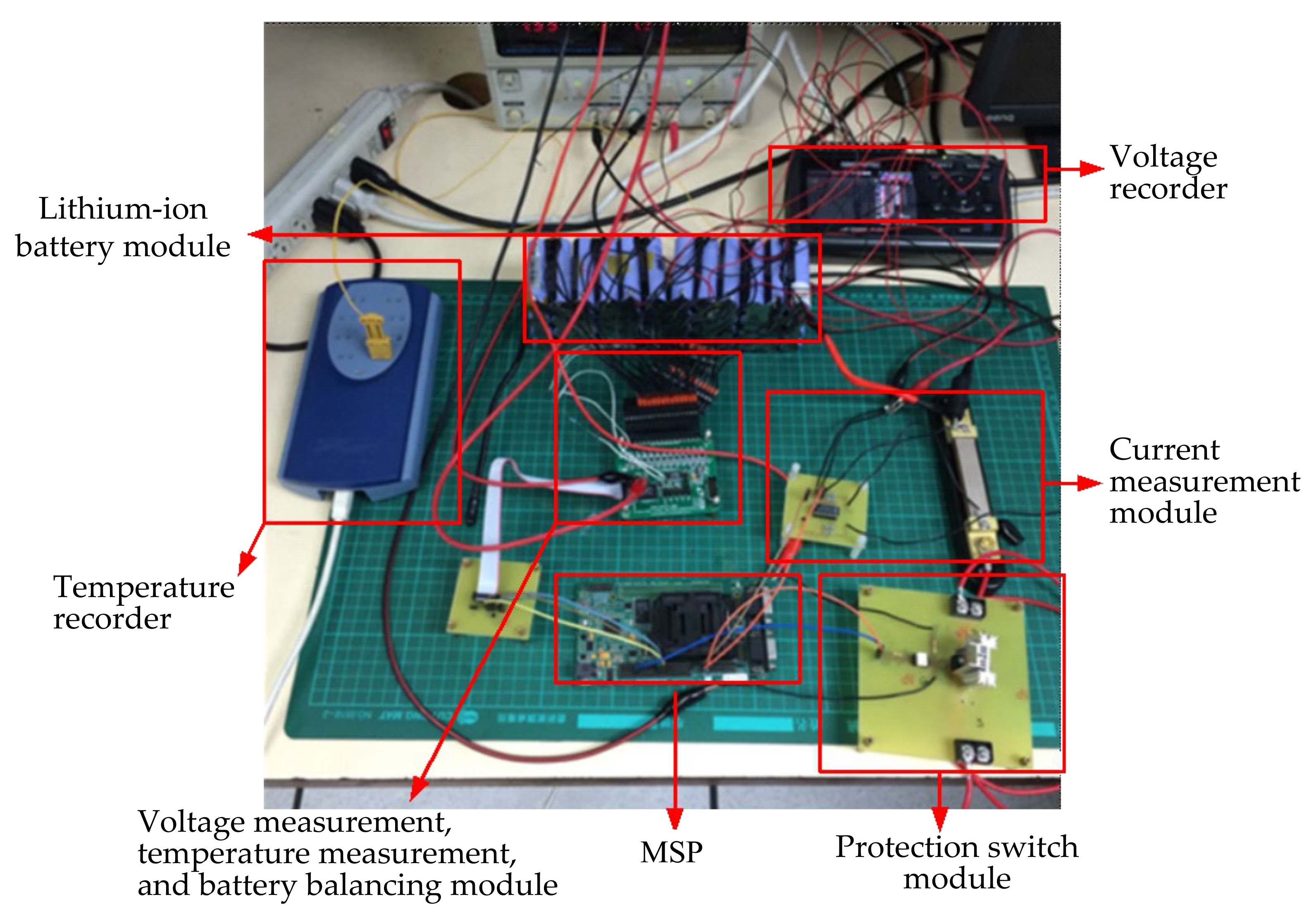
The overall test platform of lithium-ion battery module management system is shown in
Figure 3.
3. Operation Process of the Battery Management System
Since the voltage of each cell in the battery module could be different, the performance of the battery module is determined by the single battery with the worst performance in the whole battery module. After a long time of charging and discharging, the voltage difference of each battery in the battery module will be larger and larger. When the voltage difference is too large, the voltage of a single battery will be fully charged before the others. Under this overcharging condition, the system will enter the protection state earlier. When discharging, the battery with the lowest voltage will let the management system judge that the battery module has been over-discharged and also enter the protection state earlier. These two situations mentioned above will reduce the service time of the whole battery module. In this way, the long-term cycle will make the voltage difference between every single battery larger and larger, resulting in shorter battery module use time and more likely to cause battery module damage.
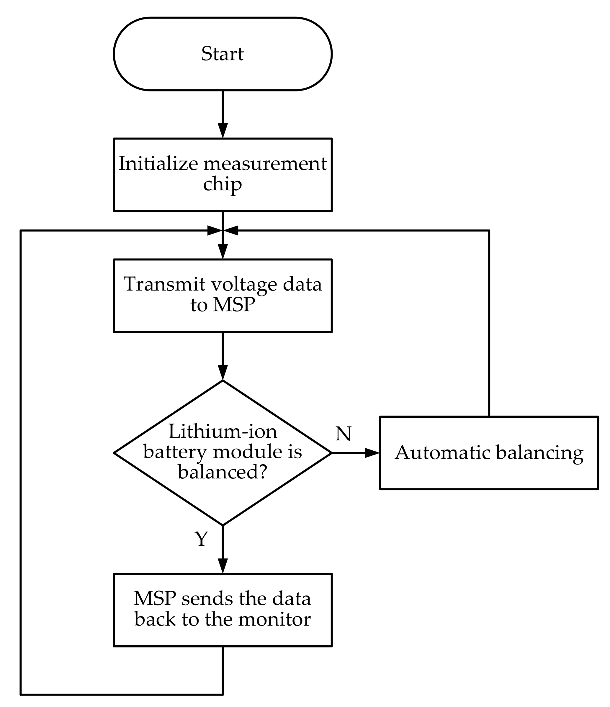
In order to avoid the excessive voltage difference between the cells during the charging and discharging process of the lithium-ion battery module, the battery balancing module of the system has the function of automatic balance. The voltage and temperature data are returned to the mixed-signal processor by measuring the chip, and the voltage of each battery is detected by the hybrid signal processor. When the voltage difference between the battery with the highest voltage and the battery with the lowest voltage is too large, the hybrid signal processor will send a command to the measurement chip to start the automatic balance function to maintain the single voltage difference of lithium-ion battery module not to be too large. It would reduce the risk of battery damage and maintain the battery life. The system will continuously monitor the battery module to achieve cell battery balancing. The flow chart of the automatic battery balancing is shown in
Figure 4.
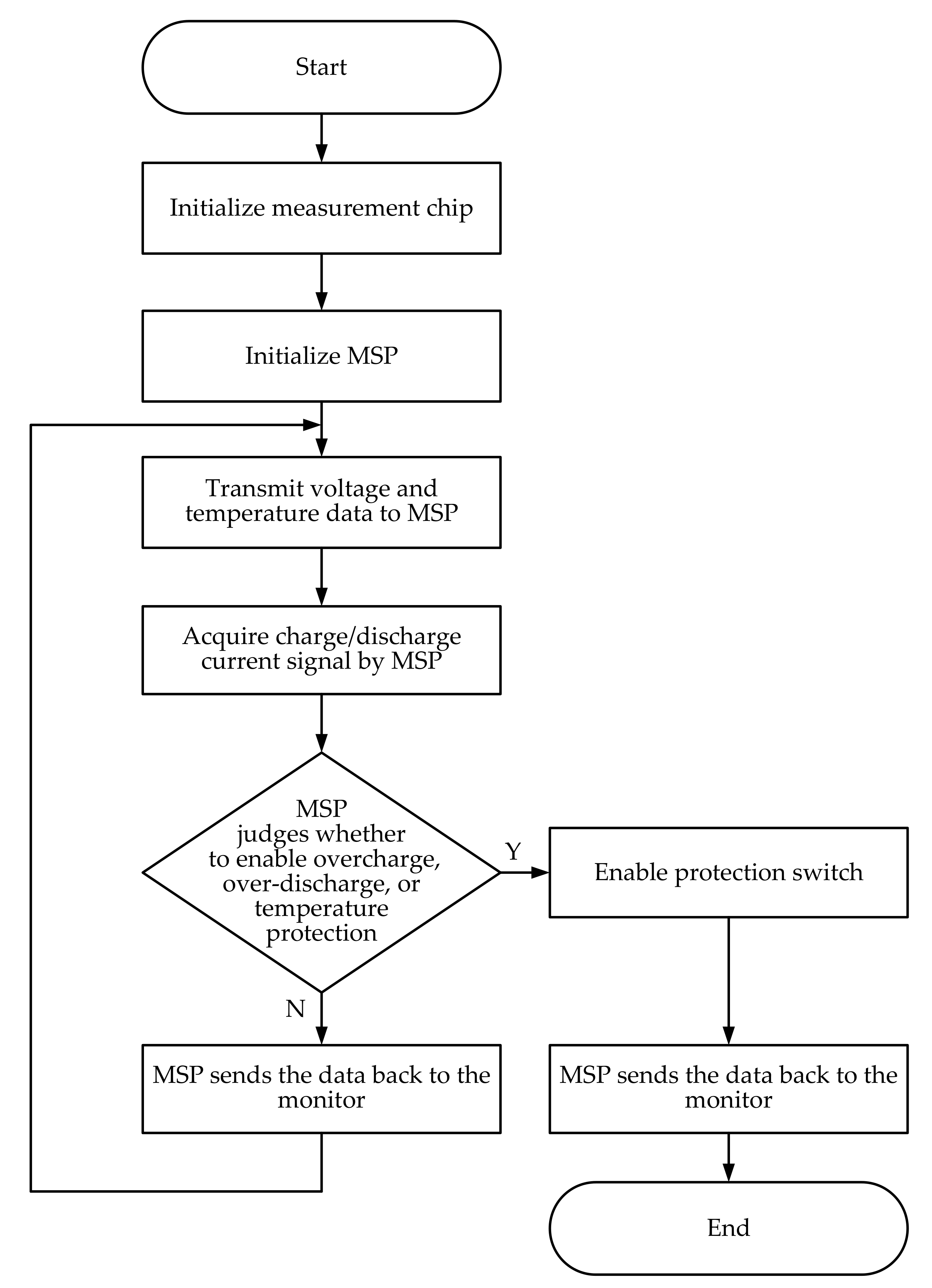
The main operation process of this system is briefly described as follows. Firstly, when monitoring and managing the battery module, the voltage measurement module, current measurement module, temperature measurement module, and the ADC functions of mixed-signal processor are all started. Both the voltage and temperature data are returned to the mixed-signal processor by various measuring chips. At this time, the mixed-signal processor synchronously captures the charging or discharging current value signal. The mixed-signal processor detects if the battery voltage is lower than 2.8 V or higher than 4.3 V, and whether the battery temperature is higher than 60 °C. The protection switch module will be started when one of these conditions occurrs. Finally, the battery management system will display the measurement results on the monitor and continuously manage the battery module. The overall flow chart of the system operation is shown in
Figure 5.
4. System Function Validation and Discussion
In order to validate the measurement accuracy of the battery management system, the measured voltage, current, and temperature of battery module are compared with voltage recorder, voltmeter, and temperature recorder, respectively.
4.1. Voltage Measurement
In this paper, the voltage measurement is divided into three parts. The first part is the comparison of voltage measurement errors. After the battery has been standing for a period of time, the measurement chip, voltmeter, and voltage recorder are used to measure the voltage, respectively. The results measured by the measurement chip will be transmitted to the computer for storage through the mixed-signal processor. The measurement results are compared in
Table 1. The error of the voltage recorder 0.195% is smaller than the error of the voltmeter 0.227%. The voltage recorder is chosen as the comparison benchmark in the subsequent measurement.
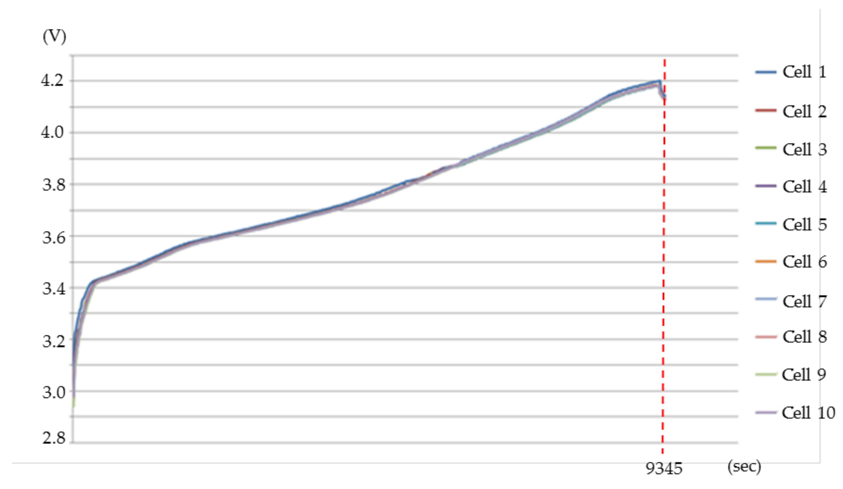
The second part is the charging voltage measurement. After the battery module is discharged to a single battery voltage of 2.8 V, the battery module will stop discharging immediately and stand still for a period of time, and then charge with a constant current of 4.5 A. When a single battery in the battery module is charged to about 4.2 V, it is deemed that the battery module has been fully charged. At the same time, the action of the automatic balancing circuit is observed by the charging process. During the charging process, each cell voltage of the battery module is measured by the measuring chip and the voltage recorder separately. The error comparisons of initial charge voltage and final charge voltage of each cell are shown in
Table 2.
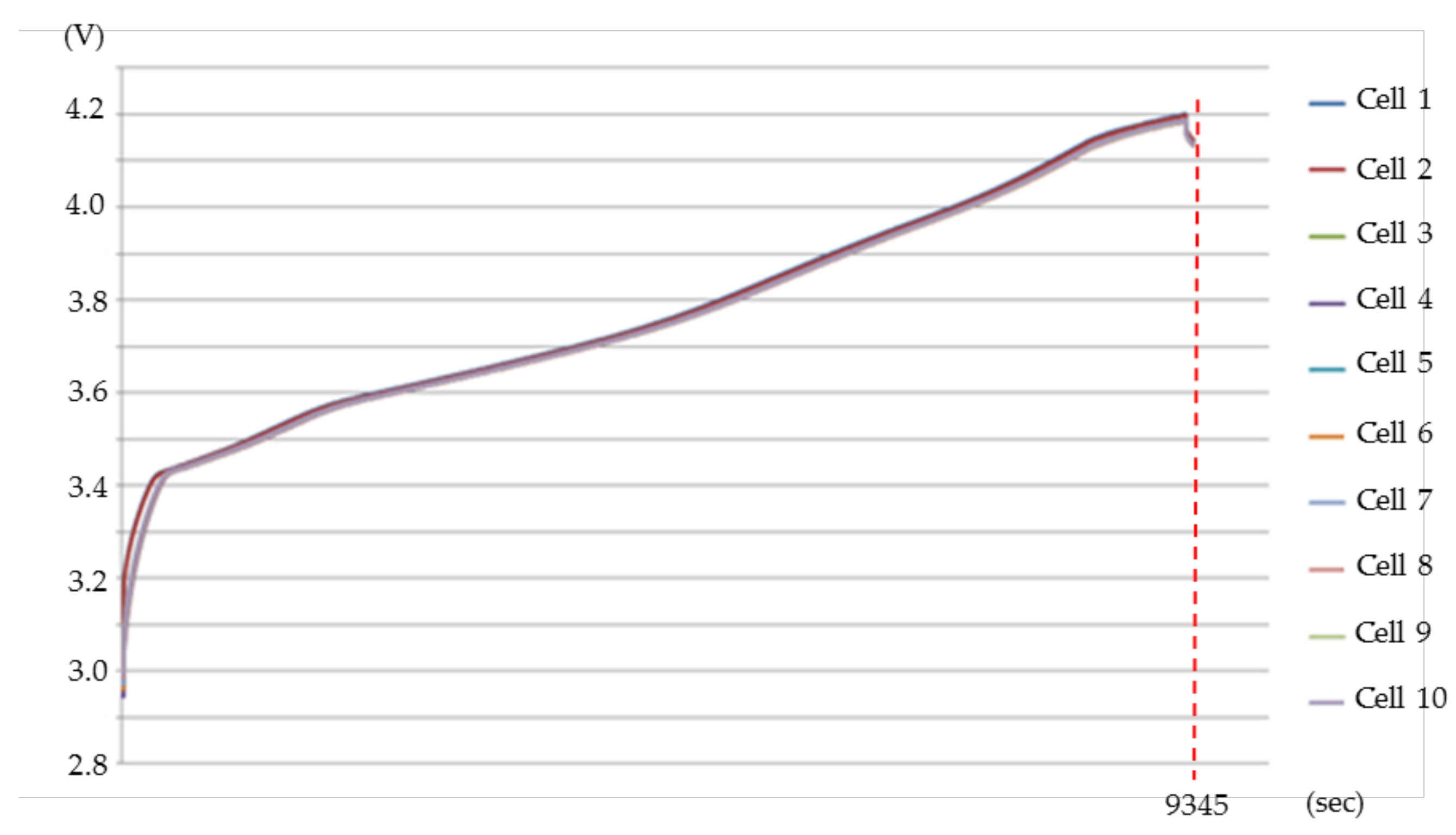
Figure 6 and
Figure 7 show the charging curves measured by the measurement chip and the voltage recorder. As the recorder has only ten measuring channels, only the first 10 batteries are taken as the comparison object in the charging and discharging measurement. The total charging time is 9345 s. The average errors of the initial and final charging voltage are 0.715% and 0.131%, respectively. The maximum cell voltage difference is only 0.015 V. It can be obviously found in the locally enlarged diagram of
Figure 8. There is an automatic balancing action during the charging process. When the charging time reaches 805 s, the cell charging voltages have almost been balanced.
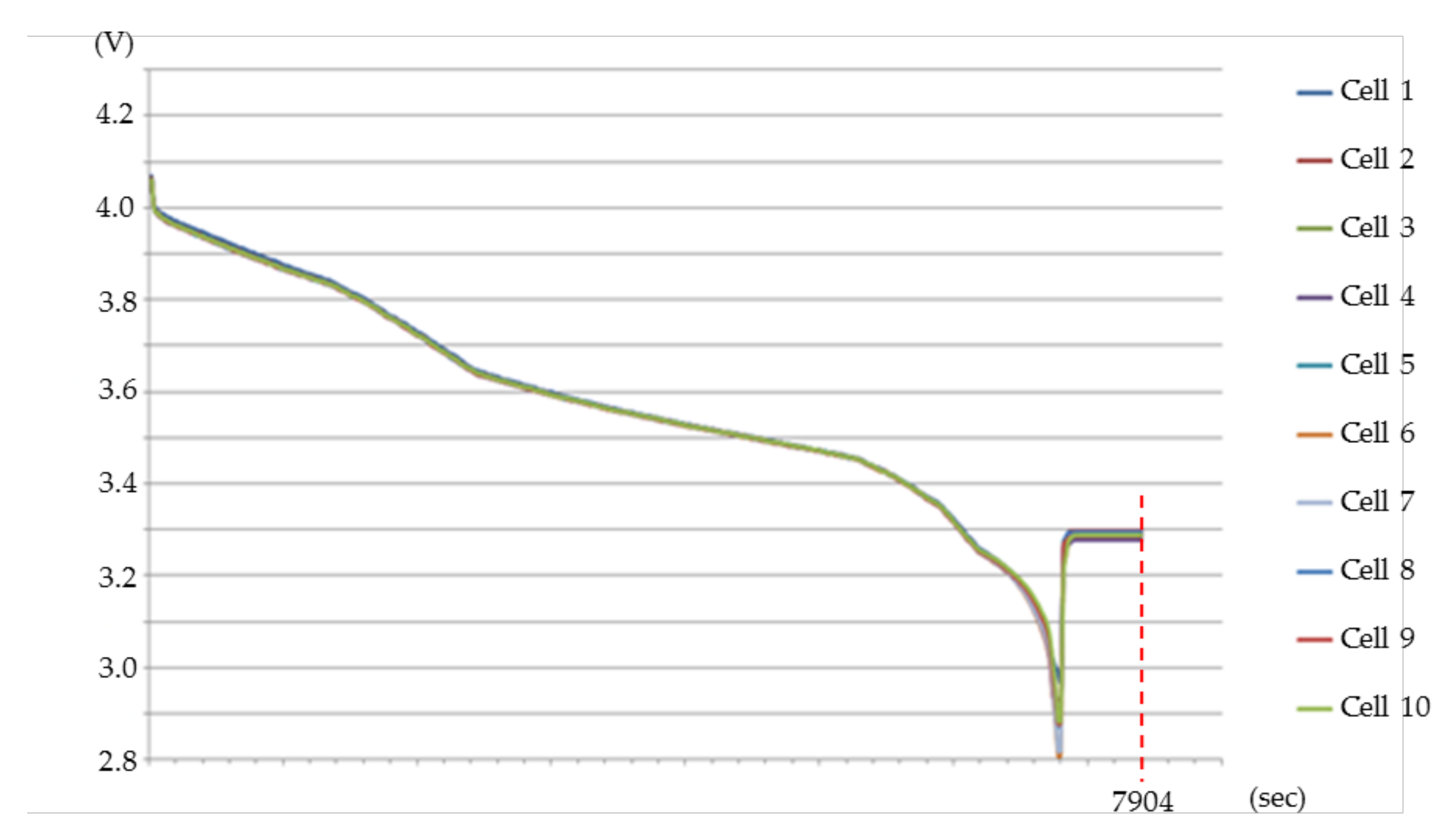
The third part is the discharge voltage measurement. After the second part is completed, the battery module will be set aside for a period of time and then discharged at a constant current of 4.5 A. When the voltage of a single battery in the battery module is about 2.8 V, it is considered that the battery module has been fully discharged. The action of the automatic balancing circuit is observed throughout the discharge process. During the discharge process, each cell voltage is measured by both the measuring chip and voltage recorder. The error comparisons of initial discharge voltage and final discharge voltage of each cell are shown in
Table 3.
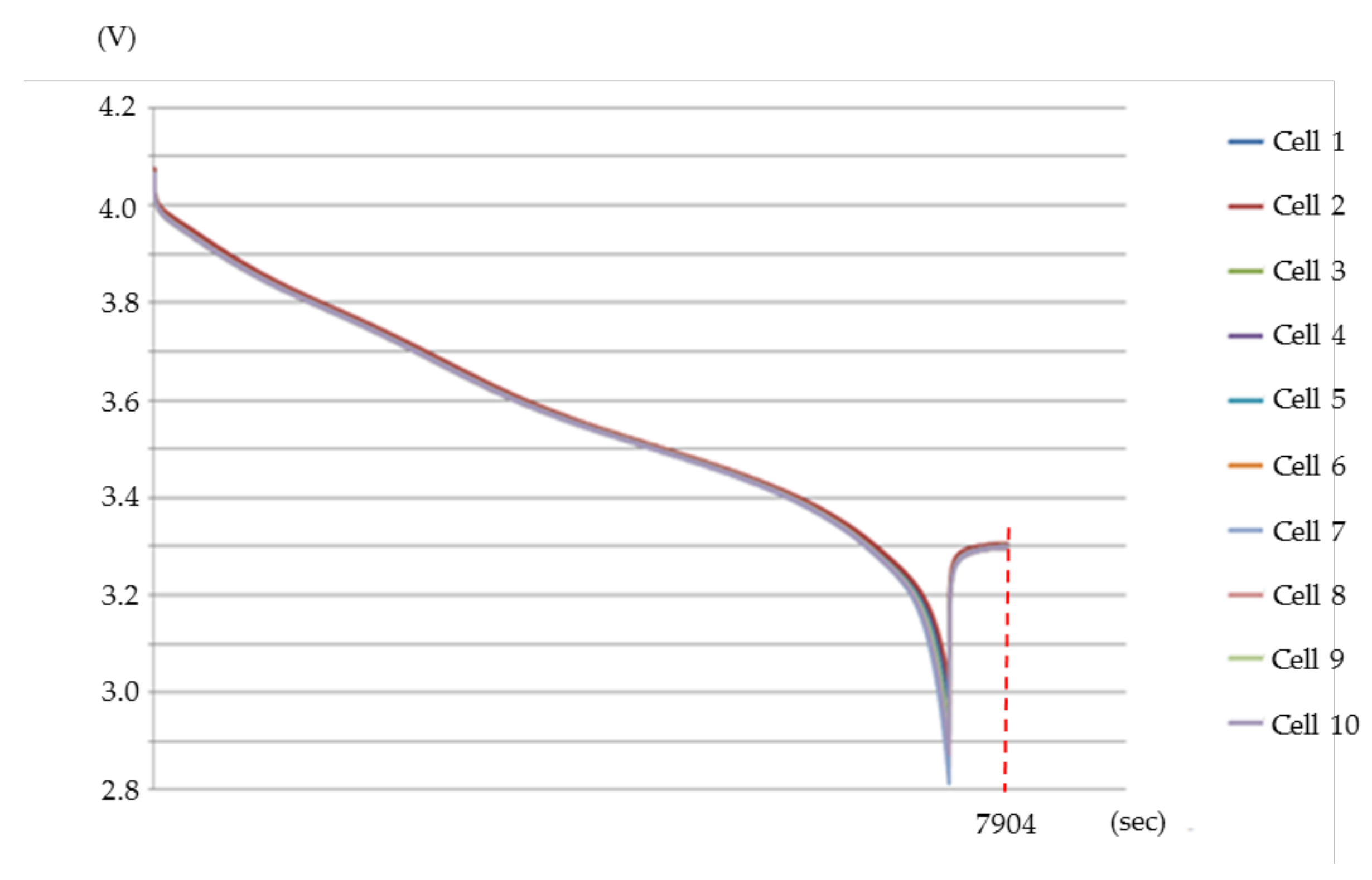
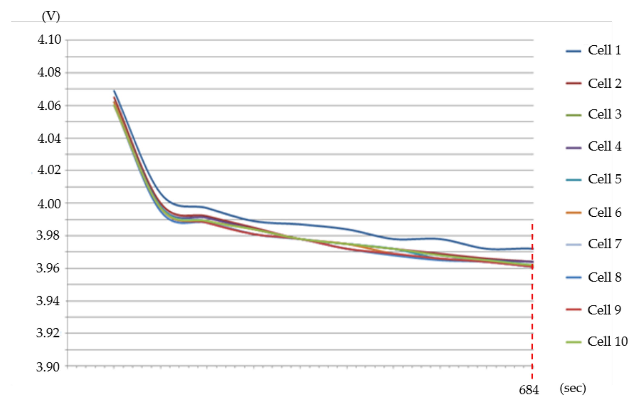
Figure 9 and
Figure 10 present the discharge curves measured by the measurement chip and the voltage recorder. The total discharging time is 7904 s. The average error of the initial and final voltage of the discharge is 0.099% and 0.341%, respectively. The maximum cell voltage difference is only 0.011 V. It can be obviously found in the locally enlarged diagram of
Figure 11. There is an automatic balancing action during the discharging process. When the discharging time reaches 684 s, the cell charging voltages have almost been balanced.
4.2. Current Measurement
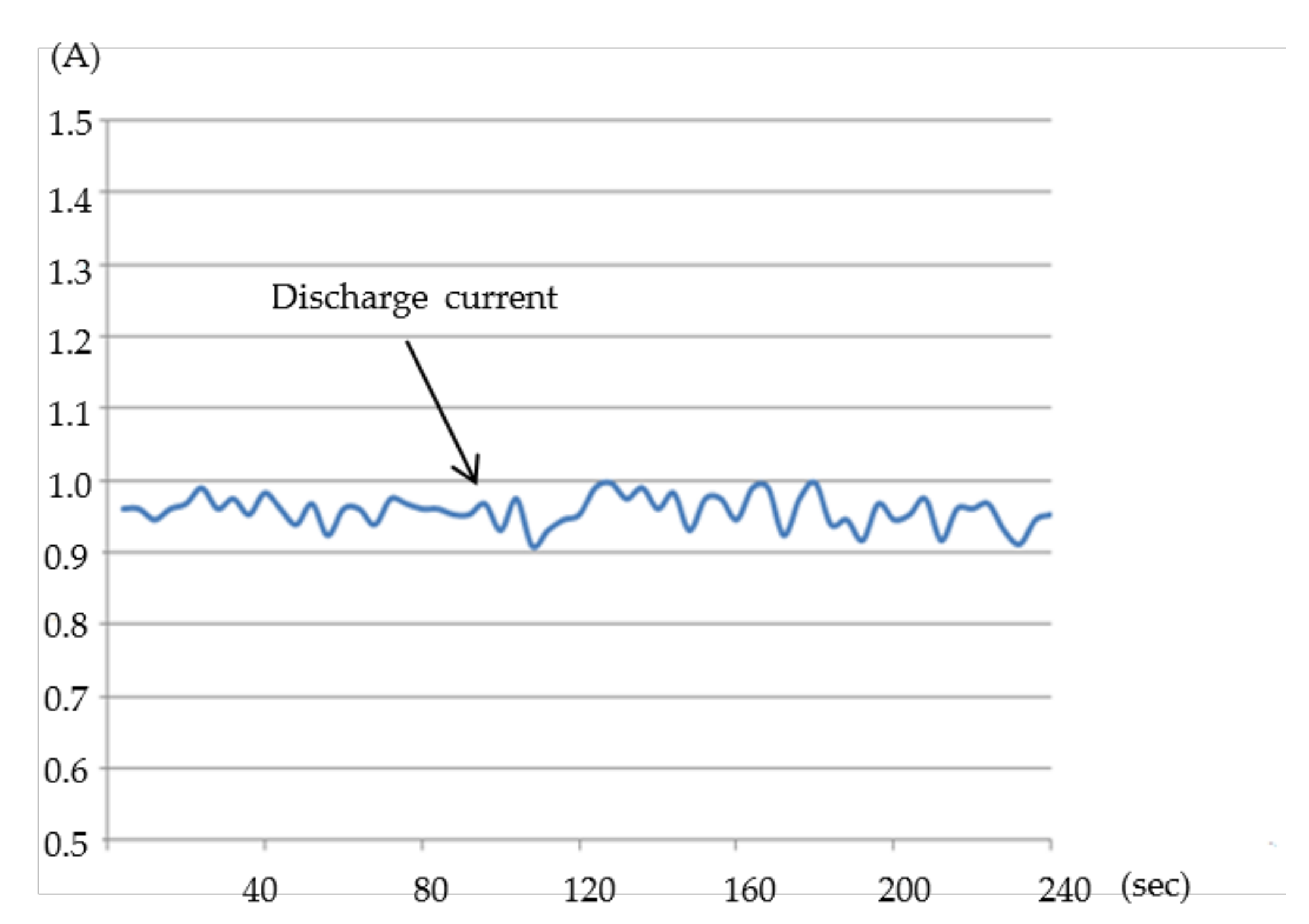
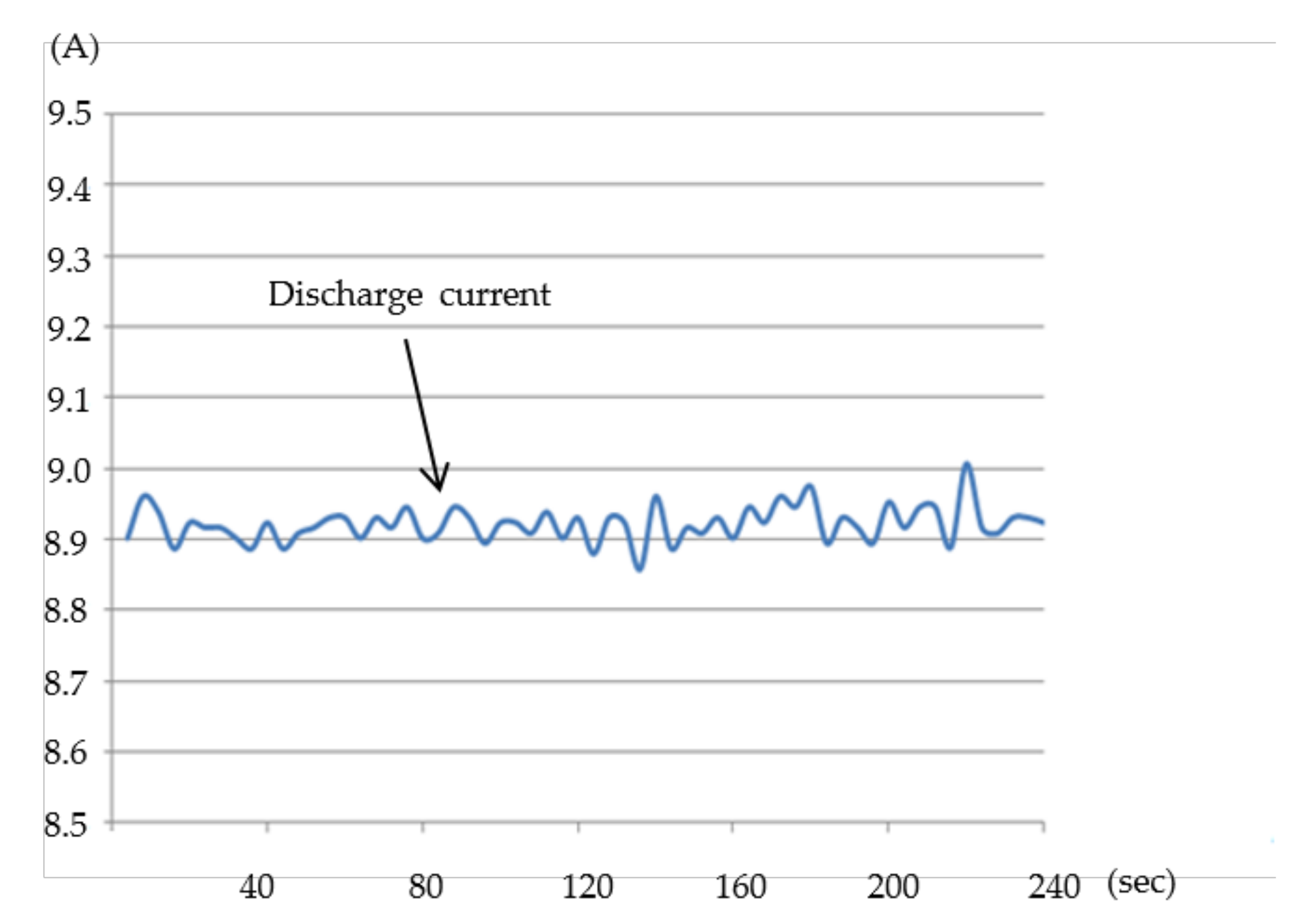
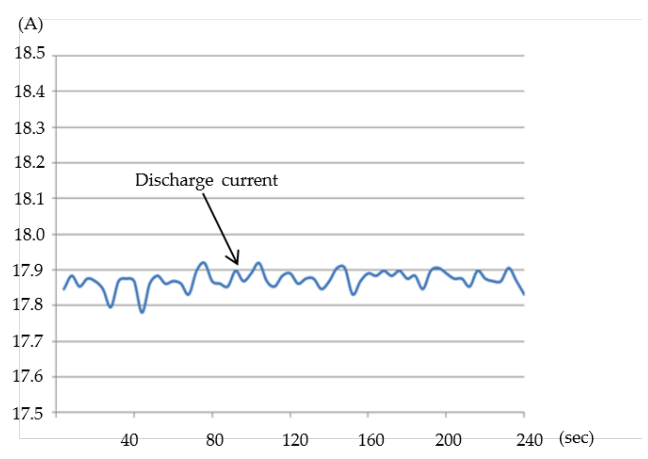
The maximum discharge current of the battery in this system is 18 A. Since the current of the electric vehicle will change with different driving conditions, the current measurement is used to validate whether the current measurement function of the system can normally measure under different current values. In this paper, the electronic load is applied to discharge the lithium-ion battery.
Figure 12,
Figure 13 and
Figure 14 show the measurement of different discharge current values, which are 1 A, 9 A, and 18 A. It can be found from the measurement results that although there are some errors, the error range is about 0.1 A. It has a certain accuracy in current measurement. Compared with the actual current value, the error is small, which is suitable for current measurement in the battery management system.
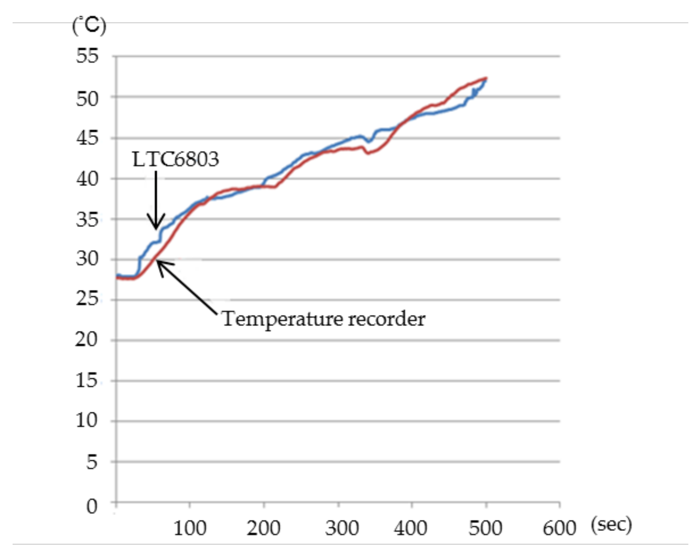
4.3. Temperature Measurement
The validation method of the temperature measurement of the system is to change the ambient temperature manually and compare the measured temperature of the temperature recorder with the value measured by the measurement chip. The temperature is recorded once per second. The temperature curves measured by the measurement chip and the temperature recorder are shown in
Figure 15. It can be seen from the figure that the difference between the temperature monitored by the system and the actual measured temperature is small. It is proved that the system can effectively monitor the temperature change and achieve the basis of monitoring the temperature and judging whether to start the temperature protection.
4.4. System Function Verification
To validate that the lithium-ion battery management system designed in this paper can effectively manage the lithium-ion battery module, the overcharge, over-discharge, and over-temperature protection mechanism, as well as the single cell voltage balancing function, are tested. The purpose of the overcharge protection testing is to validate whether the overcharge protection function is normal. When the single voltage of a lithium-ion battery reaches the set maximum limit, the mixed-signal processor sends a signal to cut off the switch to make the lithium-ion battery out of the charging state. The battery voltage, charge current, and temperature of the lithium-ion battery module are shown in
Figure 16.
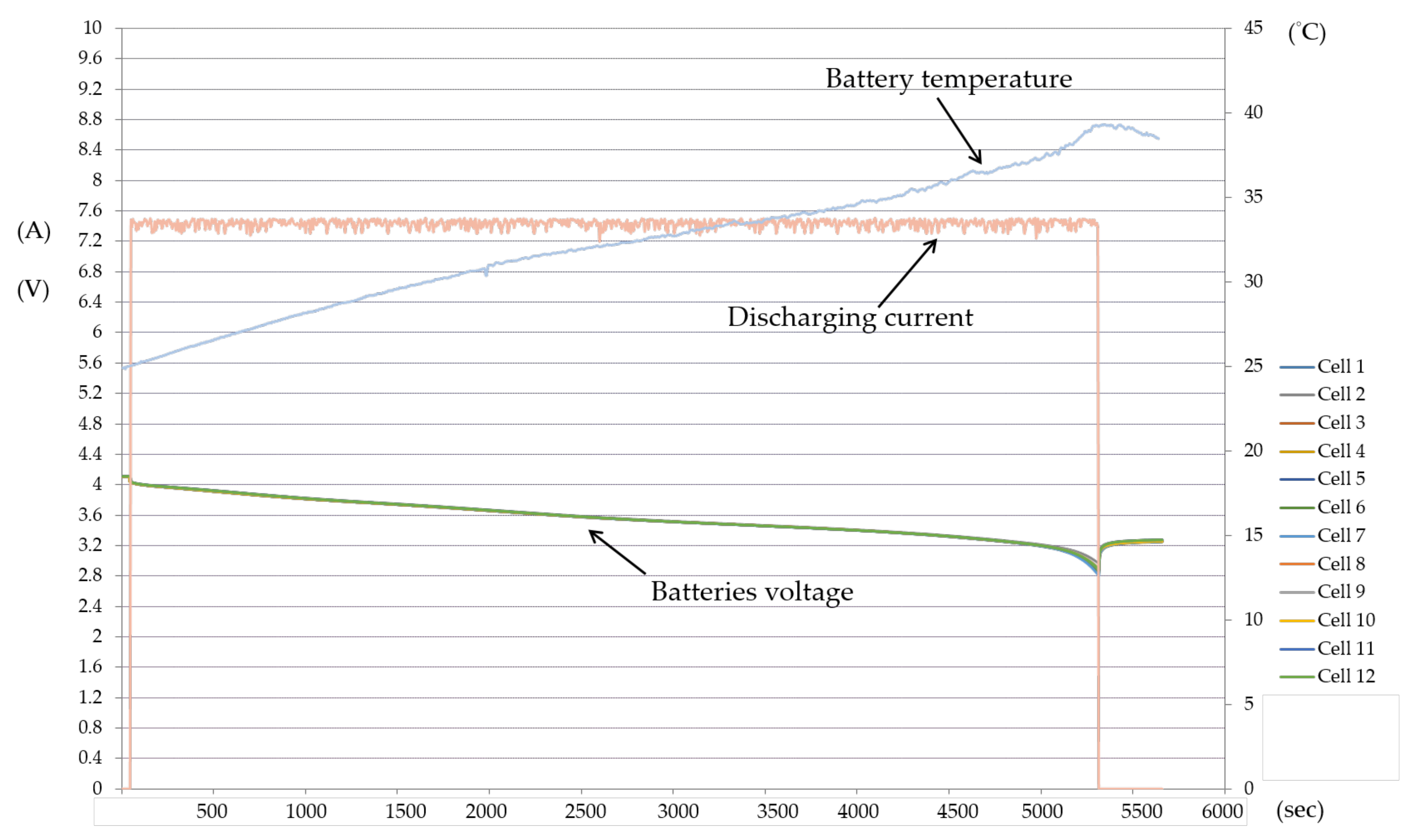
The purpose of the over-discharge protection testing is to validate whether the over-discharge protection function is normal. When the voltage of a single lithium-ion battery reaches the set minimum lower limit, the mixed-signal processor sends a signal to cut off the switch to make the lithium-ion battery out of the discharge state. The battery voltage, discharge current, and temperature of the lithium-ion battery module are shown in
Figure 17.
The purpose of the temperature protection testing is to validate whether the temperature protection function is normal. In the case of not deliberately damaging the battery, the temperature of the battery will rarely exceed its safe range. Therefore, the temperature will be changed artificially for testing this function. This testing will be carried out under the condition of battery discharge. When the temperature reaches 60 °C, the mixed-signal processor will send a signal to cut off the switch to make the lithium-ion battery out of the high temperature state. The battery voltage, discharge current, and temperature of the lithium-ion battery module are shown in
Figure 18. The sampling frequency of the above testing is once per 5 s.
5. Conclusions
In this paper, a modular battery management system is proposed for an electric motorcycle. In addition to a battery management system, this system can also be used in the related research on lithium-ion batteries. In the process of measurement, the measured data can be stored for future data analysis. Besides, this system can also be used for other battery measurements besides lithium-ion batteries. The measurement module has an independent subsystem, so it can operate multiple sets of modules through one master controller at the same time, which can achieve the function of managing multiple battery systems by one master controller. Moreover, the system structure can significantly reduce the cost of the whole system and improve efficiency. The testing results show that the proposed modular battery management system has the functions of battery balance management, overcharge and discharge control, temperature protection control. The system is cheap and safe to use in battery management of electric vehicles.
Although the design of the modular battery management system proposed in this paper has the basic ability to be applied to the electric motorcycle, the capacity calculation and estimation have not been added to the charging and discharging system in this study. At present, the discharging current is constant, but the actual load condition of the electric motorcycle changes dramatically when it is used. In the future, a capacity estimation mechanism should be added, which can be used not only to calculate the battery efficiency but also to estimate the remaining capacity of the battery and to inform the users of the power shortage in advance.
Author Contributions
Conceptualization, H.-C.C. and S.-L.W.; data curation, H.-C.C., S.-L.W. and S.-S.L.; validation, H.-C.C., S.-L.W., S.-S.L. and C.-Y.L. All authors have read and agreed to the published version of the manuscript.
Funding
This research received no external funding.
Institutional Review Board Statement
Not applicable.
Informed Consent Statement
Not applicable.
Data Availability Statement
The study did not report any data.
Conflicts of Interest
The authors declare no conflict of interest.
References
- Hossein Ranjbar, A.; Banaei, A.; Khoobroo, A.; Fahimi, B. Online Estimation of State of Charge in Li-Ion Batteries Using Impulse Response Concept. IEEE Trans. Smart Grid 2012, 3, 360–367. [Google Scholar] [CrossRef]
- Hannan, M.A.; Hoque, M.M.; Hussain, A.; Yusof, Y.; Ker, P.J. State-of-the-Art and Energy Management System of Lithium-Ion Batteries in Electric Vehicle Applications: Issues and Recommendations. IEEE Access 2018, 6, 19362–19378. [Google Scholar] [CrossRef]
- Rahmani, F.; Niknejad, P.; Agarwal, T.; Barzegaran, M. Gallium Nitride Inverter Design with Compatible Snubber Circuits for Implementing Wireless Charging of Electric Vehicle Batteries. Machines 2020, 8, 56. [Google Scholar] [CrossRef]
- Chern, T.L.; Pan, P.L. The Research of Smart Li-ion Battery Management System. In Proceedings of the Second IEEE Conference on Industrial Electronics and Applications, Harbin, China, 23–25 May 2007; pp. 2273–2277. [Google Scholar] [CrossRef]
- Juzlow, M.W.; Mayer, S.T. Design Considerations for Lithium-ion Cells Art l. Cell Components. In Proceedings of the 12th Annual Battery Conf. on Applications and Advances, Long Beach, CA, USA, 14–17 January 1997; pp. 181–188. [Google Scholar]
- Xu, D.; Wang, L.; Yang, J. Research on Li-ion Battery Management System. In Proceedings of the 2010 International Conf. on Electrical and Control Engineering, Wuhan, China, 25–27 June 2010; pp. 4106–4109. [Google Scholar] [CrossRef]
- Zheng, M.X.; Qi, B.J.; Wu, H.J. A Li-ion Battery Management System Based on CAN-bus for Electric Vehicle. In Proceedings of the 2008 3rd IEEE Conf. on Industrial Electronics and Applications, Singapore, Singapore, 3–5 June 2008; pp. 1180–1184. [Google Scholar] [CrossRef]
- Motapon, S.N.; Lupien-Bedard, A.; Dessaint, L.; Fortin-Blanchette, H.; Al-Haddad, K. A Generic Electrothermal Li-ion Battery Model for Rapid Evaluation of Cell Temperature Temporal Evolution. IEEE Trans. Ind. Electron. 2017, 64, 998–1008. [Google Scholar] [CrossRef]
- Chen, X.; Shen, W.; Dai, M.; Cao, Z.; Jin, J.; Kapoor, A. Robust Adaptive Sliding-Mode Observer Using RBF Neural Network for Lithium-Ion Battery State of Charge Estimation in Electric Vehicles. IEEE Trans. Veh. Technol. 2016, 65, 1936–1947. [Google Scholar] [CrossRef]
- Zhu, F.; Liu, G.; Tao, C.; Wang, K.; Jiang, K. Battery Management System for Li-Ion Battery. J. Eng. 2017, 2017, 1437–1440. [Google Scholar] [CrossRef]
- Chen, C.; Jin, J.; He, L. A New Battery Management System for Li-ion Battery Packs. In Proceedings of the 2008 IEEE Asia Pacific Conf. on Circuits and Systems, Macao, China, 30 November–3 December 2008. [Google Scholar] [CrossRef]
- Lin, X.; Perez, H.E.; Siegel, J.B.; Stefanopoulou, A.G. Online Parameterization of Lumped Thermal Dynamics in Cylindrical Lithium Ion Batteries for Core Temperature Estimation and Health Monitoring. IEEE Trans. Control Syst. Technol. 2013, 21, 1745–1755. [Google Scholar] [CrossRef]
- Hsieh, Y.C.; Huang, C.S. Li-ion Battery Charger Based on Digitally Controlled Phase-shifted Full-bridge Converter. IET Power Electron. 2011, 4, 242–247. [Google Scholar] [CrossRef]
- Zhang, H.; Wang, Y.; Qi, H.; Zhang, J. Active Battery Equalization Method Based on Redundant Battery for Electric Vehicles. IEEE Trans. Veh. Technol. 2019, 68, 7531–7543. [Google Scholar] [CrossRef]
- Gong, X.; Xiong, R.; Mi, C.C. Study of the Characteristics of Battery Packs in Electric Vehicles with Parallel-Connected Lithium-Ion Battery Cells. IEEE Trans. Ind. Appl. 2015, 51, 1872–1879. [Google Scholar] [CrossRef]
- Zhang, R.; Wu, J.; Wang, R.; Yan, R.; Zhu, Y.; He, X. A Novel Battery Management System structure Based on an Isolated Power/Data Multiplexing Transmission Bus. IEEE Trans. Ind. Electron. 2019, 66, 5979–5991. [Google Scholar] [CrossRef]
- Khalid, H.M.; Ahmed, Q.; Peng, J.C.-H. Health Monitoring of Li-Ion Battery Systems: A Median Expectation Diagnosis Approach (MEDA). IEEE Trans. Transp. Electrif. 2015, 1, 94–105. [Google Scholar] [CrossRef]
- Rahmani, F. Electric Vehicle Charger based on DC/DC Converter Topology. Int. J. Eng. Sci. Comput. 2018, 6, 18879–18883. [Google Scholar]
- Zaitsev, A.; Butarovich, D.; Smirnov, A. Basic Principles of Automotive Modular Battery Management System Design. IOP Conf. Ser. Mater. Sci. Eng. 2020, 819. [Google Scholar] [CrossRef]
- Bui, T.M.N.; Niri, M.F.; Worwood, D.; Dinh, T.Q.; Marco, J. An Advanced Hardware-in-the-loop Battery Simulation Platform for the Experimental Testing of Battery Management System. Proceedings of 2019 23rd International Conference on Mechatronics Technology (ICMT), Salerno, Italy, 23–26 October 2019. [Google Scholar] [CrossRef]
- Sathyamoorthi, G.R.; Mubanda, T.S. Design and Implementation of a Scalable Battery Management System; Chalmers Tekniska Högskola: Göteborg, Sweden, 2020. [Google Scholar]
- Chen, S.J.; Zheng, M.X.; Mam, Q.F. Design of Battery Management System Based on STM32 and LTC6803. Chin. J. Power Sources 2015, 39, 280–282. [Google Scholar]
- Zhu, W. The Cell Battery Management Module Based on LTC6802 for EV Applications. Mach. Electron. 2012, 2012, 33–36. [Google Scholar]
- Chang, S.C.; Liu, C.Y. Study of Series Li-ion Batteries Electric Energy Diagnosis and Management System. J. Sci. Eng. Technol. 2011, 7, 69–80. [Google Scholar]
- Xin, Z.; Ge, Y.; Bo, W.; Zhang, Y.; Li, Y.; Yang, J. Design of Microcontroller-Based Battery Management System for Pure Electric Vehicle. Trans. Chin. Soc. Agric. Eng. 2014, 30, 163–170. [Google Scholar]
- Khalid, H.M.; Peng, J.C.-H. Bidirectional Charging in V2G Systems: An In-Cell Variation Analysis of Vehicle Batteries. IEEE Syst. J. 2020, 14, 3665–3675. [Google Scholar] [CrossRef]
- Ghaeminezhad, N.; Ouyag, Q.; Hu, X.; Wang, Z. Active Cell Equalization Topologies Analysis for Battery Packs: A Systematic Review. IEEE Trans. Power Electron. 2021, 36, 9119–9135. [Google Scholar] [CrossRef]
- Carkhuff, B.G.; Demirev, P.A.; Srinivasan, R. Impedance-Based Battery Management System for Safety Monitoring of Lithium-Ion Batteries. IEEE Trans. Ind. Electron. 2018, 65, 6497–6504. [Google Scholar] [CrossRef]
Figure 1.
The system structure of the modular battery management system.
Figure 1.
The system structure of the modular battery management system.
Figure 2.
Lithium-ion battery module.
Figure 2.
Lithium-ion battery module.
Figure 3.
The overall test platform of Lithium-ion battery module management system.
Figure 3.
The overall test platform of Lithium-ion battery module management system.
Figure 4.
Flow chart of the battery balancing.
Figure 4.
Flow chart of the battery balancing.
Figure 5.
Overall flow chart of the management system operation.
Figure 5.
Overall flow chart of the management system operation.
Figure 6.
Charging curve measured by LTC6803.
Figure 6.
Charging curve measured by LTC6803.
Figure 7.
Charging curve measured by voltage recorder.
Figure 7.
Charging curve measured by voltage recorder.
Figure 8.
Charging curve measured by LTC6803.
Figure 8.
Charging curve measured by LTC6803.
Figure 9.
Discharge curve measured by LTC6803.
Figure 9.
Discharge curve measured by LTC6803.
Figure 10.
Discharge curve measured by voltage recorder.
Figure 10.
Discharge curve measured by voltage recorder.
Figure 11.
Partial enlargement of the discharge curve measured by LTC6803.
Figure 11.
Partial enlargement of the discharge curve measured by LTC6803.
Figure 12.
Discharge current value 1 A.
Figure 12.
Discharge current value 1 A.
Figure 13.
Discharge current value 9 A.
Figure 13.
Discharge current value 9 A.
Figure 14.
Discharge current value 18 A.
Figure 14.
Discharge current value 18 A.
Figure 15.
Temperature measurement curves of LTC6803 and temperature recorder.
Figure 15.
Temperature measurement curves of LTC6803 and temperature recorder.
Figure 16.
Overcharge protection of the lithium-ion battery module.
Figure 16.
Overcharge protection of the lithium-ion battery module.
Figure 17.
Over-discharge protection of the lithium-ion battery module.
Figure 17.
Over-discharge protection of the lithium-ion battery module.
Figure 18.
Temperature protection of the lithium-ion battery module.
Figure 18.
Temperature protection of the lithium-ion battery module.
Table 1.
Errors comparisons of voltage measurement.
Table 1.
Errors comparisons of voltage measurement.
| No. | MSP (V) | Voltmeter (V) | Error (%) | Voltage Recorder (V) | Error (%) |
|---|
| 1 | 3.547 | 3.547 | 0.000 | 3.562 | 0.421 |
| 2 | 3.519 | 3.515 | 0.113 | 3.529 | 0.283 |
| 3 | 3.513 | 3.508 | 0.142 | 3.523 | 0.283 |
| 4 | 3.504 | 3.495 | 0.257 | 3.510 | 0.170 |
| 5 | 3.507 | 3.498 | 0.257 | 3.513 | 0.170 |
| 6 | 3.538 | 3.526 | 0.340 | 3.540 | 0.056 |
| 7 | 3.520 | 3.510 | 0.284 | 3.524 | 0.113 |
| 8 | 3.508 | 3.500 | 0.228 | 3.514 | 0.170 |
| 9 | 3.586 | 3.577 | 0.251 | 3.593 | 0.194 |
| Average Error (%) | 0.227 | 0.195 |
Table 2.
Error comparisons of voltage measurement.
Table 2.
Error comparisons of voltage measurement.
| No. | Initial Charging Voltage | Error (%) | Final Charging Voltage | Error (%) | Maximum Cell Voltage Difference
(V) |
|---|
| LTC6803 (V) | Voltage Recorder (V) | LTC6803 (V) | Voltage Recorder (V) |
|---|
| 1 | 3.097 | 3.113 | 0.517 | 4.143 | 4.144 | 0.024 | 0.015 |
| 2 | 3.043 | 3.106 | 2.070 | 4.132 | 4.144 | 0.290 |
| 3 | 2.988 | 2.985 | 0.100 | 4.130 | 4.135 | 0.121 |
| 4 | 2.995 | 2.946 | 0.301 | 4.130 | 4.133 | 0.073 |
| 5 | 2.985 | 2.974 | 0.369 | 4.128 | 4.132 | 0.097 |
| 6 | 2.968 | 2.962 | 0.202 | 4.130 | 4.133 | 0.073 |
| 7 | 2.958 | 2.972 | 0.405 | 4.128 | 4.135 | 0.170 |
| 8 | 2.969 | 2.990 | 0.707 | 4.128 | 4.133 | 0.121 |
| 9 | 2.941 | 3.000 | 2.006 | 4.128 | 4.135 | 0.170 |
| 10 | 2.979 | 2.993 | 0.470 | 4.128 | 4.135 | 0.170 |
| Average Error (%) | 0.715 | 0.131 |
Table 3.
Error comparisons of discharge voltage measurement.
Table 3.
Error comparisons of discharge voltage measurement.
| No. | Initial Discharge Voltage | Error (%) | Final Discharge Voltage | Error (%) | Maximum Cell Voltage Difference
(V) |
|---|
| LTC6803 (V) | Voltage Recorder (V) | LTC6803 (V) | Voltage Recorder (V) |
|---|
| 1 | 4.069 | 4.074 | 0.123 | 3.286 | 3.305 | 0.578 | 0.019 |
| 2 | 4.065 | 4.074 | 0.172 | 3.297 | 3.305 | 0.243 |
| 3 | 4.062 | 4.066 | 0.098 | 3.288 | 3.300 | 0.061 |
| 4 | 4.062 | 4.063 | 0.074 | 3.278 | 3.299 | 0.641 |
| 5 | 4.062 | 4.063 | 0.025 | 3.289 | 3.299 | 0.304 |
| 6 | 4.062 | 4.064 | 0.049 | 3.290 | 3.298 | 0.243 |
| 7 | 4.060 | 4.064 | 0.099 | 3.293 | 3.298 | 0.152 |
| 8 | 4.060 | 4.064 | 0.099 | 3.287 | 3.300 | 0.395 |
| 9 | 4.060 | 4.065 | 0.123 | 3.287 | 3.300 | 0.395 |
| 10 | 4.060 | 4.065 | 0.123 | 3.288 | 3.300 | 0.395 |
| Average Error (%) | 0.099 | 0.341 |
| Publisher’s Note: MDPI stays neutral with regard to jurisdictional claims in published maps and institutional affiliations. |
© 2021 by the authors. Licensee MDPI, Basel, Switzerland. This article is an open access article distributed under the terms and conditions of the Creative Commons Attribution (CC BY) license (https://creativecommons.org/licenses/by/4.0/).


