1. Introduction
Energy scarcity is an eternal theme for human beings; obtaining energy more efficiently, cleanly and sustainably is a primary concern. The free-piston engine has been attractive to the energy industry because of several advantages, such as a simple structure, a shorter transmission chain and an adjustable compression ratio for different kinds of fuel. However, this engine, as a new concept, has a lot of problems, such as cycle-by-cycle variations, bad stable combustion and flammability.
The main characteristics of free-piston engines are as follows:
- (1)
Structure: The free-piston engine is a new kind of engine combining load and internal combustion engines; there are not any crankshafts or connecting rods for a generator or hydraulic pump, so it has less components. The piston just moves up and down and no load pushes the piston ring to one side of cylinder; the friction become less than that of a conventional internal combustion engine.
- (2)
Dynamic: Such engines have faster pistons and greater acceleration while the piston is near TDC. Due to no crank-link mechanism, the engine’s speed can stay lower than that of a conventional engine by using the variable pulse width method or another advanced control method.
- (3)
Thermodynamics: The heat release discipline of this engine is more like premixed combustion; the fuel could finish the combustion process during a short time. It has a higher isovolumetric level than a conventional engine. Hence, this engine has higher thermal efficiency.
- (4)
Discharging: Due to its variable compressor ratio, the discharging characteristics can be optimized by making a control strategy for the corresponding load. On the other hand, if there is no strong coupling relationship between one cycle and the next cycle, then the difference between low speed and high speed is not obvious anymore, so the engine’s discharging can be improved by optimizing one certain speed.
- (5)
Stability: There are a lot of factors affecting this type of engine’s stability, such as fluctuations of the fuel system and fluctuations of the scavenging system—those influences are strong.
2. Overview of HFPEs
2.1. The Concept of a Free-Piston Engine
The Frenchman Pescara was the pioneer of HFPEs. He was famous for patenting the free-piston engine. At the same time, other national researchers, represented by the German Junkers, also performed research on this engine. The papers related to free-piston machinery and patents sprang up from then on. Pescara was the first man to develop a single-piston, spark-ignition air compressor. He began this research in 1922. Both gas free-piston engines and diesel free-piston engines were his products in 1925 and 1928. From then on, Pescara devoted himself to the free-piston machine and applied for a patent of the multistage free-piston air compressor in 1941 [
1,
2,
3].
2.2. The History of HFPEs
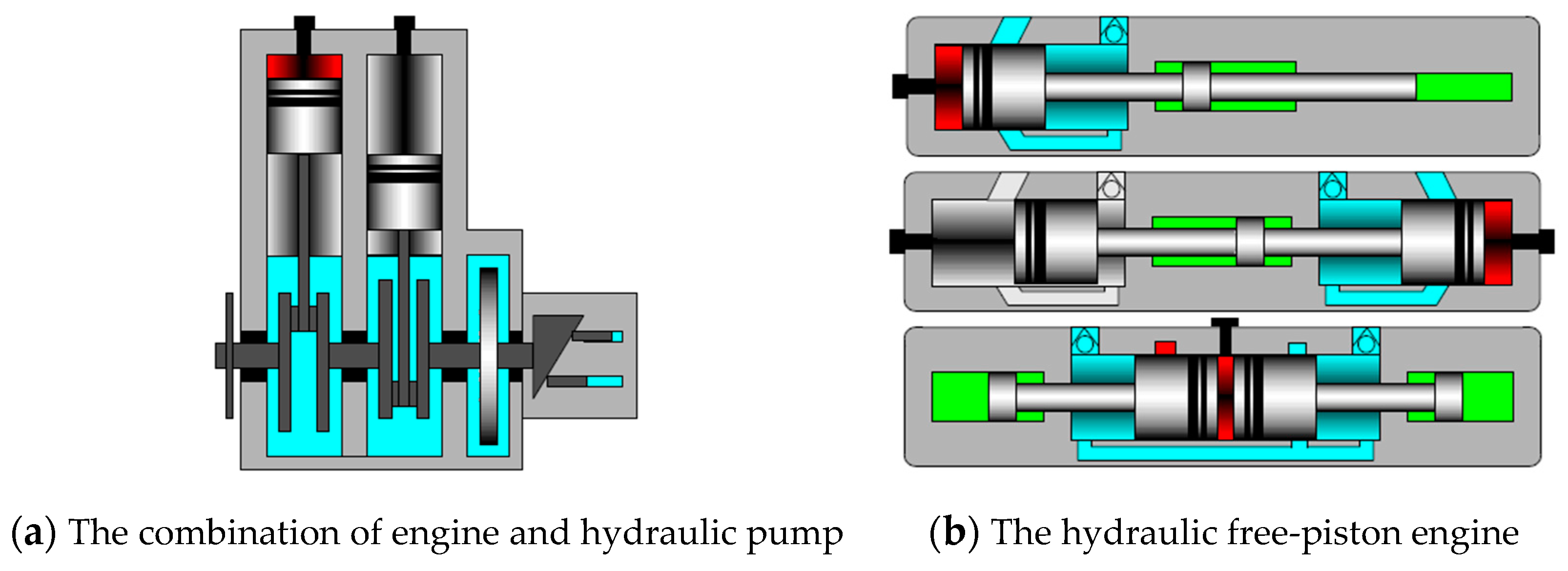
The HFPE is a special engine that combines a reciprocating piston engine with an axial piston pump. By connecting the pistons with a hydraulic plunger, this engine can translate reciprocating motion into hydraulic energy and output power in a non-rigid pattern. An HFPE does not have any crank-link mechanism or oblique plate mechanism; these two kinds of mechanisms are very common in conventional engines and plunger pumps [
4,
5]; the differences between an HFPE and a traditional engine–pump combination are shown in
Figure 1. The HFPE has some advantages, such as a more compact structure, fewer parts and lighter weight; the efficiency of synthetic transmission and friction loss are better than those of a conventional engine. There is also no transmission chain and no lateral force on the piston; therefore, the rule of piston movement, even the compression ratio, becomes adjustable by changing the load applied o then piston. All of these are good conditions for optimizing the in-cylinder combustion process and increasing fuel adaptability. Actually, the HFPE descends from the free-piston engine and carries it forward. It is synthesized by an internal combustion engine, hydraulic technology and electronic control technology [
6]. HFPE development roughly experienced the following stages:
- (1)
Initial stage (1980–1990)
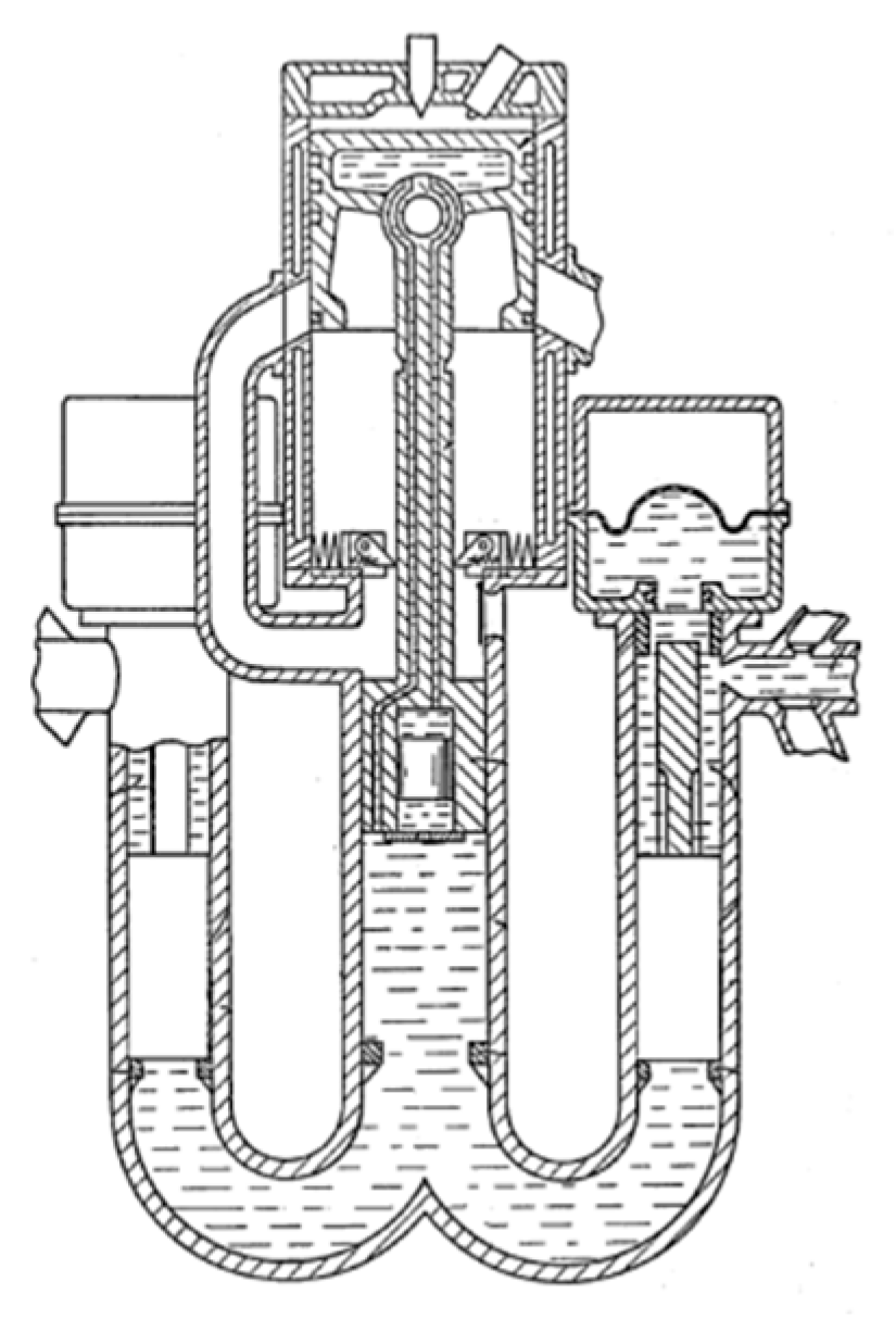
Figure 2 shows a hydraulic free-piston which uses a two-stroke reflux scavenging scheme: its load is hydraulic oil with a certain pressure; a hydraulic accumulator is applied as the energy storage component [
7].
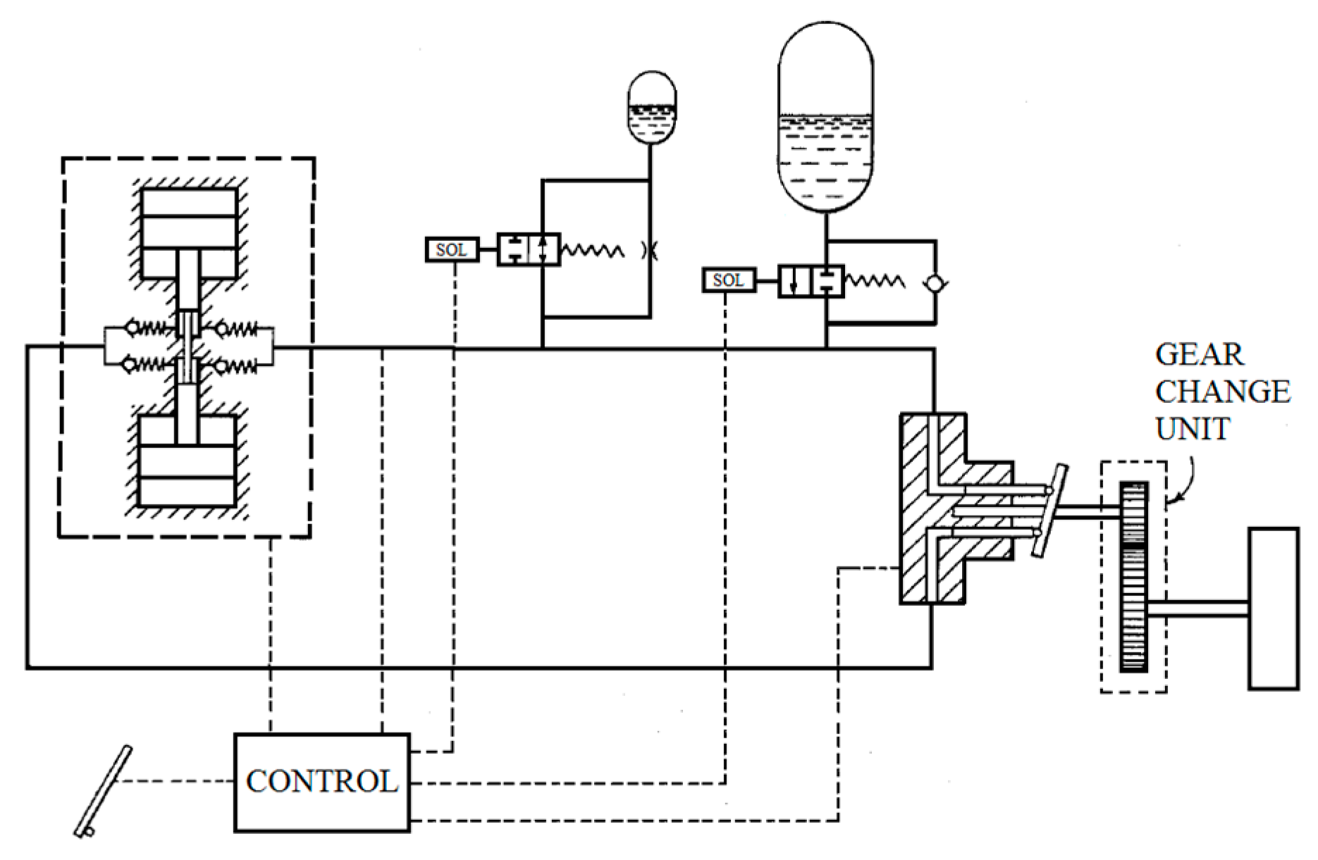
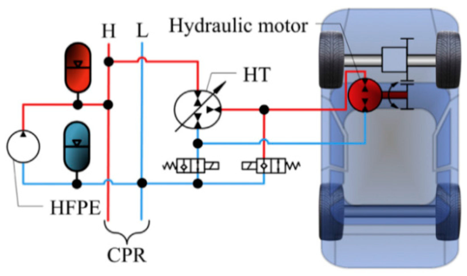
Figure 3 shows a propulsion system, and its power source is an HFPE [
8]; this system uses hydraulic oil produced by a hydraulic free-piston engine to drive one hydraulic motor directly; then the energy from the internal engine becomes kinetic energy for driving the system softly. Many patents concerning this idea stayed on paper, and no prototype was produced because of the bad performance of the hydraulic electromagnetic valves and the poor response of the electronic control systems. The University of Wisconsin and General Motors corporation had proposed projects that were alike; they both established thermodynamic models and dynamical models via computer to verify effectiveness. In the end, they proposed several design schemes [
9,
10,
11].
- (2)
Development stage (1990–2000)
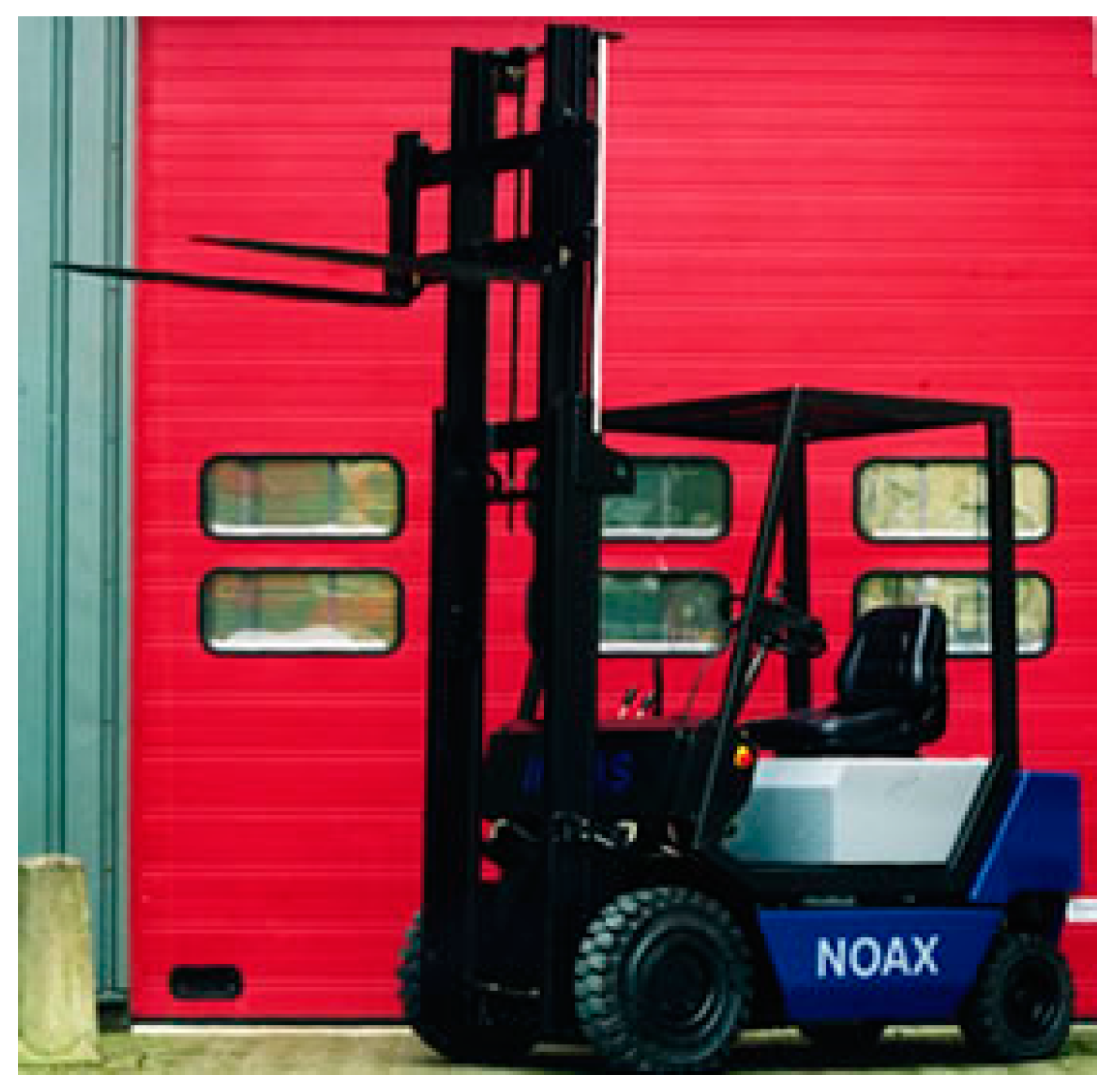
In the 90s, the rapid development of electronic control technology made control of the hydraulic free-piston engine’s hydraulic valve high-frequency response possible. At this stage, mainly in the Netherlands, INNAS and Tampere Industrial University worked on HFPE. The company pioneered the HFPE’s success in small forklifts, cranes and machine–liquid hybrid systems (see
Figure 4 for an HFPE-powered forklift). At this stage, the 5-generation prototype manufactured by INNAS achieved usable results, but the engine had serious problems, such as poor cycling stability and even flameouts [
12,
13]. As shown in
Figure 5, simultaneous trial production at Tampere Industrial University was also able attain complete multiple cycles of operation, but stayed at the prototype stage. In addition, Professor Hibi of Japan (and others in the same period) researched a related piston-type HFPE [
14].
- (3)
Post-development period (2000–today)
In the 21st century, with all the advances in engine and hydraulic systems for electronic control technology, the HFPE’s technical difficulties were resolved, giving HFPE research into new vitality. Zhejiang University [
15], the Beijing Institute of Technology [
16,
17], Tianjin University [
18] and the University of Minnesota [
19,
20,
21] launched HFPE-related research. In the first few years of the 21st century, as shown in
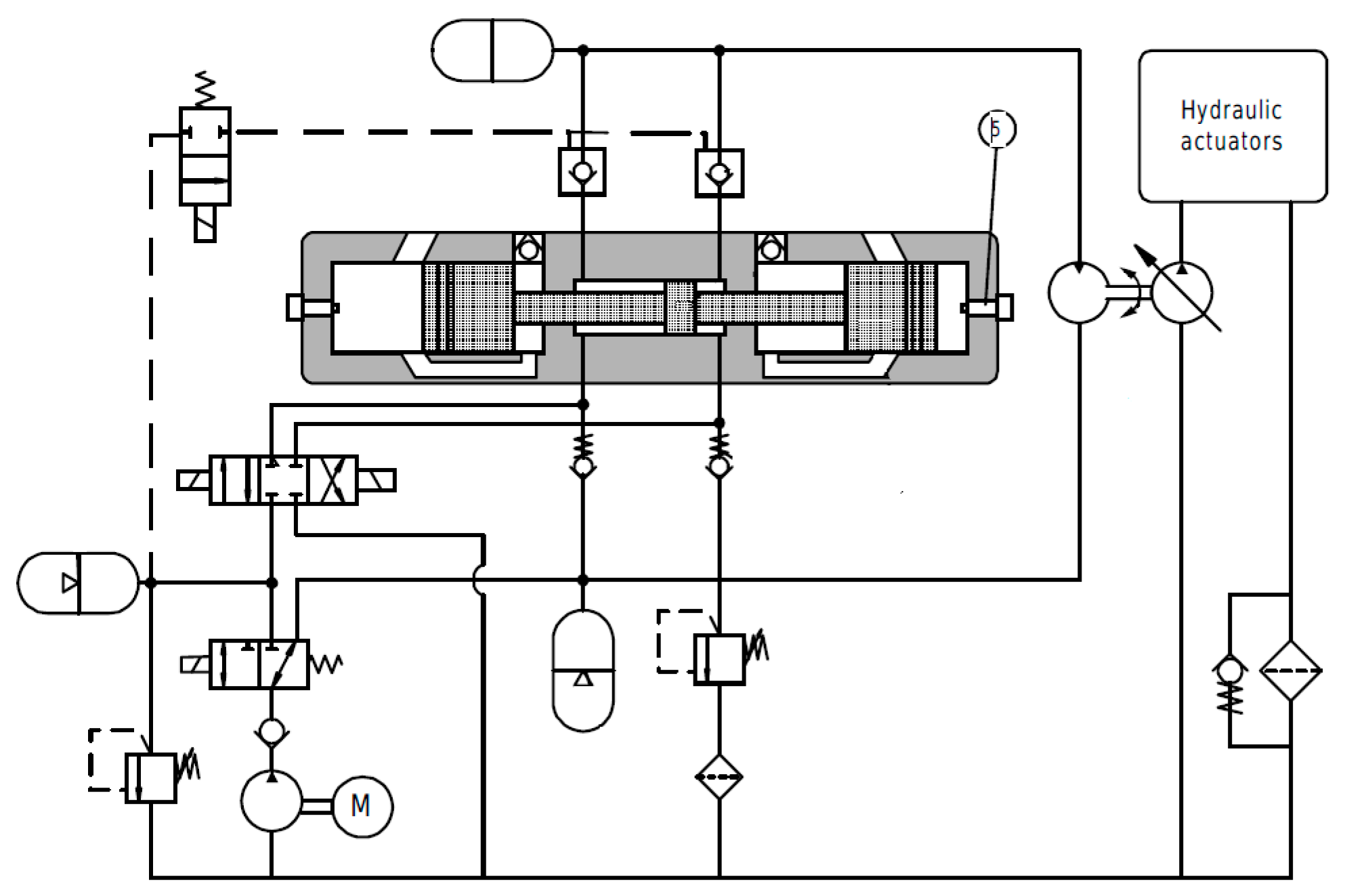
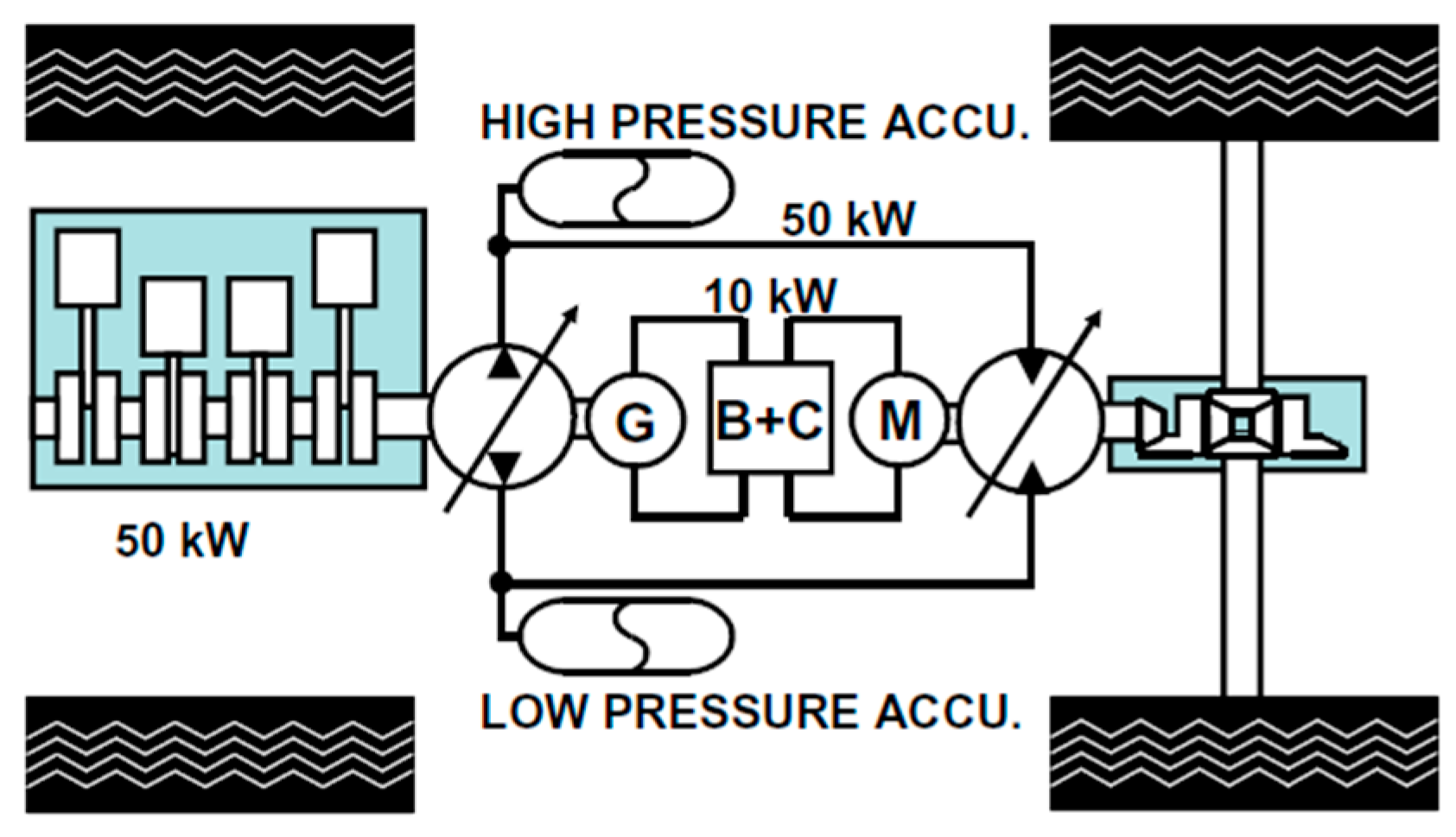
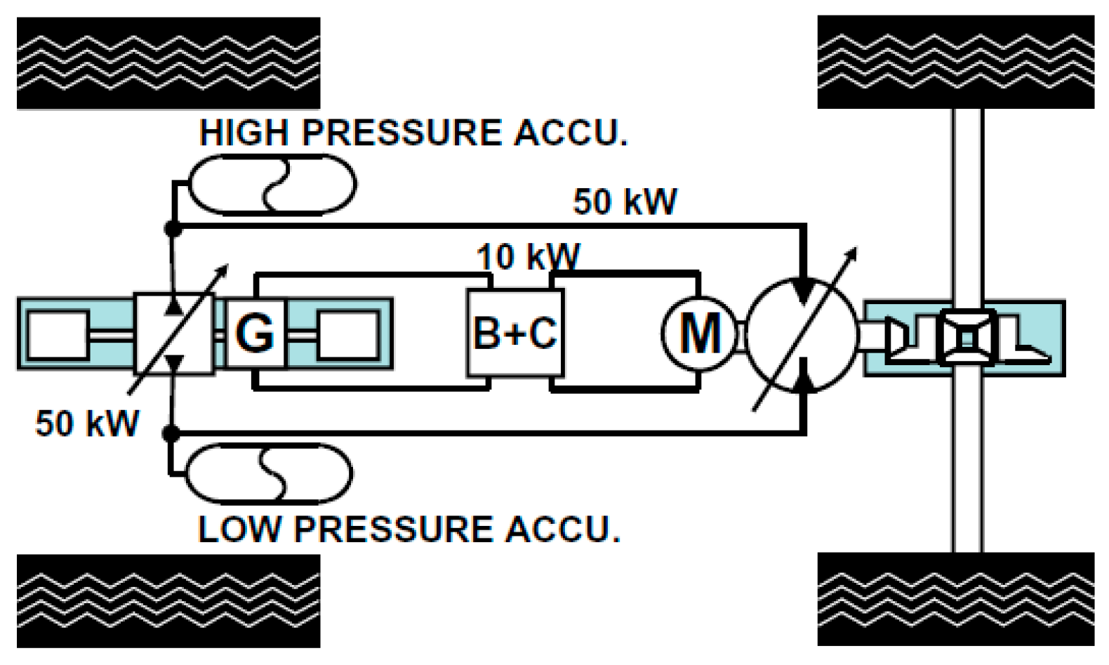
Figure 6, Volumtran proposed, based on a traditional engine power source for the electro–hydraulic hybrid system, a design reaching high speeds with low torque using 10 kW. The motor drives the load and uses a 50 kW hydraulic drive to drive the load at low speed and high torque. The researchers also designed a hybrid system based on dual-piston HFPE as a power source, as shown in
Figure 7. At the same time, INNAS proposed a hydraulic hybrid transmission system; the main components of the system for the hydraulic transformer are shown in
Figure 8. Similarly to INNAS’s liquid–liquid hybrid system, the Beijing Institute of Technology developed HFPE’s hydraulic–hydraulic hybrid system, which was based on the HFPE prototype shown in
Figure 9. The system used the operation strategy of low-speed constant torque and high-speed constant power, which ensured the dynamic, comprehensive performance of the vehicle, thereby expanding the application prospects for HFPE.
2.3. The Working Characteristics of HFPEs
There are some special working characteristics of HFPEs because of the differences between conventional engines and these engines. Among these characteristics, some make HFPEs better than conventional engines.
2.3.1. The Theory of the Hydraulic Free-Piston
The reason why it is called a hydraulic free-piston engine is that the piston is not restricted by crank-link mechanism; the piston’s movement is affected by the force loaded on the piston [
4,
16]. The HFPE contains three systems: an internal combustion system, a load system and a reset system. The internal combustion system usually applies to two-stroke engines because of no crank-link mechanism and a flywheel; the piston moves up and down in a cylinder and outputs hydraulic energy by driving the hydraulic load system [
22]. The reset action can use an independent reset system or thermal energy produced by another cylinder. This engine can use multiple fuels because of its variable compressor, fuel injection and valve timing technology.
2.3.2. The Operational Control of HFPEs
For HFPEs, the power piston movement law completely relies on the force loaded on the power piston. Therefore, it is necessary to finish the design and calculation processes in advance to make sure the piston movement rule is right. This is necessary for any prototype label. The biggest challenge is how to measure the piston position and control the piston movement rule precisely, because the piston position, as the real-time signal for the controller, could decide whether the controller works properly or not.
For a dual-piston, hydraulic free-piston engine, the working frequency is the piston’s harmonic frequency, so the range of working frequencies is relatively tight. The variable frequency output could be realized by changing the load and fuel-injection quantities. For single-piston and opposed-piston free-piston engines, more precise control could be realized because of the independent reset system; the working frequency could be controlled easily by adjusting when to release the compressed energy, and the range of output power is wider than for normal engines. Dutch Achten proposed the pulse pause modulation control method, and this method has been applied widely.
2.3.3. The Starting Characteristic of HFPEs
HFPEs once could not finish starting, depending on the motor, because of the absence of a crank-link mechanism and flywheel. In the middle of the 20th century, this engine could finish starting by compressed air—compressed air entered the spring back chamber by a channel. In this method the first cycle’s ignition could be realized easily, because it could provide a higher compression ratio; however, the heart of the matter was how to control the high-pressure air located in spring back chamber in order to provide enough time for exchanging gases. Some researchers pointed out that it is not vital, although it is hard, to start this engine. The free-piston generator could finish starting by changing its mode to a motor, whereas a hydraulic free-piston engine could use the hydraulic energy stored in a hydraulic cylinder to finish starting.
2.3.4. The Misfire Characteristic of HFPEs
HFPEs are sensitive to in-cylinder operating parameters such as scavenging processes and mixed gas formation during operation [
23]. Achten et al. believed that the HFPE’s combustion process is faster than normal [
13]. Tikkanen also believed that the combustion of HFPE is mainly carried out in premixed combustion [
12]. In fact, the combustion process of HFPE is directly related to the formation of the mixture, which is directly affected by the scavenging process and the fuel injection process [
24]. Further studies have found that the scavenging process and the fuel injection process are related to the kinetic parameters of the cycle of a given HFPE. Once a cycle of combustion fluctuates, it will seriously affect the next cycle’s scavenging and fuel injection process. Major fluctuations will lead to scavenging deterioration, and oil and gas mixing conditions deteriorating, eventually leading to HFPE fires.
2.3.5. Other Characteristics of HFPEs
An HFPE’s balance has a certain impact on its operation, although the opposing-piston HFPE can be self-balancing, but other forms of HFPE have had vibration problems. Generally, improving the balance is a fast, reasonable way to achieve system balance [
25]. In addition, HFPEs are mainly challenged by the lifetimes of piston components. Flynn and others pointed out that, due to the HFPE’s instantaneous heat release, the cylinder pressure rises quickly and the piston acceleration is immense, so piston component failure is mainly via hydraulic piston wear and the destruction of the power piston ring [
26].
3. The Research Status of HFPEs
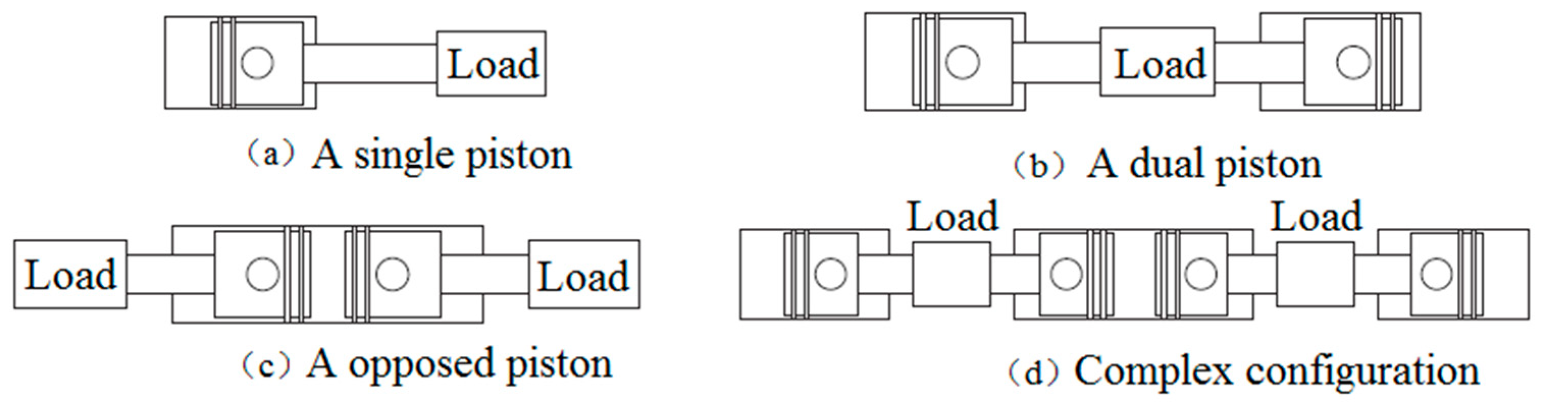
There are four types of free-piston engine according to piston arrangement form [
12,
24]: single piston, dual pistons, opposed pistons and four cylinders complex configuration as shown in
Figure 10.
3.1. A Single-Piston HFPE
Figure 11 shows a free-piston engine with a single piston. This engine is called a hydraulic free-piston engine due to the hydraulic energy outputted by this engine [
27]. There are three components in this engine: the internal combustion system, the load system and the reset system. The reset system can accumulate enough energy during the working process for the next compression cycle. The load system and reset system can use one or two hydraulic cylinders. The biggest benefit of the single-piston, free-piston engine is its simple structure and controllability compared with other free-piston engines. The reset system can control resetting energy precisely, so the compression ratio and piston stroke are steerable, as is working frequency, which is controlled by adjusting the moment of release for reset energy. However, the independent reset system which can increase the engine’s controllability is an obstacle to being more compact. Meanwhile, this engine’s vibrations along the piston-axial direction are violent because of unbalanced forces loaded onto the piston during the working process. Measuring the engine’s parameters, the displacement of the piston especially, is difficult [
28,
29].
Innas BV [
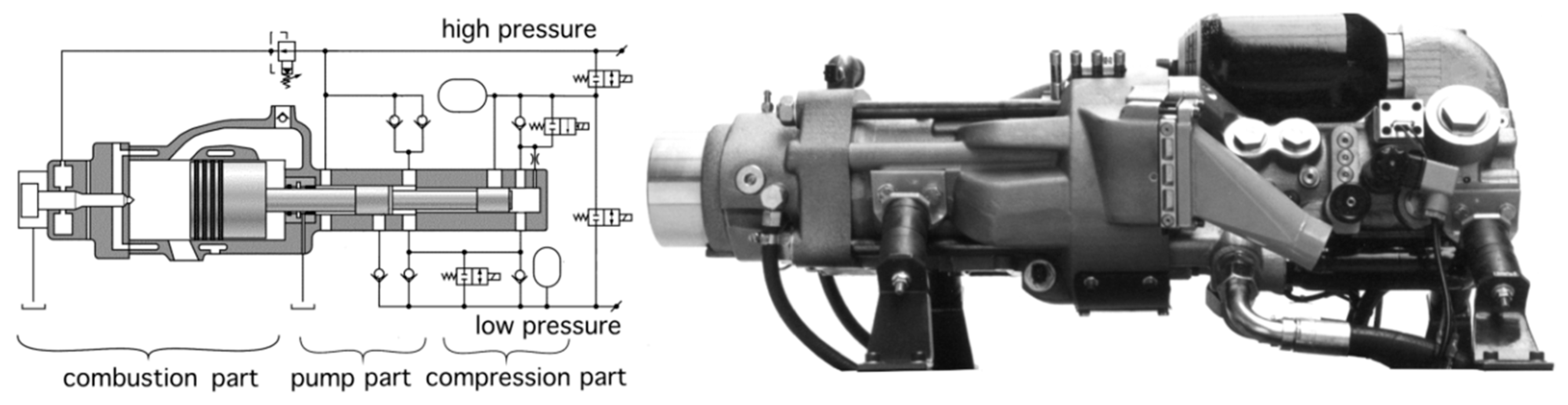
24] from Holland leads the research about single-piston HFPEs. This company, which was already involved this field in 1987, has developed a single-piston HFPE called Chiron; its fuel is diesel. This company is trying to use this engine to replace the combination of a conventional engine and a hydraulic pump, and the engine has been applied successfully in a forklift so far [
30]. The structure and principle of CHIRON are shown in
Figure 12. The structure includes the internal combustion engine part, the hydraulic pump part and the compression part. The rightmost hydraulic piston receives the compression energy of the accumulator through the frequency control valve to complete the HFPE’s piston compression stroke. The intermediate hydraulic piston is used to pump the high-pressure oil, in the hydraulic pump part; the internal combustion engine part is the two-stroke, reflow scavenging, hydraulic, auxiliary HEUI injection system diesel engine. Researchers who study CHIRON argue that there is a cyclical fluctuation in the combustion process of the internal combustion engine, and that some disturbances due to combustion boundary conditions will cause some cycles to fire; and there are problems in the operation of the free-piston engine—e.g., in a working cycle, the energy cannot be successfully pushed to the end of the piston. CHIRON designers assigned to its fire problem designed a special piston rapid return system [
30]. The piston assembly’s return system is rapidly shutting down CHIRON’s fire problem, which lasts about 0.1 s. Since the hydraulic system uses a hydraulic system, the process has little effect on engine performance.
3.2. A Complex Configuration HFPE
The single-piston HFPE is worse self-balanced than the dual-piston free-piston engine. The opposed-piston engine is the best self-balanced, so many researchers from the University of Minnesota made a complex-configuration, hydraulic free-piston engine by combining opposed pistons with dual pistons. This engine connects the air inlet piston and the outlet piston by a linkage; its hydraulic load settings are the same as those of the traditional opposed hydraulic free-piston engine, as shown in
Figure 13. Its combustion chamber does not have a valve mechanism because of uniflow scavenging. For a free-piston engine without a crank-link mechanism, there are not any mechanical or hydraulic accessories to assist with scavenging process, so it will have a more compact structure. The issue about synchronism for the opposed free-piston engine could be solved by the dual pistons which neutralize the hydraulic force produced by the external rod piston [
31].
Zongxuan Sun et al. from the University of Minnesota have studied control methods of opposed HFPEs and the practicability of this new type of combustion. Their principled sample machine is shown in
Figure 14. Due to having no crankshaft, the piston is free, and the piston displacement curve also becomes unstable; this is bad for this engine because of the changes to the fuel injection and combustion phase. The researchers pointed out one control strategy based on a motion locus in order to improve the stability of this engine. However, it is hard to control while the stroke is long and the working frequency is high. In order to solve this problem, scholars proposed two projects: linear feedback control and nonlinear feedback control. Experiments showed that the error between real displacement and the default path was about ± 3 mm for the HFPE without a feedback controller; the error was ± 2 mm for the HFPE after using the liner feedback controller. The experimental results show the error could be controlled in a better range while using the nonlinear feedback controller which is deduced by physical model; the error is then about ±1mm. It is worth of figuring out that nonlinear feedback controller has a stronger effect while the stroke is larger. On the basis of this, researchers tried to apply HCCI to their HFPE, aiming at different piston displacement tracks. They built a chemical kinetic model, a thermodynamic model and a piston dynamic model; and they found that the temperature distribution, output indicator, heat transmission loss and formation of atomic clusters were affected by a different piston movement track. The piston movement rule could be deduced by adjusting some external parameters; this rule could control in-cylinder reaction products and improve thermal efficiency and emissions. This method could be applied to other combustion modes at the same time [
32,
33,
34,
35,
36,
37].
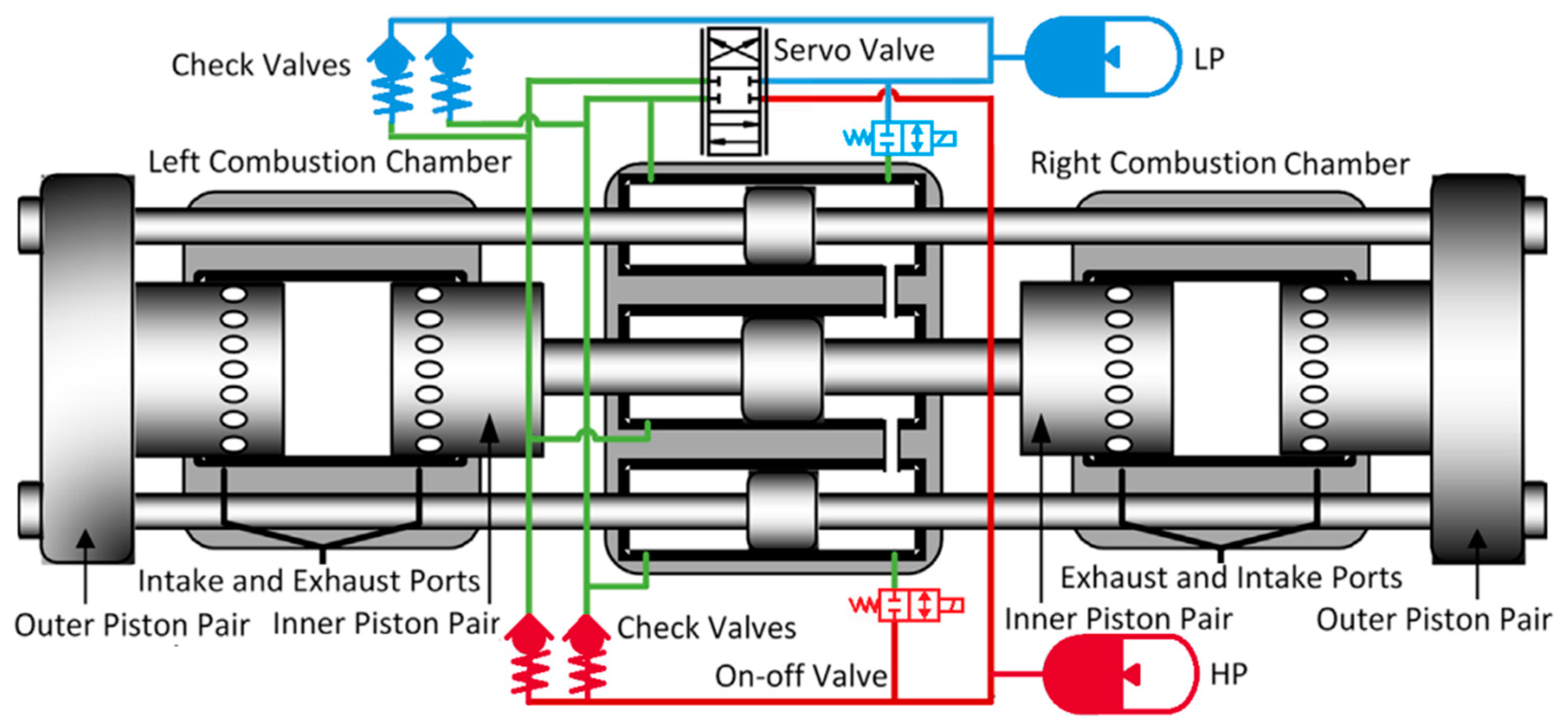
3.3. A Dual-Piston HFPE
There is a kind of dual-piston HFPE which is shown in
Figure 15 [
38]. This engine has two independent combustion chambers; the load systems are electromagnetic [
39,
40,
41,
42] and it uses hydraulic energy [
43]. The output energies are electric and hydraulic energy. The difference between having dual pistons and a single piston is that there is no reset system for a dual-piston engine; the energy for the compression stroke on one side comes from the expansion stroke on the other side, and because of this, this engine is more compact and has higher power density.
In recent years, more and more institutes have focused on this engine and have already attained some achievements. However, there are still some problems puzzling engineers, such as how to control the stroke and compression ratio precisely, and what the movement discipline of the piston is [
44]. Actually, these problems are affected by this engine’s special structure: even a tiny difference during combustion process could impact the compression process in another cylinder. Besides, this engine is very sensitive to load and cyclical fluctuations; a tiny difference in load and cyclical fluctuations may lead to misfiring. In order to solve these problems, some researchers used gear engagement and the multi-cylinder parallelism method, and they made some progress [
45].
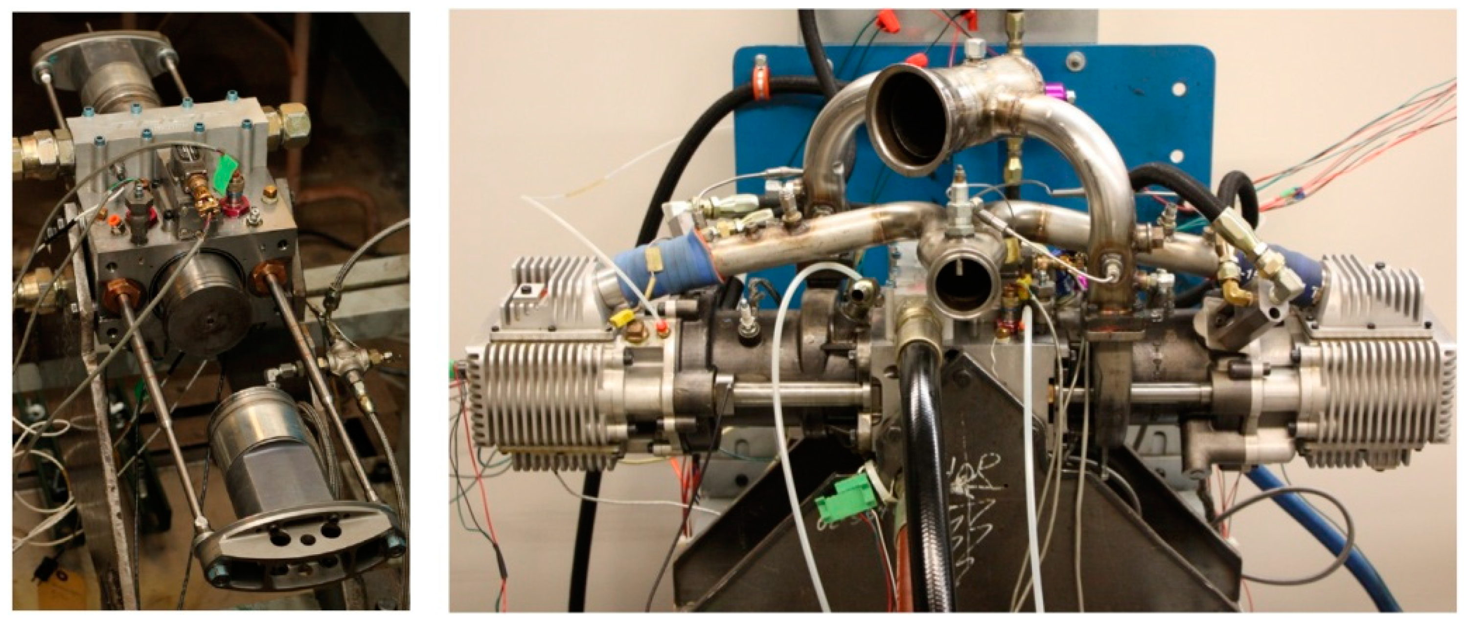
Dual-piston HFPEs are also the current focus of much free-piston engine research; some research institutions have put forward a different dual-piston design, and some prototypes have emerged. The development of a free-piston engine with dual-piston construction was performed by the Tampere TU in Finland [
46]. The prototype principle and the physical model of the prototype are shown in
Figure 16. The prototype was developed. The researchers who analyzed the test results found that the cylinder pressure cycle fluctuations (between 7.7 and 8.8 MPa), caused by the cycling of fuel consumption fluctuations, result in blow-by gas loss. Cylinder pressure fluctuation is the main factor that causes the piston stroke to change. The results show that the combustion process of HFPE is mainly single-peak combustion, and the fuel burned in the post-burning period accounts for about 10–15% of the total fuel injection.
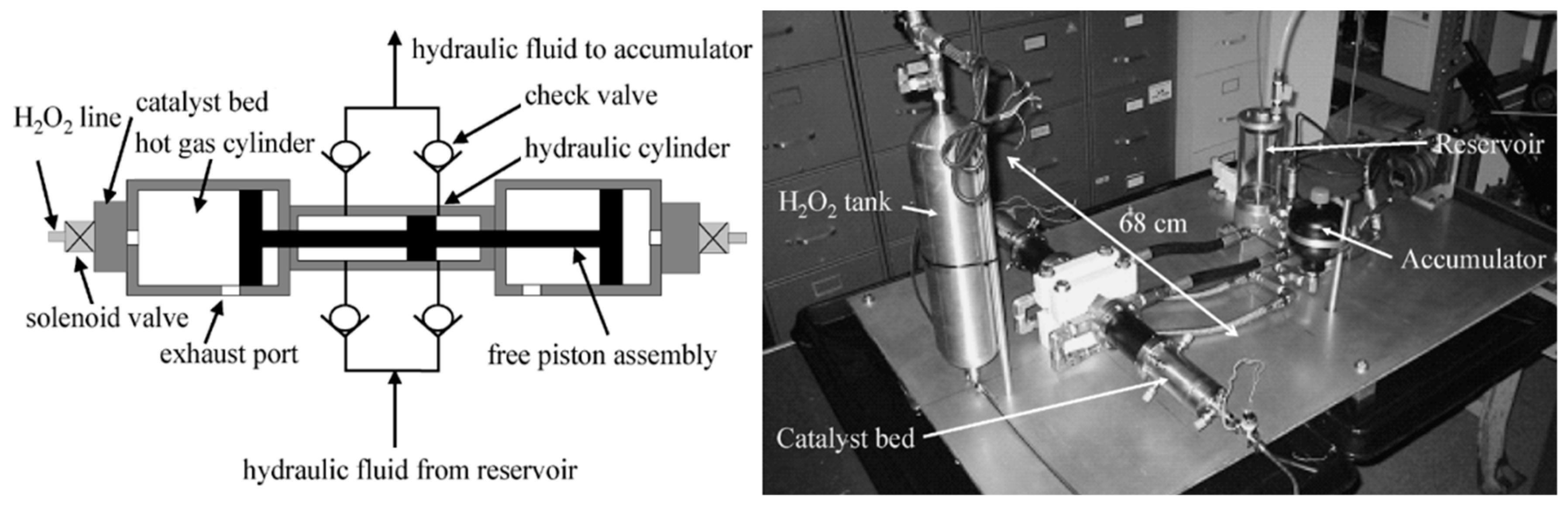
As shown in
Figure 17, similar to this structure is the University of California’s dual-piston, free-piston engine. They developed HFPE as an oxygen-free environment to provide the robot a hydraulic source. The power system can be used underwater and in space, and the original internal combustion engine was different. This engine, according to load requirements to adjust the dynamic output, removed the idle link. The power plant outputs power of 1–3 kW, and its work by-products are only water and oxygen. The engine fuel is a single component, hydrogen peroxide. Hydrogen peroxide, as the catalyst, is decomposed into a high-temperature gas used to promote the piston component’s movement and direct output hydraulic energy. The researchers also made a comparison of the energy of the power system with the battery system, and found that the HFPE was more efficient for a short period of time. In addition, the researchers also performed a thermodynamic analysis of the dynamical system and built a test bench to perform a preliminary study on the performance of the engine [
47,
48].
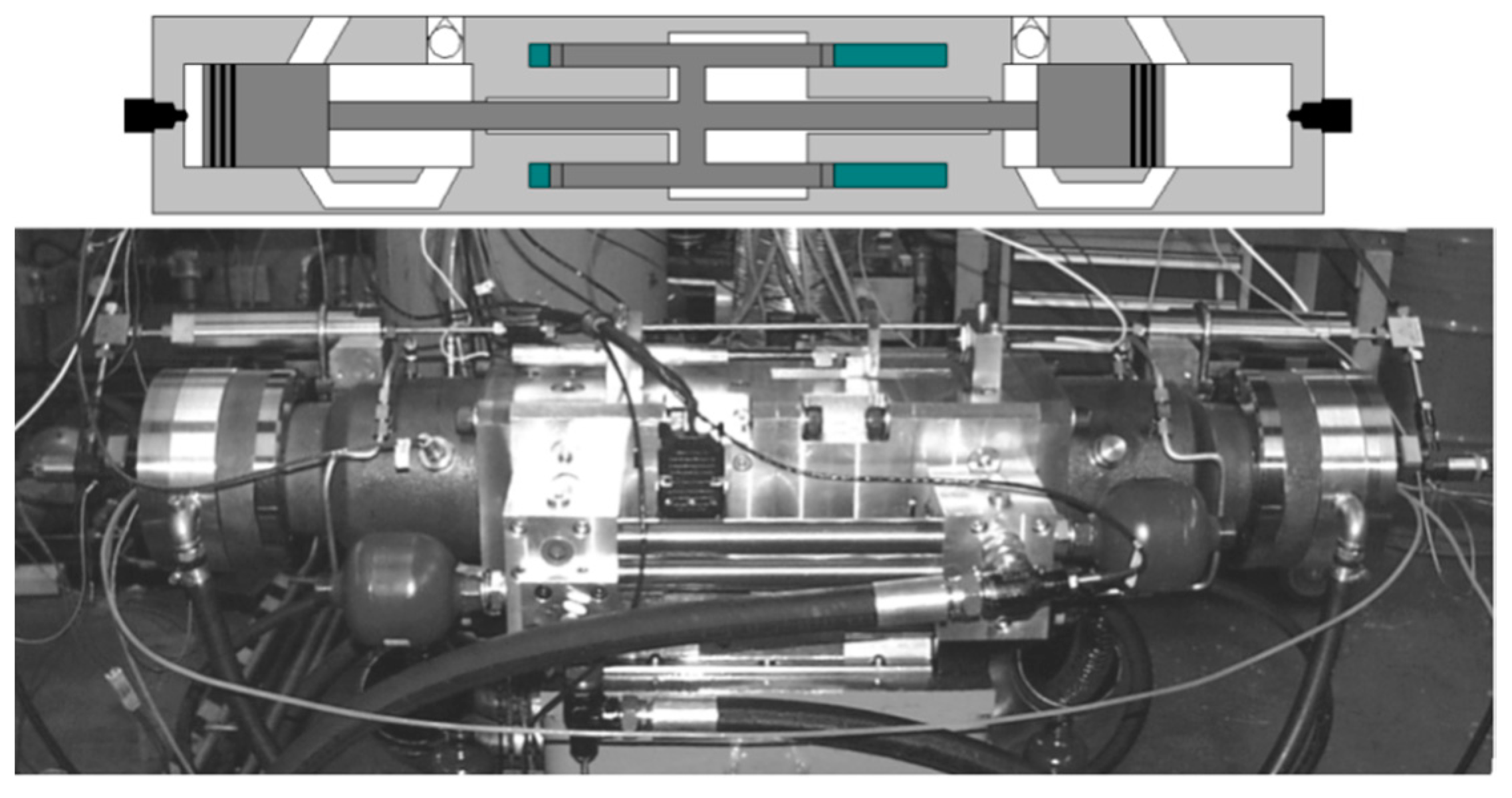
3.4. An Opposed-Piston HFPE
Figure 18 shows an opposed-piston HFPE. This engine owns two independent pistons but just one combustion chamber—two pistons in one cylinder. The main feature is force balance. The damping device could be reduced because of this trait. However, this engine’s pistons demand higher synchronism, so a synchronizing mechanism is usually applied in this engine [
49], yet this makes it more complex. Research about opposed-piston, free-piston engines appealed to many people when the theory was just born (1925–1960), and this engine works via free-piston air compressor and free-piston generator [
50,
51,
52].
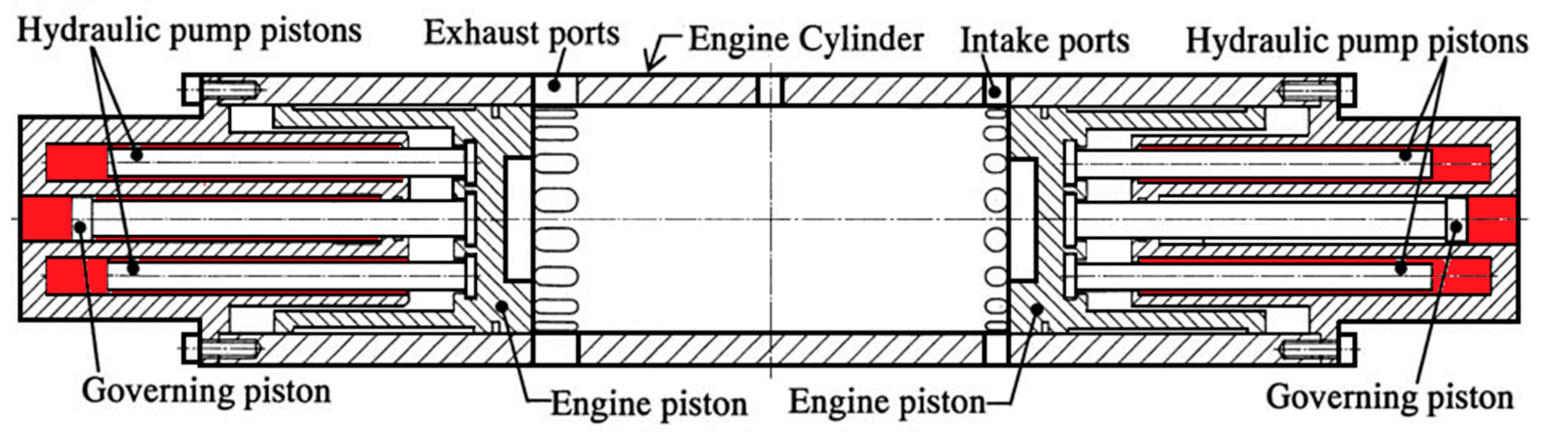
Professor Hibi of Toyohashi Polytechnic University in Japan began to study single-piston HFPEs in 1984 and took the lead in testing the performance. However, eventually Professor Hibi did not continue to study the single-piston HFPEs because of the control problem, but instead began to study the piston-type HFPEs [
49].
Figure 19 shows the HFPE prototype model developed by Professor Hibi et al., which uses two sets of the same dynamic piston and hydraulic piston assembly. The hydraulic piston of each piston assembly is divided into three. The external pump chamber piston is used for high-pressure hydraulic oil output, and the intermediate control piston for piston assembly compression. Professor Hibi’s research team achieved operation of the piston-free-piston engine, and analysis of the cylinder pressure and piston displacement took place.
3.5. Other Types of HFPE
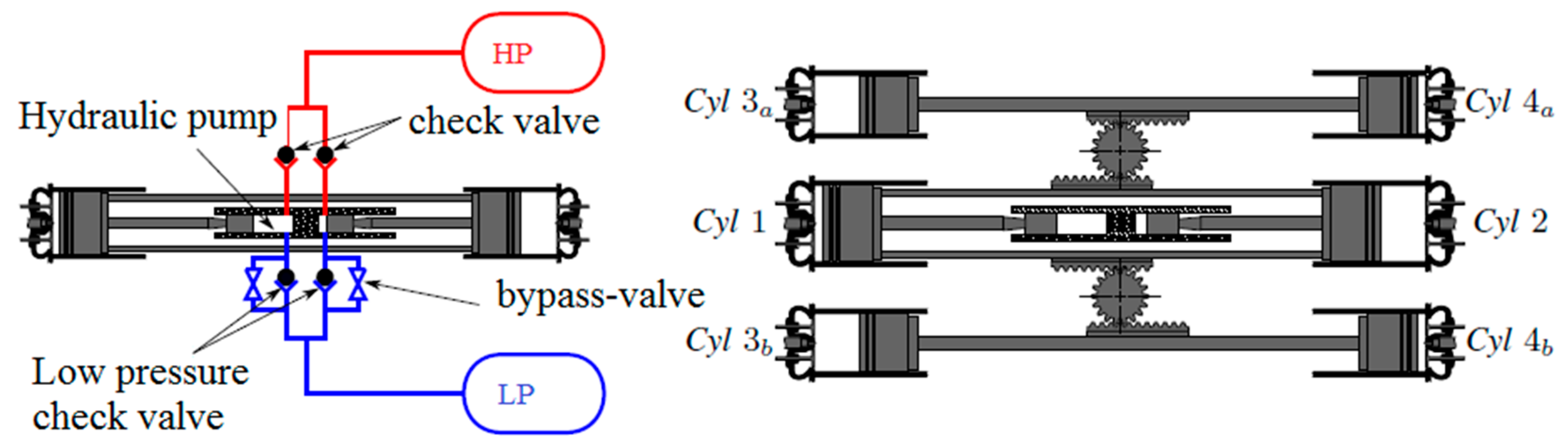
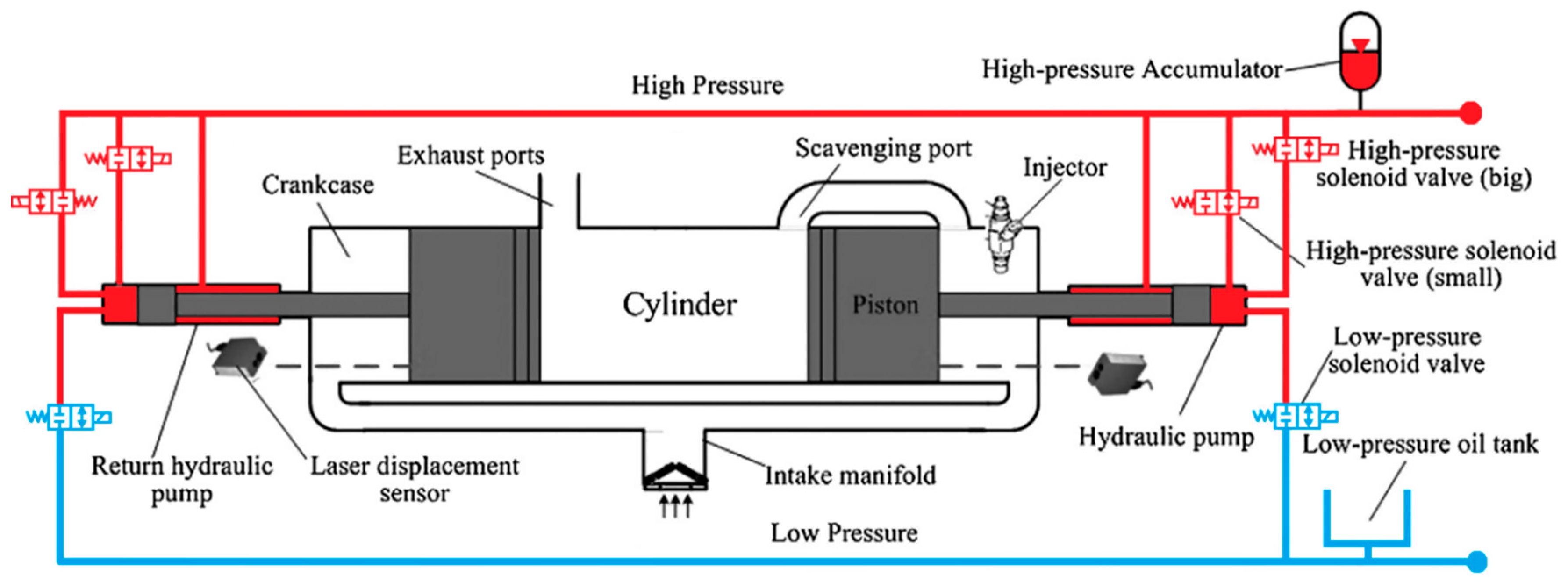
As shown in
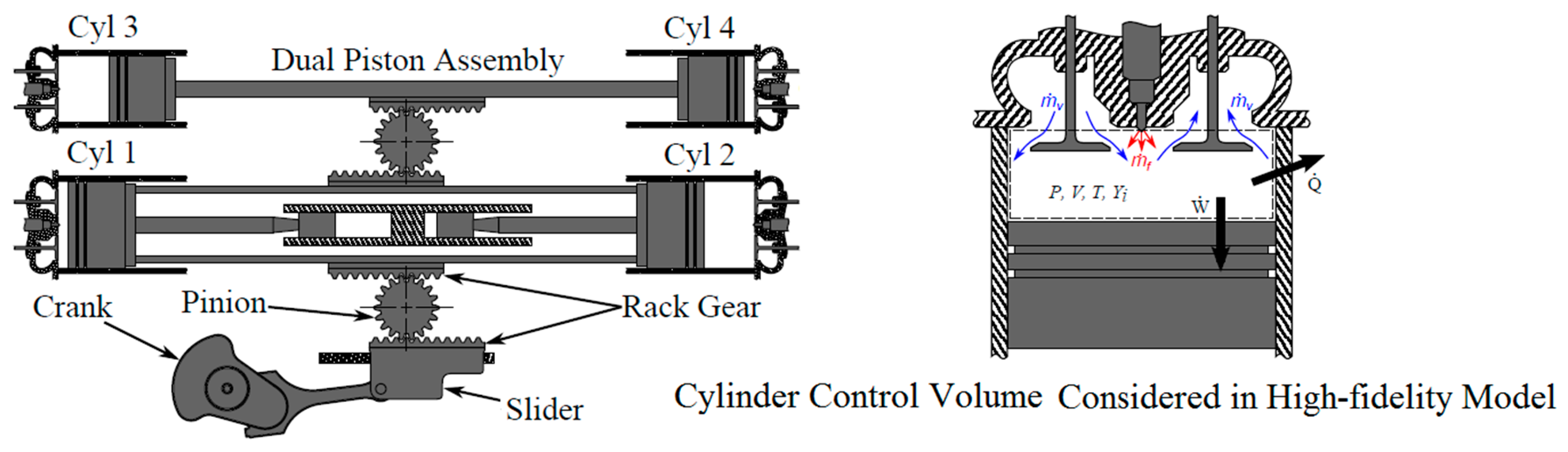
Figure 20, the United States Environmental Protection Agency developed a multi-cylinder HFPE together with the University of Michigan. This engine has six cylinders without sparking plugs; each cylinder has four strokes; the fuel can be injected into each cylinder directly; the efficiency of this engine could be 39% while it is working under continuous and stable conditions; the literature has described this engine and offered test results. However, the engine has bad stability, and in order to improve its stability, Kevin Zaseck et al. applied pinion and rack to drive this engine [
53]. The crank-link mechanism connected with pinion and rack could drive an intake and exhaust system. This engine could produce hydraulic energy via linear hydraulic pump. This method would lead to an unbalanced situation even if the moment of crank inertia is very small. Researchers applied an adaptive algorithm to make sure the kinetic of crank could be changed along the set-points; actually, almost all disturbances were eliminated successfully when the rotational speed was 1000 RPM; in addition, this algorithm could handle the situation in which each cylinder had its own load [
45,
54].
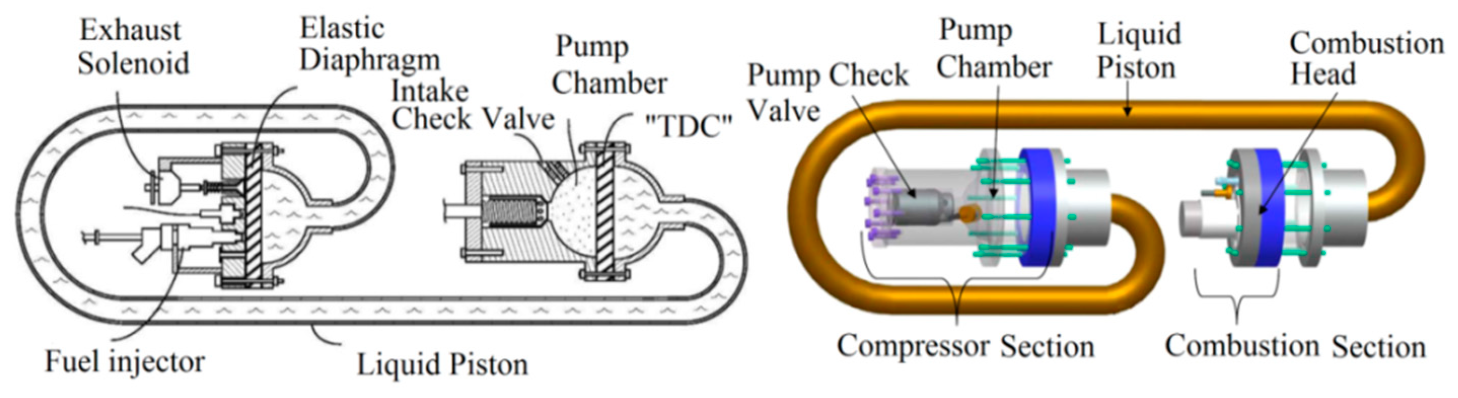
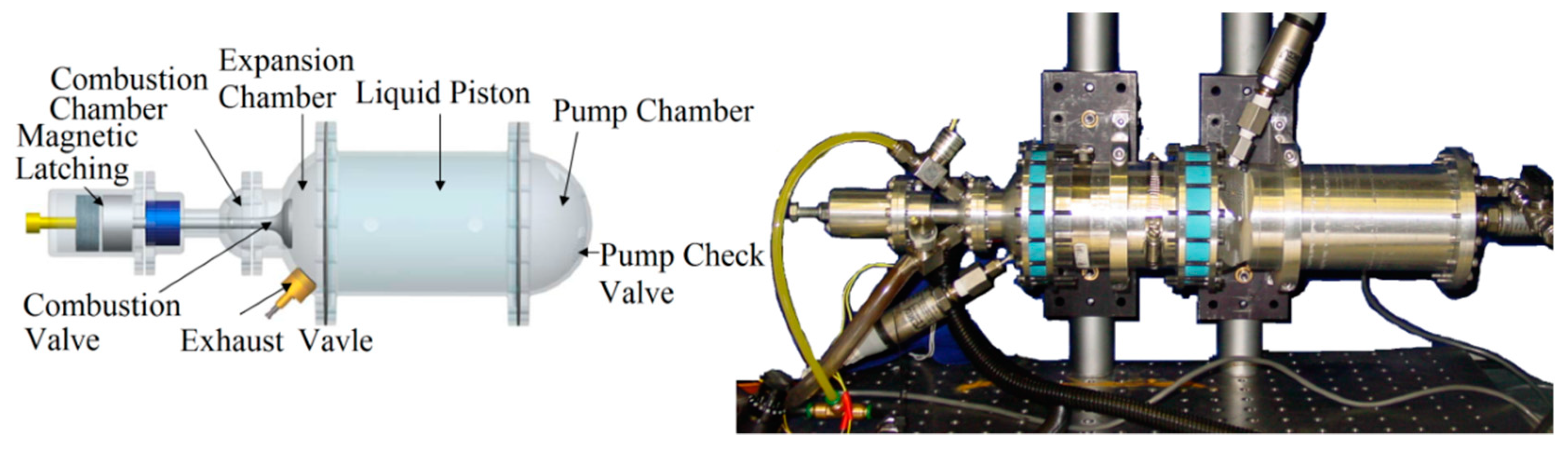
As shown in
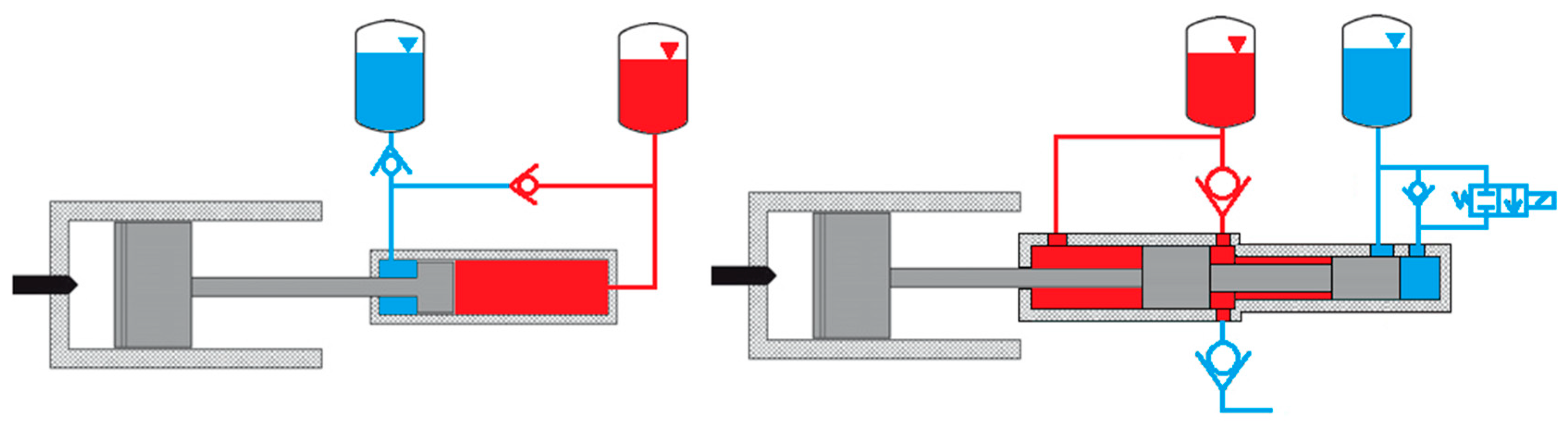
Figure 21 and
Figure 22, the structure of HFPE is mainly about a rigid piston and a hydraulic pump; the hydraulic pump producing high-pressure oil is pushed by the rigid piston. Both the University of Michigan and Vanderbilt University offered their own new free-piston systems. The traditional electromechanical hybrid system can be replaced by these systems because of higher energy densities. These researchers developed a compact, portable and high efficiency free-piston compressor; they also established mathematical models and prototype test platforms at the same time. Based on the test platforms and math models, researchers could assess engine characteristics impacted by dynamic behavior of the hydraulic pistons [
55,
56]. Each system could offer enough energy to drive machinery which is as large as an adult. The combustion chamber and compressor chamber are connected by two rigid pieces of diaphragm; the expand diaphragm in the combustion chamber works as a free-piston because of the flexible characteristic of the incompressible fluid. This method not only handles the sealing problem, but also reduces the friction loss. Actually, this dynamic device is a tunable resonator, so choosing the right resonant frequency, inertia of liquid and elasticity of the diaphragm is very important. In addition, the engine’s dynamic characteristics could be ensured by applying reasonable inlet and outlet valves [
57,
58,
59].
3.6. Domestic Status
In China, there are many universities and institutes that have studied HFPE; they include Tianjin University, Zhejiang University, Jilin University and the Beijing Institute of Technology. Zhejiang University and the Beijing Institute of Technology developed a dual-piston HFPE, and an opposed-piston HFPE and a single-piston HFPE, respectively.
3.6.1. Zhejiang University
The key laboratory of fluid transmission and control in Zhejiang University developed a first-generation dual-piston HFPE. Its engine is a two-stroke gas engine installed in an NF125FDI motorcycle; they have made some achievements in some areas, such as the starting process, energy distribution, dynamic characteristics research and prototype development. In recent years, Zhejiang University has developed single-piston, two-cylinder, inline, four-stroke HFPE, as shown in
Figure 23. There are two strokes in one working cycle; each cylinder finishes a compressor stroke, expands the stroke, exhausts the stroke and inputs a stroke after two working cycles. This engine has low emissions and low fuel consumption [
60].
3.6.2. Tianjin University
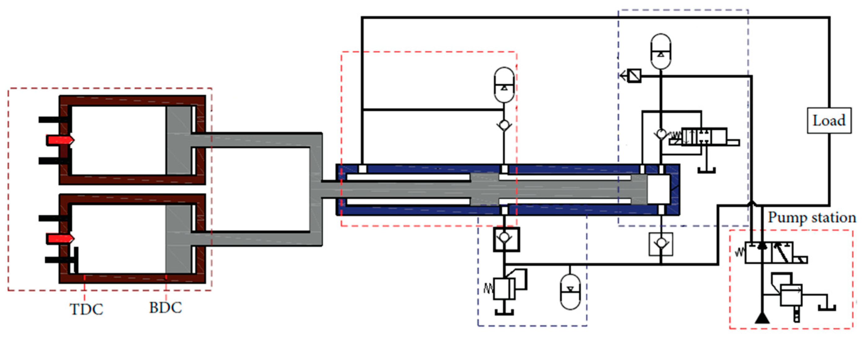
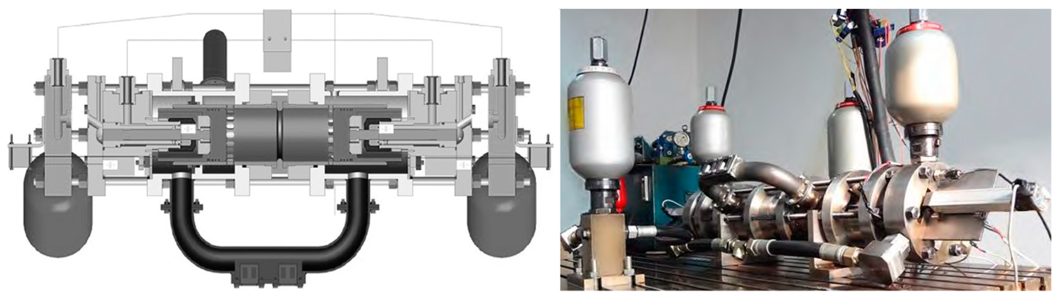
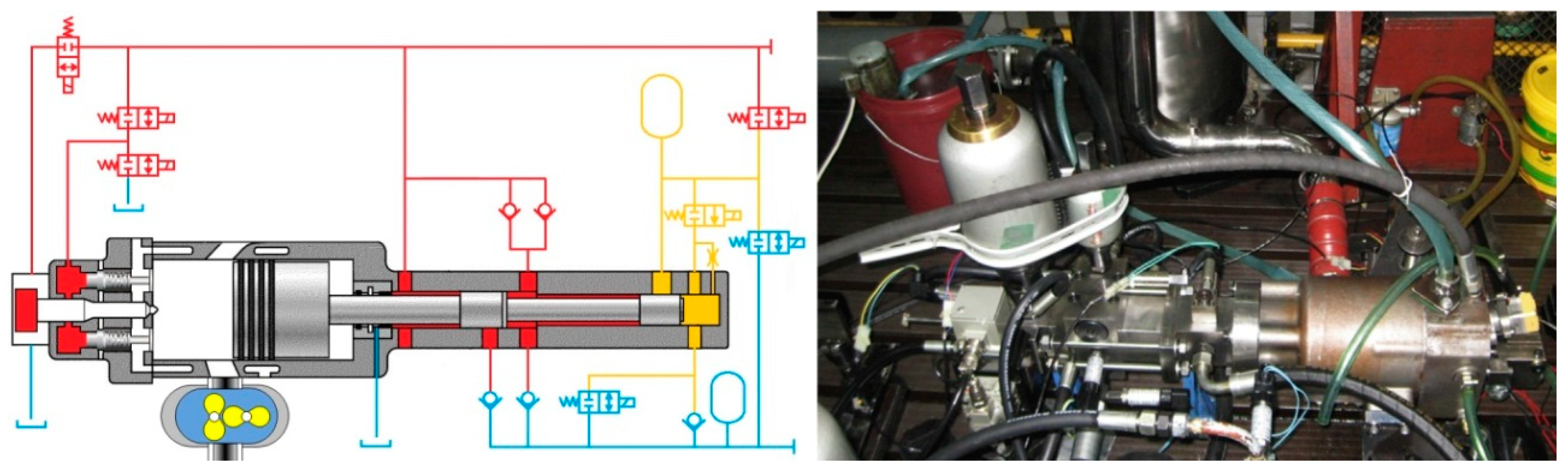
The Internal Combustion Engine Institute of Tianjin University proposed a project about opposed-pistons, two-stroke HFPEs, as shown in
Figure 24. There are two pistons in one cylinder; these two pistons are driven by a hydraulic system and combustion gas in-cylinder without any mechanical joint. A gas exchange system applies the combination of uniflow scavenging and crank case scavenging. HCCI combustion could be applied by the advantage of an adjustable compressor. Besides, experts confirmed the relationships between piston movement characteristics and the coefficient of scavenging, strokes of the engine and the maximum allowed compressor; and they proposed a control method to command synchronization symmetry piston motion: combining the PI feedback control and feedforward control used to predict piston movement [
61].
3.6.3. Jilin University
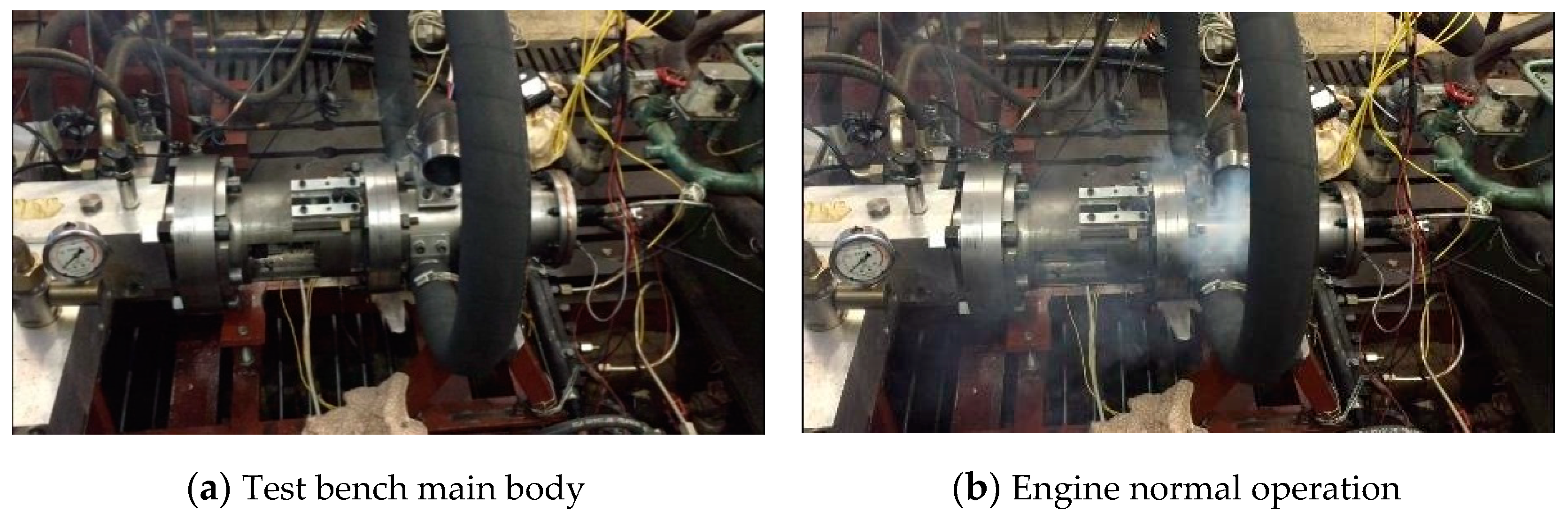
Yuan Zhaocheng developed a monitoring system aimed at HFPEs based on a test bed. He made a starting test by connecting an ECU and an engine to verify whether a controlling method is available; the result was positive.
Figure 25 is the test bed and the graph about the starting test. The HFPE has one difference compared with the conventional engine: The position of the BDC is significant for the compressor ratio and working frequency. Due to this, researchers analyzed prototype stability by describing the buffer measures and position controlling measures [
62]. There is one thing deserving of attention for saving the computing cost of control system. It is worth noting that Gongxun proposed a control strategy about the piston movement based on an iterative reference governor algorithm. By lowering the computing cost of the control system, he unwittingly expanded the method to the application of the implicit system; the online computation speed of control system improved apparently after meeting constraints. In the future, this control strategy will have more reference values for evaluating model predictive control and the effect of the iterative reference governor algorithm [
63,
64].
3.6.4. Beijing Institute of Technology
Beijing Institute of Technology (BIT) has already input huge human and material resources for HFPEs. Since 2005, there have been two generations of single piston linear motion pump—a single-piston HFPE has been developed. Both of them applied diesel injection, uniflow scavenging and a cone valve. The results from researches show that the movement of the piston is decided by in-cylinder gas pressure and hydraulic oil pressure. It could also be affected by diesel combustion and the response of the cone valve. The diesel combustion process is similar to the isochoric process. The system has other disadvantages, such as the huge fluctuation of piston movement, being easy to stall, low power density and low efficiency of the cone valve [
65,
66,
67]. BIT has made great contributions to simulating HFPEs, which is important for prototypes. The second-generation prototype is shown in
Figure 26. After making sure this engine could operate steadily, the researchers discussed the characteristics of the starting process, circulative fluctuation and circulatory stability, and they have performed lots of experiments [
68].
4. The Core Question and Research Progress
The free-piston engine has existed for over 100 years, but the research about the working process lags behind. Until recent years, the working process could not be established; modern methods such as modern analysis tools, simulation software and CFD enabled this change.
4.1. The Research Progress on the In-Cylinder Thermodynamic Process
In order to achieve higher thermal efficiency and lower emissions, A.P. Kleemann et al. established the uniflow, scavenging, free-piston 3D calculation model in order to achieve higher thermal efficiency and lower emissions, as shown in
Figure 27. They tried to use HCCI technology with EGR and in-cylinder injection to optimize the formation of a mixture. The assumption of the researchers was that the discipline of heat release is related to gas exchange systems and fuel injection systems. In order to verify this assumption, they came up with one calculation model which was obtained by coupling a 0D model and a CFD model, a simplified 3D model. In order to achieve better designs for inlet and outlet ports, they choose thermal efficiency and emission performance as optimizing indexes. The simulation showed that over 50% heat release, low soot and low NOx could be achieved via a higher compressor ratio, a higher EGR ratio and HCCI combustion mode.
R. Mikalsen reckoned that 0D could study the basic dynamic characteristics, but it is useless for in-cylinder flow movement and emission characteristics; besides, whether a thermodynamic model that applies to conventional engines is suitable for free-piston engines is unknown. In order to study this engine’s specific performances and potential advantages, it was necessary to establish a 3D simulate mode obtained by coupling with in-cylinder working process and dynamics. R. Mikalsen used OPENFOAM software, a premix combustion model and the CHEMKIN chemical dynamic kinetic solver for establishing a simulation model combined with kinetic and 3D CFD. He finally got the relationship between piston dynamics and in-cylinder flow. He used this model to explore the traits of piston movement, compression energy, ignition timing and ignition duration, and all of these affect the thermal efficiency. On the basis of previous research, R. Mikalsen tested emission characteristics, predicted piston control and finally made a comparison between a free-piston engine and a conventional engine [
69,
70,
71,
72].
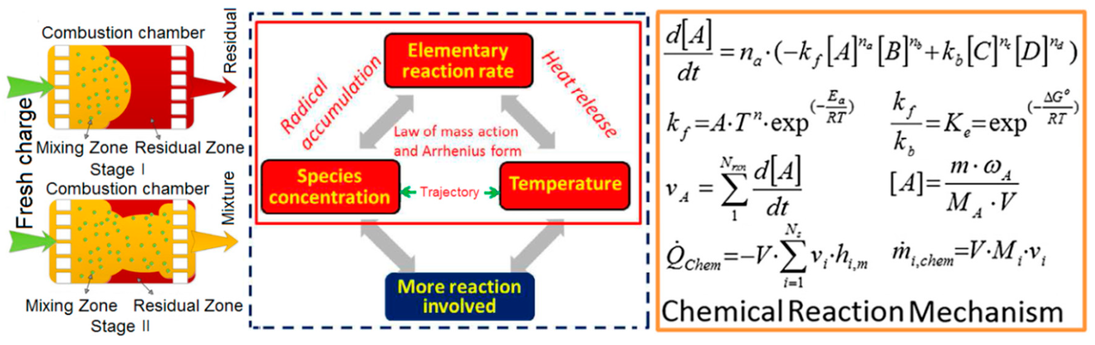
Sun Zongxuan at the University of Minnesota and his fellows explored the in-cylinder working process on the basis of a prototype which they developed by themselves. They proposed the Benson air renewal system. Besides, they thought that the air components in-cylinder and temperature affected the chemical reaction rate directly: the higher speed of reaction, the more atomic groups. The relationships among these factors are one positive feedback system, and this positive feedback system could be strengthened when in-cylinder temperature and atomic groups are specific, and this would increase the in-cylinder temperature eventually, as shown in
Figure 28. The experts explored the interactive model to figure out the relationship between the thermodynamics and dynamics. Some dynamic parameters such as volume and volume change rate, supported by piston trajectory, are the boundary conditions for chemical kinetics. When the temperature and pressure from chemical kinetics are input into the dynamic model again, these parameters can be applied via heat transfer model as the temperature and pressure condition at the same time [
32].
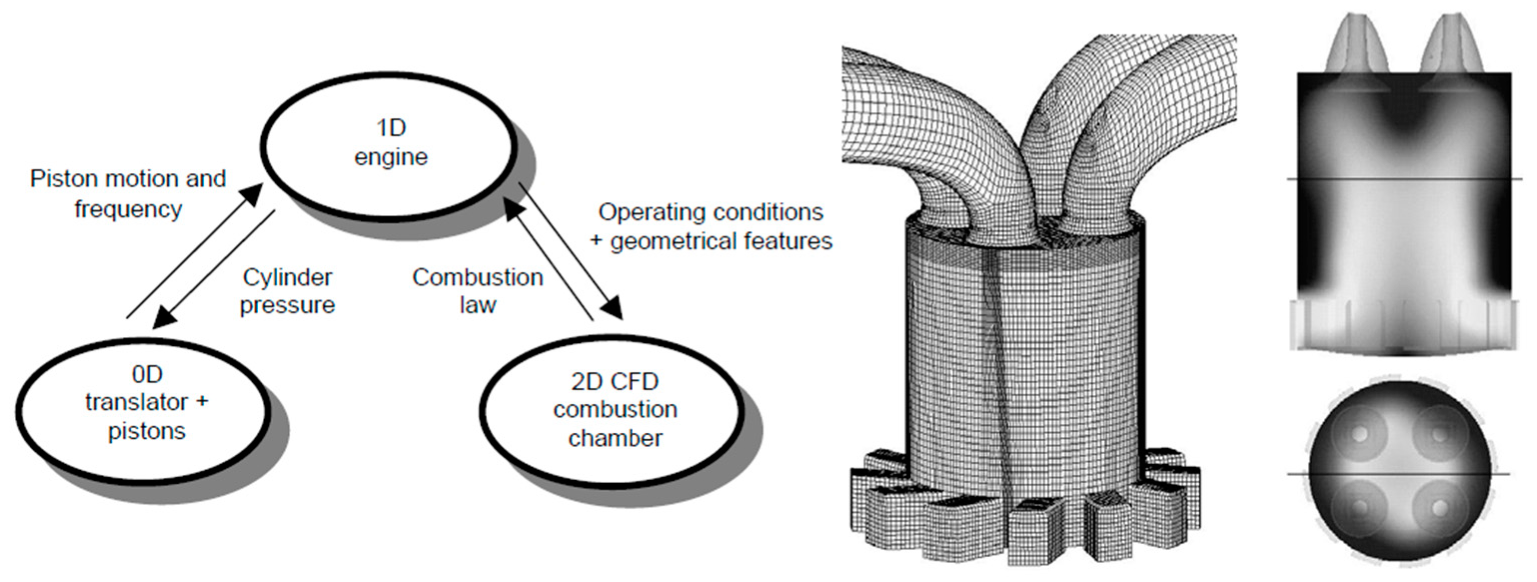
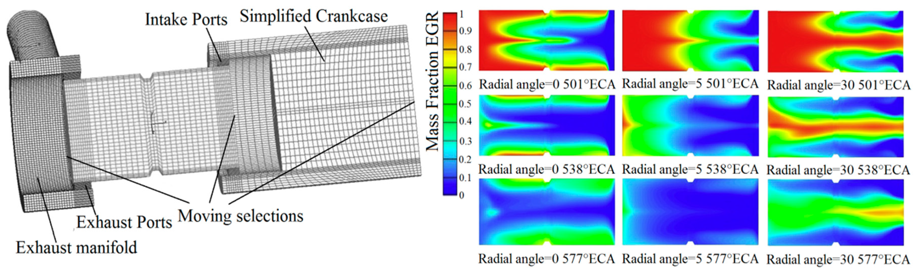
Wang yang et al. used Amesim to establish a 1D simulation model about an opposing-piston, two-stroke HFPE to research the coupling relationship between the gas exchange process and piston dynamics. They had established a CFD simulation model, as shown in
Figure 29. The research results showed that controlling exhaust flow could improve exchanging performance, and that optimizing the exhaust pulse could improve the volumetric efficiency.
The HFPE is a new type of engine, so researchers should start from an external dynamic model to explore the relationships between external dynamics and in-cylinder working processes. There are still many problems with those relationships and the control strategy.
4.2. The Research Progress on the Working Stability of Free-Piston Engines
The free-piston engine has an instinctive problem: stability. Before the engine can come into use, this problem has to be fixed. Finding out the factor which affects the stability is very important. Almost all relevant researchers use simulations and experiments to analyze external dynamic characteristics which affect the free-piston engine [
73,
74,
75,
76,
77,
78]. Researchers are willing to choose the piston replacement as the controlling object because of the feature of this engine. However, some studies reckon that piston velocity is better for better engine characteristics [
79,
80].
In the current research, the study of the stability of the free-piston is divided into several aspects:
- (1)
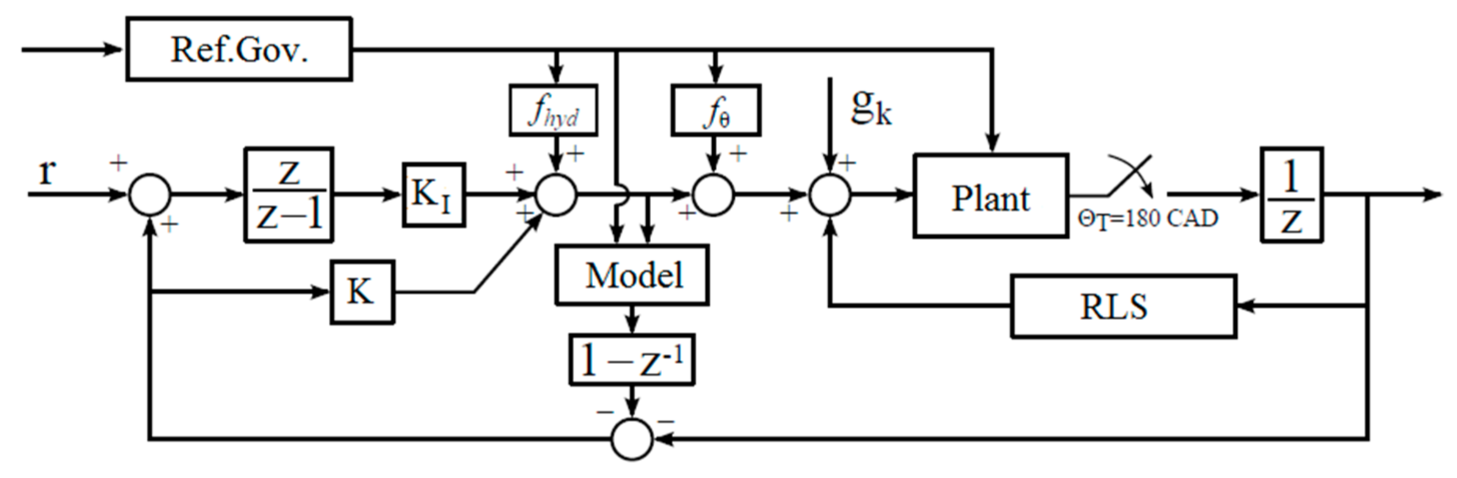
Using the additional mechanical structure, to suppress the freedom of the piston, the method can improve the stability of operation to a certain extent, but the engine attachment system is more complex, in contrast to the simple structure of the free-piston engine. Three sets of dual-piston, free-piston diesel engines for the rack and pinion link were linked together for a hydraulic free-piston engine; the researchers aimed at a free-piston engine system with additive constraints. A reference governor piston motion controller was designed under the framework of discrete events. The researchers used the fuel injection as the control variable and the piston, bottom dead-center position, as the controlled quantity, through the simulation model established. They found that the piston compression ratio can track the expected value well, and the load changes, so that the piston position fluctuations can be within the scope of the constraints, thereby enhancing the stability of the engine. The control block diagram is shown in
Figure 30. In addition, the double piston free-piston engine system is prone to vibrations and uneven movement. Therefore, the researchers proposed a corresponding adaptive control method to identify interference with the system online and to reduce the fluctuations of the piston movement caused by the changes of the load by controlling the fuel injection per cylinder per cycle [
44,
54].
- (2)
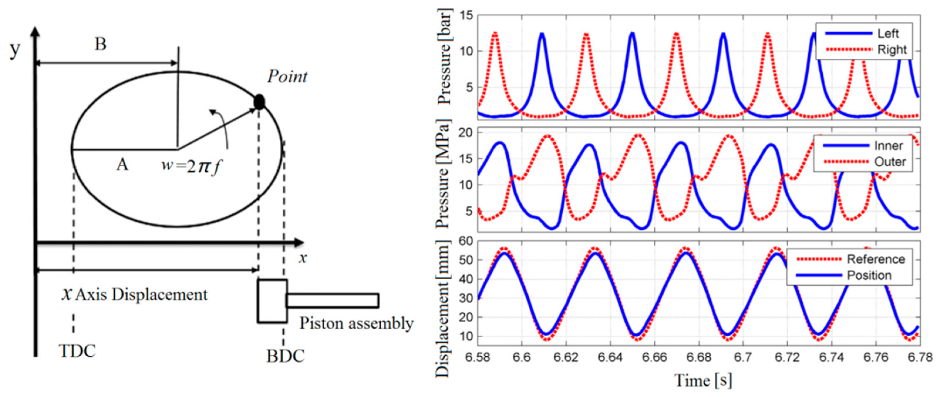
By the virtual crankshaft technology, free-piston engine piston displacement trajectory can be measured for real-time control [
33,
36]. The method can get good results, but increases control difficulty. The control method proposed by the University of Minnesota uses the design of PID controllers to adjust the fuel injection to achieve the purpose of controlling the engine compression ratio. At the same time, those researchers proposed a robust control scheme for the piston motion which tracks the pre-given path. The hydraulic pressure in the hydraulic chamber is adjusted by the servo solenoid valve to achieve the purpose of the active motion control of the piston. The experimental results show that the control scheme can make the piston more accurately track the given path, and
Figure 31 shows the virtual crankshaft and piston displacement trajectory tracking. Since the control scheme relies on a given piston motion path and the given path is determined by the engine’s real-time load and compression ratio, it is difficult to give a more accurate tracking path in practice.
- (3)
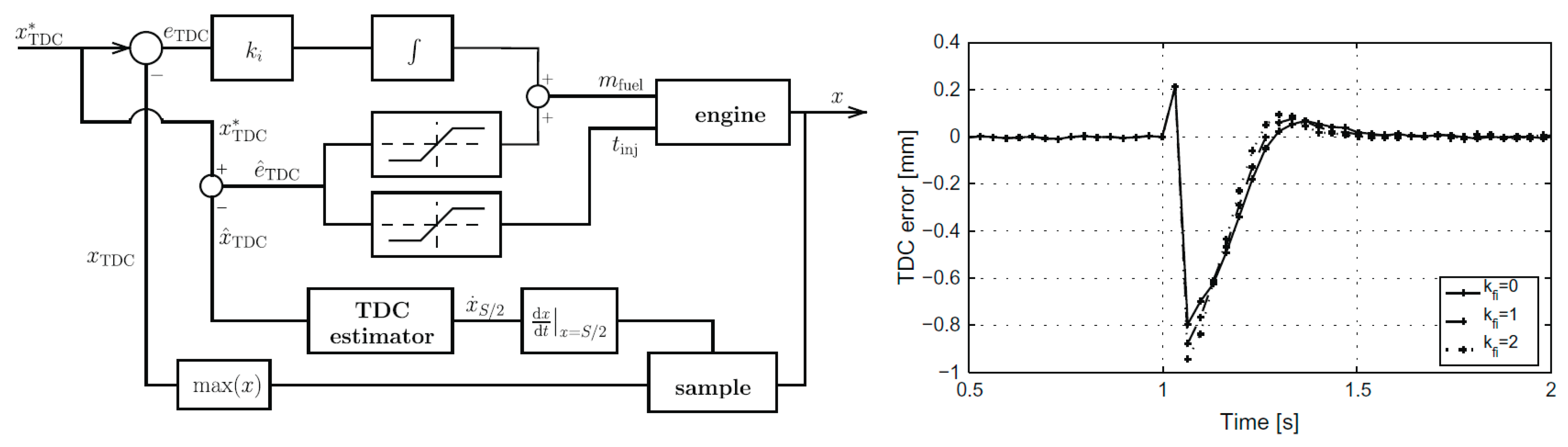
By modern control theory, the establishment of the relevant predictive control model [
81,
82] by controlling the input parameter variables for the piston components at the bottom of the positions to adjust, indirectly improves cycle stability. Mikalsen and Roskilly of the University of Newcastle, UK, have published some papers on single-cylinder hydraulic FPE motion control. They focused on basic FPE analysis, clear actuators, control targets, operating parameters and other aspects of control. Then the researchers elaborated on the control problem, and pointed out that for the single-cylinder structure of the FPE, the control of fuel injection is the best way to accurately control the piston TDC; the piston BDC position can be controlled by the air cylinder. The control block diagram and the bottom-stop control effect are shown in
Figure 32. It can be seen that the position error of the bottom dead-center during the operation of the engine is within 1 mm [
81,
82]. In this paper, simple PID control was used to realize the ideal tracking position of piston motion. However, a transient change of load has an obvious effect on the control. In addition, the researchers also proposed a predictive control method to control the piston position. The experimental results show that the effect of the method on the cylinder–cylinder change is not too sensitive, and the control effect of the free-piston engine is improved.
The research highlighted in the current study mainly focused on these aspects: the in-cylinder combustion reaction mechanism, stability analysis, control strategy research and new kinds of combustion. The in-cylinder combustion and piston motion are coupled with each other. The in-cylinder combustion conditions affect the piston motion law; the piston affects the in-cylinder working process. Hence, researchers mainly focus on the in-cylinder combustion process while the piston is free by combining with in-cylinder combustion machinery and piston dynamics. They have established a model of chemical kinetics and deeply studied the in-cylinder combustion mechanisms based on chemical kinetics.
5. Conclusions
At present, research about HFPEs is being carried out; however, because of the tight coupling between the load and combustion process, the piston movement depends on load and combustion processes. The HFPE’s operational standard can be confirmed once the load is certain and the combustion parameters are constant. However, due to the unreliability of the combustion process, the in-cylinder pressure is alterable. Once the combustion process produces a random fluctuation, this changes the value of displacement and the position of the BDC. Hence, it is very important to solve the instability to remove chance fluctuations from the combustion process. According to the research of HFPE in China, the future research directions are mainly the following.
- (1)
The hydraulic energy formed by a hydraulic circuit for an HFPE: while using a hydraulic system, the leakage, efficiency, controllability and complexity are all research hotspots. Researchers pretend to form a part free-piston characteristic by using a related synchronizing mechanism, but the local restriction will change the free characteristics. Adopting a reasonable hydraulic system to improve the load characteristics without any mechanical structure has become a new hotspot.
- (2)
The operating parameters affect the cycle heat release rate for HFPEs. Some external dynamic parameters—such as piston speed, especially when the scavenging process begins, BDC position and TDC position—can change the HFPE piston’s position. The position of BDC determines the amount of input energy in a compressed stroke; this indirectly predicts the piston speed when it is near TDC. An effective compression ratio will be determined by TDC; these two factors will be expressed by heat release finally, which affect next cycle piston dynamics. In the same way, some thermal parameters such as fuel system and scavenging pressure have similar effects, and all of these will be indicated in the heat release ratio indirectly and the next cycle dynamic parameters.
- (3)
The main control object is the kinetic parameter of the next cycle for the HFPE. Additionally, the direct factor of the kinetic parameter is the in-cylinder exotherm. For the controller, the direct factor of the engine heat release rate is unrealistic, and ultimately to be blamed on objects impacting the engine heat rate through the dynamics and thermodynamic parameters. Additionally, the relationships between the thermodynamics, the kinetic parameters and the exothermic rate are nonlinear. Therefore, it is necessary to establish the empirical model of heat release rate to control the stability of such engines.
Author Contributions
F.M. and S.Z. completed the HFPE overview; Z.Z. and Y.W. analyzed the research status of HFPE; F.M. summarized the core question and research progress and wrote the manuscript. All authors have read and agreed to the published version of the manuscript.
Funding
This research was funded by the National Ministry Fundamental Research Foundation of China (grant number B62201070215).
Institutional Review Board Statement
Not applicable.
Informed Consent Statement
Not applicable.
Data Availability Statement
Not applicable.
Acknowledgments
Authors are grateful to the National Ministry Fundamental Research Foundation of China (grant number B62201070215) for provision of funding.
Conflicts of Interest
The authors declare no conflict of interest.
References
- Farmer, H.O. Free-piston compressor-engines. Proc. Inst. Mech. Eng. 1947, 156, 253–271. [Google Scholar] [CrossRef]
- Pescara, R.P. Motor Compressor of the Free Piston Type. U.S. Patent US2108890 A, 22 February 1938. [Google Scholar]
- Mikalsen, R.; Roskilly, A.P. A review of free-piston engine history and applications. Appl. Therm. Eng. 2007, 27, 2339–2352. [Google Scholar] [CrossRef]
- Achten, P.A.J. A review of free piston engine concepts. SAE Trans. 1994, 103, 941776. [Google Scholar]
- Xia, B.Z.; Su, G.; Xie, H.B.; Yang, H.Y. Analysis on Energy Flow of a Bipropellant Powered Hydraulic Free Piston Engine. Appl. Mech. Mater. 2011, 121–126, 3102–3106. [Google Scholar] [CrossRef]
- Xia, B.Z.; Su, G.; Xie, H.B.; Yang, H.Y. Study on the Starting Process Driven by Accumulator of a Hydraulic Free Piston Engine. Appl. Mech. Mater. 2011, 121–126, 3092–3096. [Google Scholar] [CrossRef]
- Bouthors, P.; Breting, O. Hydraulic Generator with Free-Piston Engine. U.S. Patent 4,415,313, 15 November 1983. [Google Scholar]
- Heintz, R.P. Free Piston Engine-Pump Propulsion System. U.S. Patent 4,891,941, 9 January 1990. [Google Scholar]
- Li, L.J.; Beachley, N.H. Design Feasibility of a Free Piston Internal Combustion Engine/Hydraulic Pump; SAE Technical Paper 880657; SAE International: Warrendale, PA, USA, 1998. [Google Scholar]
- Baruah, P.C. A Free-Piston Engine Hydraulic Pump for an Automotive Propulsion System; SAE Technical Paper 880658; SAE International: Warrendale, PA, USA, 1988. [Google Scholar]
- Beachley, N.H.; Fronczak, F.J. Design of a Free-Piston Engine-Pump; SAE Technical Paper 921740; SAE International: Warrendale, PA, USA, 1992. [Google Scholar]
- Tikkanen, S.; Lammila, M.; Herranen, M.; Vilenius, M. First Cycles of the Dual Hydraulic Free Piston Engine; SAE Technical Paper 2000-01-2546; SAE International: Warrendale, PA, USA, 2000. [Google Scholar]
- Somhorst, J.H.E.; Achten, P.A.J. The Combustion Process in a DI Diesel Hydraulic Free Piston Engine; SAE Technical Paper 2000-01-2546; SAE International: Warrendale, PA, USA, 1996. [Google Scholar]
- Hibi, A.; Hu, Y. A Prime Mover Consists of a Free Piston Internal Combustion Hydraulic Power Generator and a Hydraulic Motor; SAE Technical Paper 930313; SAE International: Warrendale, PA, USA, 1993. [Google Scholar]
- Ren, H.; Xie, H.; Yang, H.; Guo, J.F. Asymmetric vibration characteristics of two-cylinder four-stroke single-piston hydraulic free piston engine. J. Cent. South Univ. 2014, 21, 3762–3768. [Google Scholar] [CrossRef]
- Zhao, Z.; Zhang, F.; Zhao, C.; Chen, Y. Modeling and Simulation of a Hydraulic Free Piston Diesel Engine; SAE Technical Paper 2008-01-1528; SAE International: Warrendale, PA, USA, 2008. [Google Scholar]
- Zhenfeng, Z.; Huang, Y.; Zhang, F.; Zhao, C.; Han, K. Experimental Study on Hydraulic Free Piston Diesel Engine; SAE Technical Paper 2010-01-2149; SAE International: Warrendale, PA, USA, 2010. [Google Scholar]
- Wu, Y.; Wang, Y.; Zhen, X.; Guan, S.; Wang, J. Three-dimensional CFD (computational fluid dynamics) analysis of scavenging process in a two-stroke free-piston engine. Energy 2014, 68, 167–173. [Google Scholar] [CrossRef]
- Aichlmayr, H.T. Design considerations, modeling, and analysis of micro-homogeneous charge compression ignition combustion free-piston engines. Ph.D. Thesis, University of Minnesota, Minneapolis, MN, USA, 2002. [Google Scholar]
- Li, K.; Sadighi, A.; Sun, Z. Motion control of a hydraulic free-piston engine. In Proceedings of the 2012 American Control Conference (ACC), Montreal, QC, Canada, 27–29 June 2012; pp. 2878–2883. [Google Scholar]
- Zhang, C.; Sun, Z. Using variable piston trajectory to reduce engine-out emissions. Appl. Energy 2016, 170, 403–414. [Google Scholar] [CrossRef]
- Yuan, S.H.; Wu, W. Simulation study of a two-stroke single piston hydraulic free-piston engine. In Proceedings of the 2008 Asia Simulation Conference-7th International Conference on System Simulation and Scientific Computing, Beijing, China, 10–12 October 2008; pp. 1244–1249. [Google Scholar]
- Uludogan, A.; Foster, D.E.; Reitz, R.D. Modeling the Effect of Engine Speed on the Combustion Process and Emissions in a DI Diesel Engine; SAE Technical Paper 962056; SAE International: Warrendale, PA, USA, 1996. [Google Scholar]
- Peter, A.J.; Johan, P.J.; Potma, J.; Vael, G.E.M. Horsepower with Brains: The Design of the Chiron Free-Piston Engine; SAE Technical Paper 2000-01-2545; SAE International: Warrendale, PA, USA, 2000. [Google Scholar]
- Braun, A.T.; Schweitzer, P.H. The Braun Linear Engine; SAE Technical Paper 730185; SAE International: Warrendale, PA, USA, 1973. [Google Scholar]
- Flynn, G., Jr. Observations on 25000h of free-piston-engine operation. SAE Trans. 1957, 65, 508–515. [Google Scholar]
- Zhao, Z.; Zhang, F.; Huang, Y.; Zhao, C. An experimental study of the cycle stability of hydraulic free-piston engines. Appl. Therm. Eng. 2013, 54, 365–371. [Google Scholar] [CrossRef]
- Hu, J.; Wu, W.; Yuan, S.; Jing, C. Fuel combustion under asymmetric piston motion: Tested results. Energy 2013, 55, 209–215. [Google Scholar] [CrossRef]
- Hu, J.; Wu, W.; Yuan, S.; Jing, C. On–off motion of a hydraulic free-piston engine. Proc. Inst. Mech. Eng. Part. D J. Automob. Eng. 2013, 227, 323–333. [Google Scholar] [CrossRef]
- Achten, P. The Development of the Innas Free Piston Engine: The Art of Choosing Right Moment. Presentations and Tecnical Papers Innas Technology, Innas BV Nikkelstraat 15 4823 AE Breda The Netherlands, 2009. Available online: https://www.semanticscholar.org/paper/The-development-of-the-Innas-Free-Piston-Engine-%3A-Achten/5dedf44bdae1294ffd356e09f5b5e6abef86f35e (accessed on 12 June 2021).
- Li, K.; Zhang, C.; Sun, Z. Precise piston trajectory control for a free piston engine. Control. Eng. Pract. 2015, 34, 30–38. [Google Scholar] [CrossRef]
- Zhang, C.; Li, K.; Sun, Z. Modeling of piston trajectory-based HCCI combustion enabled by a free piston engine. Appl. Energy 2015, 139, 313–326. [Google Scholar] [CrossRef]
- Li, K.; Sadighi, A.; Sun, Z. Active motion control of a hydraulic free piston engine. IEEE/ASME Trans. Mechatron. 2014, 19, 1148–1159. [Google Scholar] [CrossRef]
- Li, K.; Zhang, C.; Sun, Z. Transient Control of a Hydraulic Free Piston Engine. In Proceedings of the ASME 2013 Dynamic Systems and Control. Conference. American Society of Mechanical Engineers, Palo Alto, CA, USA, 21–23 October 2013; p. V001T12A006. [Google Scholar]
- Li, K.; Sun, Z. Stability analysis of a hydraulic free piston engine with HCCI combustion. In Proceedings of the ASME 2011 Dynamic Systems and Control Conference and Bath/ASME Symposium on Fluid Power and Motion Control. American Society of Mechanical Engineers, Arlington, VA, USA, 31 October–2 November 2011; pp. 655–662. [Google Scholar]
- Sadighi, A.; Li, K.; Sun, Z. A comparative study of permanent magnet linear alternator and hydraulic free-piston engines. In Proceedings of the ASME 2011 Dynamic Systems and Control Conference and Bath/ASME Symposium on Fluid Power and Motion Control. American Society of Mechanical Engineers, Arlington, VA, USA, 31 October–2 November 2011; pp. 137–144. [Google Scholar]
- Zhang, C.; Li, K.; Sun, Z. A control-oriented model for piston trajectory-based HCCI combustion. In Proceedings of the 2015 American Control Conference (ACC), Chicago, IL, USA, 1–3 July 2015; pp. 4747–4752. [Google Scholar]
- Zaseck, K.; Babajimopoulos, A.; Brusstar, M.; Filipi, Z.; Assanis, D.N. Design and modeling of a novel internal combustion engine with direct hydraulic power take-off. SAE Int. J. Altern. Powertrains 2013, 2, 204–216. [Google Scholar] [CrossRef]
- Carter, D.; Wechner, E. The Free-Piston Power Pack: Sustainable Power for Hybrid Electric Vehicles; SAE Technical Paper 2003-01-3277; SAE International: Warrendale, PA, USA, 2003. [Google Scholar]
- Kim, Y.W.; Lim, J.; Jung, H.K. Starting mode analysis of flat-type linear generator for free-piston engine. Trans. Korean Inst. Electr. Eng. 2008, 57, 966–971. [Google Scholar]
- Christopher, M.; Sorin, P.; Nigel, N. Numerical Simulation of a Two-Stroke Linear Engine-Alternator Combination; SAE Technical Paper 1999-01-0921; SAE International: Warrendale, PA, USA, 1999. [Google Scholar]
- Jia, B.; Tian, G.; Feng, H.; Zuo, Z.; Roskilly, A.P. An experimental investigation into the starting process of free-piston engine generator. Appl. Energy 2015, 157, 798–804. [Google Scholar] [CrossRef]
- Tikkanen, S.; Vilenius, M. Control of dual hydraulic free-piston engine. Int. J. Veh. Auton. Syst. 2006, 4, 3–23. [Google Scholar] [CrossRef]
- Zaseck, K.; Kolmanovsky, I.; Brusstar, M. Adaptive control approach for cylinder balancing in a hydraulic linear engine. In Proceedings of the 2013 American Control Conference, Washington, DC, USA, 17–19 June 2013; pp. 2171–2176. [Google Scholar]
- Zaseck, K.M. Modeling and Control of Hydraulic Linear and Free-Piston Engines; US Environmental Protection Agency: Washington, DC, USA, 2013.
- Tikkanen, R.S.; Vilenius, P.M. Hydraulic free piston engine-the power unit of the future. In Proceedings of the JFPS International Symposium on Fluid Power, Tokyo, Japan, 22 October 1999; pp. 297–302. [Google Scholar]
- Geng, H.; Wang, Y.; Zhen, X.; Liu, Y.; Li, Z. Study on adaptive behavior and mechanism of compression ratio (or piston motion profile) for combustion parameters in hydraulic free piston engine. Appl. Energy 2018, 211, 921–928. [Google Scholar] [CrossRef]
- McGee, T.G.; Raade, J.W.; Kazerooni, H. Monopropellant-driven free piston hydraulic pump for mobile robotic systems. J. Dyn. Syst. Meas. Control 2004, 126, 75–81. [Google Scholar] [CrossRef]
- Hibi, A.; Ito, T. Fundamental test results of a hydraulic free-piston internal combustion engine. Proc. Inst. Mech. Eng. 2004, 218, 1149–1157. [Google Scholar] [CrossRef]
- Fleming, J.D.; Bayer, R.J. Diesel Combustion Phenomena as Studied in Free Piston Gasifiers; SAE Technical Paper 630449; SAE International: Warrendale, PA, USA, 1963. [Google Scholar]
- Klotsch, P. Ford free-piston engine development. SAE Trans. 1959, 67, 373–378. [Google Scholar]
- London, A.L. Free-Piston and Turbine Compound Engine-Status of the Development. SAE Trans. 1954, 62, 426–436. [Google Scholar]
- Zaseck, K.; Kolmanovsky, I.; Brusstar, M. Extremum Seeking Algorithm to Optimize Fuel Injection in a Hydraulic Linear Engine. IFAC Proc. Vol. 2013, 46, 477–482. [Google Scholar] [CrossRef]
- Zaseck, K.; Brusstar, M.; Kolmanovsky, I. Constraint enforcement of piston motion in a free-piston engine. In Proceedings of the 2014 American Control Conference, Portland, OR, USA, 4–6 June 2014; pp. 1487–1492. [Google Scholar]
- Willhite, J.A.; Yong, C.; Barth, E.J. The High Inertance Free Piston Engine Compressor-Part I: Dynamic Modeling. J. Dyn. Syst. Meas. Control. 2013, 135, 041003. [Google Scholar] [CrossRef]
- Yong, C.; Barth E, J. The High Inertance Free Piston Engine Compressor-Part II: Design and Experimental Evaluation. J. Dyn. Syst. Meas. Control. 2013, 135, 041002-1. [Google Scholar]
- Willhite, J.A. Dynamic Model-based Design, Validation, and Characterization of a Compact, High-Inertance Free Liquid Piston Engine Compressor. Ph.D. Thesis, Vanderbilt University, Nashville, TN, USA, 2010. [Google Scholar]
- Riofrío, J.A. Design, Modeling and Experimental Characterization of a Free Liquid-Piston Engine Compressor with Separated Combustion Chamber. Ph.D. Thesis, Vanderbilt University, Nashville, TN, USA, 2008. [Google Scholar]
- Riofrio, J.A.; Barth, E.J. Design and analysis of a resonating free liquid-piston engine compressor. In Proceedings of the ASME 2007 International Mechanical Engineering Congress and Exposition, Seattle, WA, USA, 11–15 November 2007; American Society of Mechanical Engineers: New York, NY, USA, 2007; pp. 239–246. [Google Scholar]
- Xie, H.; Ren, H.; Yang, H.; Guo, J.F. Influence of Pressure Build-Up Time of Compression Chamber on Improving the Operation Frequency of a Single-Piston Hydraulic Free-Piston Engine. Adv. Mech. Eng. 2013, 5, 406807. [Google Scholar] [CrossRef]
- Zhu, Y.; Wang, Y.; Zhen, X.; Guan, S.; Wang, J.; Wu, Y.; Chen, Y.; Yin, S. The control of an opposed hydraulic free piston engine. Appl. Energy 2014, 126, 213–220. [Google Scholar] [CrossRef]
- Li, S.Y.; Yuan, Z.C.; Ma, J.Y. Study on the Motion Characteristics of a Hydraulic Free-Piston Engine. Adv. Mater. Res. 2014, 889, 390–393. [Google Scholar] [CrossRef]
- Gong, X.; Zaseck, K.; Kolmanovsky, I.; Chen, H. Modeling and predictive control of free piston engine generator. In Proceedings of the 2015 American Control Conference (ACC), Chicago, IL, USA, 1–3 July 2015; pp. 4735–4740. [Google Scholar]
- Gong, X.; Zaseck, K.; Kolmanovsky, I.; Chen, H. Dual-loop Control of Free Piston Engine Generator. IFAC-Papers Online 2015, 48, 174–180. [Google Scholar] [CrossRef]
- Zhao, Z.; Zhang, F.; Huang, Y.; Zhao, C.; Guo, F. An experimental study of the hydraulic free piston engine. Appl. Energy 2012, 99, 226–233. [Google Scholar] [CrossRef]
- Wang, L.; Zhao, Z.; Yu, C.; Zhang, F.; Zhao, C. Energy and exergy analysis of hydraulic free-piston engines. Proc. Inst. Mech. Eng. Part. D J. Automob. Eng. 2019, 233, 524–530. [Google Scholar] [CrossRef]
- Zhang, S.; Zhao, Z.; Zhao, C.; Zhang, F.; Wang, S. Cold starting characteristics analysis of hydraulic free piston engine. Energy 2017, 119, 6234–6242. [Google Scholar] [CrossRef]
- Wu, W.; Hu, J.; Yuan, S. Semi-analytical modelling of a hydraulic free-piston engine. Appl. Energy 2014, 120, 75–84. [Google Scholar] [CrossRef]
- Kleemann, A.P.; Dabadie, J.C.; Henriot, S. Computational Design Studies for a High-Efficiency and Low-Emissions Free Piston Engine Prototype; SAE Technical Paper; SAE International: Warrendale, PA, USA, 2004. [Google Scholar]
- Mikalsen, R.; Roskilly, A.P. A computational study of free-piston diesel engine combustion. Appl. Energy 2009, 86, 1136–1143. [Google Scholar] [CrossRef]
- Mikalsen, R.; Roskilly, A.P. The control of a free-piston engine generator. Part 1: Fundamental analyses. Appl. Energy 2010, 87, 1273–1280. [Google Scholar] [CrossRef]
- Mikalsen, R.; Roskilly, A.P. The control of a free-piston engine generator. Part 2: Engine dynamics and piston motion control. Appl. Energy 2010, 87, 1281–1287. [Google Scholar] [CrossRef]
- Hung, N.B.; Lim, O.T. A study of a two-stroke free piston linear engine using numerical analysis. J. Mech. Sci. Technol. 2014, 28, 1545–1557. [Google Scholar] [CrossRef]
- Woo, Y.; Lee, Y.J. Free piston engine generator: Technology review and an experimental evaluation with hydrogen fuel. Int. J. Automot. Technol. 2014, 15, 229–235. [Google Scholar] [CrossRef]
- Haoling, R.; Tianliang, L.; Hai-Bo, X.; Hua-Yong, Y. Stability research of the compression process of two-cylinder four-stroke single-piston hydraulic free piston engine. Proc. Inst. Mech. Eng. 2017, 231, 2902–2911. [Google Scholar]
- Wang, Q.; Dai, L.; Wu, K.; Bai, J.; He, Z. Study on the combustion process and work capacity of a micro free-piston engine. J. Mech. Sci. Technol. 2015, 29, 4993–5000. [Google Scholar] [CrossRef]
- Yin, N.; Chang, S.; Xu, Z.; Lin, J. Exergy Analysis of Ideal Thermodynamic Cycle for the Four Stroke Free Piston Engine (FPE). Int. Energy J. 2014, 14, 199–208. [Google Scholar]
- Qin, Z.; Yuan, C.; Yuan, Y.; Huang, Y. Tribological characteristics of piston rings in a single-piston hydraulic free-piston engine. Ind. Lubr. Tribol. 2017, 69, 765–785. [Google Scholar] [CrossRef]
- Kim, J.; Bae, C.; Kim, G. The operation characteristics of a liquefied petroleum gas (LPG) spark-ignition free piston engine. Fuel 2016, 183, 304–313. [Google Scholar] [CrossRef]
- Chen, Q.; Ren, H.; Lin, T.; Miao, C.; Fu, S. Design and optimisation of cushioning structure of hydraulic free-piston engine. J. Eng. 2019, 2019, 129–135. [Google Scholar] [CrossRef]
- Jia, B.; Zuo, Z.; Feng, H.; Tian, G.; Smallbone, A.; Roskilly, A. Effect of closed-loop controlled resonance based mechanism to start free piston engine generator: Simulation and test results. Appl. Energy 2016, 164, 532–539. [Google Scholar] [CrossRef]
- Jia, B.; Smallbone, A.; Feng, H.; Tian, G.; Zuo, Z.; Roskilly, A. A fast response free-piston engine generator numerical model for control applications. Appl. Energy 2016, 162, 321–329. [Google Scholar] [CrossRef]
| Publisher’s Note: MDPI stays neutral with regard to jurisdictional claims in published maps and institutional affiliations. |
© 2021 by the authors. Licensee MDPI, Basel, Switzerland. This article is an open access article distributed under the terms and conditions of the Creative Commons Attribution (CC BY) license (https://creativecommons.org/licenses/by/4.0/).


