Review

Power Hardware-in-the-Loop-Based Performance Analysis of Different Converter Controllers for Fast Active Power Regulation in Low-Inertia Power Systems

1
Department of Electrical Sustainable Energy, Delft University of Technology, Mekelweg 4, 2628 CD Delft, The Netherlands
2
TenneT TSO B.V., 6812 AR Arnhem, The Netherlands
*
Author to whom correspondence should be addressed.
Energies 2021, 14(11), 3274; https://doi.org/10.3390/en14113274
Submission received: 27 April 2021 / Revised: 25 May 2021 / Accepted: 29 May 2021 / Published: 3 June 2021

Abstract

:
Future electrical power systems will be dominated by power electronic converters, which are deployed for the integration of renewable power plants, responsive demand, and different types of storage systems. The stability of such systems will strongly depend on the control strategies attached to the converters. In this context, laboratory-scale setups are becoming the key tools for prototyping and evaluating the performance and robustness of different converter technologies and control strategies. The performance evaluation of control strategies for dynamic frequency support using fast active power regulation (FAPR) requires the urgent development of a suitable power hardware-in-the-loop (PHIL) setup. In this paper, the most prominent emerging types of FAPR are selected and studied: droop-based FAPR, droop derivative-based FAPR, and virtual synchronous power (VSP)-based FAPR. A novel setup for PHIL-based performance evaluation of these strategies is proposed. The setup combines the advanced modeling and simulation functions of a real-time digital simulation platform (RTDS), an external programmable unit to implement the studied FAPR control strategies as digital controllers, and actual hardware. The hardware setup consists of a grid emulator to recreate the dynamic response as seen from the interface bus of the grid side converter of a power electronic-interfaced device (e.g., type-IV wind turbines), and a mockup voltage source converter (VSC, i.e., a device under test (DUT)). The DUT is virtually interfaced to one high-voltage bus of the electromagnetic transient (EMT) representation of a variant of the IEEE 9 bus test system, which has been modified to consider an operating condition with 52% of the total supply provided by wind power generation. The selected and programmed FAPR strategies are applied to the DUT, with the ultimate goal of ascertaining its feasibility and effectiveness with respect to the pure software-based EMT representation performed in real time. Particularly, the time-varying response of the active power injection by each FAPR control strategy and the impact on the instantaneous frequency excursions occurring in the frequency containment periods are analyzed. The performed tests show the degree of improvements on both the rate-of-change-of-frequency (RoCoF) and the maximum frequency excursion (e.g., nadir).

1. Motivation behind the Proposed PHIL Setup

Due to the societal ambition regarding an accelerated energy transition in several electrical power systems worldwide, a progressive technological upgrade (i.e., massive deployment of different types of power electronic converters) is taking place, occurring more prominently in the generation mix. To date, several studies have envisioned or are currently investigating futuristic topologies and operating conditions with shares from decoupled renewable power generation (e.g., type-IV wind turbines) equal to or higher than 50% [1,2,3]. One expected issue of high concern that is an intensive research focus of this upgrading is the degradation of the time-varying frequency excursions occurring in the frequency containment period, especially when large active power imbalances occur [4]. Specifically, undesirable values of RoCoF and the nadir occur within a few ms from the time of occurrence of an active power imbalance without the incorporation and action of FAPR on sources that can eventually provide dynamic frequency support [4,5,6,7].
An FAPR control strategy is theoretically expected to adjust the active power output in less time than the typical timeframe of reaction by governor systems attached to conventional power plants. This feature has been acknowledged in several recent publications as a preferred means for quickly bound dynamic frequency deviations. This is motivating a very broad and ongoing open discussion in the power engineering scientific community towards the definition of proper schemes and performance requirements for testing different types of FAPR strategies [8,9]. Interested readers are referred to [10] for comprehensive review of the feasible boundaries for FAPR, taking into account the dilemma concerning the energy needed to perform FAPR vs. the time for recovery after the action of FAPR. The FAPR control strategies selected for study in this paper can use one of the following three options: (i) droop-based (proportional) strategies depending on measured instantaneous frequency deviations [11,12,13,14]; (ii) frequency derivative-based strategies [15,16,17]; and (iii) virtual synchronous power (VSP) strategies. Each strategy can be customized to perform based on measured instantaneous frequency deviations or measured instantaneous variations of active power imbalances [18,19,20,21,22]. The VSP controller is much versatile compared to the droop and derivative controllers. The objective of the VSP controller remains the same as that of the droop and derivative controller, which is to improve the nadir frequency and RoCoF. However, this controller provides a single solution, simultaneously influencing both the nadir and RoCoF. In this approach, the input signal of the FAPI controller is the power deviation instead of frequency in other methods. The active power loop control on VSP has a second-order characteristic, which has the simultaneous influence of damping and inertia emulation of the system [23,24].
Current efforts are directed towards the use of advanced simulation and co-simulation techniques for the offline study and design of the above-indicated FAPR strategies for power electronic energy-based generation. A common drawback of simulation-based studies is that they may not completely capture the intrinsic dynamic features of real (e.g., vendor-specific) converters. Hence, the focus of this paper is on the implementation and use of a power hardware-in-the-loop (PHIL) setup for the evaluation of FAPR control strategies for fast and effective dynamic frequency support in future low-inertia sustainable electrical power systems. The proposed PHIL setup combines a real-time simulation platform (RTDS) with a mockup converter. This enables the proposed PHIL setup to select and focus on the most relevant aspects for efficient and confident testing of different FAPR control strategies. The urgent need for this versatility has been pointed out in several publications, and is related to the need to extensively use PHIL in the research of power electronic converter-dominated electrical power systems [25,26,27]. The detailed modeling and simulation of the studied system is done based on the advanced functionalities of RTDS. Any power electronic-interfaced device (e.g., a type-IV wind turbine (WT)) can be partly modeled within RTDS, whereas the power electronic converter to be investigated (e.g., the grid side converter) is a physical device that interfaces to the RTDS through a special communication scheme based on the Aurora protocol. Unlike existing PHIL setups for the study of other control functions (e.g., voltage regulation), the proposed scheme enables a versatile and stable PHIL setup, and also allows for an easy implementation of any user-defined FAPR in a so-called a real-time target processor [28,29,30,31,32]. This allows for the evaluation of the feasibility and effectiveness of FAPR when acting on a real/mockup converter. In addition to the useful information that the proposed PHIL setup provides regarding the performance of FAPR strategies, it also decreases the period of simulation development (i.e., low latency, in the order of a few ms), prevents simulation inaccuracy, and decreases the risk of practical implementation (e.g., there is no need for interfacing through analogue/digital cards). These are among the major research challenges in the development of PHIL, as acknowledged in [27,28,29,33,34,35].
The subsequent parts of the story shown in this paper are structured as follows. The proposed PHIL test setup for the testing of FAPR strategies is presented and discussed in Section 2. A concise overview of the selected FAPR strategies under study are presented in Section 3. Section 4 provides information about the implementation and testing of FAPR controllers. A summary of the findings and an outline for subsequent research are given in Section 5.

2. The Developed PHIL Test Setup for the Testing of FAPR Control Strategies

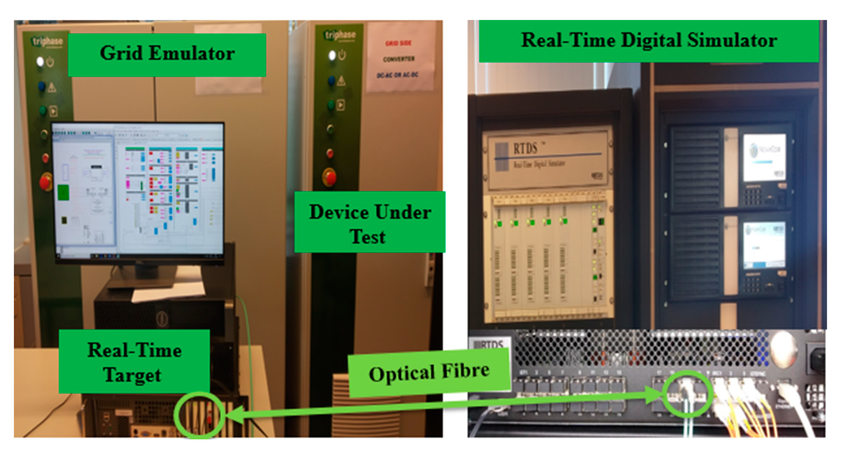
2.1. Conceptual Overview of the Proposed PHIL Setup

The proposed PHIL setup is illustratively represented in Figure 1. The setup involves the following components:
NovaCor chassis of the RTDS [20]: This is a high-performance multicore processor used for the modeling and real-time simulations of power electronic converted dominated power systems. Additionally, the Aurora protocol is applied to provide a communication interface between the chassis and the RTT, which are linked through a dedicated optical fiber.
Real-time target (RTT): This element constitutes a PC-based (multi-core) module working with a real-time operating system (e.g., Linux/Xenomai). It is used to enable the exchange of signals between the NovaCor chassis and the actual hardware used (i.e., for grid emulation and DUT). The studied FAPR control strategies are programmed in the RTT.
Grid Emulator: This component has a back-to-back layout, comprising a so-called front-end converter unit (to regulate the DC voltage) and a VSC unit that is used to create dynamic signals (i.e., time-varying waveforms of smaller amplitude) that resemble the simulated instantaneous waveforms (e.g., voltage, currents) obtained by using the NovaCor chassis.
DUT: This is a small-sized (15 kW) VSC which can represent the grid side converter of a decoupled (type-IV) WT. The FAPR is programmed in the RTT and acts on the DUT in real time. The inner and outer controllers of this DUT can be modified and tuned to resemble the generic models used in the NovaCor chassis. Therefore, this component is used in this paper to quantitatively corroborate the findings from pure software-based (RSCAD) simulation studies.

2.2. Working Principle of the PHIL Setup

Figure 2 depicts a descriptive figure of various terms and components involved in the proposed PHIL setup. The stepwise illustration of PHIL-based control strategy implementation and testing is performed as follows:
  • The real-time EMT representation of the studied system is performed in RSCAD [22] and runs in NovaCor, which can be interfaced with external physical devices (e.g., DUT).
  • The control strategies to subordinate the grid emulator and the DUT are implemented using the RTT. The implementation is done through a combined environment of Triphase (Triphase Technologies, Bangalore, India) and Matlab/Simulink (MathWorks, Natick, MA, USA). The RTT and NovaCor exchange signals (e.g., waveforms of voltages and currents) through an optical fiber.
  • The RTDS sends setpoints to RTT. These setpoints govern the instantaneous voltage of the grid emulator as well as the setpoints for the output current of the DUT.
  • The Aurora protocol is applied for the bidirectional transfer of information between RTDS and the RTT. The RTT has a circular inter-process communication (CIPC) buffer. The CIPC constitutes a distributed strategy for the sharing of memory through ring buffers. This facilitates the exchange of information of simulations from Matlab/Simulink control and signal processing models that are compiled in the RTT. Each buffer has a writer block that writes data into the buffer, from which multiple readers can read out the data. The Simulink model has blocks to perform write/read bus definitions. The bus definitions contain the names and sizes of the signals extracted from the read block. It should be ensured that the same bus name previously defined as the input/output bus name is used in the write/read blocks. In this way, 256 signals can be exchanged between the RTT and the RTDS.
  • The simulated instantaneous voltage from the system model running in RSCAD-RTDS is given to the RTT to reproduce the desired voltage waveform (with the same frequency but with smaller amplitude) at the AC side (i.e., the point of interconnection of the DUT) of the VSC of the grid emulator.
  • Since the RTDS and the RTT run simultaneously in real time, there exists the freedom to choose RSCAD or Simulink to implement each of the selected FAPR strategies. The current reference signals are affected by the implemented FAPR strategies. The VSC (DUT), which is connected to grid emulator with virtual PCC conditions injects active power based on the modulated active current reference (Id_ref).

3. Description of FAPR Control Strategies under Study

The selected FAPR control strategies are briefly presented in this section. Among the selected strategies are the:
  • Droop-based FAPR strategy
  • Droop-derivative-based FAPR strategy
  • VSP-based FAPR strategy

3.1. Droop-Based FAPR Strategy

Figure 3 shows the droop-based FAPR’s scheme. The input f constitutes the measured signal of time-varying frequency at a point of interface between the power plant and the system. Figure 1 illustrates that this signal can be obtained through a phasor measurement unit (PMU). The PMU is used to measure the frequency; it is taken from the RSCAD library. The PMU block is composed of a low-pass filter, sampling circuit, time-synchronized signal, and processing unit. Before processing the input signal for the estimation of its phasor value, it is filtered and sampled to overcome the problem of aliasing. It uses the FFT algorithm for its phasor estimation. The estimated phasor value consists of the magnitude, phase, frequency, and rate of change of frequency of its input signal. The instantaneous value of f is continuously contrasted with a fixed setpoint (e.g., with 50 Hz taken as the reference frequency fref). Next, the resulting error (Δf) is fed to a control loop that comprises a dead band and a gain (Kp). Both elements are tuned based on system-dependent dynamic properties.
The signal Δf is amplified by Kp. The output signal ΔPref of FAPR is a supplementary signal attached to the other active power control loop of a grid side converter. ΔPre performs exclusively when an active power imbalance occurs in the system. The drawback of the droop-based FAPR strategy resides in the slow initial response, which could be attributed to low frequency error values.

3.2. The Droop-Derivative Based FAPR Strategy

Figure 4 overviews the FAPR based on a droop-derivative hybrid control approach. The setpoint fref and the signals f and Δf are obtained as indicated in Section 3.1. Δf is passed through 2 parallel control loops: The first is a droop controller, which is described in the previous section. The actuation of the droop controller is active for the entire frequency curtailment period. The second loop is a derivative control, whose output is a derivative gain of the frequency error signal. The derivative controller is active only for the initial few seconds and lasts until the frequency signal reaches the maximum allowed frequency deviation. The combined effect of the outputs of the droop-based loop and derivative-based loop produces ΔPref, which modulates the active power response of the WT to improve both the RoCoF and maximum frequency deviation (e.g., the nadir).
The droop derivative FAPR strategy should be tuned (taking into account system-dependent dynamic properties) to cause a prominent ramping of the active power output at the AC side of a grid side converter whenever an over/under-frequency event occurs. The parameters of the droop control loop are described in Section 3.1. The parameters of the derivative control loop are shown in Figure 2, and involve the sequential reaction of a LPF (low-pass filter), a washout filter, and another gain factor (Kd).

3.3. The Virtual Synchronous Power (VSP)-Based FAPR Control Strategy

Figure 5 depicts the VSP controller, which measures the power required at the PCC to the reference power available at the bus. In this control scheme ζ is a damping coefficient, and ωn constitutes the natural frequency for implementing this second-order function.
As shown in Figure 6, the power going out from the node bus (P_bus) reacts to the grid when there is a load disturbance, whereas P_wt will not be instantaneously altered. This difference will be taken as error, ΔP, in the VSP control block (cf., Figure 5), which is further passed through a dead-band block, and later through a second-order transfer function. The output of this block defines the duty cycle of a PWM controller. Hence, the limits of this block are between 0 and 0.9.
Figure 7 describes the connection diagram of a battery power management system (BPMS), which has a battery energy storage system (BESS), and a DC-DC converter that operates bi-directionally. The BESS is integrated to the DC link of VSC converter through the DC-DC converter. The main function of the BPMS is to appropriately discharge the battery as per the pulse generated from the VSP control block. The state of the battery charge is not relevant to this study, and will be addressed in a future publication. The storage is used to inject active power to emulate the inertia. It has been assumed that during the activation of FAPR control, the battery is fully charged. The function of machine side converter is to convert the variable AC power generated by the wind turbine into the DC power. It also tracks the maximum power point of wind-generated power.

4. Experimental Testing of FAPR Control Strategies through PHIL

The widely used IEEE 9-bus system is modified by reducing the share of synchronous generation and increasing the wind power share. A total of 52% generation is contributed by renewable energy sources (RES), as depicted in Figure 8. Further, full-scale Type-4 WT models with functional switching converters are used. The type-IV wind generators interfaced with the back-to- back voltage source converters (VSCs) are the most commonly employed configuration of the wind power plant. The type-IV model is taken as a representative form of generation technology due to the advantages that this technology introduces, e.g., better low voltage ride-through (LVRT) capabilities, full-speed ratio control, absence of gear box, etc. Additionally, as to be presented, control modifications are performed in the grid-side voltage source converter (VSC). The developed test setup is generic for the testing of other converter control strategies reported in the literature. It is also applicable to other types of power electronic-interfaced wind turbines. This aids in understanding the impact of additional active power extraction in the frequency containment stage. Please note that the emulation of the mechanical part and most of the electrical parts of the WT model is developed in RSCAD, whereas the DUT converter emulates the electrical characteristics of the gird side converter of the full-scale type-IV WT. Table 1 presents the steady-state profile before the occurrence of an active power imbalance in the developed and simulated variant of the IEEE 9 bus system with 52% wind share. The total level of inertia is reduced because of the decommissioning of conventional plants with synchronous generators.
To test the FAPR control strategies, a generation–load imbalance had to be created. More specifically, an under-frequency event was created. To this aim, a sudden load was created at bus 8. After testing the impact of load frequency variations at various busses, it was found that the load generation imbalance at bus 8 had a greater impact on buses 2 and 3, where the type-IV wind power plant was connected. A 5% increase in load can be considered to present a large load generation imbalance for the study of frequency stability in the selected test system. Besides, it is assumed that the FAPR strategy performs within 10 s [7].
The parameters of the FAPR controllers were tuned by performing the sensitivity analysis illustrated in Figure 9. The value of these parameters depends on the level of renewable power penetration, the amount of active power to be injected, and the dynamic (time) evolution of RoCoF and the nadir of the measured frequency response(s). The following parameters were obtained: the dead-band of frequency was 2% for all FAPR strategies; Kp = 1.5 for droop-based FAPR (cf. Figure 3); Kp = 1.9, Kd = 0.4, G = 8 × 10⁵, Fcut-off = 0.5 Hz (lead-lag filter), and Tw = 1 × 10⁻⁵ s (washout filter) for the droop-derivative-based FAPR (cf. Figure 4); and Kv = 1.25, ζ = 0.35, and ωn = 70.71Hz for VSP-based FAPR (cf. Figure 5).
Figure 10 shows the response the system’s generators and the resulting frequency dynamics. Note in Figure 10 that the injection of active power by the wind generators remains constant because of the absence of the FAPR strategy. In order to test the FAPR control strategies, the following steps were performed using the proposed PHIL setup (cf. Figure 11):
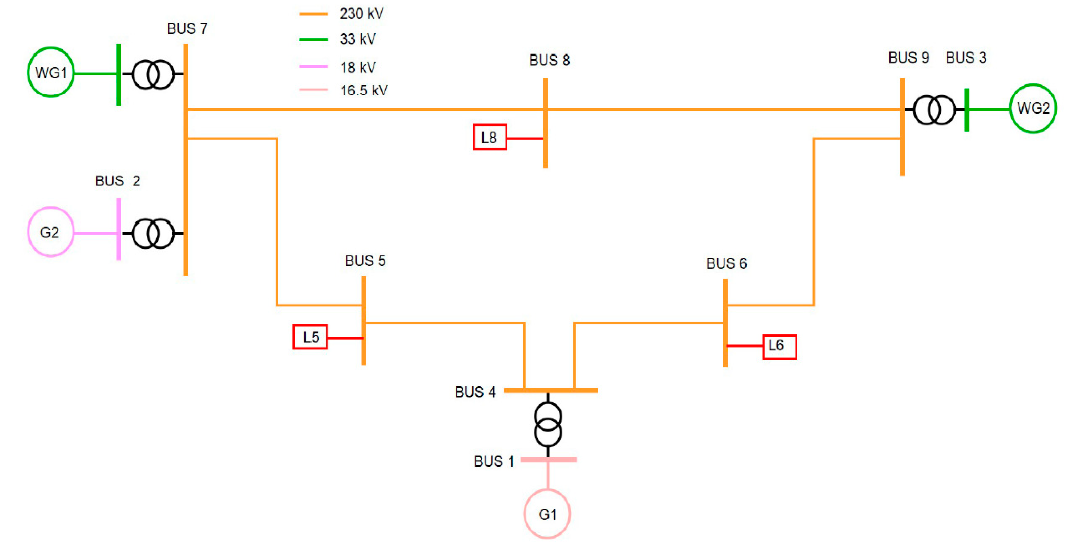
  • The RTDS Nova Core was used to compile and run the system under study (cf. Figure 8).
  • The time-varying samples of voltage and frequency (e.g., measured at bus 7 in Figure 8) were transferred from RTDS to the RTT by using the Aurora protocol. These voltage and frequency values were taken as a reference to create the voltage waveform of the grid emulator, which is connected to the AC side of the DUT.
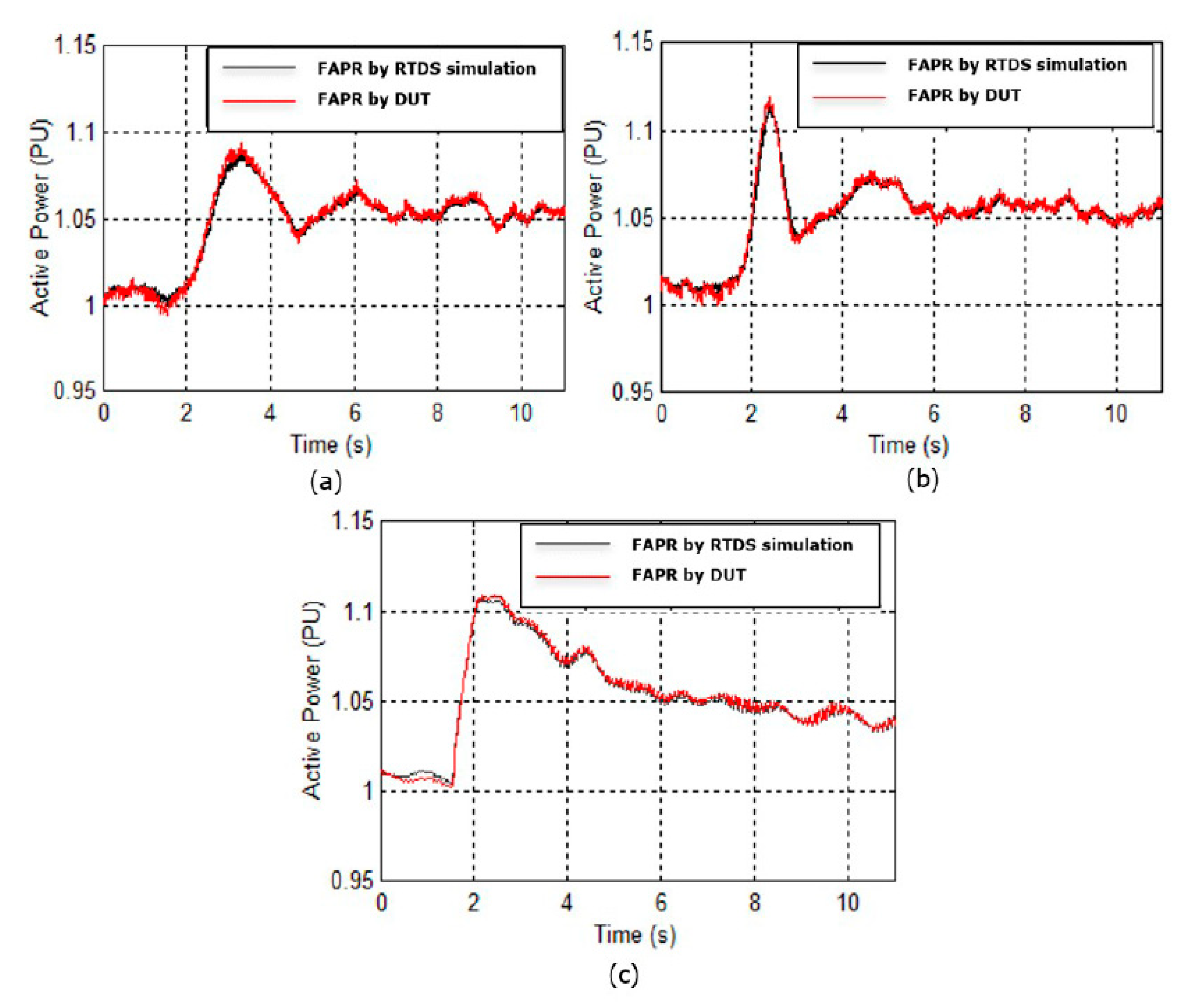
  • The active power and reactive power at the AC side of the DUT were controlled by Id_ref and Iq_ref.
Figure 12a—shows the active power injections influenced by the FAPR strategies (i.e., droop, droop-derivative, or VSP). The active output power of the mockup VSC (i.e., DUT) highly resembles the pure EMT simulation-based study (through RTDS simulations). The obtained PHIL results validate the simulation results and the RTDS EMT model.
The time-varying injections of active power by the selected FAPR control strategies and their implications for dynamic frequency performance are plotted in Figure 13 and Figure 14, respectively. The degree of improvement in frequency dynamics depends on the speed of adjustment and the amount of power injected into the grid. The droop derivative-based FAPR’s power injection rise time was less than that of the only droop-based control strategy. Hence, the former was more effective in improving both the nadir and frequency slope before the nadir than the latter. Unlike the droop and droop derivative-based FAPR control strategies, the VSP-based FAPR-based control strategy was independent of frequency measurement. Hence, the response of VSP-based FAPR was faster and exhibited lower rise time of the WT’s time-varying active power injection (cf., Figure 13). Therefore, the impact of the VSP-based FAPR on frequency dynamics improvement was noticeably better than the impact of droop-based FAPR and derivative-based FAPR, as shown in Figure 14.
Figure 15 and Figure 16 illustrate the response of WG1 equipped with droop-derivative-based FAPR, taking into account the condition of wind energy extraction above the nominal power during an under-frequency event. Figure 15 corresponds to the variation of the electrical power output due the activation and deactivation of the droop derivative-based FAPR. The small figure inside Figure 15 illustrates the variation of the output signal of the droop derivative-based FAPR. Figure 16 corresponds to the variation of mechanical power over time (considered as an indication of the variation of the stored mechanical energy).
It is worth pointing out that the duration of droop derivative-based FAPR was assumed to be 10 s. From Figure 15 and Figure 16 it can be seen that droop-derivative-based FAPR caused a temporary increase (lasting around 2 s) in the output power of WG1 of up to 30% above its nominal output power (needed for effective frequency support). Next, the threshold for active power adjustment by droop derivative-based FAPR was reduced (cf., small figure inside Figure 15) such that the frequency support can last for 8–10 s, during which synchronous generation should be able to perform primary frequency control. Note also that the mechanical power (and also the kinetic energy) decreased at a constant rate after the activation of droop-derivative-based FAPR, causing a continuous reduction in the output power of WG1. Once the droop derivative-based FAPR was deactivated (around t = 16 s) the mechanical power started to recover, in line with the load-generation curve of WG1.

5. Conclusions

This paper presents a study based on EMT real-time simulations and a proposed PHIL test setup for the testing of mitigation measures for frequency stability. The emphasis was on FAPR control strategies attached to the VSC unit that interfaced a type-IV WT with a power system. The use of local storage (i.e., taking electrical batteries as an example) was one assumption motivated by several studies from the current state of the art. Other alternatives (e.g., those more convenient from a techno-economic point of view) are currently being explored and will be reported in a subsequent article. For the studied system (with a variant of the IEEE 9 bus system with 52% supply from wind power plants), by performing EMT simulations and PHIL testing of FAPR with RSCAD, it was observed that fast active power injection (lower rise time) and the amount of available energy were the two key factors influencing the effectiveness of a FAPR controllers. The rise time of the droop derivative-based FAPR’s power injection was less than that observed in the case of the droop-based FAPR control strategy. Hence, the former was more effective in improving both the nadir and frequency slope before nadir than the latter. Unlike the droop and the droop derivative-based FAPR controller, the VSP-based controller was independent of the frequency measurement. Besides, its response was faster and exhibited a lower rise time of active power injection. As a result, its impact on frequency dynamics improvement was better than that of the droop controller and the droop derivative control strategies. The main merits of the VSP-based FAPR control strategy are its simple practical implementation and frequency measurement-independent characteristics. Hence, it can be considered as the most suitable candidate for fast active power frequency control. Future research will be devoted to the extension of the setup to consider other possible sources for fast active power frequency control (e.g., electrolyzers, solar photovoltaic systems). Furthermore, the development and testing of other controllers that can be attached to power electronic-interfaced devices to support other primary control functions (e.g., oscillation damping) will be carried out.

Author Contributions

Conceptualization, J.R.T., Z.A., N.V.K.; formal analysis, J.R.T., Z.A., N.V.K.; investigation, Z.A., N.V.K., J.R.T.; methodology, Z.A., N.V.K., J.R.T. and E.R.; resources, Z.A., N.V.K., J.R.T., E.A.; software, J.R.T., Z.A., N.V.K.; supervision, J.R.T., E.R., E.A., P.P., and M.v.d.M.; validation, J.R.T., Z.A., N.V.K.; visualization, J.R.T., Z.A. and N.V.K.; writing—original draft, Z.A., N.V.K., J.R.T.; writing—review and editing, Z.A., N.V.K., J.R.T., E.R., P.P. and M.v.d.M. All authors have read and agreed to the published version of the manuscript.

Funding

This research was carried out as part of the MIGRATE project. This project has received funding from the European Union’s Horizon 2020 research and innovation program, under grant agreement no. 691800. This reflects only the authors’ views, and the European Commission is not responsible for any use that may be made of the information it contains.

Institutional Review Board Statement

Not applicable.

Informed Consent Statement

Not applicable.

Data Availability Statement

Not applicable.

Acknowledgments

This research was carried out as part of the MIGRATE.

Conflicts of Interest

The authors declare no conflict of interest. The funders had no role in the design of the study; in the collection, analyses, or interpretation of data; in the writing of the manuscript, or in the decision to publish the results.

References

  1. Blaabjerg, F.; Ma, K. Future on power electronics for wind turbine systems. IEEE J. Emerg. Sel. Top. Power Electron. 2013, 1, 139–152. [Google Scholar] [CrossRef]
  2. Chen, Z.; Guerrero, J.M.; Blaabjerg, F. A review of the state of the art of power electronics for wind turbines. IEEE Trans. Power Electron. 2009, 24, 1859–1875. [Google Scholar] [CrossRef]
  3. Blaabjerg, F.; Ma, K. Power electronics converters for wind turbine systems. IEEE Trans. Ind. Appl. 2012, 48, 708–719. [Google Scholar] [CrossRef] [Green Version]
  4. Dreidy, M.; Mokhlis, H.; Mekhilef, S. Inertia response and frequency control techniques for renewable energy sources: A review. Renew. Sustain. Energy Rev. 2017, 69, 144–155. [Google Scholar] [CrossRef]
  5. Ha, F.; Abdennour, A. Optimal use of kinetic energy for the inertial support from variable speed wind turbines. Renew. Energy 2015, 80, 629–643. [Google Scholar]
  6. Mishra, S.; Zarina, P.P. A Novel Controller for Frequency Regulation in a Hybrid System with High PV Penetration. In Proceedings of the 2013 IEEE Power & Energy Society General Meeting, Vancouver, BC, Canada, 21–25 July 2013; pp. 1–5. [Google Scholar]
  7. Josephine, R.L.; Suja, S. Estimating PMSG Wind Turbines by Inertia and Droop Control Schemes with Intelligent Fuzzy Controller in Indian Development. Electr. Eng. Technol. 2014, 9, 1196–1201. [Google Scholar] [CrossRef] [Green Version]
  8. Yao, W.; Lee, K.Y. A Control Configuration of Wind Farm for Load-following and Frequency Support by Considering the Inertia Issue. In Proceedings of the 2011 IEEE Power and Energy Society General Meeting, San Diego, CA, USA, 24–28 July 2011; pp. 1–6. [Google Scholar]
  9. Engelken, S.; Mendonca, A.; Fischer, M. Inertial response with improved variable recovery behaviour provided by type 4 WTs. IET Renew. Power Gener. Spec. 2017, 11, 195–201. [Google Scholar] [CrossRef]
  10. Rakhshani, E.; Rodriguez, P. Inertia Emulation in AC/DC Interconnected Power. IEEE Trans. POWER Syst. 2017, 32, 3338–3351. [Google Scholar] [CrossRef]
  11. Gonzalez-Longatt, F.; Chikuni, E.; Rashayi, E. Effects of the Synthetic Inertia from Wind Power on the Total System Inertia after a Frequency Disturbance. In Proceedings of the 2013 IEEE International Conference on Industrial Technology (ICIT), Cape Town, South Africa, 25–28 February 2013; pp. 826–832. [Google Scholar]
  12. Ackermann, T. Wind Power in Power Systems, 2nd ed.; Wiley: Hoboken, NJ, USA, 2005; Volume 140. [Google Scholar]
  13. Rakhshani, E.; Remon, D.; Cantarellas, A.M.; Rodriguez, P. Analysis of derivative control based virtual inertia in multi-area high-voltage direct current interconnected power systems. IET Gener. Transmiss. Distrib. 2016, 10, 1458–1469. [Google Scholar] [CrossRef] [Green Version]
  14. Rakhshani, E.; Remon, D.; Cantarellas, A.M.; Garcia, J.M.; Rodriguez, P. Virtual Synchronous Power Strategy for Multiple Power Systems. IEEE Trans. Power Syst. 2017, 32, 1665–1677. [Google Scholar] [CrossRef]
  15. Beck, H.-P.; Hesse, R. Virtual synchronous machine. In Proceedings of the 9th EPQU, Barcelona, Spain, 9–11 October 2007; pp. 1–6. [Google Scholar]
  16. Driesen, J.; Visscher, K. Virtual synchronous generators. In Proceedings of the IEEE PESGM, Pittsburgh, PA, USA, 20–24 July 2008; pp. 1–3. [Google Scholar]
  17. Zhong, Q.; Weiss, G. Synchronverters: Inverters that mimic synchronous generators. IEEE Trans. Ind. Electron. 2011, 58, 1259–1267. [Google Scholar] [CrossRef]
  18. Yan, X.; Mohamed, S.Y.A. Comparison of virtual synchronous generators dynamic responses. In Proceedings of the 2018 IEEE 12th International Conference on Compatibility, Power Electronics and Power Engineering (CPE-POWERENG 2018), Doha, Qatar, 10–12 April 2018; pp. 1–6. [Google Scholar]
  19. Soni, N.; Doolla, S.; Chandorkar, M.C. Improvement of transient response in microgrids using virtual inertia. IEEE Trans. Power Deliv. 2013, 28, 1830–1838. [Google Scholar] [CrossRef]
  20. RTDS Technologies Inc. The Simulator-Hardware. Available online: https://www.rtds.com/thesimulator/our-hardware (accessed on 3 February 2021).
  21. RTDS Technologies Inc., RSCAD Modules. Available online: https://www.rtds.com/thesimulator/our-software/rscad-modules (accessed on 3 February 2021).
  22. Fang, J.; Li, H.; Tang, Y.; Blaabjerg, F. On the Inertia of Future More-Electronics Power Systems. IEEE J. Emerg. Sel. Top. Power Electron. 2019, 7, 2130–2146. [Google Scholar] [CrossRef]
  23. Veerakumar, N.; Ahmad, Z.; Adabi, M.E.; Torres, J.R.; Palensky, P.; van der Meijden, M.; Gonzalez-Longatt, F. Fast Active Power-Frequency Support Methods by Large Scale Electrolyzers for Multi-Energy Systems. In Proceedings of the 2020 IEEE PES Innovative Smart Grid Technologies Europe (ISGT-Europe), The Hague, The Netherlands, 26–28 October 2020; pp. 151–155. [Google Scholar] [CrossRef]
  24. Rakhshani, E.; Perilla, A.; Veerakumar, N.; Ahmad, Z.; Rueda Torres, J.; van der Meijden, M.; Palensky, P. Analysis and tuning methodology of FAPI controllers for maximising the share of grid-connected wind generations. IET Renew. Power Gener. 2020, 14, 3816–3823. [Google Scholar] [CrossRef]
  25. Rakhshani, E.; Remon, D.; Cantarellas, A.M.; Garcia, J.M.; Rodriguez, P. Modeling and sensitivity analyses of VSP based virtual inertia controller in HVDC links of interconnected power systems. Electr. Power Syst. Res. 2016, 141, 246–263. [Google Scholar] [CrossRef]
  26. Gonzalez-Longatt, F.M.; Bonfiglio, A.; Procopio, R.; Verduci, B. Evaluation of inertial response controllers for full-rated power converter wind turbine (Type 4). In Proceedings of the 2016 IEEE Power and Energy Society General Meeting (PESGM), Boston, MA, USA, 17–18 July 2016; pp. 1–5. [Google Scholar]
  27. International Review of Frequency Control Adaptation, Australia Energy Market Operator. Melbourne, VIC, Australia. 2017. Available online: http://www.aemo.com.au (accessed on 3 February 2021).
  28. Tolbert, L.M.; Wang, F.; Tomsovic, K.; Sun, K.; Wang, J.; MA, Y.; LIU, Y. Reconfigurable Real-Time Power Grid Emulator for Systems with High Penetration of Renewables. IEEE Open Access J. Power Energy 2020, 7, 489–500. [Google Scholar] [CrossRef]
  29. Ahmad, Z.; Torres, J.R.; Veera Kumar, N.; Rakhshani, E.; Palensky, P.; van der Meijden, M. A Power Hardware-in-the-Loop Based Method for FAPR Compliance Testing of the Wind Turbine Converters Control. Energies 2020, 13, 5203. [Google Scholar] [CrossRef]
  30. Cha, S.T.; Wu, Q.; Nielsen, A.H.; Østergaard, J.; Park, I.K. Real-Time Hardware-In-The-Loop (HIL) Testing for Power Electronics Controllers. In Proceedings of the 2012 Asia-Pacific Power and Energy Engineering Conference, Shanghai, China, 27–29 March 2012; pp. 1–6. [Google Scholar]
  31. Ahmad, Z.; Papadakis, S.; Perilla, A.; Torres, J.R.; Meijden, M.v.d. Hardware-in-the-loop based testing of wind turbine controllers for transient stability enhancement. In Proceedings of the 2020 IEEE 29th International Symposium on Industrial Electronics (ISIE), Delft, The Netherlands, 17–19 June 2020; pp. 1244–1249. [Google Scholar]
  32. Park, I.K.; Forsyth, P.; Kuffel, R.; Tara, E. Hardware in the loop (HILS) testing of a power electronics controller with RTDS. In Proceedings of the IECON 2013—39th Annual Conference of the IEEE Industrial Electronics Society, Vienna, Austria, 10–13 November 2013; pp. 5386–5391. [Google Scholar]
  33. Fingrid—Technical Requirements for Fast Frequency Reserve Have Been Published. Electric Energy Online, Niklas Modig (Lead Editor), Robert Eriksson; Svenska Kraftnät Liisa Haarla, Pia Ruokolainen, Mikko Kuivaniemi; Fingrid Knut Styve Hornnes, Per Arne Vada; Statnett Soroush Afkhami Meybodi; Energinet Daniel Karlsson; DNV GL, 4 July 2019. Available online: Electricenergyonline.com/article/energy/category/t-d/56/778092/technical-requirements-for-fast-frequency-reserve-have-been-published.html (accessed on 3 February 2021).
  34. Nikolopoulou, A. Wind Turbine Contribution to Ancillary Services under Increased Renewable Penetration levels. Master’s Thesis, Delft University of Technology, Delft, The Netherlands, 2017. Available online: https://repository.tudelft.nl/islandora/object/uuid%3A321a3ff0-5c7a-4c33-a891-4f0233c32ac9 (accessed on 3 February 2021).
  35. Oak Ridge National Laboratory. Frequency Control Concerns in the North American Electric Power System. Available online: https://info.ornl.gov/sites/publications/Files/Pub57419.pdf (accessed on 3 October 2020).
Figure 1. Developed PHIL setup.
Energies 14 03274 g001
Figure 2. Interactions between the components of the PHIL setup.
Energies 14 03274 g002
Figure 3. The droop-based FAPR controller block diagram.
Energies 14 03274 g003
Figure 4. Block diagram of the droop derivative-based FAPR strategy.
Energies 14 03274 g004
Figure 5. Block diagram of a VSP-based FAPR control strategy.
Energies 14 03274 g005
Figure 6. Connection of a decoupled WT to the system, indicating the inputs for VSP-based FAPR.
Energies 14 03274 g006
Figure 7. Circuit diagram of a VSP-based BPMS.
Energies 14 03274 g007
Figure 8. Used variant of the IEEE 9 bus test system, taking into account 52% supply from wind power generation.
Energies 14 03274 g008
Figure 9. Procedure for parametric sensitivity-based tuning of FAPR.
Energies 14 03274 g009
Figure 10. EMT simulations performed in RTDS (i.e., without FAPR, no use of PHIL). Response of wind and synchronous generators and their impact on frequency dynamics.
Energies 14 03274 g010
Figure 11. Use of the PHIL setup for the evaluation of FAPR strategies.
Energies 14 03274 g011
Figure 12. FAPR by simulated and DUT converters (a) with a droop controller; (b) with a derivative-based controller; and (c) with a VSP-based controller.
Energies 14 03274 g012
Figure 13. Comparison among FAPR controllers.
Energies 14 03274 g013
Figure 14. Dynamics of frequency due to FAPR controllers.
Energies 14 03274 g014
Figure 15. Response of WG1 during the extraction of kinetic energy: Variation of electrical output power.
Energies 14 03274 g015
Figure 16. Response of WG1 during the extraction of kinetic energy: Variation of mechanical power.
Energies 14 03274 g016
Table 1. Steady-state profile before the occurrence of an active power imbalance.
ComponentG1G2WG1WG2L5L6L8
MW73.478.282.68412590100
MVAr33.8−1.800503035
Publisher’s Note: MDPI stays neutral with regard to jurisdictional claims in published maps and institutional affiliations.

