Article

Synchronization of N-Non-Linear Slave Systems with Master System Using Non-Adaptive and Adaptive Coupled Observers

by
Ghayyur Hussain
1,*,
Muhammad Siddique
1,
Muhammad Majid Hussain
2,
Muhammad Tahir Hassan
3 and
Naeem Aslam
1
1
Department of Electrical Engineering & Computer Science, NFC Institute of Engineering and Technology, Multan 66000, Pakistan
2
Department of Electrical and Electronic Engineering, University of South Wales, Pontypirdd CF37 1DL, UK
3
Department of Mechanical Engineering, Bahauddn Zakariya University, Multan 66000, Pakistan
*
Author to whom correspondence should be addressed.
Energies 2021, 14(11), 3190; https://doi.org/10.3390/en14113190
Submission received: 28 April 2021 / Revised: 23 May 2021 / Accepted: 26 May 2021 / Published: 29 May 2021

Abstract

:
Synchronization of N-slave chaotic systems with a master system is a challenging task, particularly in recent times. In this paper, a novel methodology is proposed for synchronizing the N number of slave systems with a master system. The proposed methodology is based on coupled adaptive synchronous observers. The difference between the corresponding states of master and slave systems is converged to the origin by means of a novel feedback control scheme to achieve synchronization between the master and slave systems. The efficacy of the proposed methodology is verified through a simulation of FitzHugh–Nagumo non-linear systems in MATLAB. The simulation results validate and prove claims, and these systems are successfully synchronized by CCS and CCAS observer-based control.

1. Introduction

Synchronization of non-linear systems is crucially important to real-life systems. As a result of this importance, many researchers have explored a variety of methodologies for the synchronization of master–slave architectures. This master–slave architecture might be of a different type. Of these many types, single master with single slave and single master with multiple slave agents are the two architectures that exist most commonly in nature. The literature review reveals synchronizing control methodologies for the single master and single slave architecture. However, control methodologies for single master with multiple slave systems are largely absent from the literature. This scarcity is acute in the case of non-linear systems. Nonetheless, the seminal work of Grebogi, Ottand, and York [1] on the control of chaotic systems was studied in [2,3]. Synchronization of chaotic systems by means of different techniques of feedback control was elaborated upon in [4] and its application for secure communication was presented in [5]. In fractional-order systems, much effort has been devoted to the control and stability of synchronization in recent years [6,7].
In practical systems, there are some unidentified factors. For example, chaos, uncertainty, and disturbance change the results of system stability and synchronization, as identified in [8,9]. Additionally, model uncertainties are important. Model uncertainty is due to imperfections in and assumptions made about systems. The communication links between the systems can also affect the control methodology for synchronization. For example, in distributed power systems, communication delays can deteriorate the performance of the systems. We must consider the presence of all these factors for better performance and synchronization. Edward Ott [1] is a scientist who played a substantial part in the theory of chaos. This theory can be used in numerous natural and artificial systems. Chaos is a non-linear long-time oscillatory aperiodic behavior with a sensitive response to initial conditions [10].
Master and slave systems are synchronized if the error between the driven and driving systems becomes zero [11,12]. The first successful effort to synchronize chaotic systems with non-similar initial conditions was made by Carroll and Pecora in their research paper [13]. After this work, researchers worked hard on the synchronization of chaotic systems, introducing different techniques. Different techniques, such as evolutionary algorithms [14], adaptive generalized projective synchronization (GPS) [15], the observer-based step-by-step sliding mode technique [16], robust adaptive methodologies [17,18], back-stepping techniques [19], an adaptive scheme using fuzzy uncertain disturbance observers [20], delay range-dependent practices [21,22], synchronization through Huygens’ coupling [23], non-linear observer Runge–Kutta’s model [24], full order and reduced order output-affine observers [25], linear feedback control [26], and the unknown input of Takagi–Sugeno’s fuzzy chaotic systems, synchronized in [12]. These techniques for chaotic system synchronization are valuable in different types of application, such as biological systems [27], secure communication [16,17,18,19,20,21,22,23,24,25,26,27,28], robotics [29], neural networks [30], lasers and optics [31], chemical reactions [32], and info science [33].
Synchronizing techniques based on observers are more applicable in conditions in which all the states of the driver and slave systems are unknown [34,35]. Similarly, other observer-based synchronizing control schemes are general projective synchronization methods based on state estimation of hyper-chaotic systems [15] and step-by-step sliding mode observers [17]. Similarly, the adaptive observer-based synchronization of two dissimilar chaotic systems with different initial conditions and parameters is elaborated upon in [36]. Chaotic systems are synchronized using a robust adaptive control technique in [21]. Takagi–Sugeno’s fuzzy systems are synchronized by means of an observer-based technique and are helpful for secure communication [28]. Hyper-chaotic system synchronization based on observers is discussed in [37]. Different methods of observer-based synchronization, as discussed above, are not capable of dealing with the synchronization of non-linear systems in a single master and multi-slave architecture.
In this paper, the main contribution is the synchronization of N-non-linear systems with single master systems, which is established by developing a control methodology based on special types of observer. Multiple complex chaotic systems can be synchronized with the single master system by the proposed control methodology. The observers used in this scheme are known as coupled chaotic synchronous (CCS) observers and coupled chaotic adaptive synchronous (CCAS) observers [38]. By using these observers, an effective control scheme is developed for the convergence of error (the difference between the corresponding states of master systems and the estimated states of slave systems) to the origin for complete synchronization of the master–slave network. We can achieve synchronization between non-linear master and slave systems using these observers.
This paper is arranged in sections. Section 2 describes the system structure with some considerations. Section 3 elaborates upon the non-linear observer-based synchronization control scheme. Simulation results for synchronization of neurons are presented in Section 4, while Section 5 sets out the conclusion of the article.

2. System Description

The state–space representations of master and N-slave chaotic systems are given below.
x ˙ m ( t ) = A x m ( t ) + f ( x m ( t ) ) , y m ( t ) = C x m ( t ) ,
x ˙ s 1 ( t ) = A x s 1 ( t ) + f ( x s 1 ( t ) ) + B u 1 ( t ) , y s 1 ( t ) = C x s 1 ( t ) , x ˙ s 2 ( t ) = A x s 2 ( t ) + f ( x s 2 ( t ) ) + B u 2 ( t ) , y s 2 ( t ) = C x s 2 ( t ) , x ˙ s i ( t ) = A x s i ( t ) + f ( x s i ( t ) ) + B u i ( t ) , y s i ( t ) = C x s i ( t ) ,       i = 1 , 2 , 3 , n }
In the master and slave system, the state vectors are x m ( t ) R n and x s i ( t ) R n , respectively. Similarly, the output vectors are y m ( t ) R m and y s i ( t ) R m , and the real constant matrices are A R n × n , B R n × l , and C R m × n . The non-linearities of the master and N-slave systems are represented by F ( x ( t ) ) R n , which are the vector functions of the non-linear systems. The control input is u i ( t ) R l . Non-linearity plays a crucial role in the dynamics of the systems. Systems can become unstable or unpredictable due to these non-linearities. Therefore, synchronization of non-linear systems is a tedious task. To make it possible to synchronize the completed non-linear system, a control scheme is presented in this paper. This control scheme caters to the effect of the non-linearities in the models of the non-linear system in non-adaptive cases. Additionally, adaptation laws are used for the adaptation of unknown parameters.
Assumption 1.
Non-linearity in the leading system and the N-slave system, i.e., F ( x ( t ) ) satisfies the Lipchitz condition, which is given below:
f ( x s ( t ) ) f ( x ¯ s ( t ) ) L f x s ( t ) x ¯ s ( t ) , x s ( t ) , x ¯ s ( t ) R n
Here, the constant matrices are L f > 0 . Therefore, the states of the systems are often not available in many real-world scenarios, meaning that the states of the master and multi-slave systems, (1) and (2), are estimated by their respective observers, and the different initial states are used to examine synchronization by feedback control for synchronization. The control signal is of the form:
u ( t ) = ξ ( x ^ m ( t ) , x ^ s i ( t ) ) ,
It is known that x m ( t ) and x s i ( t ) are estimated as x ^ m ( t ) R n and x ^ s i ( t ) R n , respectively. This control function (4) is based on estimated states, calculated by respective observers of the master and slave systems. A suitable methodology has been developed for control and synchronization of the master and N-slave systems (1) and (2) from its initial position. Within this methodology, first of all, the dynamics of errors between the corresponding states of the master and N-slave systems and their observers are calculated. The error dynamics are then converged to the origin for complete synchronization of the systems using the proposed control scheme.

3. Observer-Based Synchronization

The vector function ξ ( x ^ m ( t ) , x ^ s i ( t ) ) in the proposed controller is selected as
ξ ( x ^ m ( t ) , x ^ s i ( t ) ) = F ( x ^ m ( t ) x ^ s i ( t ) )
The controller gain matrix is F R l × n . Specially designed observers, as elaborated upon in Equations (5) and (6), are selected to estimate the states of both the master and N-slave systems. Non-linear observers of the master and N-slave systems are given below as:
x ^ ˙ m ( t ) = A x ^ m ( t ) + L m ( y m ( t ) y ^ m ( t ) ) + f ( x ^ m ( t ) ) 1 2 B F ( x ^ m ( t ) x ^ s i ( t ) ) , y ^ m ( t ) = C x ^ m ( t )
x ^ ˙ s i ( t ) = A x ^ s i ( t ) + L s i ( y s i ( t ) y ^ s i ( t ) ) + f ( x ^ s i ( t ) ) 1 2 B F ( x ^ s i ( t ) x ^ m ( t ) ) , y ^ s i ( t ) = C x s i ( t ) ,
where i { 1 , 2 , 3 N } , L m R n × m , and L s i R n × m are the gain matrices of the observers. The errors are defined below:
e m ( t ) = x m ( t ) x ^ m ( t )
e s i ( t ) = x s i ( t ) x ^ s i ( t ) ,
e o i ( t ) = x ^ m ( t ) x ^ s i ( t ) , i = 1 , 2 , 3 , 4 , , n
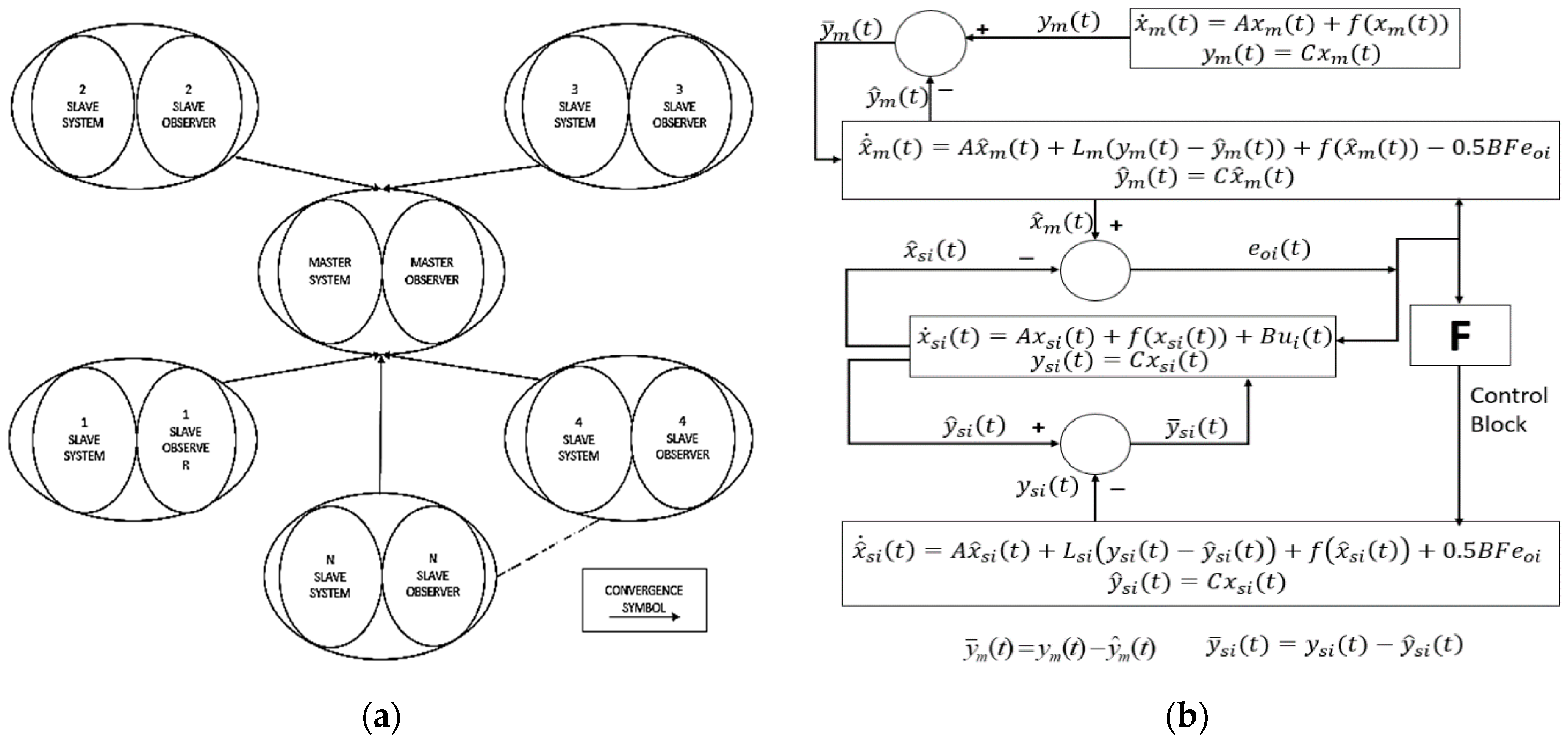
Different error signals, (8)–(10), have to be converged to zero by applying the control signal for synchronizing the master and slave systems. The convergence of the synchronizing error e o i ( t ) to the origin shows that the dynamics of the observers of all slaves coincide with observers of the master system. The convergence of error e s i ( t ) to the origin can be used to make sure that the estimated state x ^ s i ( t ) approaches the actual state x s i ( t ) . Similarly, by converging the errors e m ( t ) to the origin, we can make sure that x ^ m ( t ) —the estimated approach to the actual state—is x m ( t ) . The values of gain matrices L m , L s i , and F are assumed to be known, and these values are such that the proposed control methodology successfully converges the synchronization errors (8)–(10) to zero. Figure 1 representing the architecture of the master and N-slave systems.
Remark 1.
This paper has the simple idea that, by applying the observers, coherence of chaotic master and N-slave systems can be accomplished. All assumptions for imposed leading and N-response systems are the same. The estimated output error of synchronization—i.e., e o i ( t ) = x ^ m ( t ) x ^ s i ( t ) —reaches zero, meaning that all the observers synchronize with the observers of a master system. The observers are named as synchronous observers because they play a vital role in the synchronization process.
Remark 2.
The given observers, (6) and (7), are both very different from the usual Lune Berger observers due to the coupled terms 0.5 B F ( x ^ m ( t ) x ^ s i ( t ) ) and 0.5 B F ( x ^ s i ( t ) x ^ m ( t ) ) . For the specified values of F, the strong point of the coupling terms can be increased considerably so that these observers are synchronized. The projected observers are therefore called CCS observers. By using CCS observers, we will obtain the conditions for the synchronization of systems (1) and (2).
Theorem 1.
Focused on Assumption 1, there is a condition that is suitable for synchronizing the master and N-slave networks (1) and (2). It is obtained through the use of CCS observers (6) and (7) and also by using the control laws (4) and (5), which are only valid for the provided observer and controller gain matrices F R l × n , L m R n × m , and L s i R n × m . This condition is that there happens to be definite and positive symmetric matrices P m , Psi, and P o i of appropriate scalars— α 1 > 0 , α 2 > 0 , and α i > 0 are the dimensions that satisfy the matrix inequality.
Δ 1 = [ ρ 1 0.0 0.5 P m B F + C T L m T P o i P m 0.0 0.0 ρ 2 0.5 P s i B F C T L s i T P o i 0.0 P s i 0.0 ρ 3 0.0 0.0 P o i α 0 0.0 0.0 i = 1 n α i 0.0 i = 1 n α i + 1 ] < 0
whereas
ρ 1 = ( A T C T L m T ) P m + P m ( A L m C ) + α 0 L f 2 ,
ρ 2 = i = 1 n ( A T C T L s i T ) P s i + i = 1 n P s i ( A L s i C ) + i = 1 n α i L f 2 ,
ρ 3 = i = 1 n ( A T F T B T ) P o i + i = 1 n P o i ( A B F ) + i = 1 n α i + 1 L f 2
Let us consider the Lyapunov function below,
V ( t ) = e m T ( t ) P m e m ( t ) + e s i T ( t ) P s i e s i ( t ) + e o i T ( t ) P o i e o i ( t )
The Lyapunov function after time derivative is given as:
V · ( t ) = e ˙ m T ( t ) P m e m ( t ) + e m T ( t ) P m e ˙ m ( t ) + e ˙ s i T ( t ) P s i e s i ( t ) + e s i T ( t ) P s i e · s i ( t ) + e ˙ o i T ( t ) P o i e o i ( t ) + e o i T ( t ) P o i e ˙ o i ( t ) .
The time rate for change of error can be obtained through use of Equations (8)–(10). After some mathematical simplifications, the following result is obtained.
e ˙ m ( t ) = ( A L m C ) e m ( t ) + f ( x m ( t ) ) f ( x ^ m ( t ) ) + 1 2 B F e o i ( t ) e ˙ m ( t ) = ( A L m C ) e m ( t ) + Δ f m m ^ ( t ) + 1 2 B F e o i ( t )
e ˙ s i ( t ) = ( A L s i C ) e s i ( t ) + f ( x s i ( t ) ) f ( x ^ s i ( t ) ) + 1 2 B F e o i ( t ) e ˙ s i ( t ) = ( A L s i C ) e s i ( t ) + Δ f s s ^ ( t ) + 1 2 B F e o i ( t )
e ˙ o i ( t ) = ( A B F ) e o i ( t ) + f ( x ^ m ( t ) ) f ( x ^ s i ( t ) ) + L m C e m ( t ) L s i C e s i ( t ) e ˙ o i ( t ) = ( A B F ) e o i ( t ) + Δ f m ^ s ^ ( t ) + L m C e m ( t ) L s i C e s i ( t )
From Assumption 1, we can write the inequalities as follows:
α 0 [ Δ f m m ^ ( t ) ] T [ Δ f m m ^ ( t ) ] + α 0 L f 2 e m T ( t ) e m ( t ) > 0 ,
i = 1 n ( α i [ Δ f s s ^ ( t ) ] T [ Δ f s s ^ ( t ) ] ) + i = 1 n α i L f 2 e s i T ( t ) e s i ( t ) > 0 , i = 1 n ( α i [ Δ f m ^ s ^ ( t ) ] T [ Δ f m ^ s ^ ( t ) ] ) + i = 1 n α i L f 2 e o i T ( t ) e o i ( t ) > 0 .
By using the Lipschitz conditions, the scalars α 0 > 0 and α i > 0 are beneficial for the possibility of design constraints. By inputting (14)–(16) into (13), the final equation is achieved as set out below.
V ˙ ( t ) [ e m T ( t ) ( A T C T L m T ) + [ Δ f m m ^ ( t ) ] T + 0.5 e o i T ( t ) F T B T ] P m e m ( t ) + e m T ( t ) P m [ ( A L m C ) e m ( t ) + [ Δ f m m ^ ( t ) ] + 0.5 B F e o i ( t ) ] + i = 1 n ( [ e s i T ( t ) ( A T C T L s i T ) + [ Δ f s s ^ ( t ) ] T + 0.5 e o i T ( t ) F T B T ] P s i e s i ( t ) + e s i T ( t ) P s i ( ( A L s i C ) e s i ( t ) + Δ f s s ^ i ( t ) + 0.5 B F e o i ( t ) ) ) + i = 1 n ( [ e o i T ( t ) ( A T F T B T ) + [ Δ f m ^ s ^ i ( t ) ] T ] + [ e m T ( t ) C T L m T e s i T ( t ) C T L s i T ] P o i e o i ( t ) ) + i = 1 n ( e o i T ( t ) P o i [ ( A B F ) e o i ( t ) + [ Δ f m ^ s ^ i ( t ) ] + [ L m C e m ( t ) L s i C e s i ( t ) ] ] ) α 0 [ Δ f m m ^ ( t ) ] T [ Δ f m m ^ ( t ) ] + α 0 L f 2 e m T ( t ) e m ( t ) + i = 1 n ( α i [ Δ f s s ^ ( t ) ] T [ Δ f s s ^ ( t ) ] ) + i = 1 n α i L f 2 e s i T ( t ) e s i ( t ) + i = 1 n ( α i + 1 [ Δ f m ^ s ^ ( t ) ] T [ Δ f m ^ s ^ ( t ) ] ) + i = 1 n α i + 1 L f 2 e o i T ( t ) e o i ( t )
Furthermore, this above equation can be produced as
V ˙ ( t ) E 1 T ( t ) Δ 1 E 1 ( t )
E 1 T ( t ) = [ e m T ( t ) e s T ( t ) e o T ( t ) Δ f m m ^ T ( t ) Δ f s s ^ T ( t ) Δ f m ^ s ^ T ( t ) ] , Δ f m m ^ ( t ) = f ( x m ( t ) ) f ( x ^ m ( t ) ) ,
Δ f s s ^ ( t ) = f ( x s ( t ) ) f ( x ^ s ( t ) ) ,
Δ f m ^ s ^ ( t ) = f ( x ^ m ( t ) ) f ( x ^ s ( t ) )
From (19), it is clear that V ˙ ( t ) < 0 is ensured if Δ 1 < 0 is satisfied. Therefore, the error signals are e m ( t ) , e s i ( t ) , and e o i ( t ) , which are asymptotically stable. The master and N-slave systems (1) and (2) are subsequently synchronized, which completes the proof.
Assumption 2.
Let B T P m C * = 0 , B T P s i C * = 0 , and C * show orthogonal projection onto the null of C. If Assumption 2 is applicable, we can solve B T P m R m C = 0 and B T P s i R s i C = 0 to select matrices R m and R s i . The values of R s i are not similar in slave systems. We can use CCAS observers to design controllers with different initial conditions.
Remark 3.
The proposed methodology in Theorem 1 enables the non-adaptive synchronization of the non-linear master–slave systems. The proposed method in Theorem 1 can be applied to the systems with known parameters. For the systems with unknown parameters which are to be synchronized, adaptation laws are proposed in Theorem 2.
Theorem 2.
In this theorem, the controller and observer gain the matrices F R l × n , L m R n × m , and L s i R n × m , an adequate condition for the synchronization of the master and slave networks (1) and (2) with unpredictable parameters θ m R P and θ s i R P , conditional to Assumptions 1 and 2, using the control laws and CCAS observers (28) and (29) along with the adaptation laws
θ ^ ˙ m ( t ) = Θ m g T ( x ^ m ( t ) ) R m y m ( t ) C x ^ m ( t ) ) , Θ m > 0
θ ^ ˙ s i ( t ) = Θ s i g T ( x s i ( t ) ) R s i y s i ( t ) C x ^ s i ( t ) ) , Θ s i > 0 i = 1 , 2 , 3 , 4 n
Whereas Θ m > 0 and Θ s i > 0 are the adaptation rates of appropriate dimensions, positive definite matrices P m , P s i , and P o i also exist, and the scalars are α 1 > 0 , α i + 1 > 0 , α i + 1 > 0 , β 1 > 0 , and β i + 1 > 0 , such that the matrix inequality results as follows:
Δ 2 = [ δ 1 0.00 i = 1 N ( 0.5 P m B F + C T L m T P o i ) P m 0.00 0.00 P m 0.00 δ 2 i = 1 N ( 0.5 P s i B F C T L s i T P o i ) 0.00 i = 1 N P s i 0.00 0.00 P s i δ 3 0.00 0.00 i = 1 N P o i 0.00 0.00 α 1 0.00 0.00 0.00 0.00 i = 1 N α i + 1 0.00 0.00 0.00 i = 1 N α i + 2 0.00 0.00 β 1 0.00 i = 1 N β i + 1 ] < 0
δ 1 = ( A T C T L m T ) P m + P m ( A L m C ) + α 1 L f 2 I n + β 1 L g m 2 I
δ 2 = i = 1 n ( A T C T L s i T ) P s i + i = 1 n P s i ( A L s i C ) + i = 1 n ( α i + 1 L f 2 I n + β i + 1 L s i 2 I ) , δ 3 = i = 1 n ( A T F T B T ) P o i + i = 1 n P o i ( A B F ) + i = 1 n α i + 1 L f 2 I n
Proof. 
Master and N-slave systems (23) and (24) reveal the error systems as (25)–(27) and CCAS observers (28) and (29). The stability condition (22) for synchronization of the master and slave systems is given below as follows:
x ˙ m ( t ) = A x m ( t ) + F ( x m ( t ) ) + B g x m ( t ) θ m , y m ( t ) = C x m ( t ) ,
x ˙ s i ( t ) = A x s i ( t ) + F ( x s i ( t ) ) + B g x s i ( t ) θ s i + B u ( t ) , y s i ( t ) = C x s i ( t ) ,
The error signals between master and slave correspond to their observers (26) and (27), and the error signal between master and slave observer is represented as (27), the mathematical equation given below:
e m ( t ) = x m ( t ) x ^ m ( t )
e s i ( t ) = x s i ( t ) x ^ s i ( t ) ,
e o i ( t ) = x ^ m ( t ) x ^ s i ( t ) , i = 1 , 2 , 3 , 4 , n
The CCAS of the master and slave observers (29) and (30) is given below:
x ^ ˙ m ( t ) = A x ^ m ( t ) + L m y ¯ m ( t ) + f ( x ^ m ( t ) ) 0.5 B F ( x ^ m ( t ) x ^ s i ( t ) ) + B g ( x ^ m ( t ) θ ^ m ( t ) ) ,
x ^ ˙ s i ( t ) = A x ^ s i ( t ) + L s i y ¯ s i ( t ) + f ( x ^ s i ( t ) ) + 0.5 B F ( x ^ m ( t ) x ^ s i ( t ) ) + B ( g ( x ^ s i ( t ) θ ^ s i ( t ) + u g ) ,
y ¯ m ( t ) = y m ( t ) y ^ m ( t ) ,   y ¯ s i ( t ) = y s i ( t ) y ^ s i ( t )
Taking the derivative of error signals (25)–(27) and inputting the value of the master system x ˙ m ( t ) and its observer x ^ ˙ m ( t ) , and the slave system x ˙ s i ( t ) and its observer x ^ ˙ s i ( t ) into Equations (30) and (31) gives the following:
e ˙ m ( t ) = x ˙ ( t ) x ^ ˙ ( t ) , e ˙ m ( t ) = A ( x m ( t ) x ^ m ( t ) ) + f ( x m ( t ) x ^ m ( t ) ) + B g ( x m ( t ) θ m ( t ) x ^ m ( t ) ) θ ^ m ( t ) )                               L m ( y m ( t ) y ^ m ( t ) ) + 0.5 B F ( x ^ m ( t ) x ^ s i ( t ) ) , e ˙ m ( t ) = A e m ( t ) + f e m ( t ) + B g ( x m ( t ) θ m ( t ) x ^ m ( t ) θ ^ m ( t ) ) + 0.5 B F e o i ( t ) + L m C e m ( t ) ,
e ˙ s i ( t ) = x ˙ s i ( t ) x ^ ˙ s i ( t ) , e ˙ s i ( t ) = A ( x s i ( t ) x ^ s i ( t ) ) + f ( x s i ( t ) x ^ s i ( t ) ) + B g ( x s i ( t ) θ s i ( t ) x ^ s i ( t ) ) θ ^ s i ( t ) )                             L s i ( y s i ( t ) y ^ s i ( t ) ) + 0.5 B F ( x ^ m ( t ) x ^ s i ( t ) ) , e ˙ s i ( t ) = A e s i ( t ) + f e s i ( t ) + B g ( x s i ( t ) θ s i ( t ) x ^ s i ( t ) θ ^ s i ( t ) ) + 0.5 B F e o i ( t ) + L m C e m ( t )
e ˙ o i ( t ) = x ^ ˙ m ( t ) x ^ ˙ s i ( t ) e ˙ o i ( t ) = A ( x ^ m ( t ) x ^ s i ( t ) ) + f ( x ^ m ( t ) x ^ s i ( t ) ) + B g ( x ^ m ( t ) θ ^ m ( t ) B g ( x ^ s i ( t ) θ ^ s i ( t ) x ^ s i ( t ) ) θ ^ s i ( t ) )                             L s i ( y s i ( t ) y ^ s i ( t ) ) 0.5 B F ( x ^ m ( t ) x ^ s i ( t ) ) + 0.5 B F ( x ^ s i ( t ) x ^ m ( t ) ) + L m ( y m ( t ) y ^ m ( t ) ) B u g e ˙ o i ( t ) = A e o i ( t ) + f e o i ( t ) + B g ( x ^ m ( t ) θ ^ m ( t ) x ^ s i ( t ) θ ^ s i ( t ) ) B F e o i ( t ) + L m C e m ( t ) L s i C e s i ( t ) B u g
Applying θ ˜ m m ( t ) = θ m θ ^ m ( t )   a n d   Gm x ^ m ( t ) = B g   ( x m ( t )   ) θ m and, further, employing the mathematical fact
B g x m ( t ) θ m B g x ^ m ( t ) θ ^ m = g x m ( t ) g x ^ m ( t ) + B g x ^ m ( t ) θ ˜ m ,
we obtain
e ˙ m ( t ) = A e m ( t ) L m C e m ( t ) + f x m ( t ) f x ^ m ( t ) + 0.5 B F e o i ( t ) + g x m ( t ) g x ^ m ( t ) + B g x ^ m ( t ) θ ˜ m ( t ) ,
Similarly, we implicitly obtain
e ˙ s i ( t ) = A e s i ( t ) L m C e s i ( t ) + f   x s i ( t ) f   x ^ s i ( t ) + 0.5 B F e o i ( t ) + g x s i ( t ) g x ^ s i ( t ) + B g x ^ s i ( t ) θ ˜ s i
Using u g = g x ^ m ( t ) θ ^ m g x ^ s i ( t ) θ ^ s i ,
e ˙ o i ( t ) = A e s i ( t ) B F e o i ( t ) + f   x ^ m ( t ) f   x ^ s i ( t ) L s i C e s i ( t ) + L m C e m ( t ) ,
The Lyapunov function is given as
V ( t ) = e m T ( t ) P m e m ( t ) + e s i T ( t ) P s i e s i ( t ) + e o i T ( t ) P o i e o i ( t ) + θ ˜ m T ( t ) Θ m 1 θ ˜ m ( t ) + θ ˜ s i T ( t ) Θ s i 1 θ ˜ s i ( t ) ,
Its time derivative, (34)–(36), employing B T P m R m C = 0 and B T P s i R s i C = 0 , is given by
V ˙ ( t ) = e ˙ m T ( t ) P m e m ( t ) + e m T ( t ) P m e ˙ m ( t ) + i = 1 N ( e ˙ s i T ( t ) P s i e s i ( t ) + e s i T ( t ) P s i e s i ( t ) + e ˙ o i T ( t ) P o i e o i ( t ) + e o i T ( t ) P o i e ˙ o i ( t ) ) + θ ˜ m T ( t ) Θ m 1 θ ˜ m ( t ) + i = 1 N θ ˜ s i T ( t ) Θ s i 1 θ ˜ s i ( t ) ,              
V ˙ ( t ) = e m T ( t ) ( A T C T L m T ) P m e m ( t ) + [ f ( x m ( t ) ) f ( x ^ m ( t ) ) ] T P m e m ( t ) + ( i = 1 N 0.5 e o i T ( t ) F T B T P m e m ( t ) + [ g x m ( t ) g x ^ m ( t ) ] T P m e m ( t ) + θ ˜ m T ( t ) g T ( x ^ m ( t ) ) R m Y m ( t ) C x ^ m ( t ) + e m T ( t ) P m ( A L m C ) e m ( t ) + e m T ( t ) P m [ f ( x m ( t ) ) f ( x ^ m ( t ) ) ] ) + ( i = 1 N 0.5 e m T ( t ) P m B F e o i ( t ) + e m T ( t ) P m [ g x m ( t ) g x ^ m ( t ) ] T + ( Y m ( t ) C x ^ m T ( t ) R m T g x ^ m ( t ) θ ˜ m T ) + i = 1 N ( e s i T ( t ) ( A T C T L m T ) P s i e s i ( t ) + [ f ( x m ( t ) ) f ( x ^ m ( t ) ) ] T P s i e s i ( t ) ) + i = 1 N ( 0.5 e o i T ( t ) F T B T P s i e s i ( t ) + [ g x s i ( t ) g x ^ s i ( t ) ] T P s i e s i ( t ) + θ ˜ s i T ( t ) g T ( x ^ s i ( t ) ) R s i Y s i ( t ) C x ^ s i ( t ) ) + i = 1 N ( e s i T ( t ) P s i ( A L s i C ) e s i ( t ) + e s i ( t ) P s i [ f ( x s i ( t ) ) f ( x ^ s i ( t ) ) ] + 0.5 e s i T ( t ) P s i B F e o i T ( t ) + e s i T ( t ) P s i [ g x s i ( t ) g x ^ s i ( t ) ] + ( Y m ( t ) C x ^ m ( t ) ) T R s i T g x ^ s i ( t ) θ ˜ s i ( t ) ) + i = 1 N ( e s i T ( t ) ( A T F T B T ) P o i e o i ( t ) + [ f ( x m ( t ) ) f ( x ^ s i ( t ) ) ] P o i e o i ( t ) ) + i = 1 N ( e m T ( t ) ( C T L m T ) P o i e o i ( t ) + e s i T ( t ) ( C T L s i T ) P o i e o i ( t ) ) + i = 1 N ( e o i T ( t ) P o i ( C T L m T ) e o i ( t ) )                  
Using Assumption 1 for positive scaling factors λ 1 and λ 2 , we have
λ 1 [ g x m ( t ) g x ^ m ( t ) ] T [ g x m ( t ) g x ^ m ( t ) ] + λ 1 L g m e T m ( t ) e m ( t ) > 0 , λ 2 [ g x s i ( t ) g x ^ s i ( t ) ] T [ g x s i ( t ) g x ^ s i ( t ) ] + λ 2 L g s i e T s i ( t ) e s i ( t ) > 0 ,
Employing the above inequalities, using (38), θ ˜ ˙ m ( t ) = θ ^ ˙ m ( t ) , and θ ˜ s i ˙ ( t ) = θ ^ s i ˙ ( t ) , as well as incorporating the adaptation laws (20) and (21) under Assumption 2, shows that
V ˙ ( t ) e m T ( t ) ( A T C T L m T ) P m e m ( t ) + [ f ( x m ( t ) ) f ( x ^ m ( t ) ) ] T P m e m ( t ) + ( i = 1 N 0.5 e o i T ( t ) F T B T P m e m ( t ) + [ g x m ( t ) g x ^ m ( t ) ] T P m e m ( t ) + e m T ( t ) P m ( A L m C ) e m ( t ) + e m T ( t ) P m [ f ( x m ( t ) ) f ( x ^ m ( t ) ) ] ) + ( i = 1 N 0.5 e m T ( t ) P m B F e o i ( t ) + e m T ( t ) P m [ g x m ( t ) , θ m g x ^ m ( t ) , θ m ] T ) + i = 1 N ( e s i T ( t ) ( A T C T L m T ) P s i e s i ( t ) + [ f ( x m ( t ) ) f ( x ^ m ( t ) ) ] T P s i e s i ( t ) ) + i = 1 N ( 0.5 e o i T ( t ) F T B T P s i e s i ( t ) + [ g x s i ( t ) , θ s i g x ^ s i ( t ) , θ s i ] T P s i e s i ( t ) ) + i = 1 N ( e s i T ( t ) P s i ( A L s i C ) e s i ( t ) + e s i T ( t ) P s i [ f ( x s i ( t ) ) f ( x ^ s i ( t ) ) ] + 0.5 e s i T ( t ) P s i B F e o i T ( t ) + e s i T ( t ) P s i [ g x s i ( t ) , θ s i g x ^ s i ( t ) , θ s i ] ) + i = 1 N ( e o i T ( t ) ( A T F T B T ) P o i e o i ( t ) + [ f ( x ^ m ( t ) ) f ( x ^ s i ( t ) ) ] P o i e o i ( t ) ) + i = 1 N ( e m T ( t ) ( C T L m T ) P o i e o i ( t ) e s i T ( t ) ( C T L s i T ) P o i e o i ( t ) ) + i = 1 N ( e o i T ( t ) P o i ( A B F ) e o i ( t ) + e o i ( t ) P o i [ f ( x ^ m ( t ) ) f ( x ^ s i ( t ) ) ] + e o i ( t ) P o i L m C e m ( t ) e o i T ( t ) P o i L s i C e s i ( t ) ) α 1 ( [ f ( x ^ m ( t ) ) f ( x ^ s i ( t ) ) ] T [ f ( x m ( t ) ) f ( x ^ m ( t ) ) ] + L f 2 e m T ( t ) e m ( t ) ) i = 1 N α i + 1 ( [ f ( x ^ s i ( t ) ) f ( x ^ s i ( t ) ) ] T [ f ( x s i ( t ) ) f ( x ^ s i ( t ) ) ] + L f 2 e s i T ( t ) e s i ( t ) ) i = 1 N α i + 2 ( [ f ( x ^ m ( t ) ) f ( x ^ s i ( t ) ) ] T [ f ( x ^ m ( t ) ) f ( x ^ s i ( t ) ) ] + L f 2 e o i T ( t ) e o i ( t ) ) β 1 ( [ g m ( x m ( t ) ) g m ( x ^ m ( t ) ) ] T [ g m ( x m ( t ) ) g m ( x ^ m ( t ) ) ] + L g m 2 e m T ( t ) e m ( t ) ) β 1 ( [ g s i ( x s i ( t ) ) g s i ( x ^ s i ( t ) ) ] T [ g s i ( x s i ( t ) ) g s i ( x ^ s i ( t ) ) ] + L g s i 2 e s i T ( t ) e s i ( t ) )
This further reveals that
V ˙ ( t ) E 2 T ( t ) Δ 2 E 2 ( t )
E 2 T ( t ) = [ e m T ( t )   e s i T ( t )     e o i T ( t )     δ f T m m ^ ( t )   δ f T m m ^ ( t )   δ f T s ^ s ^ i ( t )   δ f T m ^ s ^ i ( t ) δ g T m m ^ ( t ) δ g T s s ^ i ( t ) ]
If (22) is satisfied, the above inequality (39) implies V ˙ ( t ) < 0 . The errors e m T ( t ) ,   e s i T ( t ) , e o i T ( t ) thus converge to the origin, which entails the synchronization of the master and slave chaotic oscillators.

4. Simulation and Results

The master and N-slave systems with known parameters were synchronized by the proposed technique presented in Theorem 1. The proposed scheme is tested by simulation for implementation of real-world systems, which are discussed in the literature, e.g., [39,40,41]. It is important to mention that one of the important real-world non-linear systems is an electric power generator [39]. The synchronization of the power generator is very important for proper power delivery to the electrical loads. The practical implementation of the proposed methodology for synchronization of power generators is very costly.
Thus, to verify the efficacy and validation of the proposed methodology, a simulation of a well-known non-linear system, i.e., FitzHugh–Nagumo (FHN), is performed in MATLAB using mathematical models. FHN is widely used in biological systems, such as brain stimulus treatment and for understanding the behavior of neurons by electrical stimulus current [42,43]. This understanding helps in the exploration of diseases and symptoms of the brain such as Huntington’s, Parkinson’s and tremors caused by neuronal disorders of the brain. These diseases occur in different portions of the brain. The FHN system is described below:
X m 1 ˙ = ( X m 1 2 X m 1 ) ( 1 R 1 X m 1 ) X m 2 + I o X m 2 ˙ = B X m 2 X s i ˙ = ( X s i 2 X s i ) ( 1 R           i X s i ) X s i + I o X s i + 1 ˙ = B X s i + 1
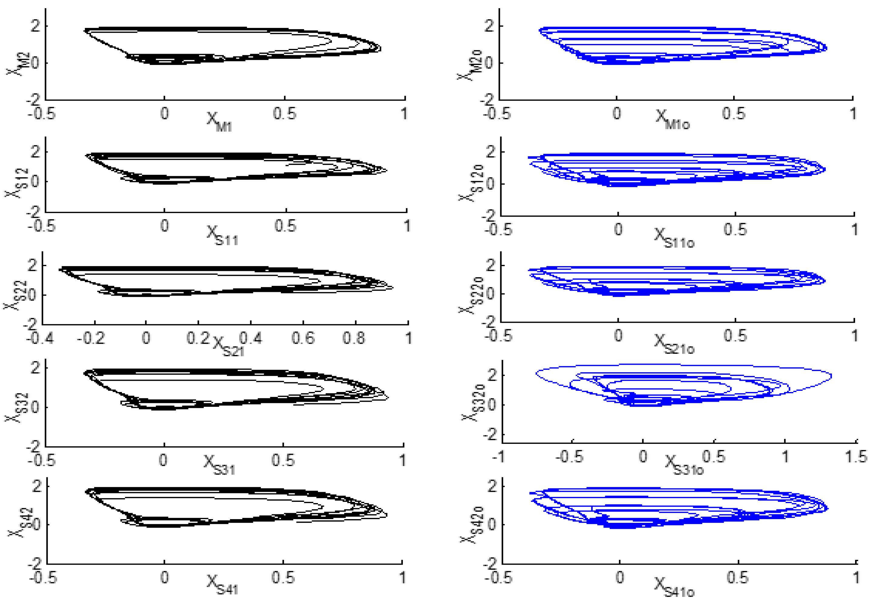
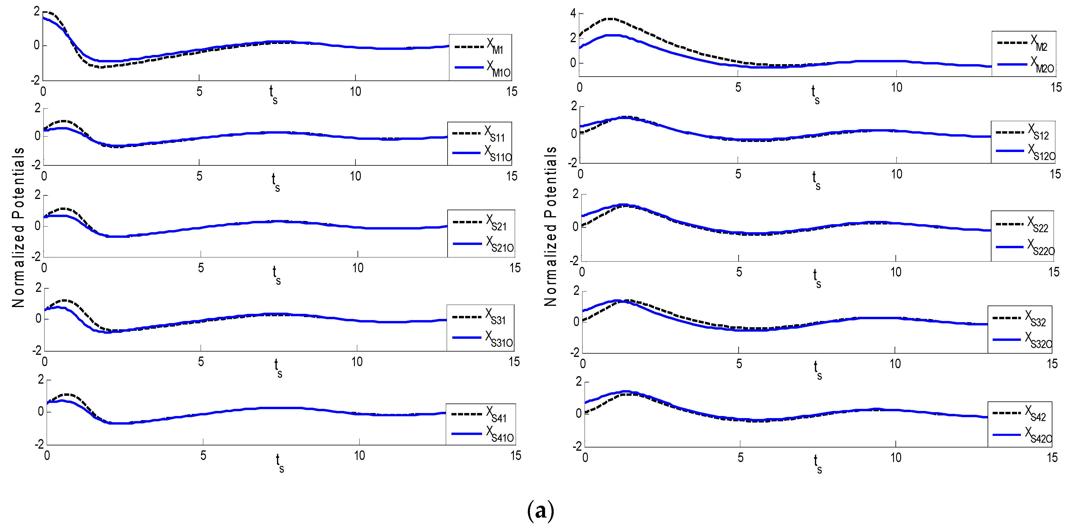
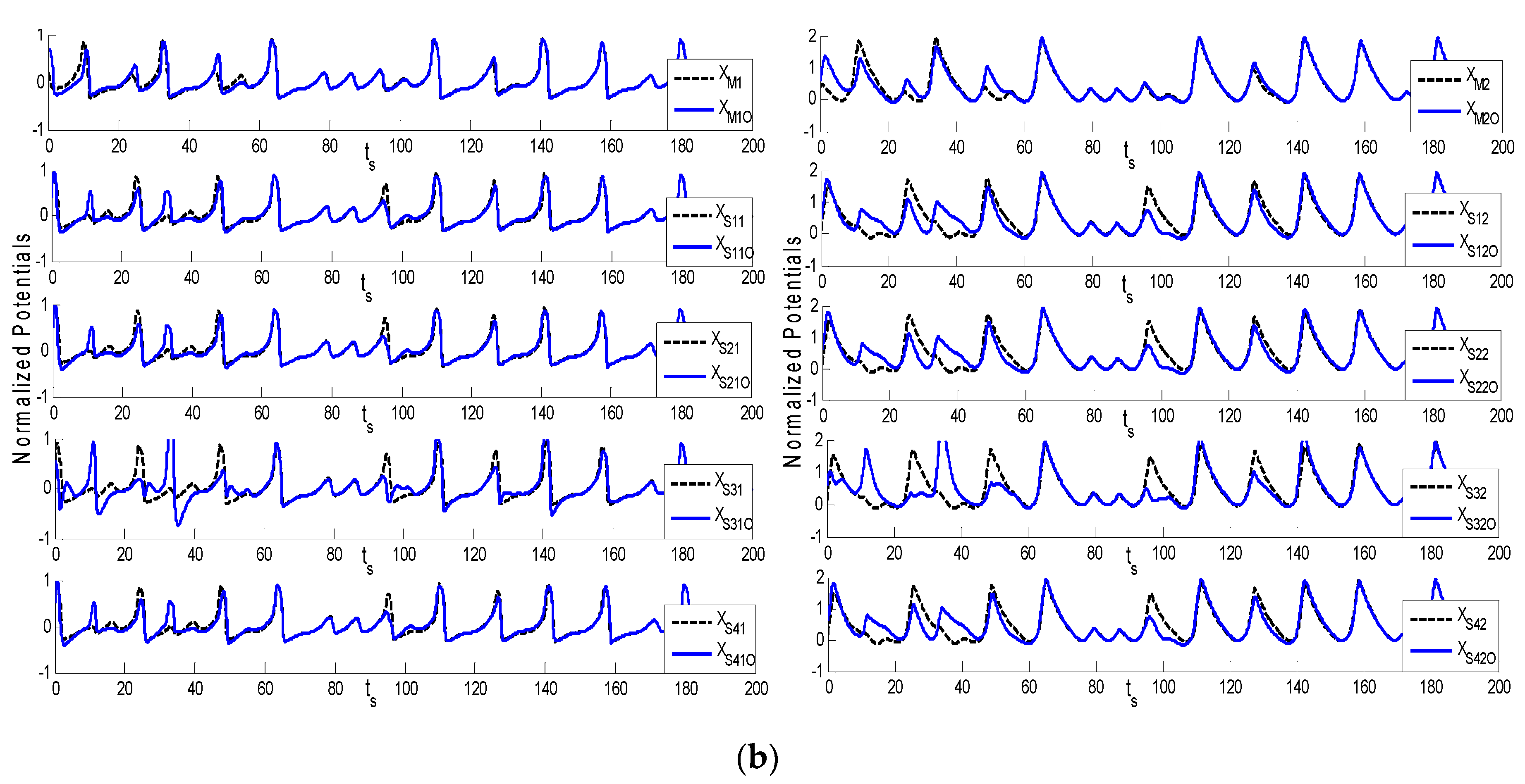
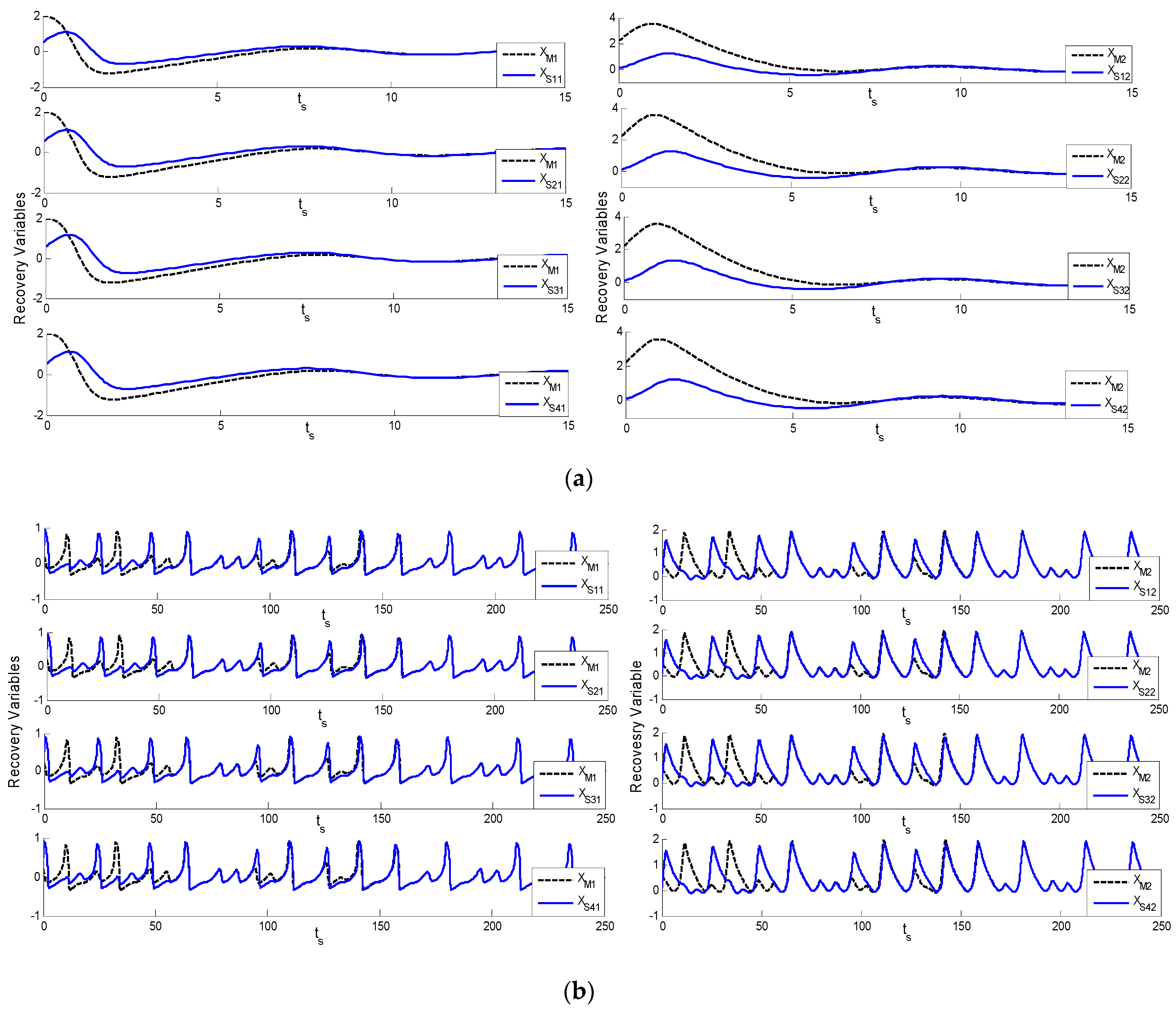
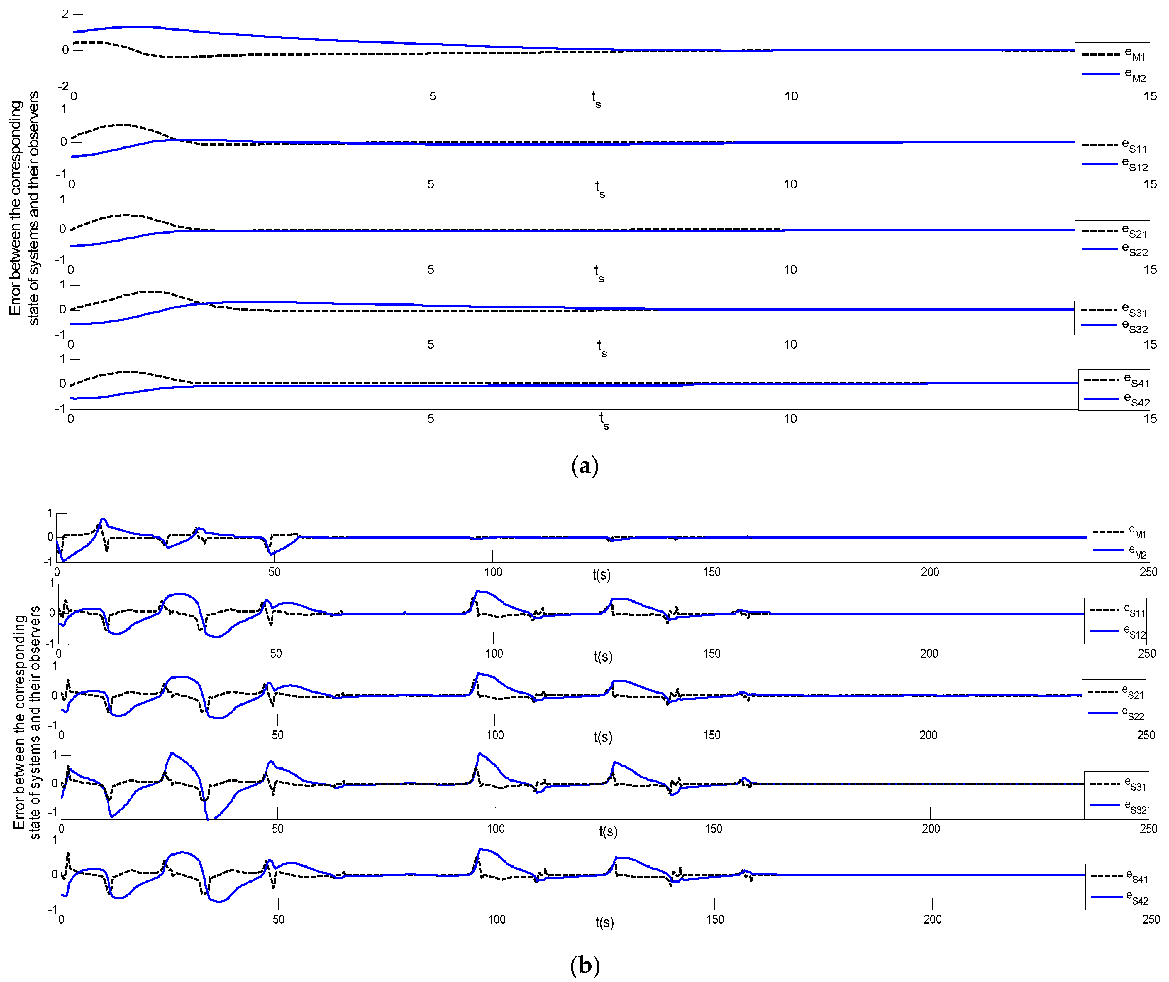
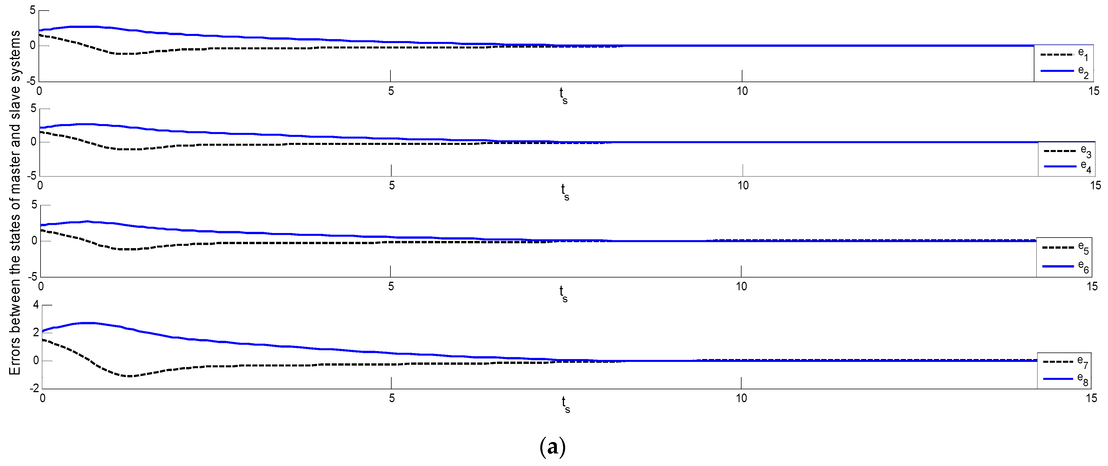
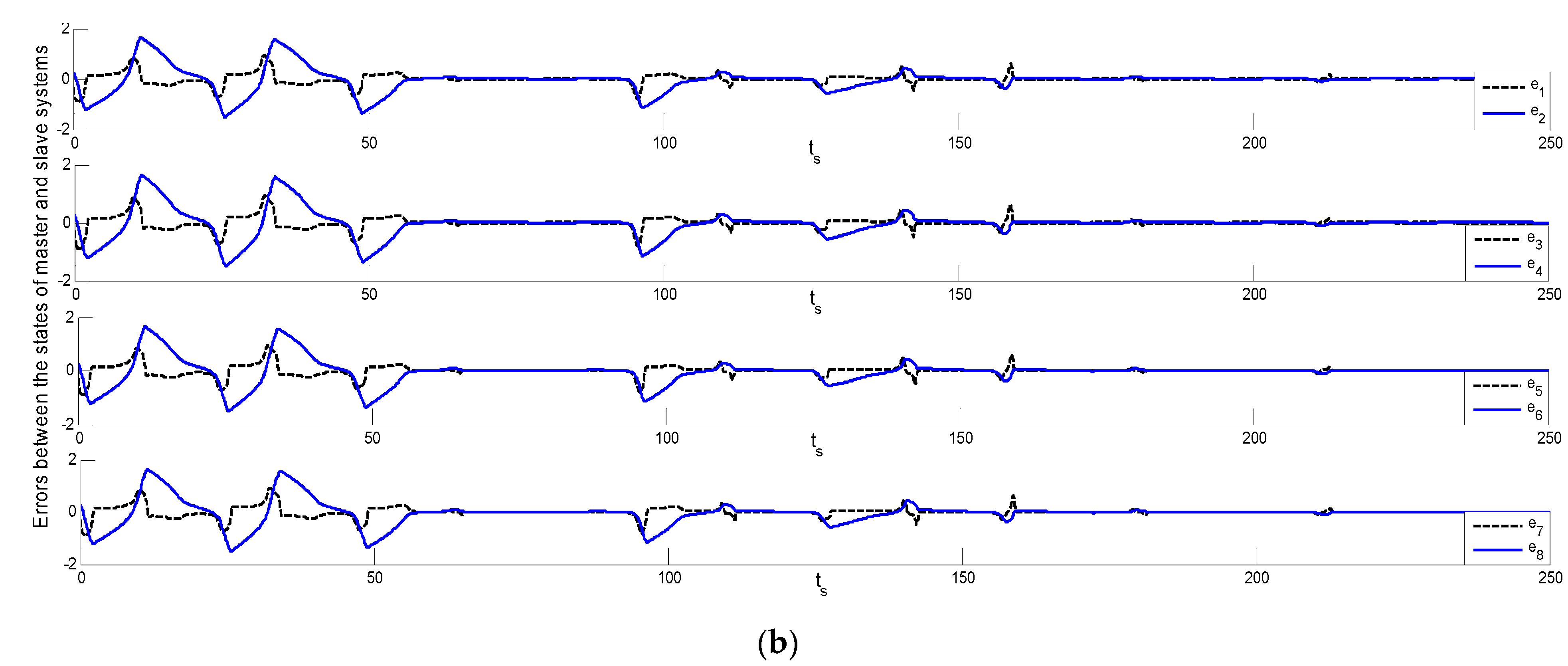
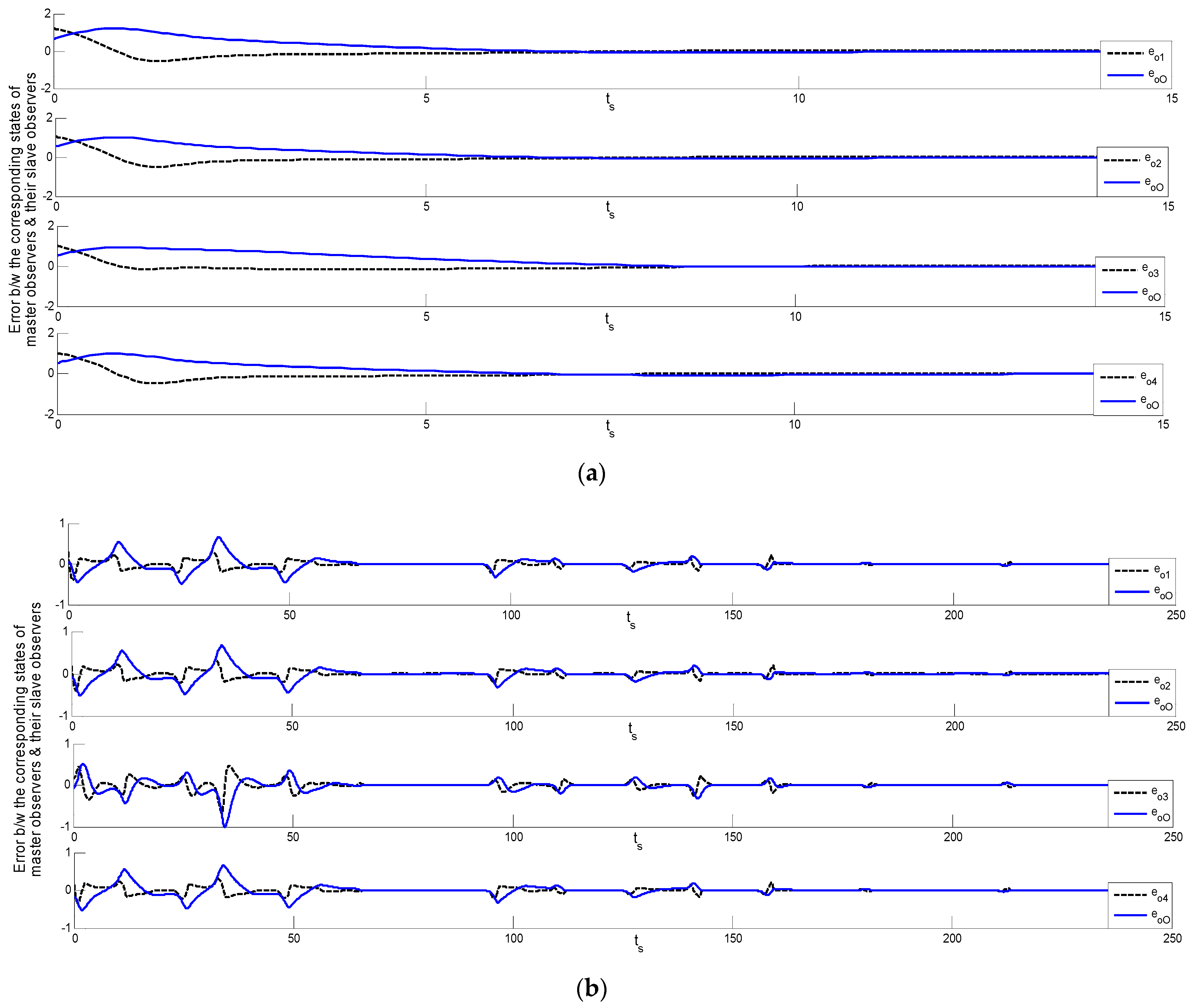
where I o is the current, I o = ( m / ω ) Cos ( ω t ) , ω = 2 π f , m = 0.099, and f = 0.128. Selected parameters, such as B , R 1 , R 2 and R i , are of the values B = 1.01 , R 1 = 10.09 , R 2 = 9.89 . The master and N-Slave systems’ initial conditions are assumed to be X s 1 ( 0 ) = 0.399 , X s 2 ( 0 ) = 0.099 , and X s 1 ( 0 ) = 0.399 ,   X s i + 1 ( 0 ) = 0.099 . The phase portrait and individual responses to the chaotic behavior of master and N-slave FHN systems are revealed in Figure 2. Figure 3 and Figure 4 representing master and N-slave for Theorems 1 and 2. The different initial conditions are used for the master and four slave systems. As the behavior of the complex chaotic systems has sensitive dependence on the intial conditions, so intial conditions are taken with care, i.e., are of low values. Errors are plotted between the corresponding states of the master system and its observer (XM-XMO) and the slave system states correspond to its observer (XSI-XSIO), presented in Figure 5a for Theorem 1 and Figure 5b for Theorem 2. Errors between the state of the master observer and the N-slave observer systems (XMO-XSIO) are set out in Figure 6a for Theorem 1 and Figure 6b for Theorem 2. Errors between the master observer state corresponding to the four slave observers’ states (XMO-XSOI) are described in Figure 7a for Theorem 1 and Figure 7b for Theorem 2. These errors are between the master and each slave system and their corresponding observers. The simulation results are provided from a non-adaptive control scheme under three conditions. First, the behavior of the neuron is generalized by the FHN system and the membrane potentials of the neurons are not similar in each species. These may be normalized by means of a different scaling factor, so this is applicable for all species of neurons. Second, the mathematical expressions of FHN are generally based on normal membrane potential. Third, the controller for normalized potential uses specific gain matrices to finally synchronize the master and N-slave systems.
The matrices associated with the FHN dynamics, according to the master and N-slave non-linear chaotic systems (1) and (2), are given below.
S i = [ 1.00 1.00 1.00 0.00 ] , X = [ 1.00 0.00 ] , Y = [ 1.00 0.00 ] F ( x ( t ) ) = [ 11.00 x 1 2 + 10.00 x 1 3 + ( m / ω ) C o s ( ω t ) 0.00 ]
We will synchronize the master and slave systems using a non-adaptive approach in Theorems 1 and 2. The gain matrices of the observers are LM, selected for the master, and LSI, selected for slave systems. The observer gain matrices and LM and LSI values can be selected with the help of an already-established technique, as mentioned in [42]. By using this technique, the suitable values for observer gain matrices Lm, Ls, and controller gain matrix F were selected as follows:
L m = [ 1.32 0.00 ] , L s i = [ 1.32 0.00 ] , F = [ 1.000.00 ] , ξ = F ( x ^ m ( t ) x ^ s i ( t ) ) ,
ξ is the controlling function of the controller and the results are shown in Figure 2, which sets out the results of the master and N-slave chaotic system behavior, the phase description of FHN master system, the four slave systems, and the portraits of their corresponding observers. Figure 3, showing Theorems 1 and 2, illustrates the normalized potential of the master and four slave systems and their respective observers, while Figure 4, showing Theorems 1 and 2, illustrates the master and four slave systems and their respective observer recovery variables. Errors exist between the corresponding states of the master system and its observer (XM-XMO) and the slave system and its corresponding observer (XM-XSIO), as described in Figure 5, showing Theorems 1 and 2. The gain matrices of the master and slave observers are Lm and Lsi, which may affect the em(t) and es(t). In Equation (17), ‘F’ may have a clear effect on the eoi(t). If we change the values of the gain matrices, these directly affect the synchronizing time. Figure 6, showing Theorems 1 and 2, outlines errors between the state of the master and four slave systems (XM-XSIO), and Figure 7, showing Theorems 1 and 2, demonstrates errors between the master observer states, corresponding to the four states of slave observers (XM-XSI).
Remark 4.
It is important to mention that, for simplification purposes, in simulations, the unknown parameter θ is considered as zero, which becomes the case discussed in Theorem 1.
5. Conclusions

The synchronization of the master and N-slave systems by means of CCS and CCAS observers was introduced. Using these observers, errors between the master and N-slave non-linear systems were reduced through application of the proposed methodology. The CCAS observer-based control has a slower response than the CCS observer-based control scheme. This is because adaptation requires more calculation on a real-time basis. The FHN neuronal system has been used for simulation to verify the authenticity of the proposed control scheme. The simulation results demonstrate and prove the claim and these systems are successfully synchronized by means of CCS and CCAS observer-based control. The proposed methodology can be further modified to manage the input and output delays, to synchronize multiple systems under communication constraints, and to deal with the input saturation problems.

Author Contributions

G.H. and M.M.H.: conceptualization, methodology, software, writing—original draft; G.H. and M.S.: writing—review and editing; M.T.H. and N.A.: data curation; M.M.H.: writing—review and editing. All authors have read and agreed to the published version of the manuscript.

Funding

This research received no external funding.

Institutional Review Board Statement

Not applicable.

Informed Consent Statement

Not applicable.

Data Availability Statement

Not applicable.

Conflicts of Interest

The authors declare no conflict of interest.

References

  1. Ott, E.; Grebogi, C.; Yorke, J.A. Controlling chaos. Phys. Rev. Lett. 1990, 64, 1196–1199. [Google Scholar] [CrossRef]
  2. Boccaletti, S.; Grebogi, C.; Lai, Y.C.; Mancini, H.; Maza, D. The control of chaos: Theory and applications. Phys. Rep. 2000, 329, 103–197. [Google Scholar] [CrossRef] [Green Version]
  3. Jiang, G.P.; Chen, G.; Tang, W.K.S. Stabilizing unstable equilibria of Chaotic systems from a state observer approach. IEEE Trans. Circuits Syst. II Express Briefs 2004, 51, 281–288. [Google Scholar] [CrossRef]
  4. Pecora, L.M.; Carroll, T.L. Synchronization in chaotic systems. Phys. Rev. Lett. 1990, 64, 821–824. [Google Scholar] [CrossRef] [PubMed]
  5. Cuomo, K.M.; Oppenheim, A.V. Circuit implementation of synchronized chaos with applications to communications. Phys. Rev. Lett. 1993, 71, 65–68. [Google Scholar] [CrossRef]
  6. Li, Y.; Chen, Y.Q.; Podlubny, I. Mittag-Leffler stability of fractional order nonlinear dynamic systems. Automatica 2009, 45, 1965–1969. [Google Scholar] [CrossRef]
  7. Tavazoei, M.S.; Haeri, M.; Bolouki, S.; Siami, M. Using fractional order integrator to control chaos in single-input Chaotic systems. Nonlinear Dyn. 2009, 55, 179–190. [Google Scholar] [CrossRef]
  8. Ahn, C.K.; Shi, P.; Basin, M.V. Two-dimensional dissipative control and filtering for Roesser model. IEEE Trans. Autom. Control. 2015, 60, 1745–1759. [Google Scholar] [CrossRef]
  9. Chen, M.; Shi, P.; Lim, C.C. Robust constrained control for MIMO nonlinear systems based on disturbance observer. IEEE Trans. Autom. Control. 2015, 60, 3281–3286. [Google Scholar] [CrossRef]
  10. Strogatz, S.H. Nonlinear Dynamics and Chaos: With Applications to Physics, Biology, Chemistry and Engineering; Westview Press: Boulder, CO, USA, 1994. [Google Scholar]
  11. Chadli, M.; Zelinka, I. Chaos synchronization of unknown inputs Takagi–Sugeno fuzzy: Application to secure communications. Comput. Math. Appl. 2014, 68, 2142–2147. [Google Scholar] [CrossRef]
  12. Gonzalez-Miranda, J.M. Synchronization and Control of Chaos: An Introduction for Scientists and Engineers; Imperial College Press: London, UK, 2004. [Google Scholar]
  13. Carroll, T.L.; Pecora, L.M. Synchronizing Chaotic circuits. IEEE Trans. Circuits Syst. 1991, 38, 453–456. [Google Scholar] [CrossRef] [Green Version]
  14. Liu, B.; Wang, L.; Jin, Y.H.; Huang, D.X.; Tang, F. Control and synchronization of Chaotic systems by differential evolution algorithm. Chaos Solitons Fract. 2007, 34, 412–419. [Google Scholar] [CrossRef]
  15. Mbe, E.S.K.; Fotsin, H.B.; Kengne, W. Parameters estimation based adaptive generalized projective synchronization (GPS) of Chaotic Chua’s circuit with application to chaos communication by parametric modulation. Chaos Solitons Fract. 2014, 37, 27–37. [Google Scholar]
  16. Yang, J.; Zhu, F. Synchronization for Chaotic systems and chaos-based secure communications via both reduced-order and step-by-step sliding mode observers. Sci. Numer. Simul. 2012, 18, 926–937. [Google Scholar] [CrossRef]
  17. Yang, C.C. Adaptive control and synchronization of identical new Chaotic flows with unknown parameters via single input. Appl. Math. Comput. 2010, 216, 1316–1324. [Google Scholar] [CrossRef]
  18. Yang, C.C. Adaptive synchronization of Lü hyper Chaotic system with uncertain parameters based on single-input controller. Nonlinear Dyn. 2011, 63, 447–454. [Google Scholar] [CrossRef]
  19. Njah, A.N. Tracking control and synchronization of the new hyperChaotic Liu system via back stepping techniques. Nonlinear Dyn. 2010, 61, 1–9. [Google Scholar] [CrossRef]
  20. Jeong, S.C.; Ji, D.H.; Park, J.H.; Won, S.C. Adaptive synchronization for uncertain Chaotic neural networks with mixed time delays using fuzzy disturbance observer. Appl. Math. Comput. 2013, 219, 5984–5995. [Google Scholar] [CrossRef]
  21. Rehan, M.; Hong, K.S. Robust synchronization of delayed Chaotic Fitz Hugh–Nagumo neurons under external electrical stimulation. Comput. Math. Methods Med. 2012. [Google Scholar] [CrossRef]
  22. Zaheer, M.H.; Rehan, M.; Mustafa, G.; Ashraf, M. Delayrange-dependent chaos synchronization approach under varying time-lags and delayed nonlinear coupling. ISA Trans. 2014, 53, 1716–1730. [Google Scholar] [CrossRef]
  23. Ramirez, J.P.; Fey, R.H.B.; Nijmeijer, H. Synchronization of weakly nonlinear oscillators with Huygens’ coupling. Chaos 2013, 23, 033118. [Google Scholar] [CrossRef] [PubMed] [Green Version]
  24. Beyhan, S. Runge–Kutta model-based nonlinear observer for synchronization and control of Chaotic systems. ISA Trans. 2013, 52, 501–509. [Google Scholar] [CrossRef]
  25. Abdullah, A. Synchronization and secure communication of uncertain Chaotic systems based on full-order and reduced order output-affine observers. Appl. Math. Comput. 2013, 219, 10000–10011. [Google Scholar] [CrossRef]
  26. Yassen, M.T. Controlling chaos and synchronization for new Chaotic system using linear feedback control. Chaos Soliton Fract. 2005, 26, 913–920. [Google Scholar] [CrossRef]
  27. Mirollo, R.E.; Strogatz, S.H. Synchronization of puls ecoupled biological oscillators. SIAM J. Appl. Math. 1990, 50, 1645–1662. [Google Scholar] [CrossRef]
  28. Filal, R.L.; Benrejeb, M.; Borne, P. On observer-based secure communication design using discrete-time hyper Chaotic systems. Commun. Nonlinear Sci. Numer. Simul. 2014, 19, 1424–1432. [Google Scholar] [CrossRef]
  29. Angeles, N. Mutual synchronization of robots via estimated state feedback: A cooperative approach. IEEE Trans. Contr. Syst. Technol. 2004, 12, 542–554. [Google Scholar] [CrossRef]
  30. Steinmetz, P.N.; Roy, A.; Fitzgerald, P.J. Attention modulates synchronized neuronal firing in primate soma tosensorycortex. Nature 2000, 404, 457–490. [Google Scholar] [CrossRef] [PubMed]
  31. Meffo, L.P.; Woafo, P.; Domnganga, S. Cluster states in a ring of four coupled semiconductor lasers. Commun. Nonlinear Sci. Numer. Simul. 2007, 12, 942–952. [Google Scholar] [CrossRef]
  32. Li, Y.N.; Chen, L.; Cai, Z.S.; Zhao, X.Z. Experimental study of chaos synchronization in the Belousov–Zhabotinsky chemical system. Chaos Solitons Fract. 2004, 22, 767–771. [Google Scholar] [CrossRef]
  33. Kuhnert, L.; Agladze, K.I.; Krinsky, V.I. Image processing using light sensitive chemical waves. Nature 1989, 337, 244–247. [Google Scholar] [CrossRef]
  34. Ömer, M.; Ercan, S. Observer based synchronization of Chaotic systems. Phys. Rev. 1996, E54, 4803–4811. [Google Scholar]
  35. Heagy, J.F.; Carroll, T.; Pecora, L. Synchronous chaos in coupled oscillator systems. Phys. Rev. 1994, E50, 1874–1885. [Google Scholar] [CrossRef] [PubMed]
  36. Bagheri, P.; Shahrokhi, M.; Salarieh, H. Adaptive observer-based synchronization of two non-identical Chaotic systems with unknown parameters. J. Vib. Control 2015. [Google Scholar] [CrossRef]
  37. Grassi, G. Observer-based hyper chaos synchronization in cascaded discrete-time systems. Chaos Solitons Fract. 2009, 40, 1029–1039. [Google Scholar] [CrossRef]
  38. Rigatos, G.; Siano, P.; Abbaszadeh, M. A Nonlinear Optimal Control Method for Synchronization of Distributed Hydropower Units. In Proceedings of the 2019 IEEE PES Innovative Smart Grid Technologies Europe (ISGT-Europe), Bucharest, Romania, 29 September–2 October 2019; pp. 1–5. [Google Scholar]
  39. Siddique, M.; Rehan, M. A concept of coupled chaotic synchronous observers for nonlinear and adaptive observers-based chaos synchronization. Nonlinear Dyn. 2016, 84, 2251–2272. [Google Scholar] [CrossRef]
  40. Shang, W.; Zhang, B.; Zhang, B.; Zhang, F.; Cong, S. Synchronization control in the cable space for cable-driven parallel robots. IEEE Trans. Ind. Electron. 2018, 66, 4544–4554. [Google Scholar] [CrossRef]
  41. Khorashadizadeh, S.; Majidi, M.H. Chaos synchronization using the Fourier series expansion with application to secure communications. AEU Int. J. Electron. Commun. 2017, 82, 37–44. [Google Scholar] [CrossRef]
  42. Che, Y.Q.; Wang, J.; Chan, W.L.; Tsang, K.M. Chaos synchronization of coupled neurons under electrical stimulation via robust adaptive fuzzy control. Nonlinear Dyn. 2010, 61, 847–857. [Google Scholar] [CrossRef]
  43. Yang, C.C.; Lin, C.L. Robust adaptive sliding mode control for synchronization of space-clamped FitzHugh–Nagumo neurons. Nonlinear Dyn. 2012, 69, 2089–2096. [Google Scholar] [CrossRef]
Figure 1. (a) Architecture of the master and N-slave systems with their corresponding observers; (b) block diagram of the master and slave systems with respect to their observers.
Energies 14 03190 g001
Figure 2. Phase portraits of master and slave systems of Theorem 2.
Energies 14 03190 g002
Figure 3. (a) Normalized potential of the master and four slave systems; (b) the respective observers of Theorems 1 and 2.
Energies 14 03190 g003aEnergies 14 03190 g003b
Figure 4. (a) Master and four slave systems and their respective observers; (b) observer recovery variables of Theorems 1 and 2.
Energies 14 03190 g004
Figure 5. Errors between the corresponding states of master and observer: (a) (XM-XMO) and slave; (b) corresponding observer (XSI-XSIO) of Theorems 1 and 2.
Energies 14 03190 g005
Figure 6. Errors between the state: (a) master; (b) four slave systems (XMO-XSIO) of Theorems 1 and 2.
Energies 14 03190 g006aEnergies 14 03190 g006b
Figure 7. (a) Errors between the master observers’ states; (b) corresponding to the four states of slave observers (XM-XSI) of Theorems 1 and 2.
Energies 14 03190 g007
Publisher’s Note: MDPI stays neutral with regard to jurisdictional claims in published maps and institutional affiliations.