1. Introduction
TPCT is the most efficient technology for transferring a larger amount of heat in a small cross-section for a considerable distance, without any external power inputs. Typically, the TPCT is fabricated using a wide range of materials such as copper, stainless steel, nickel, aluminum and molybdenum along with various working fluid including water, methanol, ethanol, lithium, bismuth, sodium, cesium and certain nanofluids [
1]. In most of the TPCT, the evaporator is located at the bottom and the condenser and adiabatic sections are placed above the evaporator to make use of gravitational force. The working fluid inside the TPCT absorbs the heat and turns into a vapor when the added heat in the evaporator is more than its latent heat of enthalpy. Due to a lower density of vapor compared to its liquid state, the vapor rises through the adiabatic section to the condenser section where the latent heat is rejected. The TPCT is used as pioneering thermal management equipment in electronics, aerospace and solar units in cooling applications owing to its lesser space requisition and design flexibility [
2]. Many investigations have been carried out to enhance the heat transfer by varying different parameters such as filling ratio of fluid, working fluid used, geometry, heat input power, orientation angles and surface roughness [
3].
On the other hand, the boiling of the working fluid and the surface roughness of the material are crucial for predicting the dynamics of working fluid [
4]. When dealing with high thermal performance fluids such as CuO-water, Al
2O
3-water and Carbon Nano Tube (CNT) nanofluids in TPCT, higher performance was obtained for CNT nanofluids than all other base fluids [
5]. This is because the CNT nanofluid tends to improve the nucleate boiling [
6]. Apart from various working fluids, focusing on heat transfer enhancement by achieving optimum mass concentrations is pivotal. For instance, a study highlights that the optimal mass concentrations of copper nanoparticles were identified to be about 1 wt% to obtain a maximum heat transfer rate [
7]. The stability of Al
2O
3 nanofluid on TPCT was analyzed with two different surfactants such as Sodium Dodecyl Benzene Sulfonate (SDBS) solution and Cetyl Trimethyl Ammonium Bromide (CTAB), and then it was compared without surfactant nanofluids. The stability of Al
2O
3 particles in water was improved by about 24% with SDBS when compared to deionized water and 8% relative to CTAB [
8]. The TPCT was used to remove the heat from Multi-Chip Modules (MCM), and it was found that the volume of the condenser and the liquid quantity emerges to be higher influencing factors in the thermal performance of TPCT [
9]. Gravity-based TPCT was assessed with various working fluids such as water, R134a, SES36, ethanol and HFE7100. The best results were identified with R134a and ethanol. Sometimes, R134a worked better in lower evaporation temperatures [
10]. Using n-pentane-acetone and n-pentane-ethanol binary mixture on thermosiphon resulted that n-pentane-acetone has better thermal efficiency than other mixture. Furthermore, it was identified that 55° of inclination produced a better performance for binary mixtures, whereas 65° for pure liquid [
11].
A gravity-driven heat pipe made of alkali metal possessing higher heat transfer capacity was tested at various inclination angles. A better heat transfer rate was identified between the 0° and 50° inclination. However, the heat transfer rate starts to decrease when the inclination is above 60° [
12]. The TPCT with tilted evaporator (30° and 60°) was tested in the varied filling ratios of 15% to 60%. In this case, the heat transfer coefficient was improved up to 15.2% in the 60° inclination with 45% of the filling ratio [
13]. The copper nanoparticle with a concentration of 10, 30 and 50 ppm was used with water on TPCT and performance improvement was around 4% with 50 ppm concentration compared with normal water [
14]. The experimentations were carried out with TPCT using Ni/Glycerol-water nanofluid in three concentrations, namely 0.426, 0.625 and 1.25 g/lit. The lower thermal resistance was exhibited by the working fluid having a concentration of 0.625 g/lit and it is highly sensitive to the evaporator and condenser temperatures [
15]. The TPCT was tested using Al
2O
3 nanofluid with different inclinations, various heat inputs and different concentrations of Al
2O
3. The inclination angles were 30, 45, 60 and 90 degrees, the heat input was varied as 4, 8 and 13 W and the Al
2O
3 concentration varied from 0.05% to 0.25%. The thermal resistance was reduced by up to 36.4% corresponding to 0.25 vol% of Al
2O
3 nanoparticles, at 60° inclination for 4 W of heat input when compared to other experimental configurations [
16]. The graphene nanoplatelets can reduce the thermal resistance value by increasing the concentration and also by increasing the heat load to the evaporator [
17]. When water is used as a fluid medium in TPCT, it can operate effectively for fill ratios ranging from 30 to 90% with respect to the total volume of the TPCT up to 350 W of heat input. Heat input highly influences the optimum orientation angle [
18].
Beyond the influence of various working fluids on TPCT performance, only a few works investigated the influence of geometry on heat transfer enhancement. Tong and Zang investigated the influence of riser and downcomer diameter on the heat transfer rate of the CO
2 thermosiphon loop that is utilized in data centers. When the diameter is increased from 6 to 12 mm, the maximum heat transfer capacity was enhanced from 1500 to 5400 W. Besides, it is also observed that the effect of diameter variation on the resulted temperature difference was not that obvious [
19]. Furthermore, increasing the riser diameter would yield a higher circulating mass flow rate [
20]. In a study, a dual taper was provided at the evaporator section to enable the highly efficient two-phase flow of HFE7000 in CPU cooling application and it produced better heat transfer performance than single taper geometry [
21]. In an experimental study conducted by Zhu and Hrnjak, the vapor from the evaporator through the adiabatic section was separated and allowed to the condenser. This separation led to the improvement of the performance and exhibited a quick startup without adverse oscillations in flow which also helped to reduce the condenser size [
22]. The increase of internal surface roughness decreased the evaporator temperature and thermal resistance. This yielded in an improved heat transfer coefficient up to 115% at 3 kPa condition [
23]. Research also emphasizes the aid of the convergent section in augmenting the heat transfer rate. Ahmed and Kambiz showed that the heat transfer rate and pressure drop raises as the convergence angle is increased. The accelerating flow increases the pressure drop resulting in an attractive rise of heat transfer [
24]. The heat transfer and pressure drop in Convergent-Divergent ducts were numerically analyzed, and they indicate that an increase of convergence angle leads to the enhancement of both pressure drop and Nusselt number whereas the increment of divergence angle may reduce the pressure drop and no significant variation of Nusselt number was perceived [
25]. Furthermore, the convergent angle of 3° in the vertical channel enhanced the Nusselt number in downstream [
26]. The different convergent angles (horizontal, 2.5°, 5° and 7.5°) were tested in heat transfer applications and the results show that the rate of heat transfer was increased with the increment of taper angle up to 5° [
27].
From this review of previous investigations, it has been found that most of the research studies were concentrated on various working fluids in TPCT operations. Very limited works were reported on the influence of geometrical changes on heat transfer performance, especially by branching the evaporator section and increasing the internal surface roughness. However, no work was found to analyze the influence of geometrical changes in the adiabatic portion (introducing convergent and divergent) on heat transfer coefficient. This research work is proposed to fill this research gap. By introducing the convergent and divergent sections within the adiabatic segment, the dynamics of fluid can be favorably varied to enhance the heat transfer significantly. The convergent section accumulates the fluid which results in an increase in the temperature with mild pressure increase. During the flow in the convergence pathway, the boundary layer is interrupted and is redeveloped. This enhances the heat transfer and a slight drop in temperature is desired but it may be countered by increased flow resistance or friction factor in the converging section. The divergent section increases the flow area which induces turbulence in the flow by increasing the Reynolds number and thus, achieving a higher heat transfer coefficient near the condenser by improving the average Nusselt number [
28]. Therefore, the convergent-divergent section cumulatively reduces pressure at the condenser side and slightly increases at the evaporator side. With the influence of turbulence, pressure variations and disrupted boundary layers, the overall heat transfer coefficient is enhanced in NUAS TPCT relative to UAS TPCT.
The objective of this work is to analyze the heat transfer performance in TPCT with a non-uniform adiabatic section, using DI water as working fluid. The performance variation with various inclination angles such as 0, 45 and 90 degrees are also assessed, as well as the analysis is extended for various heat input ranging from 50 W to 250 W. The results from each test have been compared and contrasted with the TPCT having a uniform adiabatic section.
This study consists of various sections. The background of this research, previous investigations, research gap and objective of research are discussed in this section. The materials used for the fabrication of TPCT and other supplementary equipment adopted in the layout are discussed in
Section 2, with an insight on various formulae to find the uncertainties and few non-dimensional numbers. The results and discussion are split into four sub-sections for analyzing the effect of geometrical changes along with different setting angles on (i) thermal resistance, (ii) wall temperature, (iii) heat transfer co-efficient and (iv) non-dimensional numbers. Finally, a conclusion is drawn in
Section 4.
2. Materials and Methods
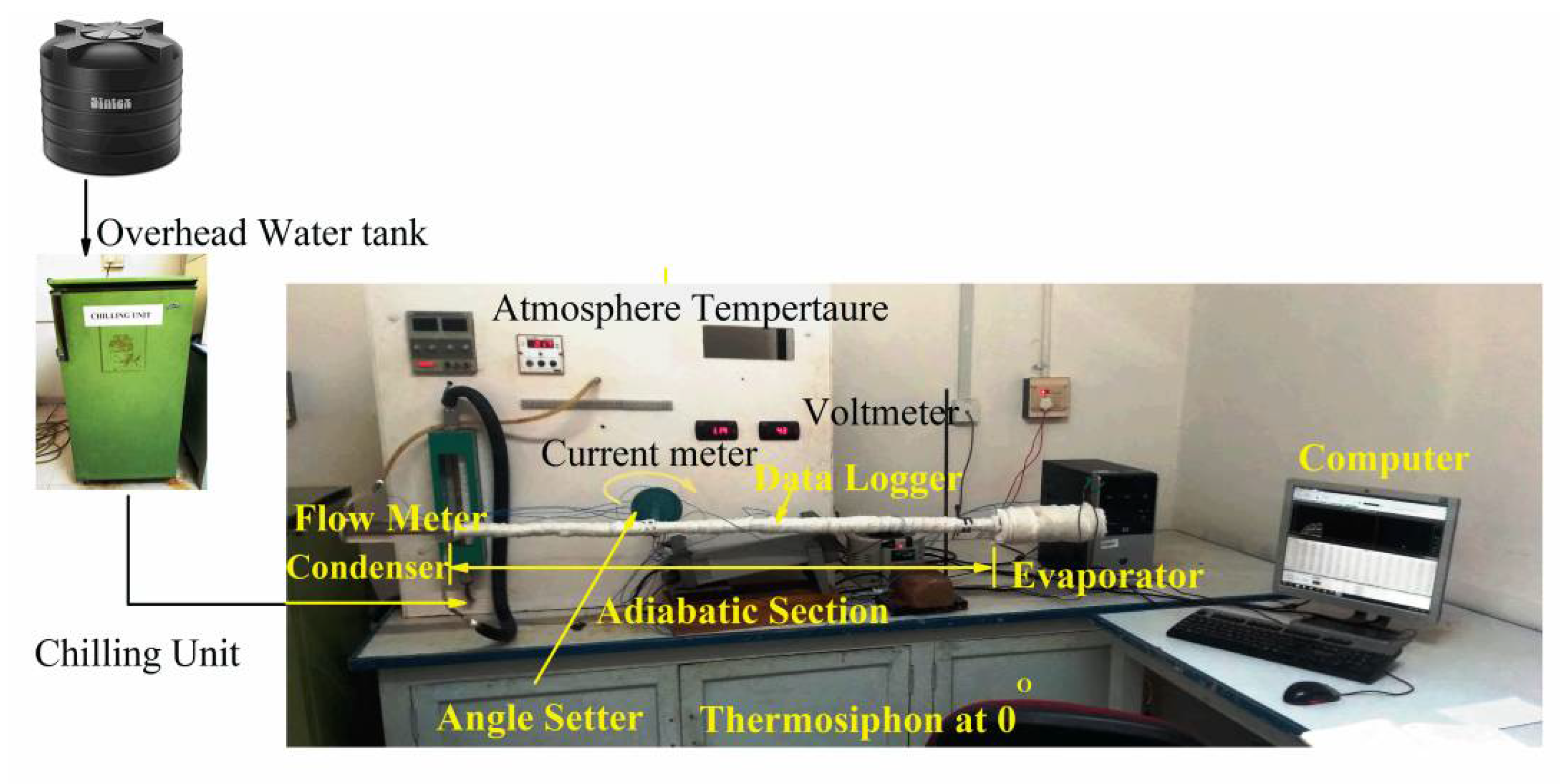
The experimental set-up for testing and analyzing the proposed TPCT configuration is shown in
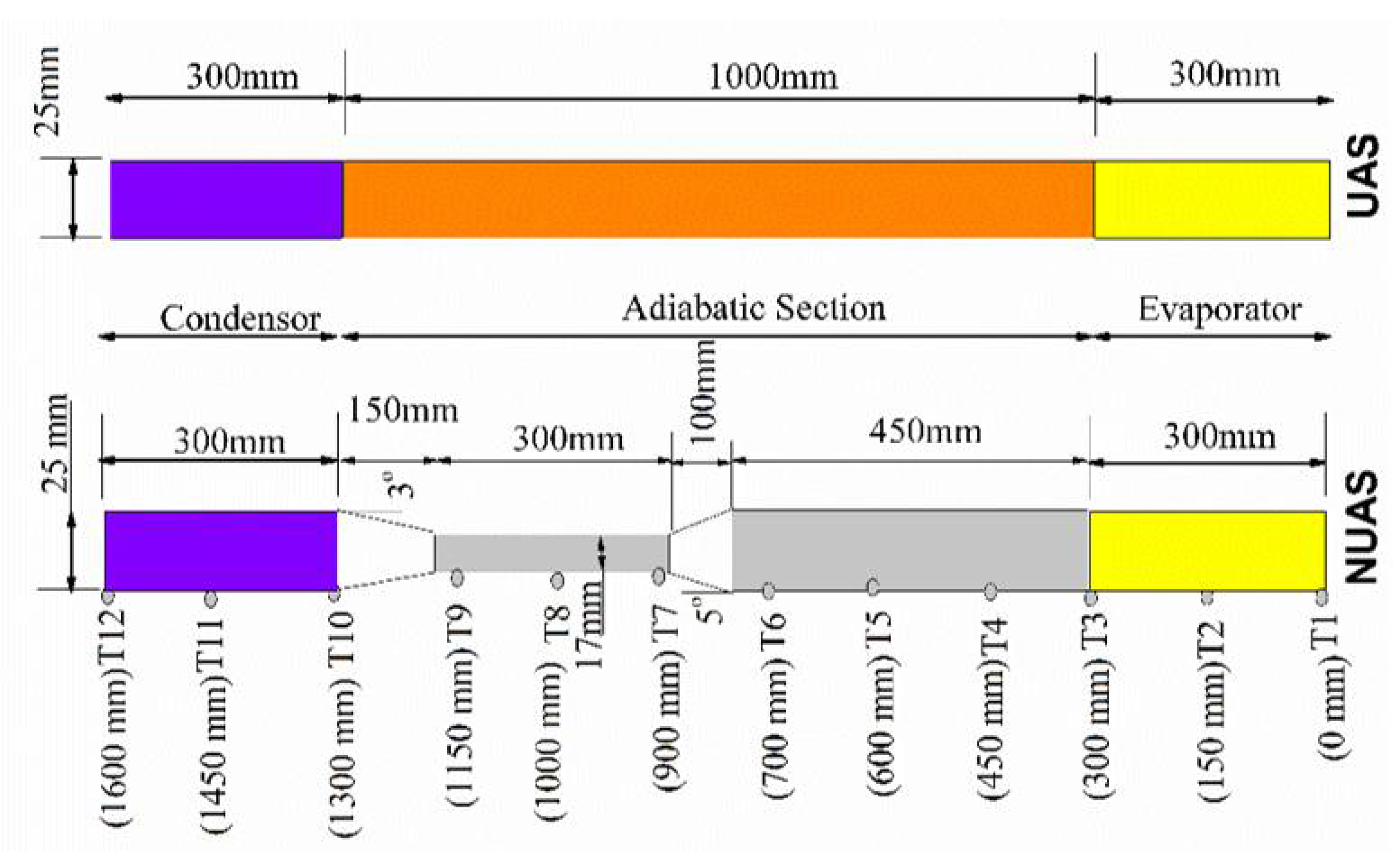
Figure 1. The equipment used for experimental investigation includes a resistance heater, voltmeter, Ammeter, Refrigeration unit, transformer, and data acquisition unit (Agilent 34972A) with the computer. The data are acquired for every 30 s or at 0.033 Hz frequency and the accuracy of the acquisition system was ±0.2%. Two copper TPCTs were fabricated in which one possesses Uniform Adiabatic Section (UAS), while the other has the Non-Uniformed Adiabatic Section (NUAS). In both TPCTs, the outer diameter of the TPCT was 25 mm, the evaporator and condenser length was 300 mm with 0.8 mm of wall thickness. The length of the adiabatic section was about 1000 mm. However, in NUAS TPCT the adiabatic section has been modified with convergent and divergent sections instead of the uniformed cross-section. Introducing a convergent and divergent section into the adiabatic portion of the thermosiphon (nearer to the condenser part) enhances the heat transfer by the pressure drop in the condenser side [
24]. The taper angle of 5° is provided to the converging section based on the results of existing research on the heat transfer performance analysis on convergent ducts [
27]. To recover the pressure partially and to sustain the acceleration of the flow-induced in the convergent section, a lesser taper angle of 3° is preferred. Furthermore, to avoid higher pressure rise and pressure drop, the angle of convergent and divergent are kept as 5° and 3°. The dimensions of diffuser and nozzle sections are calculated based on the degree of taper. Twelve T type thermocouples are fitted to measure the temperature distribution on the wall of the entire set-up. The thermocouples were calibrated before fixing by dry block method using CALsys 650 Autocal (temperature range from 50 to 650 °C). The error of temperature measurement was found as ±0.2%. The dimensions and position of thermocouples of the UAS TPCT and NUAS TPCT are represented in
Figure 2. To be more specific, three thermocouples are fitted at both the evaporator and the condenser section. The average values from these thermocouples are considered as Te and Tc. The remaining six thermocouples are fixed in the adiabatic segment of TPCT. The thermocouples are attached to the data logger and computer for monitoring and storing the data. The cooling jacket using acrylic material is fitted around the condenser portion and the water from the chilling unit is passed to the condenser. The chilling unit is used to maintain the temperature of inlet water at 18 °C with a flow rate of 290 mL/min. The experimental parameters for this analysis are given in
Table 1. The fiber glass mat with 4 cm thickness is used for insulation around the adiabatic section for preventing heat loss.
2.1. Error and Uncertainty Assessment
From the previous investigations, the optimal filling ratio was fixed as 30 vol%, and the water flow rate to the condenser was also fixed as 290 mL/min. The rate of water flow was obtained from trial runs at which minimum temperature difference was found. All the thermocouples were calibrated before fixing by dry block method using CALsys 650 Autocal (temperature range from 50 to 650 °C). The estimated accuracy in measuring the temperature and flow rate is ±0.2% and ±3%, respectively. Furthermore, the uncertainties of data logger and thermocouples are ±0.6% and ±0.2°. The uncertainties of heat flux, heat transfer coefficient and thermal resistance have been calculated using the following relations [
29]:
The calculated uncertainties for heat flux, heat transfer coefficient and thermal resistance are less than 6.2% at lower heat input. Furthermore, it was reduced to 3.4% at higher heat input. Moreover, few constraints were noted during the operation of TPCT such as dry out, flooding, counterflow and boiling limitations. Among these, dry out and counter flow limitations are important constraints. A sudden rise in the evaporator temperature will indicate the dry out conditions. Thus, the temperature at the evaporator was monitored continuously to check the possibilities of dry out and counterflow patterns.
2.2. Estimation of Heat Transfer Parameters
The heat transfer coefficient for both evaporator and condenser, and thermal resistance were calculated by the following Equations (4)–(8):
where
he and
hc represent the heat transfer coefficient of evaporator and condenser,
qe and
qc indicate heat flux in evaporator and condenser, and
Te,
Tc and
Ta denote the average temperature at the evaporator, condenser and adiabatic section, respectively. The
qe and
qc were calculated using Equations (6) and (7).
where
le and
lc is the length of evaporator and condenser, respectively, and
is the transferred heat power in TPCT. Furthermore, the total thermal resistance was obtained using Equation (8).
2.3. Estimation of Non-Dimensional Parameters
To analyze the effect of sudden geometrical changes in the adiabatic section of TPCT on heat transferability, the following non-dimensional parameters are used. The non-dimensional parameters are Bond (BO), Weber (WE), Kutateladze (KU) and condensation (CO) [
30]. Here, the BO is used to analyze the need for the surface tension of working fluid as compared with body forces. It is the ratio of buoyancy force to the surface tension. The higher the value, the higher is the boiling capability by diminishing the influence of surface tension. Furthermore, this number is calculated by the Equation (9)
where
D is the inner diameter,
g is the acceleration due to gravity,
and
represents the density of the fluid in liquid and vapor corresponding to the saturation state,
is the interfacial surface tension of the fluid.
The WE number is used to analyze the interaction between liquid and vapor phases, and it is calculated using Equation (10)
where
Q is the heat transfer and
hfg indicates the latent heat of enthalpy of the working fluid. When a higher momentum flux of vapor exists in thermosiphon, the liquid droplets may be carried away along with the vapor flow due to large shear stress interaction between liquid and vapor surface. The extent of this phenomenon is determined by using the Weber number. The KU denotes the pool boiling occurrence in the evaporator of TPCT, and it is determined by Equation (11)
The
CO is used to find the amount of liquid returned to the evaporator from the condenser and it is measured by the following Equation (12):
where
h is heat transfer co-efficient and
k is thermal conductivity,
is the viscosity of the fluid. Therefore, fluid properties such as surface tension, latent heat, specific heat capacity and viscosity are pivotal to enhance the performance of thermosiphon. Higher surface tension allows for increasing maximum allowable pressure drop and diameter to enhance the performance. However, higher heat input is required when a larger diameter is preferred to sustain the pulsating flow. A less latent heat aids in vaporizing the liquid quickly and induces higher vapor pressure. This enhances the heat transfer performance of thermosiphon by increasing the liquid slug oscillating velocities. A fluid with a high specific heat capacity is preferable since the majority of the heat transfer is occurred by means of sensible heat. Low dynamic viscosity is desired because it will decrease the shear stress along the wall. This will mitigate the pressure drop inside the tube.
3. Result and Discussion
In this present analysis, the effect of geometrical changes in the adiabatic section for different setting angles (0°, 45° and 90°) corresponding to various heat input (50 to 250 W) on TPCT thermal performance was studied. The temperature of the TPCT wall at different places, the flowing rate of cooling water, current inputs were recorded for each set of experiments. Using inputs and other parameters, the heat transfer resistance, thermal conductivity, and non-dimensional number were estimated and discussed in the following section.
3.1. The Effect of Geometrical Changes in the Adiabatic Section and Setting Angle on Thermal Resistance
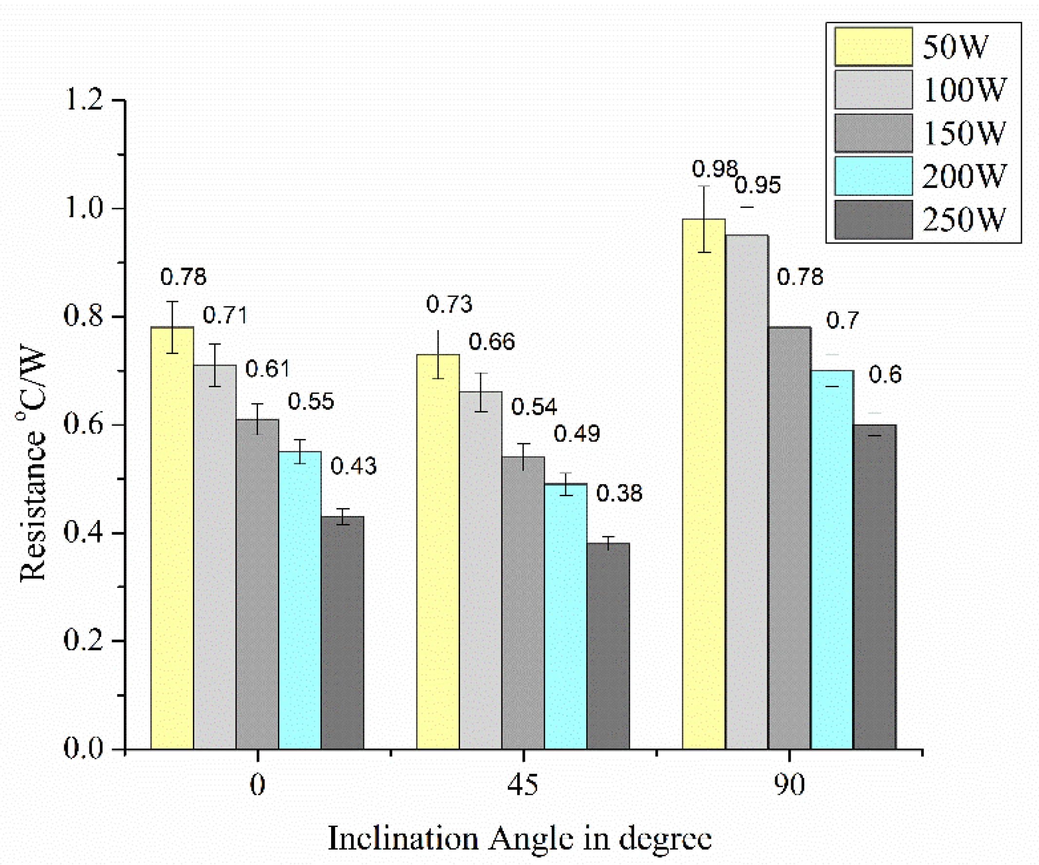
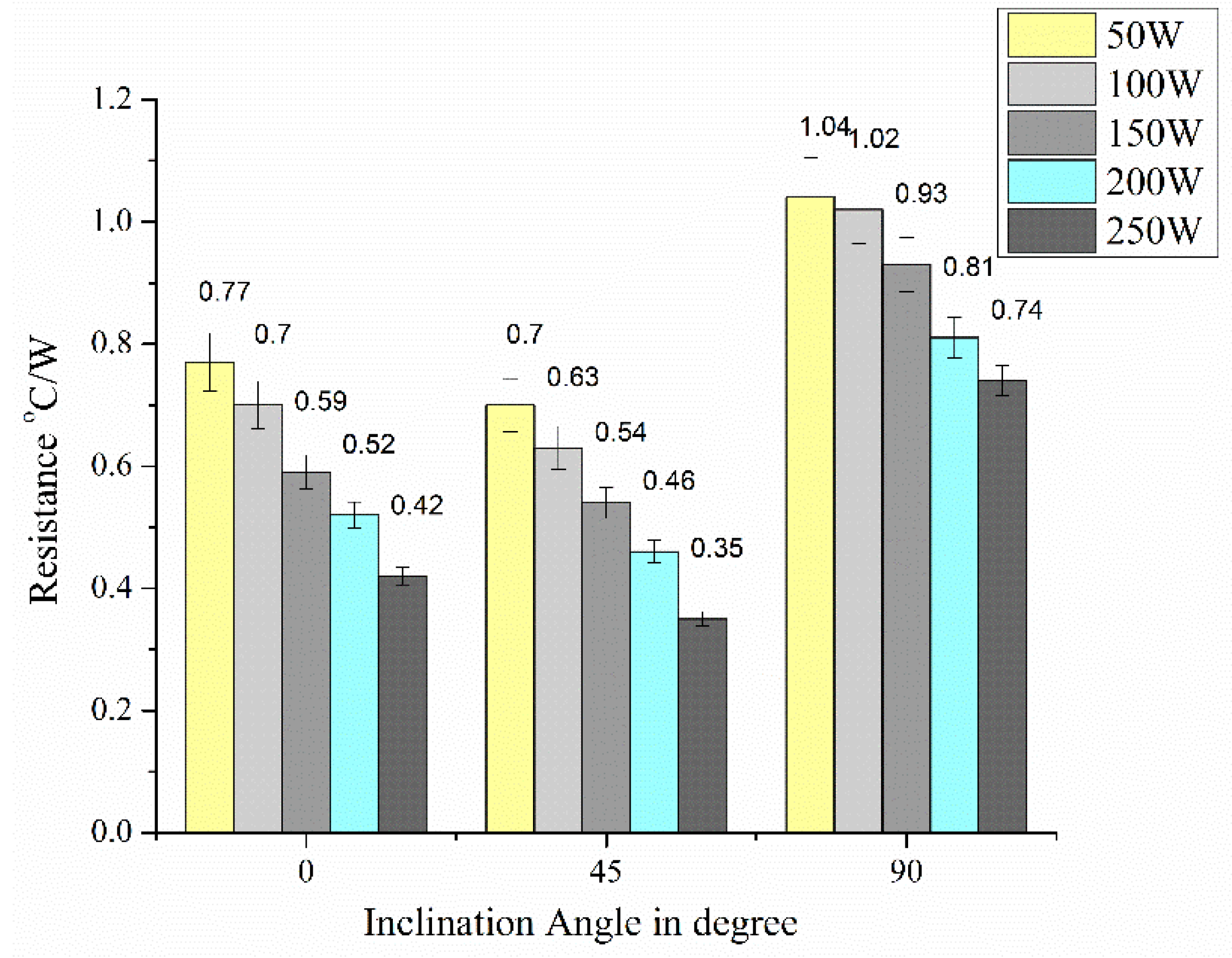
Figure 3 and
Figure 4 show the changes in thermal resistance among various setting angles in both UAS and NUAS TPCTs. The setting angles affect the thermal resistance in both UAS and NUAS TPCTs more intensively and the geometrical change has little influence. In both TPCTs, the thermal resistance was found high with lower power input than the higher power input conditions. The heat transfer performance almost depended on the heat transfer mechanism occurring in both the evaporator and the condenser.
The higher resistance at the lower power level is because of the higher amount of liquid pool in the evaporator. This offers more thermal resistance than vapor. Besides, when the heat input is increased, more vapor formation occurs and the liquid level starts to decrease, and this subsequently reduces the thermal resistance. Furthermore, the resistance was varied with respect to the orientations; the maximum resistance occurred at 90°. At the angle of 90° with a lower heat input level, the vaporization rate was low and the condensed water experienced a maximum degree of gravity assistance which led to more accumulation of water at the evaporator. This elevated the evaporator temperature and resistance. In other words, almost all liquid accumulates at the bottom of the TPCT, i.e., the evaporator which increases the thermal resistance considerably. While in other cases, there will be a considerable amount of air gap even in the inclined position within the evaporation section since the fill ratio is only 30%. Next to that, a little more resistance was found with a 0° rather than a 45° setting angle. This is attributed to the lack of gravity assistance in circulating the fluid within the TPCT at a horizontal position. At the horizontal orientation, the TPCT worked with maximum fluid flow resistance, which could cause little improvements in thermal resistances. However, during the 45° setting angle, the TPCT experienced a partial degree of gravity influence which could overcome the fluid resistance with the wall and aid in the ease of liquid and vapor film separation. Comparing these three setting angles, TPCT worked better with 45° of setting angle. The thermal resistance mainly depends on the difference in the average evaporator and condenser temperature. In context with it, the geometrical changes in the adiabatic section do not have a major influence on evaporator temperature as the heat is transferred from source to evaporator. However, when considering localized thermal resistance, it varies across the NUAS since the convergent section chokes the flow and augments the thermal resistance but this does not affect the evaporator temperature much owing to the length factor (at a horizontal position only). Meanwhile, the divergent section offers a much lower thermal resistance. This change can only influence the condenser temperature which overall reduces the thermal resistance for the constant heat flux in NUAS. Comparing the NUAS with UAS TPCT, the gradual area reduction induced the nozzle effect and gradual area expansion induced diffuser effect which increases and decreases the thermal resistance, respectively but cumulatively a slight reduction is resulted and improved the heat transfer. At a 90° orientation, the NUAS section blocks the flow of vapor at the converging section conflicting with the gravity assistance which yielded a higher thermal resistance when compared to UAS TPCT.
3.2. The Effect of Geometrical Changes in the Adiabatic Section and Setting Angles on Wall Temperature of TPCT
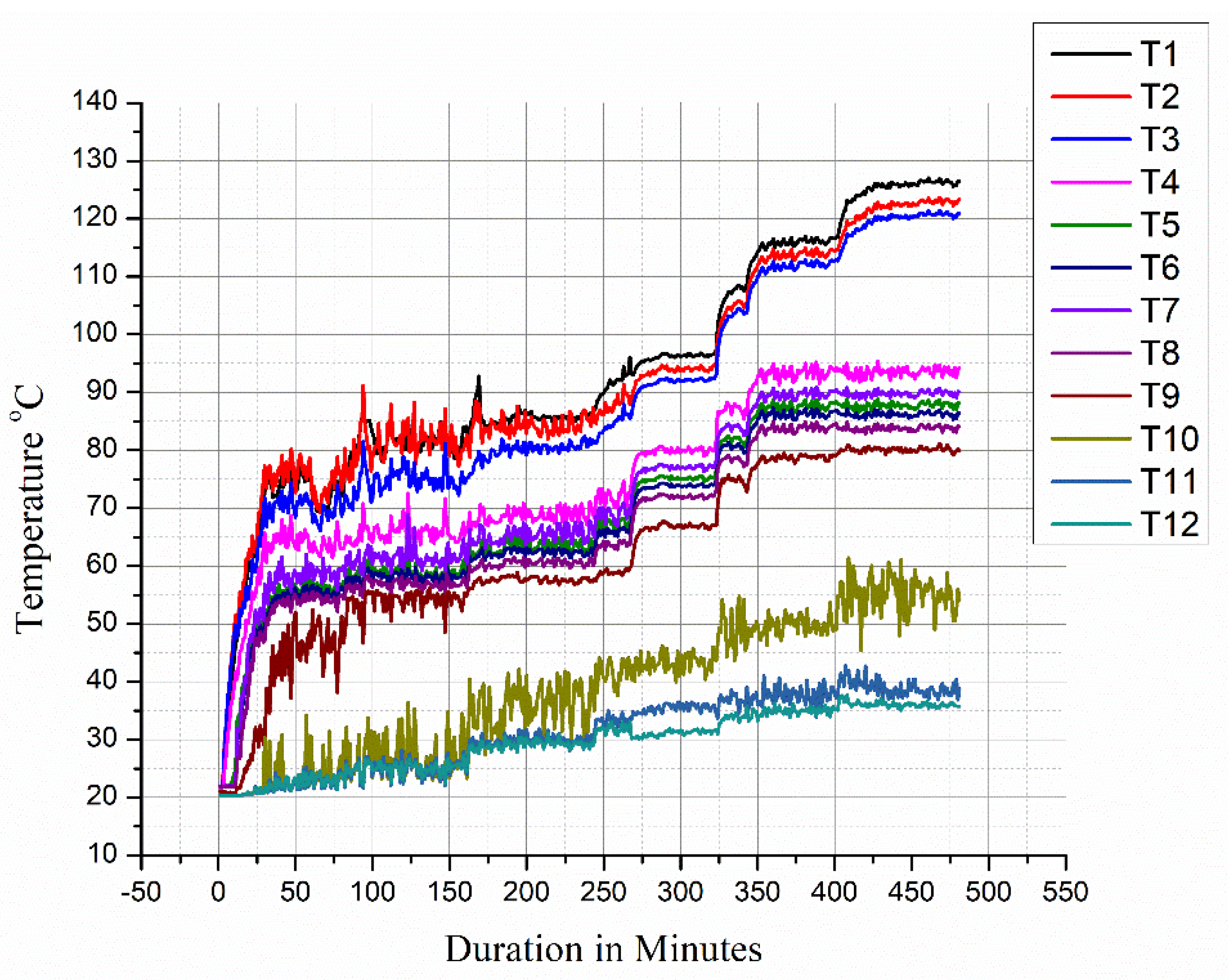
All the temperature readings are utilized for calculation only after attaining the steady-state condition. An illustration of thermocouples attaining steady-state condition is shown in
Figure 5 (corresponding to NUAS 90° orientation).
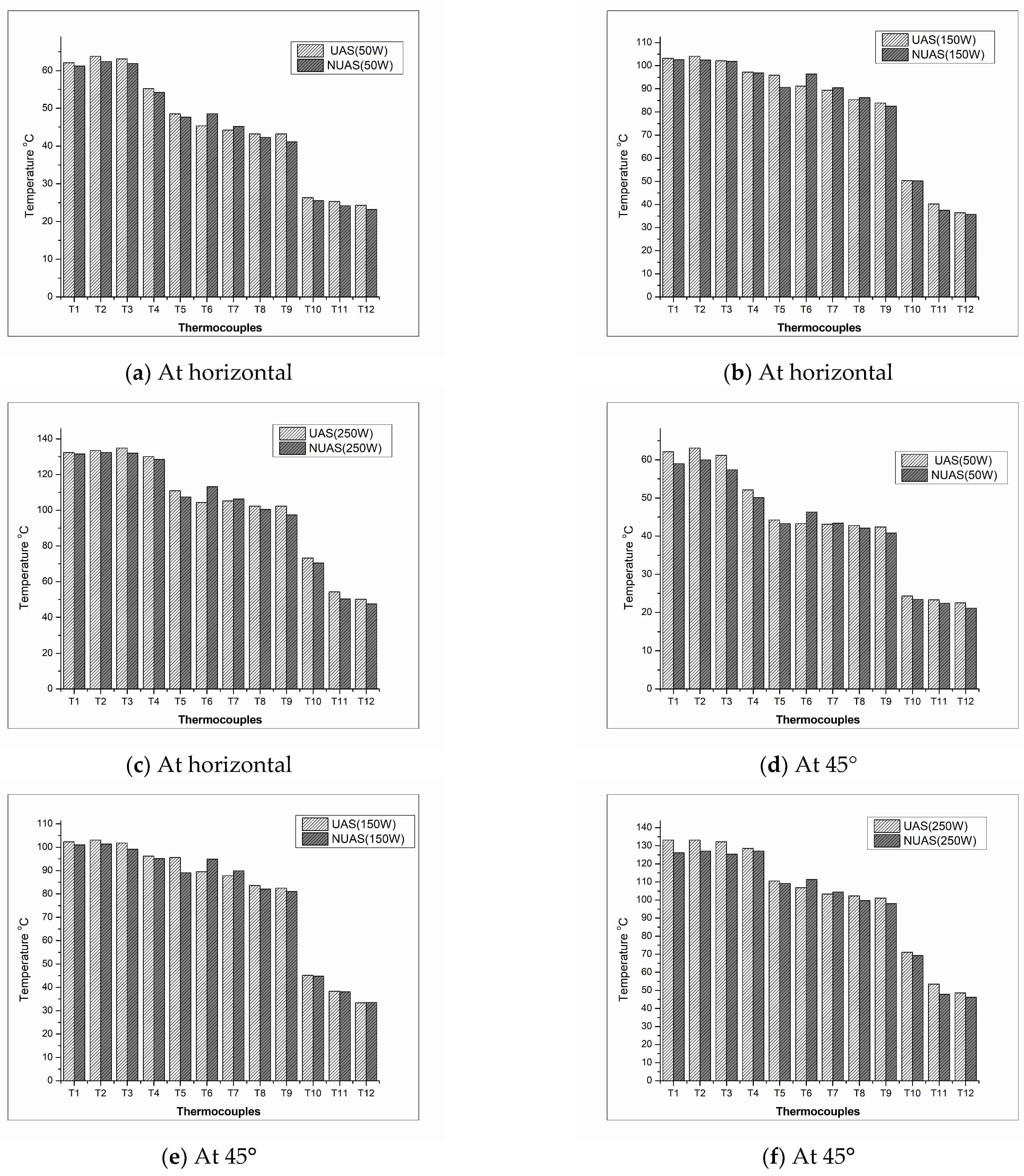
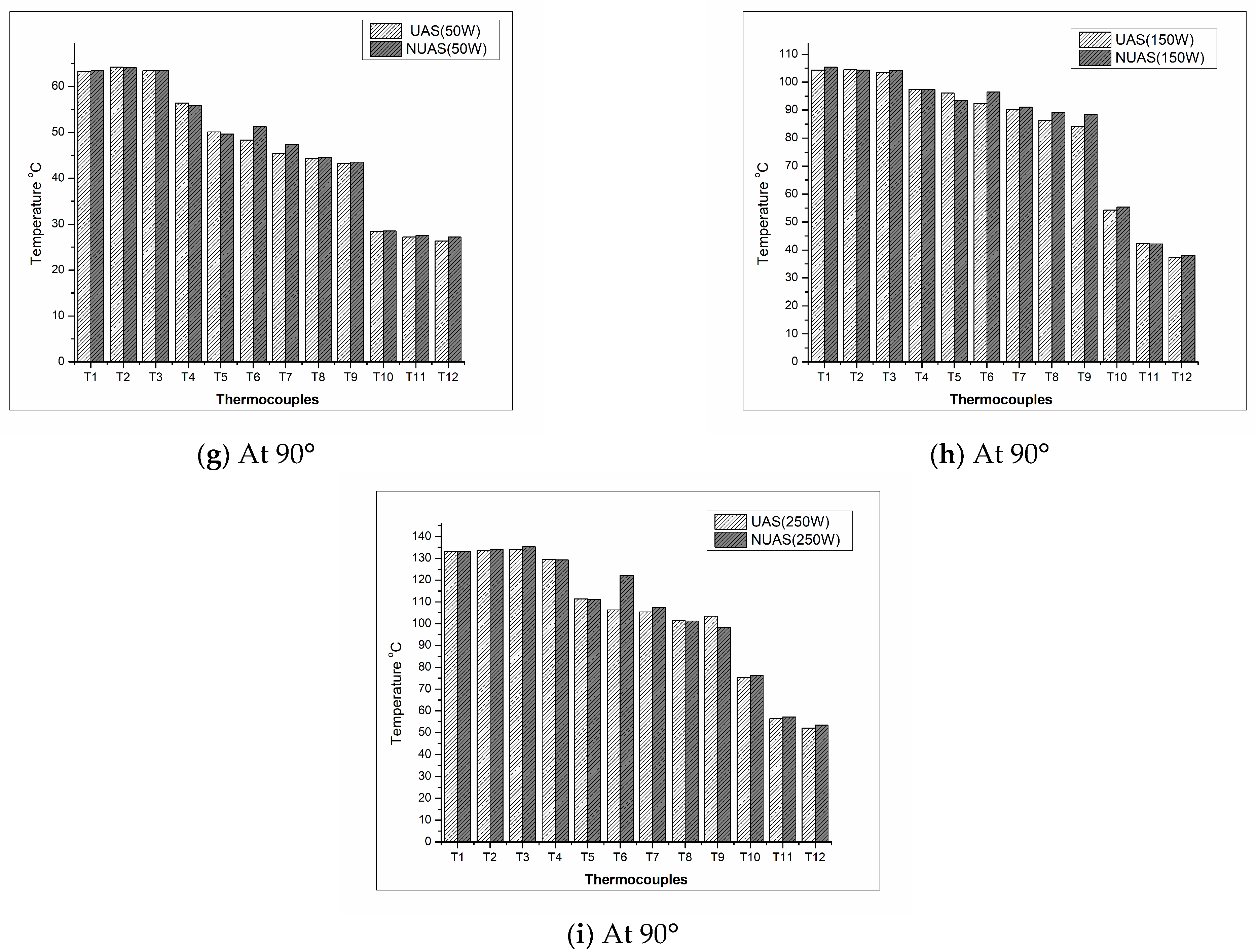
The temperature distributions for the different places in TPCT under various heat inputs, and with different setting angles are shown in
Figure 6. At the horizontal position, the NUAS induces lower temperature at the evaporator and condenser section due to lower thermal resistance. Moreover, at the C-D section, the thermal and hydraulic boundary layer is disrupted and redeveloped. This enhances the heat transfer [
28]. The accumulation of fluid attributed due to convergent shape increases the temperature near the T6 thermocouple (which is observed in all the heat inputs and orientations). This will increase the vapor pressure locally (before the convergent section) and improves the circulation of fluid between the evaporator and condenser section at a horizontal position. On the other hand, a pressure drop and acceleration are induced by the nozzle effect of the convergent section. The enhanced heat transfer is partially countered by an increased frictional factor since the fluid moves in a small diametrical path. When the accelerated fluid encounters the divergent section, the pressure begins to gain partially and temperature drops slightly owing to the sudden expansion and the induced turbulence in the flow. This improves the heat transfer rate and reduces the temperature near the condenser.
The average temperature at the evaporator in UAS TPCT was measured as 62 °C, whereas with NAUS it is about 59 °C at 50 W and 45° of setting angle as shown in
Figure 6d. Hence, the reduction was found about 5.31% with NUAS from UAS TPCT. At av45° orientation, the proposed C-D section lies in an inclined position and, therefore, when vapor tries to move perpendicularly upwards, direct obstruction of flow will not occur as it induced in the case of horizontal orientation. This results in less accumulation of fluid right before the T6 thermocouple when compared to other cases. When the vapor proportion is higher corresponding to higher heat input (250 W), the accumulation becomes much less as it can be seen in
Figure 6f with less temperature between NUAS and UAS at 45° corresponding to T6. Due to this, the heat transfer is further enhanced in a 45° orientation scenario as the thermal resistance is reduced significantly with the aid of gravity-driven fluid flow. On the other hand, NUAS at horizontal and vertical orientation during higher heat input experiences maximum temperature difference relative to UAS at T6 thermocouple which indicates higher fluid accumulation. As a whole, better fluid circulation, less fluid accumulation, reduced thermal resistance makes the NUAS at 45° orientation transfer more heat. However, in this case, the nozzle and the diffuser effect will not be as prominent as in the case of horizontal and vertical orientation because the vapor motion direction and the axis of the TPCT deviate by the incorporated tilt angle. And their cumulative influence on heat transfer augmentation requires more thermodynamic parameters to consider and involves complex assessment.
At 90° or vertical orientation, the nozzle and diffuser effect become promising at elevated temperature. However, in this case, the convergent section results in maximum accumulation of fluid as T6 temperature is maximum for 90° orientation. Further, the thermal resistance of the evaporator section is higher owing to the complete liquid phase existing at the bottom of TPCT. This is marked by the higher temperature in T1, T2, T3 at 90° when compared to 45° and horizontal orientation. The performance of NUAS at 90° is poorer than UAS as marked by increased temperature in almost most thermocouples across various heat inputs. This is attributed to the introduction of the C-D section that hinders the effective utilization of gravity assistance in enhancing the fluid flow circulation. Furthermore, the C-D section affects the return flow of condensed fluid to the evaporator since the divergent section acts as a convergent section while returning. This will completely obstruct the flow and induce a longer time to circulate the flow between the evaporator and condenser.
3.3. The Effect of Geometry Changes in the Adiabatic Section and Setting Angle Variation on the Heat Transfer Coefficient
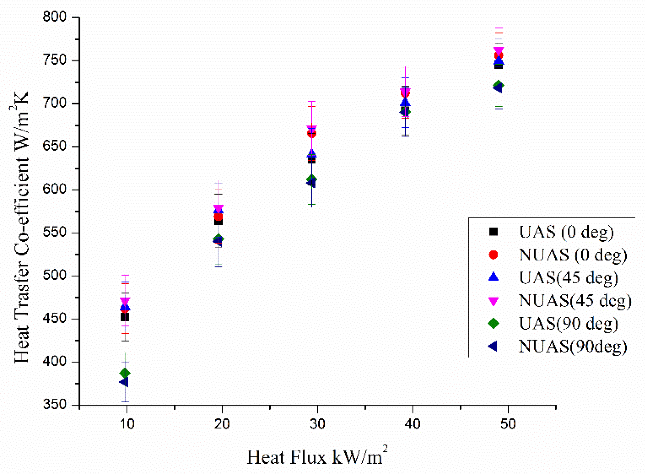
The heat transfer co-efficient variations are shown in
Figure 7 for the different setting angles on both UAS and NUAS. Normally, the heat transfer coefficient is found to be lower with lower heat flux and it increases with the increase of heat flux for test cases.
On comparing NUAS with UAS, the NUAS induced slightly better heat transfer co-efficient than the UAS in all the heat inputs test case and in horizontal as well as in 45° orientations. At horizontal orientation, the heat transfer coefficient with NUAS was found to be increased up to 2% and 1.46% with low and maximum heat fluxes, respectively, in comparison with the UAS case. Similar to this, 1.4% and 1.7% improved with low and high heat flux at 45° angle is obtained, respectively. However, at a 90° setting angle, the heat transfer coefficient was observed to be comparatively reduced. It was reported that the reduction of the heat transfer coefficient was observed up to 2.8% at low heat flux and 0.4% with high heat flux scenario with NUAS from UAS operation. The increment and decrement of this value are mainly due to variations in thermal resistances and pressure drop as influenced by geometrical changes while fluid accumulation and gravity assistance as influenced by orientation changes.
3.4. The Effect of Geometry Changes in the Adiabatic Section and Setting Angle Variation on Non-Dimensional Numbers
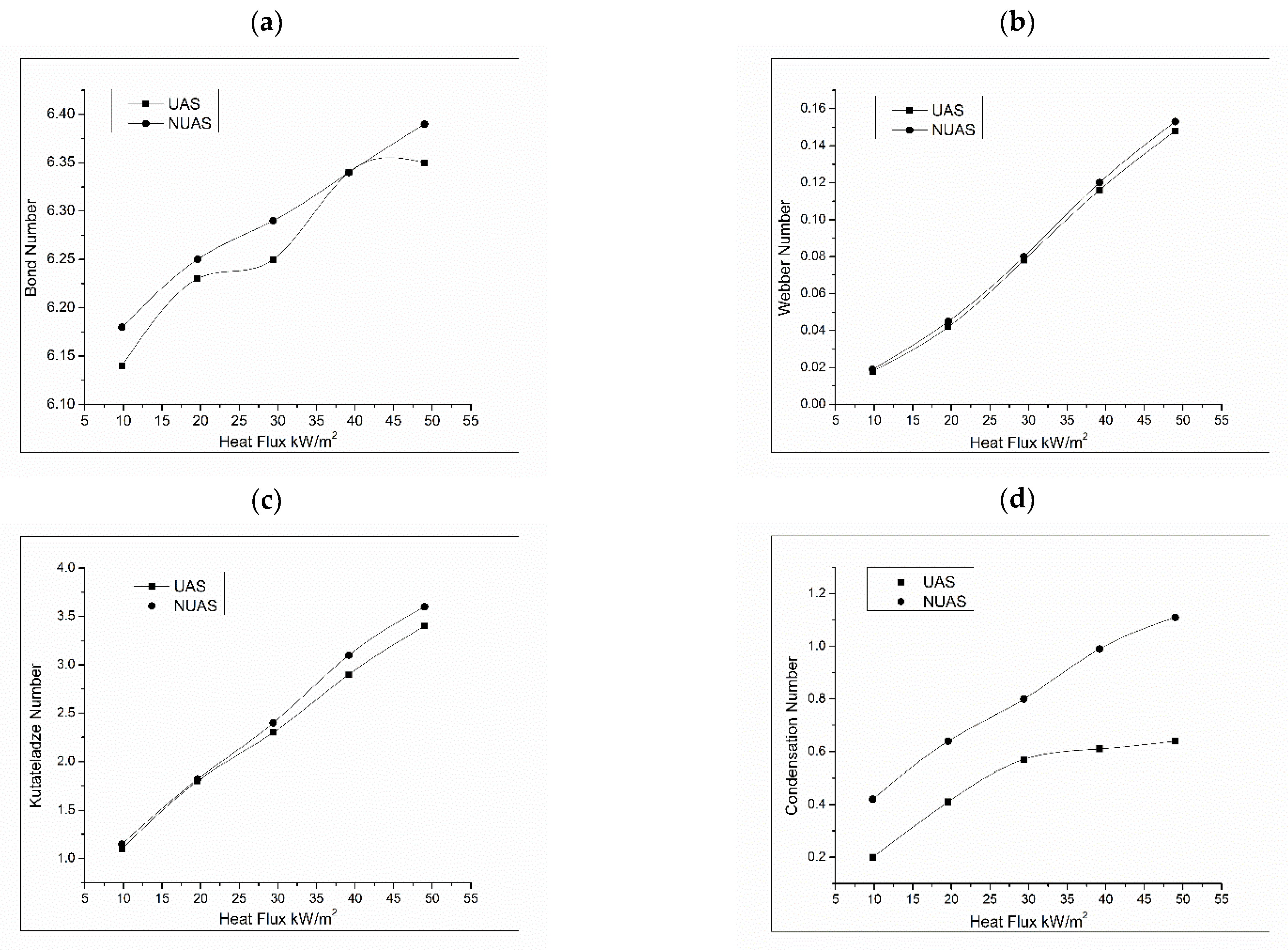
The BO number variation with different test cases is depicted in
Figure 8a. The BO number reveals the boiling enhancement in the evaporator section; it increased with the increase of heat flux in both NUAS and UAS TPCTs. Due to the increase in temperature, buoyancy and the convective heat transfer increases. Therefore, the boiling process is hastened with an increase in BO. The WE increase with the heat flux for both the TPCTs. This indicates that the counter-current interaction improves the heat flux and enhances heat transportation. The WE number was also found a little higher with NUAS TPCT shown in
Figure 8b; this indicates that the interaction between liquid and vapor or counter-current interaction is better in NUAS than UAS. Furthermore, it increased with the increase of heat fluxes in both TPCTs which enhanced better heat transportation. Similar to the WE number, the KU number also increased with the increase of heat fluxes shown in
Figure 8c, but this indicates better pool boiling characteristics induced by higher heat fluxes in both NUAS and UAS TPCTs. Furthermore, a higher KU number was noted with NUAS compared with UAS operation, which infers a better pool boiling phenomenon in NUAS TPCTs. The CO number variations based on different heat fluxes are provided in
Figure 8d.The CO number increased with the increase in heat fluxes and this indicates the amount of condensate returning to the evaporator. In the case of UAS, the condensate returning improved up to 30 kW/m
2, after which the curve does not witness any major improvement in terms of CO number. However, in the case of NUAS, the curve improved linearly up to the maximum heat fluxes and this indicates the amount of condensate return being improved heat fluxes. By analyzing the non-dimensional numbers, the heat transportation, interaction between liquid and vapor, pool boiling characteristics and condensate returning were found better with NUAS than the UAS TPCT operations.
The overall thermal performance of TPCT was increased up to 2% when the uniform adiabatic section was replaced by convergent and divergent sections. This was mainly induced by pressure drop and turbulence.


 ,
, 


