Article

The Impact of Active and Passive Thermal Management on the Energy Storage Efficiency of Metal Hydride Pairs Based Heat Storage

1
South African Institute for Advanced Materials Chemistry, University of the Western Cape, Private Bag X17, Bellville 7535, South Africa
2
Faculty of Electrical Engineering, Mechanical Engineering and Naval Architecture, University of Split, R Boskovica 32, 21000 Split, Croatia
*
Author to whom correspondence should be addressed.
Energies 2021, 14(11), 3006; https://doi.org/10.3390/en14113006
Submission received: 2 April 2021 / Revised: 12 May 2021 / Accepted: 19 May 2021 / Published: 22 May 2021
(This article belongs to the Section A5: Hydrogen Energy)

Abstract

:
Two-tank metal hydride pairs have gained tremendous interest in thermal energy storage systems for concentrating solar power plants or industrial waste heat recovery. Generally, the system’s performance depends on selecting and matching the metal hydride pairs and the thermal management adopted. In this study, the 2D mathematical modeling used to investigate the heat storage system’s performance under different thermal management techniques, including active and passive heat transfer techniques, is analyzed and discussed in detail. The change in the energy storage density, the specific power output, and the energy storage efficiency is studied under different heat transfer measures applied to the two tanks. The results showed that there is a trade-off between the energy storage density and the energy storage efficiency. The adoption of active heat transfer enhancement (convective heat transfer enhancement) leads to a high energy storage density of 670 MJ m−3 (close to the maximum theoretical value of 755.3 MJ m−3). In contrast, the energy storage efficiency decreases dramatically due to the increase in the pumping power. On the other hand, passive heat transfer techniques using the bed’s thermal conductivity enhancers provide a balance between the energy storage density (578 MJ m−3) and the energy efficiency (74%). The utilization of phase change material as an internal heat recovery medium leads to a further reduction in the heat storage performance indicators (142 MJ m−3 and 49%). Nevertheless, such a system combining thermochemical and latent heat storage, if properly optimized, can be promising for thermal energy storage applications.

Graphical Abstract

1. Introduction

The hydrogen absorption into and desorption from hydride materials are accompanied by a high heat release and consumption, respectively. This has made hydride materials desirable for various heat-related applications, such as heat pumps, heat transformation, and, more recently, heat storage for solar energy applications [1,2]. Among these hydride materials, Mg-based hydrides have stimulated worldwide interest in their utilization in hydrogen/heat storage and high-temperature fuel cell technologies. This is particularly true due to their relatively high hydrogen storage capacity (3.6–7.6 wt% and 110–150 kg-H2/m3) and the high heat of the reaction (60–80 kJ/mol-H2) [3,4]. As a result, their use in concentrated solar power (CSP) plants can improve performance in terms of energy storage density compared to the state-of-the-art two-tanks-based molten salts [5,6], one tank-thermocline [7,8], and latent heat phase change materials [9,10], although the economic analysis shows that metal hydrides are more expensive [11,12].
Few studies on the design and optimization of Mg hydride material-based thermal energy storage for CSP plants have been reported, not only experimentally but also theoretically [2,3,4,11,12,13,14,15,16,17,18,19,20,21,22,23,24]. Nyallang et al. [2] proposed a procedure for choosing metal hydrides pairs for thermal energy storage systems on the basis of energy storage density and efficiency criteria. The findings showed that the coupling of Mg-based hydrides with the most commercially-available low-temperature hydrides, such as LaNi5, could lead to an energy storage efficiency of 0.7–0.8, with an energy storage density reaching up to 1 GJ·m−3. In addition, during the heat discharging process, the average output temperature of the heat transfer fluid (HTF) could be enhanced by 25 °C, which is essential for the power plant’s exergetic efficiency located downstream of the thermal energy storage system. Reiser et al. [3] experimentally prepared and characterized Mg-based hydride materials for heat storage applications. The results showed that these materials are stable within the temperature range 250–550 °C, with thermal energy densities reaching up to 2.257 MJ·kg−1. Bogdanovic et al. [4] experimentally reported the performance of a pilot process steam generator equipped with a Mg-based hydride heat storage device. The heat storage system provided 9.08 kWh of heating output at 370 °C, with an energy efficiency of up to 0.796. Corgnale et al. [12] reported a screening procedure of suitable high-temperature metal hydrides for thermal energy applications. The screening procedure included a techno-economic analysis that analyzed the cost, the energy storage density, and the exergetic efficiency of these materials. The results showed that TiH2, CaH2, and NaMgH3 showed a desirability for CSP plants, since their operating temperature is above 600 °C and their volumetric energy density exceeds 25 kWh/m3. Sekhar et al. [13] reported experimental tests on a heat storage reactor filled with Mg–30% MmNi4. They investigated the effects of operating conditions on key performance indicators such as hydrogen capacity and energy storage efficiency. The results showed that at a fixed absorption temperature (150 °C), the increase in hydrogen pressure from 10 to 30 bars augments the thermal energy storage efficiency, which increases from 0.5 to 0.74, respectively. Given its high energy density of ~2.9 MJ/kg and high operating temperature (580–600 °C), the perovskite-type hydride NaMgH3 showed great potential as a solar energy material [14]. In addition, the hydride showed minimum kinetic degradation during a cycling stability study. Fang et al. [15] proposed and tested a proof-of-concept thermal battery based on a metal hydrides pair. The pair consisted of 50 g of a Mg-based hydride composite (MgH2 + TiMn1.5 + 5 wt%ENG) with 150 g of TiMn1.5V0.62. The results showed that the total cooling and heating energies were 13.6 kWh and 35.4 kWh, respectively. This corresponds to a coefficient of performance (COP) of 0.384 for cooling, which is close to the theoretical one. Paskevicius et al. [16] proposed a prototype comprising of a metal hydride bed (19 g of MgH2) and a 2250 cm3 H2 bottle for TES in concentrated solar power plants. The results showed that the hydride was thermally cycled at 420 °C, with a limited H2 capacity loss. Moreover, for very small-scale applications, there are many issues, such as powder agglomeration and heat loss to the environment, thereby decreasing the energy utilization of the storage system. Poupin et al. [17] experimentally investigated a high-temperature (HT) thermal battery pair with a low-temperature (LT) metal hydride for solar-related power plants. The battery consisted of 40.7 g of 2 Mg–Fe for HT heat charging/discharging and 85.2 g of a TiMn1.5 alloy 5800 for the hydrogen storage medium. The results showed that a maximum energy storage density of 1.488 MJ/kg was achieved at a temperature of 520 °C. In addition, the effect of the thermal cycling and volumes of the LT and HT reactors on the thermal energy storage performance was emphasized and discussed. Bogdanovic et al. [18] proposed a TES based on a MgH2/AB2 (code 5800) metal hydride pair. The system could exchange a maximum of 69 g of H2 between the hydrides beds. The system consisted of 1.054 kg of MgH2 paired with 5.9 kg of an AB2-type hydride (Ti0.98Zr0.02Fe0.09Cr0.05Mn1.2), which could simultaneously produce ice and high-temperature heat. The results showed that the magnesium container produced 0.64 kWh of heat after absorbing 59 g of H2 after 3 h. In the meantime, in the low-temperature metal hydride, the formation of 1.9 kg of ice was observed, which accounts for 0.18 kWh of cooling effect (28% of the heating effect). Ward et al. [19] compared two metal hydrides pairs, such as NaMgH2F/Na3AlH6 and NaMgH3/NaAlH4, for heat storage systems. It was shown that the installed cost of a heat storage system integrating the former pair was 11% lower than that integrating the latter pair, which is <30 $/kWh. Moreover, the energetic efficiency was increased by 5%. Bao and Yuan [20] reported the performance of metal hydride-based heat storage systems adopting multi-step operating conditions. The findings showed that the adoption of this operating condition allows for a constant outlet temperature of the heat transfer fluid during the heat discharging process. Bao [21] investigated the effect of heat-transfer enhancement measures on the performance of a magnesium hydride-based high-temperature thermochemical heat storage. These measures included extended surfaces (fins) and thermal conductivity augmentation based on compacted metal hydride-graphite. The results showed that the latter provides uniform temperature distribution inside the reactor; thus, it should be recommended for metal hydride-based heat storage applications. d’Entremont et al. [22] numerically investigated the performance of the metal hydrides pair NaMgH2F/TiCr1.6Mn0.2 for heat storage. The results showed that this thermal energy storage system could achieve an output energy density of 226 kWh/m3, nine times the DOE SunShot target, with moderate temperature and pressure swings. Besides, simulations indicate that passive heat-transfer enhancement strategies can significantly improve performance. Malleswararao et al. [23] carried out the performance prediction of a metal hydride pair for TES using a 3D model simulation into COMSOL. The pair was made of Mg2Ni/LaNi5 hydrides, which was selected using a thermodynamic compatibility check. The findings showed that the energy storage density of 156 kWh/m3 at an energy storage efficiency of 89.4% was achieved. Mellouli et al. [24] conducted a numerical analysis of a heat storage system based on metal hydrides pair made of Mg2FeH6/Na3AlH6. The results demonstrated that under the given operating conditions, the heat storage could deliver an energy density of 90 kWh/m3, with a 96% energy storage efficiency.
From the studies mentioned above, it is clear that Mg-based hydrides in heat storage applications suffer from two undeniable challenges, namely, slow intrinsic kinetics and a thermal management based on a tank design and optimization viewpoints. While the use of catalysts and the pre-processing of hydride powder by mechano-synthesis using high-energy reactive ball milling (HRBM) can considerably alleviate the former, the latter remains a problem. Regardless of the intensive efforts given to the design of a metal hydride tank, the rate at which these hydride materials store/restore hydrogen depends strongly on the system’s configuration, the operating conditions in terms of pressure and temperature, and, more importantly, upon the heat and mass transfer abilities [25]. Numerous studies have discussed the effects of heat-transfer enhancement methods on the performance behavior of metal hydride reactors. According to this review [26] and references therein, the heat-transfer-enhancement measures consist of the following two techniques: passive and active. Passive heat-transfer-enhancement techniques comprise the insertion of inert materials that have a high intrinsic thermal conductivity (e.g., extended surfaces (fins), meshes, or expended natural graphite (ENG) compacts). As can be seen, the passive heat transfer measures consist mainly of thermal conductivity augmentation and represent 43% of the heat transfer mechanisms studied in the literature. Yang et al. [27] numerically investigated the effect of heat-transfer-enhancement measures in a metal hydride reactor for heat pumps. They discussed the performance of three reactors adopting a passive heat-transfer-enhancement using aluminum foam or highly compacted metal hydrides. The simulation results showed that for metal hydride heat pumps utilizing the heat-transfer enhancement mentioned above, the performance’s coefficient slightly reduces, while the specific heating power remarkably increases. Several experimental studies [28,29,30,31,32,33] have shown that effective thermal conductivity greatly enhanced the hydrogen flow transfer between coupled beds. This thermal conductivity enhancement was shown to be the most decisive aspect in the overall heat transfer coefficient [34].
On the other hand, the active heat transfer techniques consist of any method that improves the heat transfer fluid’s convective heat transfer coefficient. This method generally applies to cooling/heating tubes, reactor jackets, and shell-tube heat exchangers. It should also be mentioned that the active heat transfer techniques come at the cost of an external energy input (e.g. pump, fan, compressor, etc.) which is needed to displace the heat transfer fluid. Therefore, based on that review [26], the forced convection is highly utilized to reduce the hydrogen absorption/desorption time in hydrogen storage applications. However, there is no evidence of its effect on the energetic efficiency of the hydride reactors.
Generally, in CSP plants, the two-tank-based heat storage systems consist of two metal hydrides operating within different temperature ranges. Therefore, its energy storage efficiency depends on the selection of the metal hydride pair [2,12] and the thermal management adoption. While the high-temperature metal hydride bed is always connected to the high-temperature heat source using active heat management, the low-temperature metal hydride may adopt different thermal management techniques to remove/add heat during the heat charging/discharging process. As a result, there is a difference in the heat transfer conditions applied to the two-tank energy storage systems, which can significantly affect the system performance. However, there are no studies investigating the effects of such a mismatch between the thermal management techniques on the system’s performance. The present study aims to numerically investigate the effect of the adoption of various thermal management techniques on the energy storage efficiency of the thermal energy storage system. These techniques include passive (bed thermal conductivity augmentation, natural convection, phase change materials-based heat recovery/input) and active (forced convection) heat-transfer enhancements.

2. Mathematical Model

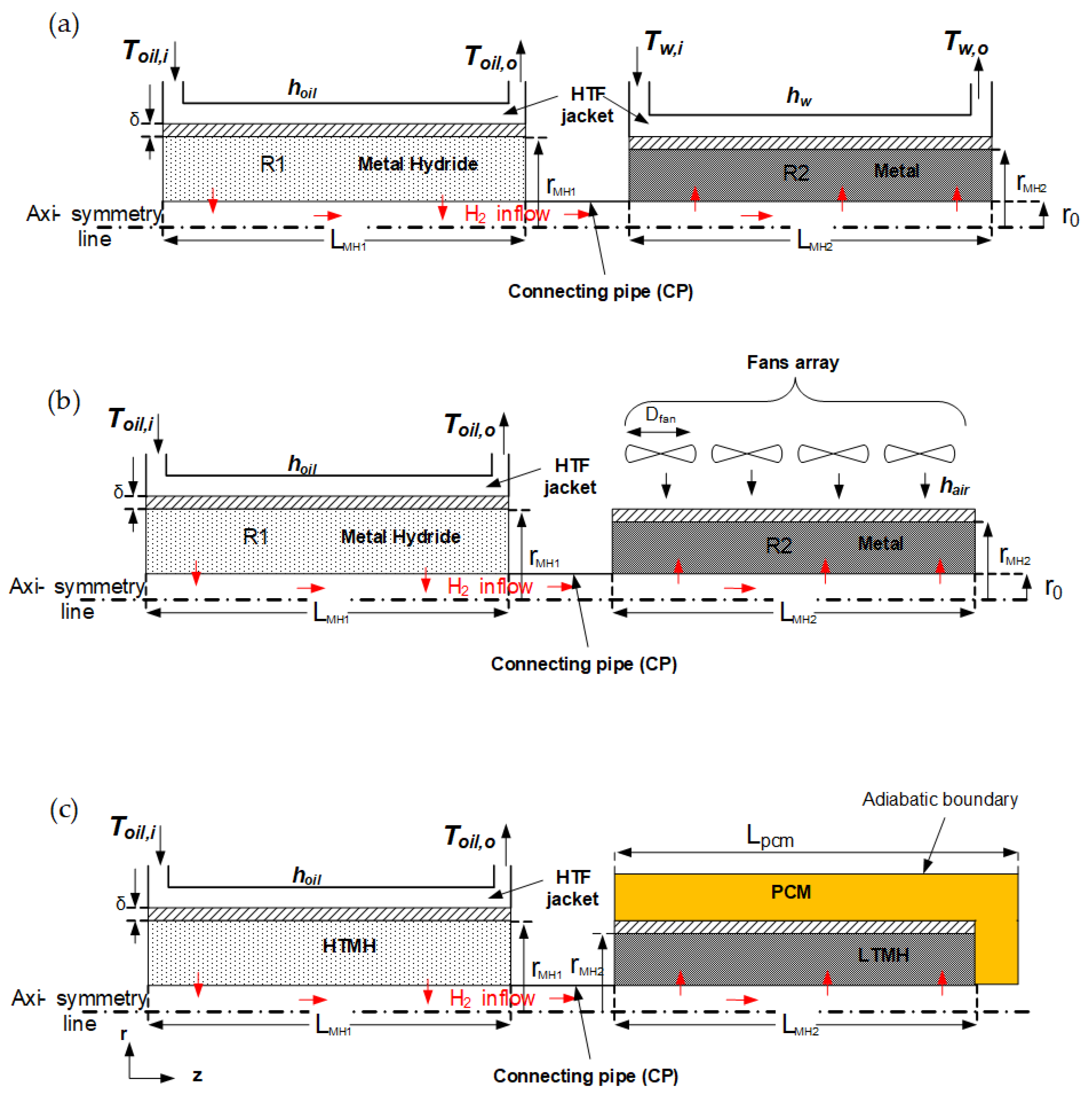
2.1. Problem Description

The performance of two-tank metal-hydride heat storage systems for CSP plants depends on the matching of the intrinsic thermodynamic properties of the hydrides, the reactor configuration, and the heat transfer measures adopted. A CSP plant, a physical description of which is depicted in Figure 1, generally consists of the following three blocks: the solar energy collector, the heat storage system, and the power block. The heat storage system studied here comprises two metal hydride beds. One bed (tagged for simplicity as R1) is filled with a high-temperature saturated metal hydride (HTMH) for heat storage. In contrast, R2 is filled with a low-temperature metal precursor (LTMH) for hydrogen storage. A high-temperature heat transfer fluid (HTF) collects the solar heat from the parabolic trough collectors and discharges it through the HTMH, with a convective heat transfer coefficient of h0. The maximum allowable temperature range governs the selection of the HTF for such an application. There is a variety of HTFs for concentrating solar power applications (parabolic troughs). However, the maximum temperature achievable using these HTF-based oils is less than 425 °C, e.g., Therminol VP-1 [6] and Dowtherm A [21,25]. On the other hand, the selection of an HTMH should be in line with the HTF’s temperature range, i.e., the HTMH should desorb hydrogen at the HTF’s operating temperature at an acceptable rate without deteriorating the material. Mg-based hydride materials generally fit this range of operating temperature (300–400 °C). The low-temperature metal precursor is another essential component of the system. Although the experiments show that it possesses relatively fast kinetics, the overall hydrogen storage rate may depend on the heat transfer measures.
From Figure 1, the heat storage system can be devised in different configurations, taking into account the various thermal management techniques, while maintaining a mismatch between the overall heat transfer coefficient of the reactor beds. In the first configuration (Config. 1), a low-temperature metal precursor (LTMH) bed (R2) is exposed to the environment, and heat is provided or extracted by natural convection, using air as an HTF, at a heat transfer coefficient h1. In the second configuration (Config. 2), R2 is subjected to forced-air convection. In the third configuration (Config. 3), water is used as an HTF in a forced convection jacket. The design of configuration 4 (Config. 4) assumes that each bed’s convective heat transfer is equal to h1 = h0, and that the thermal conductivity of each bed is equally enhanced by the addition of graphite in the same proportion. This configuration is an idealized design where the heat transfer conditions in the coupled beds are matched, which usually can be difficult to implement in practice. During the heat discharging step, waste heat from the condenser of the power plant can be used to heat up an LTMH bed. In such a case, the reaction heat of an LTMH does not affect the overall energy efficiency of the system [12,22]. In the fifth configuration (Config. 5), an LTMH bed is embedded in a jacket containing a phase change material (PCM). This configuration has been proposed by Mellouli et al. [35]. Moreover, it is found that the heat stored in the phase change material can be reutilized for H2 desorption in the case of heat discharging, which can significantly improve the energy efficiency [34,35,36,37] of the system, as will be discussed hereafter. In these different configuration designs, we can see a mismatch between the heat exchangers’ heat transfer coefficient of the beds. For example, the ratio between h1 and h0 (rh = h1/h0) is expected to vary from 0 to a value > 1. When air is used as an HTF, the heat transfer coefficient h1 can vary between 1 and 100 W m−2 K−1 for natural to forced convection, respectively. Taking these values of h1 into account, rh varies in the range of 0–1. On the other hand, forced convection using water can lead to rh > 1, given the better water properties as an HTF compared to an oil-based HTF.

2.2. Computational Model

A 2D axis-symmetry mathematical model is established and analyzed. Figure 2 portrays the computational volumes of the three configurations (Config. 3, 2, 5) mentioned above. A computational model consists of a coupled cylindrical tubular reactor connected by a hydrogen pipe with a radius of r0. The material is in the annulus (rMH-r0), and the heat is added/removed through a reactor shell of a fixed thickness (δ = 2 mm). The length of each bed is equally fixed as LMH1 = LMH1 = 450 mm. For configurations 1, 2, and 3, the convective heat transfer coefficient is calculated using the procedure given in the subsection, “Convective heat transfer coefficient calculation.” In configuration 5, the jacket of an LTMH is filled with a PCM, and the heat transfer condition of the PCM’s outside shell is assumed to be adiabatic [37].

2.3. Governing Equations

The multi-physics mathematical equations, taken from our previous studies [2,38,39,40], are utilized. The following hypotheses are made:
  • The thermal equilibrium between the H2 and the metal hydride is assumed;
  • The intrinsic physical properties of the hydrides are constant during each step of the thermal energy storage;
  • The jacket is perfectly insulated (adiabatic wall);
  • The radiative heat transfer is neglected;
  • Hydrogen is considered to be an ideal gas;
  • The hysteresis phenomenon is not considered in the equilibrium pressure of metal hydrides.
Energy balance
The local bed temperature is computed using the following energy equation:
ρ C p e f f T t + · ρ g C p g V T = λ e f f 2 T + 1 ε M g ρ M H w t d α d t Δ H
where the effective heat capacity and the thermal conductivity are given, respectively, as follows:
ρ C p e f f = ε ρ g C p g + 1 ε ρ M H C p M H
λ e f f = ε λ g + 1 ε λ M H
If a fraction fENG of inert material, such as expanded natural graphite (ENG), is added to a metal hydride bed in order to improve the overall thermal conductivity, the effective heat capacity and thermal conductivity read as follows [37]:
ρ C p e f f = 1 f E N G ε ρ g C p g + 1 f E N G 1 ε ρ M H C p M H + f E N G ρ E N G C p E N G
λ e f f = 1 f E N G ε λ g + 1 f E N G 1 ε λ M H + f E N G λ M H
In Config. 5, the energy balance of the phase change is taken from a Mellouli et al. [33] model and expressed, with an additional few assumptions, as follows:
  • The thermo-physical properties of the PCMs are assumed to be constant;
  • The PCM’s latent heat is independent of the temperature;
  • The effect of natural convection is negligible;
ρ m i x C p T p c m T p c m t = λ m i x 2 T p c m
where the apparent heat capacity of the composite is defined as follows:
ρ m i x C p T = ρ p c m , s C p , s 1 f p c m + ρ p c m , l C p , l f p c m + ρ p c m , s Δ H p c m d f p c m T p c m d T p c m  
The liquid fraction is defined as follows:
f p c m = 0 T p c m < T m 1 T p c m > T m + Δ T t r T p c m T m Δ T t r T m < T p c m < T m + Δ T t r
The field temperature of the reactor’s wall is formulated as follows, assuming its density and thermal capacity is temperature-independent:
ρ C p w a l l T w a l l t = λ w a l l 2 T w a l l
Mass balance
The variation of hydrogen gas in the porous bed of each reactor is given by the following:
ε ρ g t + · ρ g V = 1 ε ρ M H w t d α d t
where the hydrogen speed in the porous medium is calculated using Darcy’s law, as follows:
V = K e f f μ g p
The Kozeny–Carman formulation describes the permeability Keff as follows [41]:
K e f f = ε 3 d p 2 150 1 ε 2
The permeability depends on the particle size of the hydrides. In fully activated hydride materials, the diameter of the particles is in the range of 10–100 µm. As a result, the permeability may be in the range of 3.3 × 10⁻¹³–3.3 × 10⁻¹¹ m2, assuming a porosity of 0.5. However, for this study we fixed the permeability to 1.3 × 10⁻¹² m2.
The hydrogen speed in the connecting pipe is as follows:
t · ρ g V + · ρ g V · V = p + μ g 2 V
The following first-order kinetic model is used to represent the reaction kinetics of an LTMH (LaNi5) [39,42] and an HTMH (Mg2Ni) [40,43]:
Absorption:
d α d t = k a exp E a R T   ln p p e q 1 α
Desorption:
d α d t = k d exp E d R T p p e q p e q α
The equilibrium pressure is expressed as follows [40,43]:
ln p e q p 0 = Δ H R T Δ S R
Boundary conditions
There is a continuity of heat transfer at the interfaces of the metal hydride and the reactor wall, the reactor wall and the heat transfer fluid/air, and the reactor wall and the phase change material (Config. 5), as follows:
λ e f f T · n = λ w a l l T w a l l · n
λ w a l l T w a l l · n = h H T F / a i r T H T F / a i r T w a l l · n
λ w a l l T w a l l · n = λ p c m T p c m · n
The hydrogen flow continuity across the interface of the MH (R1 or R2) and the connecting pipe (CP) is as follows:
n · p R 1 , R 2 = n · p C P
The adiabatic (axis-symmetry) boundary conditions are as follows:
T r r = 0 = 0 ,   p r r = 0 = 0 , p r r = r M H = 0
Initial and operating conditions
When t = 0, the uniform beds temperature is THTMH = TLTMH = T0 = 20 °C, the uniform initial H2 pressure is PHTMH = PHTMH = P0 = 1.96 bar, αHTMH = 1 (fully hydrided), αLTMH = 0 (metal precursor), and f = 0 (PCM is in solid state for Config. 5).
A full cycle consists of three steps, namely, the heat charging, heat storage, and heat discharging processes.
During heat charging (0 < t < tc = 3 h), the R1 bed is heated to Th = 623 K to increase the hydrogen pressure to up to 9 bar (the equilibrium pressure of Mg2NiH4 is at 623 K), while the R2 bed is cooled at Tl = 293 K. During the heat storage and heat discharging steps (3 h < t < ts = 6.5 h), the R2 bed is heated up to Th = 353 K to increase the pressure to ~8 bar, while the R1 bed is cooled to Tl = 573 K (the minimum temperature for H2 absorption in Mg-based materials) to allow for an equilibrium pressure difference.

2.4. Heat Transfer Calculation

In Configurations. 1 and 2, the LTMH bed is surrounded by air. Given the low thermal conductivity of air at an ambient pressure, the convective heat transfer coefficient   h ¯ is expected to be lower. h ¯ is derived from the expression of the Nusselt number N u ¯ :
h ¯ = k d h N u ¯
where k is the thermal conductivity of the HTF, and dh is the hydraulic diameter.

2.4.1. Forced Convection

The average Nu number for the forced convection around a cylindrical object, where the heat transfer fluid’s direction is perpendicular to the axis of the latter object (crossflow), is given as follows [44]:
N u ¯ = 0.3 + 0.62 R e D 1 / 2 P r 1 / 3 1 + 0.4 P r 2 / 3 1 / 4 1 + R e D 282000 5 / 8 4 / 5
Note that the properties are evaluated at the film temperature, T f = T + T s / 2 .
For a cooling jacket using water/oil as the heat transfer fluid, the following expressions are used to calculate the convective heat transfer coefficient [44]:
For   3000 < R e D < 10 , 000
N u ¯ = 0.86 d o / d i 0.16 × 0.116 1 + d h L 2 / 3 R e D 2 / 3 125 P r 1 / 3
For   R e D > 10 , 000
N u ¯ = 0.86 d o / d i 0.16 × 0.023 1 + d h L 0.7 R e D 0.8 P r 1 / 3
The Reynolds number is given as follows:   R e D = V d h / ν where V is the HTF’s velocity, and ν is the kinematic viscosity. Moreover, the inner and outer jacket diameters, di and do, are linked to the hydraulic diameter dh by the following relation: dh = dodi.

2.4.2. Free Convection

The following expression is recommended for the calculation of Nu [44]:
N u ¯ D = 0.6 + 0.387 R a D 1 / 6 1 + 0.559 / P r 9 / 16 8 / 27 2 ,   R a D < 10 12
The Rayleigh number reads as follows:
R a D = g β T s T D 3 ν α
where the average temperature-dependent physical quantities are used as follows: α = 32.8 × 10⁻⁶ m2·s−1, β = 2.725 × 10⁻³ K−1, and g = 9.81 m·s−2. The calculation of the Rayleigh number, given an LTMH bed diameter of 0.03 m and an operating temperature range of 40–80 °C, results in values ranging from 3.8 to 5.8 × 10⁴. Using Equation (23), the Nusselt number varies in the narrow range of 6.07–6.736. As a result, a convective heat transfer coefficient of 6–7 W·m−2·K−1 can be obtained.

2.5. Fan and Pumping Powers

There are two main auxiliary components needed for a smooth operation of TES, namely pumps, fans, and heaters for the low temperature metal hydrides. For all of the configurations discussed in this study, fans and pumps are used to provide the motion of the HTF, air and water in R2 or oil in R1. The motion of the HTF is always entailed by an energy (work) penalty, which should be taken into consideration when calculating the energy efficiency of the system, as follows:
W w / o i l = m ˙ w / o i l   Δ P ρ w / o i l η p u m p t c y c l e
Δ P = C f L M H d h + K 1 · ρ w / o i l u w / o i l 2 2
where Cf is the friction factor and K1 = 1.5 is the additional pressure loss factor due to the exit of the HTF from the channel flow [45]. The aerodynamic kinetic energy of the air induced by the fan is calculated as follows:
W f a n = π D f a n 2 ρ a i r u a i r 3 8 η m
where η m / p u m p is the fan driving motor or pump efficiency. A value of 0.8 is assumed throughout this work.

2.6. Performance Evaluation

The following three key performance criteria can be utilized to assess the viability of the heat storage system [2]:
  • The volumetric heat storage density is as follows:
Q c / d = m ˙ f C p , f 0 t c , d T f , i T f , o d t V s
  • The heat discharging specific power is as follows:
Q ˙ d = m ˙ f C p , f Δ T ¯ m H T M H
  • The energy storage efficiency is as follows:
η = Q d Q c + W
where Vs is the total volume of the thermal energy storage components, tc/d is the heat charging/discharging time, and mHTMH is the weight of the HTMH. W in Equation (33) accounts for the energy necessary to displace the HTF. In addition, note that the LTMH’s heat of reaction has not been included in Equation (33), since from now on we will assume that this heat is readily available, either from the solar field or from the condenser of the power block. However, for rigorous analysis, this heat should be included.

3. Results and Discussion

3.1. Numerical Setting and Model Validation

The finite element method (FEM) software package COMSOL 3.5a has been utilized to solve the multi-physics governing equations. A MATLAB environment has been used to post-process the simulation results, by plotting the surface plots of temperature, reacted reaction fields, and calculating the key performance criteria. Figure 3 describes the flowchart of the model setting and solving in COMSOL-MATLAB. Three modules have been selected. Under the Earth Science Module, the heat transfer application mode (eshcc) was chosen to solve Equations (1), (6), and (9). Then, the momentum transport using a laminar flow (chns) and a porous media flow (chdl) under the Chemical Engineering Module was chosen to solve Equations (11) and (13), respectively. Finally, the reacted fraction and PCM melting fraction were set under the COMSOL Multiphysics module, using the PDE-coefficient-form application mode. The direct linear solver UMFPACK was utilized for solving the model. The relative and absolute tolerances on the calculated variables were 10−3 and 10−4, respectively, to assure convergence. Table 1 and Table 2 list the simulation parameters consisting of the metal hydrides’ thermophysical properties, the heat transfer fluids, and the reactors’ (R1 and R2) design. The unstructured mesh of the computational volume was sufficiently refined to balance the results accuracy and the computational time.
To illustrate the mesh size independence, Figure 4 depicts the effect of mesh size on the temperature and the H2 concentration profile of the Mg2NiH4 bed. As can be seen, there is a minute variation in the bed temperature and the hydrogen concentration with the mesh size varying between 4270–5734 elements (the curves coincide). Moreover, the performance indicators, such as discharging energy density (proportional to the integral of bed temperature over time), varied within an absolute error of 0.3%. A mesh size of 5219 elements was chosen for the subsequent part of the discussion.
A two-step model validation has been undertaken. In the first step, the metal hydride reactor’s numerical model was compared to the micro-scale (1 g) experimental data given by the authors of [41]. In the second step, the equations governing the PCM’s behavior were validated using the experimental data given by the authors of [46]. For the sake of brevity, the reader is referred to our previous work (See Figure 6, herein) [39].

3.2. Heat Transfer Versus Pumping HTF

This section investigates the relation between the heat transfer enhancement, and the pumping and blower (fan) powers in the different studied configurations. As is well-known from the fundamental viewpoint of heat and mass transfer, increasing the mass flow rate of the HTF increases the coefficient of convective heat transfer at the expense of the pumping power (since the pumping and fan power display a cubic-power dependence on mass flow rate (velocity)). Figure 5 depicts such a relation given the nature of the HTF. As shown in Figure 5a, water provides a high heat transfer coefficient compared to synthetic oil for a given mass flowrate/hydraulic diameter in the case of turbulent flow (forced convection). Given the operating conditions chosen here, the heat transfer coefficient in R1 (oil) can be as high as 6000 W·m−2·K−1, while in R2 (water), it reaches ~12,000 W·m−2·K−1 at a 1 kg s−1 mass flow rate. Moreover, these values can also be high in the laminar flow regime (flat line), reaching ~157 and 926 W·m−2·K−1 for oil and water, respectively. These coefficients of convective heat transfer are accompanied by a maximum penalty of 11.5 and 9.98 W pumping power for oil and water, respectively.
In the case of forced convection using air as the HTF, the situation is quite overwhelming (See Figure 5b). First, the heat convection coefficient does not exceed 100 W·m−2·K−1, even with a high operational velocity of up to 30 m·s−1. On the other hand, the fan power increases drastically, up to 460 W for such a small system, which, in turn, will deteriorate the storage system’s efficiency.
Next, given the selection of operation parameters (mass flow rate and geometrical parameters), the heat storage system’s dynamic performance was conducted under the heat transfer measures mentioned above.

3.3. The Effect of Convective Heat Transfer on the Performance of the Heat Storage System

Given the previous analysis of the relationship between the HTF’s mass flow rate and the convective heat coefficient, the heat charging/discharging performance under different convective heat transfer coefficients was evaluated. Before any discussion, it is appropriate to give the maximum energy storage density that this system holds. It is given by:
Q c , m a x = w t 1 ε ρ H T M H Δ H H T M H V H T M H V H T M H + V L T M H
Using the thermophysical and geometrical parameters given in Table 1, one gets the maximum energy storage density of 755.3 MJ·m−3. In this subsection, and the following ones, the half-cycle duration is fixed to 3 h [2]. The heat convection coefficient on the high-temperature metal hydride bed (R1) is fixed at h0 = 750 W·m−2·K−1. Note that for an HTMH, previous studies have reported a heat transfer coefficient of synthetic oils in the range of 500 to 1500 W·m−2·K−1 [1,20,21]. Simulations are performed by varying the h1 = rh × h0, with the rh value changing between 0 and 2. This analysis shows how a mismatch between the heat transfer coefficients of the coupled beds can affect the heat storage performance. Figure 6 summarizes the dynamic performance of the heat storage system in Config. 1. Figure 6a depicts the temporal variation of the average reaction fraction. As can be seen, when the LTMH bed (R2) is under a natural convection, rh = 0.015, the dynamic thermal response of the heat storage system is mediocre. During the first half cycle, the LaNi5 in R2 only absorbs 20% of its maximum hydrogen capacity. The temperature of the beds is almost uniform, following the operating temperature (Figure 6b). One should note that during the heat discharging step, the mean temperature increase in the HTMH is only 1.6 °C (the difference between the red line and the blue dashed line on Figure 6b). As can be seen in Figure 6c, the driving force of the reaction (the difference between the gas pressure and the LTMH equilibrium pressure) is only 0.2 bar throughout the heat charging process. In addition, note that there is no performance improvement during the heat discharging step. Therefore, in configuration 1, the LTMH bed becomes the design’s bottleneck, as it cannot suck at a sufficiently high rate the hydrogen released from R1.
Obviously, by increasing the heat transfer conditions of R2 (i.e., adopting forced convection by using Config. 2 or 3), the performance significantly enhances. In Figure 7a, the amount of hydrogen exchanged between the beds rapidly increases to 83% when rh = 0.15 (Config. 2). This is because of an improved chemical driving force (as high as 3.6 bar) as can be seen in Figure 7c. To assess the heat discharging performance, the improved driving force leads to an increase in the mean temperature of the HTMH up to 16.3 °C (see Figure 7b).
Figure 8 shows the dynamic characteristics of Config. 3, where rh = 1. This corresponds to forced convection, where h1 = h0 = 750 W·m−2·K−1. As can be seen in Figure 8a, the beds exchange almost 100% of the hydrogen during the heat storage process. The reason for the improved dynamic is the high-pressure difference that exists between the hydride beds as comparable as the one in Config. 2 (see Figure 8c). On the other hand, Figure 8b shows that under the heat transfer conditions of rh = 1, the average HTMH temperature increases to 19.3 °C during the heat discharging process. We conducted further simulations with the rh value increasing beyond one, and the results showed minute or no improvement in the dynamic features of the hydride-based heat storage systems. These observations show that during the design of metal hydride-based heat storage systems, the choice of operating conditions (namely, the mass flow rate) should be made so that the paired beds’ heat transfer coefficients are close to each other.
Moreover, it is shown that active heat transfer techniques are necessary to have a satisfactory performance. The effect of the active heat transfer enhancement on the performance is evaluated and shown in Figure 9. As can be seen, when rh = 0.015, which corresponds to a natural convection on the LTMH bed (h1 = 12 W·m−2·K−1: Config. 1), the output energy density is 196.29 MJ·m−3, with a corresponding specific power output of 30.12 W (kg-Mg2Ni)−1. The increase in the ratio rh to 0.15 (Config. 2) considerably increases the energy density and specific power outputs to 612.86 MJ·m−3 and 91.8 W (kg-Mg2Ni)−1, respectively, which are a 212.22% and ~204% improvement compared to the performance of Config. 1, respectively. A further augmentation of rh to 1 (Config. 3) brings about little improvement (9.2%) in the system’s performance, with a value of system energy density of 670 MJ·m−3. However, the specific power output of Config. 1 increased by 38.51% compared to that of Config. 2. Overall, increasing the rh value beyond one leads to an asymptotic energy storage density that is close to the maximum (755.3 MJ·m−3), which utilizes more than 88.7% of the storage capacity.
As energy storage efficiency depends on the nature of the heat transfer fluid used, Figure 9 also gives a performance indicator for water and air. During natural convection (Config. 1), the energy storage efficiency is 60.34%, a similar value to the use of either water or air as an HTF, as found in Figure 5. On the other hand, Config. 3 displays a better energy storage. However, using air in forced convection leads to a deterioration in the energy storage efficiency to 37.07%, which is due the negative influence of the ~78% heat transfer improvement in the fan power’s efficiency. These results suggest that water and synthetic oil should be recommended as HTFs in hydride-based heat storage systems.

3.4. The Effect of Thermal Conductivity Improvement on the System’s Performance

Figure 10 shows the effect of thermal conductivity augmentation by inserting a volume fraction of graphite into each bed, R1 and R2. During the simulation, the coefficients of convective heat transfer, h0 and h1, were assumed to be equal to 750 W·m−2·K−1 (Config. 4). It is obvious from the graph that the increase in graphite fraction fm increases the performance by reducing the time of the heat charging and discharging process. For instance, when there is no addition of graphite (fm = 0), the heat discharging completes after ca. 2 h. However, an addition of 2% graphite reduces the discharging time to 1 h 42 min. A further increase in the graphite fraction to 15% reduces the discharging time to 41 min. From the temperature profile in Figure 6b, we can see that although graphite insertion reduces the cycling time, the peak temperature (the maximum bed temperature) decreases accordingly. Moreover, it is seen that each bed, R1 or R2, dissipates heat quickly, which means that the amount of heat stored in the bed decreases with an increase in the graphite addition.
Figure 10c portrays the performance indicators of the heat storage system. The energy storage density decreases by 13.7% as the graphite volume fraction increases from 0 to 15% (i.e., 669.77 MJ·m−3 and 577.97 MJ·m−3 for fm = 0 and 15%, respectively). On the other hand, the specific power output increases significantly with a graphite addition by up to 195.9% compared to the storage system without a graphite addition. However, the energy storage efficiency falls from 78.13 to 73.82%, with the volume fraction of graphite increasing from 2% to 15%.

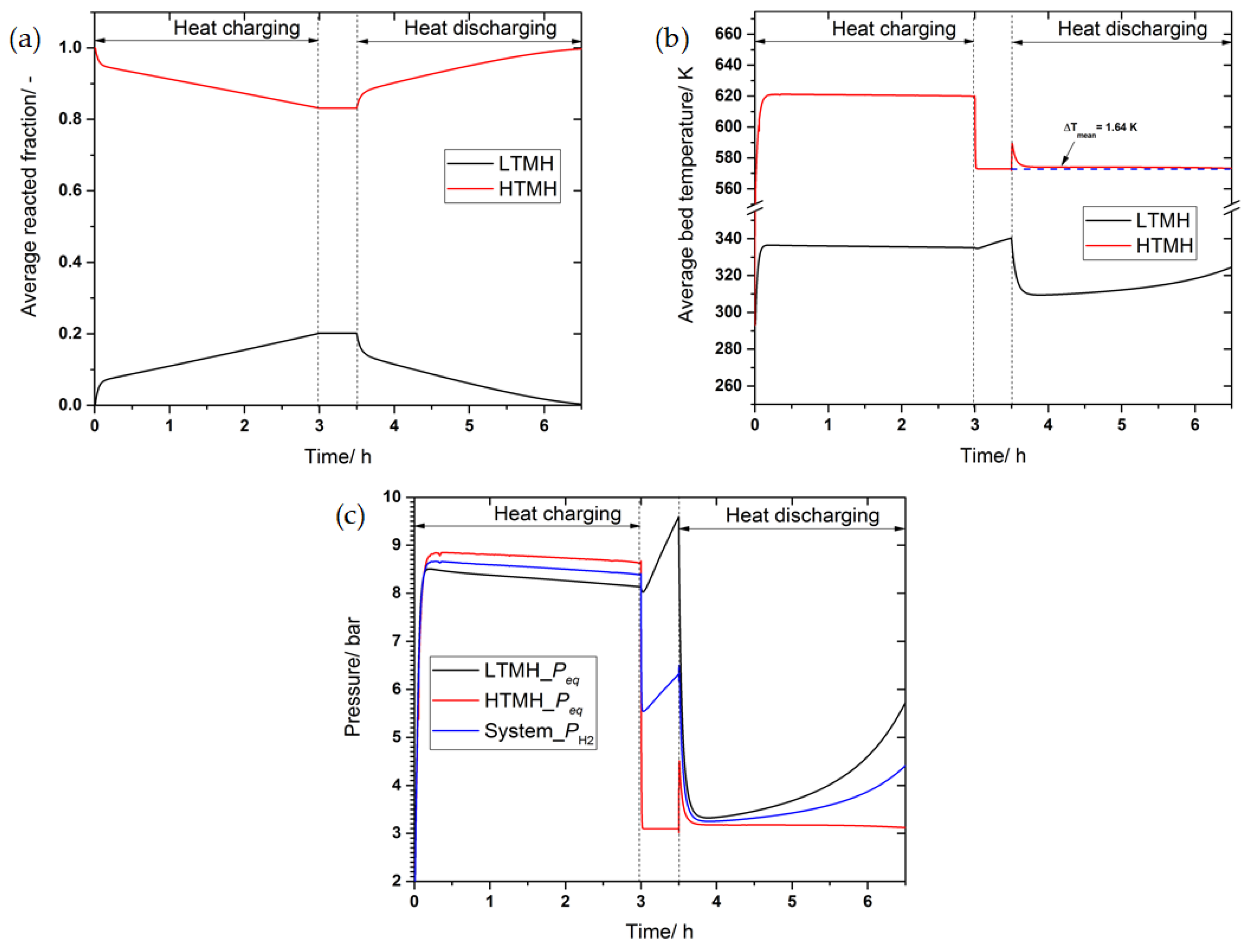
3.5. The Effect of Phase Change Material on the System’s Performance

Here, we analyze the performance of Config. 5. This design can attract further research interest since it has not been well considered yet in the literature. The selection of the phase change material should be critical since it should match the thermal behavior of the LTMH bed. For the simulations, we have chosen two different commercially available organic-based phase change materials [47]. Their properties are listed in Table 3. It can be seen in the table that the only difference between these materials is the transition (melting) temperature. Moreover, for the last parameter used, the PCM jacket volume is equal to 3.5 times the volume of R2. As a result, the theoretical energy storage density decreases to 404.2 MJ·m−3.
Figure 11a shows the average reacted fraction, the temperature profile, and the heat storage system’s performance indicators. It is seen that when using RT31 during the heat charging process, LaNi5 absorbs 50.7% of its maximum H2 capacity, while in the heat discharging process, only 11.2% of the hydrogen is restored. It can be seen that when using a phase change material with a high melting temperature, RT42 can significantly improve the behavior. In this case, the LaNi5 bed absorbs 43.74% during the heat charging process, while restoring 34.71% during the heat discharging process, which is almost 79.34% of the hydrogen absorbed.
The imbalance in the beds’ temperature can explain the decrease in the hydrogen inventory during the heat storage cycle. As the H2 desorption process is temperature-dependent, the LTMH bed’s temperature (equilibrium pressure) is not high enough to drive a high amount of H2 to the HTMH bed. Moreover, it is seen in Figure 11b that during the heat discharging step, the LaNi5 bed using RT31 cools down quicker than that using RT42.
Based on the discussion mentioned above, the performance of the heat storage system used in Config. 5 is straightforward and is depicted in Figure 11c. As can be seen in this figure, the energy density and specific power outputs when using RT42 are ca. 142 MJ m−3 and 48 W (kg-Mg2Ni)−1, respectively. Note that the energy density is more than three times inferior to that of the other configurations due to the non-completion of the hydrogen absorption/desorption and the inclusion of the PCM-jacket volume in the calculation. Although the utilization of phase change material as a passive heat transfer technique is expected to improve the energy storage efficiency, it is strongly noticed that this is not the case. By using RT42, the energy efficiency of 48.98% has been reached, which falls short compared to that of Config. 2 and Config. 3 (Figure 9), for which the peak efficiencies are 66.38% and 78.5%, respectively.
To gain more insight into the heat and mass transfer phenomena in Config. 5, the beds’ temperature, H2 reacted fraction, and PCM melting fraction distributions are plotted in Figure 12 at different times. Initially, all the beds are at a constant temperature of 293K. As time proceeds (t = 1, 60, 120 min), there is a sudden increase in the bed temperature in R1 to 623 K, the applied heat charging temperature, and in R2 to 343 K, due to abrupt hydrogen absorption. Meanwhile, the PCM temperature increases rather slowly due to its low thermal conductivity.
However, the contours in Figure 13 show a clear demarcation of the reaction front. While the reaction front is parallel to the reactor wall in R1, it is not uniform in R2 (R2 is sandwiched between a cold PCM jacket and a hot connecting pipe filled with hot hydrogen gas coming from R1) at times superior to 1 min. In addition, at the beginning of the heat discharging process (t = 210 min), it is remarked that almost all of the phase change material has melted, while LaNi5 is partially hydrogenated. This implies that either the PCM volume was not judiciously sized to absorb all of the available heat in R2, or the PCM properties were not well suited to this application. In such a situation, an optimization process is required and will be presented in a future publication.

4. Conclusions

A thermal energy storage system’s performance based upon a two-tank metal hydride has been investigated in this study. The effect of heat transfer measures on performance criteria, such as energy storage density, storage efficiency, and specific power density has been analyzed and discussed in detail. These heat transfer measures encompass active (forced convection) and passive measures (natural convection, a PCM jacket, and thermal conductivity augmentation). The results showed that a TES working with forced convection provides better performance in terms of power output at the expense of energy storage efficiency, since part of the available energy is used to improve the system’s heat transfer. However, thermal conductivity augmentation (Config. 4) is recommended, as it leads to better performance among the passive techniques. The use of PCM can be potentially promising if the PCM is appropriately chosen. Primarily, it is shown that the transition temperature of the phase change should be above 40 °C in order for the low-temperature metal hydride to restore the hydrogen absorbed in the first half cycle of the process. Alternatively, for future study, the selection of a low-temperature metal hydride with a cold start capability, such as an AB2 type hydride, should be a promising option.

Author Contributions

Conceptualization, S.N.N. and I.T.; methodology, S.N.N.; software, S.N.N. and I.T.; validation, S.N.N.; formal analysis, S.N.N.; writing—original draft preparation, S.N.N. and I.T.; writing—review and editing, S.N.N. and I.T.; funding acquisition, I.T. All authors have read and agreed to the published version of the manuscript.

Funding

This work is supported by the European Union’s Horizon 2020 research and innovation programme under the Marie Skłodowska-Curie grant agreement No. 778307 (Call: H2020-MSCA-RISE-2017–Marie Skłodowska-Curie Research and Innovation Staff Exchange).

Institutional Review Board Statement

Not applicable.

Informed Consent Statement

Not applicable.

Data Availability Statement

Not applicable.

Conflicts of Interest

The authors declare no conflict of interest.

Nomenclature

CpHeat capacity (J·kg−1·K−1) V Velocity (m·s−1)
Cfhydraulic friction factorVVolume (m3)
CPConnecting pipewtH2 weight capacity (%)
DDiameter (m)Greek letters
dhHydraulic diameter (m)αConversion fraction, thermal diffusivity in Equation (23) (m2·s−1)
Ea,dActivation energy (J·mol−1)βThermal expansion in Equation (23) (K−1)
fmGraphite volume fractionεBed porosity
h0,1Convective heat transfer coefficient (W·m−2·K−1)ηPower efficiency of pump and motor, energy storage efficiency
HTFHeat transfer fluidλThermal conductivity (W·m−1·K−1)
HTMHHigh-temperature metal hydrideµDynamic viscosity (Pa·s) Equation
ΔHReaction heat (J·mol−1 H2)
Latent heat (kJ/kg)
νKinematic viscosity (m2·s−1)
ka,dReaction rate constant (s−1)ρDensity (kg·m−3)
KeffPermeability (m2)Superscript
LReactor length (m)¯¯Spatial average
LTMHLow-temperature metal hydrideSubscript
MgH2 molecular weight (kg·mol−1)aActivation, absorption
m ˙ Mass flow rate (kg·s−1)cCooling, charging
n Outward normal unit vector to the heat transfer interfacesdDesorption, discharging
NuDNusselt numbereffeffective
pPressure (Pa)eqequilibrium
PCMPhase change materialffluid
PrPrandtl numberggas
ΔPHydraulic pressure drop (Pa)hheating
QHeat exchanged (J)iinlet
rRadius (m)lliquid
RaDRayleigh numbermmelting
RgUniversal gas constant J·mol−1·K−1MHMetal hydride
ReDReynolds numberooutlet
ΔSEntropy change of the reaction (J·mol−1·K−1)sstorage system, solid
TTemperature (K)trtransition
tTime (s)wwater
ΔTHTF temperature difference (K)

References

  1. Feng, P.; Liu, Y.; Ayuba, I.; Wu, Z.; Yang, F.; Zhang, Z. Optimal design methodology of metal hydride reactors for thermochemical heat storage. Energy Convers. Manag. 2018, 174, 239–247. [Google Scholar] [CrossRef]
  2. Nyallang, S.N.; Lototskyy, M.; Tolj, I. Selection of metal hydrides-based thermal energy storage: Energy storage efficiency and density targets. Int. J. Hydrogen Energy 2018, 43, 22568–22583. [Google Scholar]
  3. Reiser, A.; Bogdanovic, B.; Schlichte, K. The application of Mg-based metal hydrides as heat energy storage systems. Int. J. Hydrogen Energy 2000, 25, 425–430. [Google Scholar] [CrossRef]
  4. Bogdanovic, B.; Ritter, A.; Spliethoff, B. A process steam generator based on the high-temperature magnesium hydride/magnesium heat storage system. Int. J. Hydrogen Energy 1995, 20, 811–822. [Google Scholar] [CrossRef]
  5. Zhao, B.; Cheng, M.; Liu, C.; Dai, Z. Cyclic thermal characterization of a molten-salt packed-bed thermal energy storage for concentrating solar power. Appl. Energy 2017, 195, 761–773. [Google Scholar] [CrossRef]
  6. Li, X.; Xu, E.; Song, S.; Wang, X.; Yuan, G. Dynamic simulation of two-tank indirect thermal energy storage system with molten salt. Renew. Energy 2017, 113, 1311–1319. [Google Scholar] [CrossRef]
  7. Abdulla, A.; Reddy, K.S. Effect of operating parameters on thermal performance of molten salt packed-bed thermocline thermal energy storage system for concentrating solar power plants. Int. J. Therm. Sci. 2017, 121, 30–44. [Google Scholar] [CrossRef]
  8. Yin, H.; Ding, J.; Jiang, R.; Yang, X. Thermocline characteristics of molten-salt thermal energy storage in porous packed-bed tank. Appl. Therm. Eng. 2017, 110, 855–863. [Google Scholar] [CrossRef]
  9. Mahfuz, M.H.; Kamyar, A.; Afshar, O.; Sarraf, M.; Anisur, M.R.; Kibria, M.A.; Saidur, R.; Metselaar, I.H.S.C. Exergetic analysis of a solar thermal power system with PCM storage. Energy Convers. Manag. 2014, 78, 486–492. [Google Scholar] [CrossRef]
  10. Ma, F.; Zhang, P. Investigation on the performance of a high-temperature packed bed latent heat thermal energy storage system using Al-Si alloy. Energy Convers. Manag. 2017, 150, 500–514. [Google Scholar] [CrossRef]
  11. Thaker, S.; Oni, A.O.; Kumar, A. Techno-economic evaluation of solar-based thermal energy storage systems. Energy Convers. Manag. 2017, 153, 423–434. [Google Scholar] [CrossRef]
  12. Corgnale, C.; Hardy, B.; Motyka, T.; Zidan, R.; Teprovich, J.; Peters, B. Screening analysis of metal hydride based thermal energy storage systems for concentrating solar power plants. Renew. Sustain. Energy Rev. 2014, 38, 821–833. [Google Scholar] [CrossRef]
  13. Sekhar, B.S.; Muthukumar, P.; Saikia, R. Tests on a metal hydride based thermal energy storage system. Int. J. Hydrogen Energy 2012, 37, 3818–3824. [Google Scholar] [CrossRef]
  14. Sheppard, D.A.; Paskevicius, M.; Buckley, C.E. Thermodynamics of hydrogen desorption from NaMgH3 and its application as a solar heat storage medium. Chem. Mater. 2011, 23, 4298–4300. [Google Scholar] [CrossRef]
  15. Fang, Z.Z.; Zhou, C.; Fan, P.; Udell, K.S.; Bowman, R.C.; Vajo, J.J.; Kekelia, B. Metal hydrides based high energy density thermal battery. J. Alloys Compds. 2015, 645, 184–189. [Google Scholar] [CrossRef] [Green Version]
  16. Paskevicius, M.; Sheppard, D.A.; Williamson, K.; Buckley, C.E. Metal hydride thermal heat storage prototype for concentrating solar thermal power. Energy 2015, 88, 469–477. [Google Scholar] [CrossRef]
  17. Poupin, L.; Humphries, T.D.; Mark Paskevicius, M.; Buckley, C.E. An experimental high temperature thermal battery coupled to a low temperature metal hydride for solar thermal energy storage. Sustain. Energy Fuels. 2020, 4, 285–292. [Google Scholar] [CrossRef]
  18. Bogdanovic, B.; Ritter, A.; Spliethoff, B. Active MgH2-Mg Systems for Reversible Chemical Storage. Angew. Chem. Int. Ed. Engl. 1990, 29, 223–234. [Google Scholar] [CrossRef]
  19. Ward, P.A.; Corgnale, C.; Teprovich, J.A.; Motyka, T.; Hardy, B.; Peters, B.; Zidan, R. High performance metal hydride based thermal energy storage systems for concentrating solar power applications. J. Alloys Compds. 2015, 645, S374–S378. [Google Scholar] [CrossRef] [Green Version]
  20. Bao, Z.; Yuan, S. Performance investigation of thermal energy storage systems using metal hydrides adopting multi-step operation concept. Int. J. Hydrogen Energy 2016, 41, 5361–5370. [Google Scholar] [CrossRef]
  21. Bao, Z. Performance investigation and optimization of metal hydride reactors for high temperature thermochemical heat storage. Int. J. Hydrogen Energy 2015, 40, 5664–5676. [Google Scholar] [CrossRef]
  22. d’Entremont, A.; Corgnale, C.; Hardy, B.; Zidan, R. Simulation of high temperature thermal energy storage system based on coupled metal hydrides for solar driven steam power plants. Int. J. Hydrogen Energy 2018, 43, 817–830. [Google Scholar] [CrossRef]
  23. Malleswararao, K.; Aswin, N.; Srinivasa, S.; Murthy, S.S.; Dutta, P. Performance prediction of a coupled metal hydride based thermal energy storage system. Int. J. Hydrogen Energy 2020, 45, 16239–16253. [Google Scholar] [CrossRef]
  24. Mellouli, S.; Askri, F.; Edacherian, A.; Alqahtani, T.; Algarnia, S.; Abdelmajid, J.; Phelan, P. Performance analysis of a thermal energy storage system based on paired metal hydrides for concentrating solar power plants. Appl. Therm. Eng. 2018, 144, 1017–1029. [Google Scholar] [CrossRef]
  25. Bao, Z.; Yang, F.; Wu, Z.; Nyallang, N.S.; Zhang, Z. Optimal design of metal hydride reactors based on CFD—Taguchi combined method. Energy Convers. Manag. 2013, 65, 322–330. [Google Scholar] [CrossRef]
  26. Afzal, M.; Mane, R.; Sharma, P. Heat transfer techniques in metal hydride hydrogen storage: A review. Int. J. Hydrogen Energy 2017, 42, 30661–30682. [Google Scholar] [CrossRef]
  27. Yang, F.S.; Wang, G.X.; Zhang, Z.X.; Rudolph, V. Investigation on the influences of heat transfer enhancement measures in a thermally driven metal hydride heat pump. Int. J. Hydrogen Energy 2010, 35, 9725–9735. [Google Scholar] [CrossRef]
  28. Ron, M.; Gruen, D.; Mendelsohn, M.; Sheft, I. Preparation and properties of porous metal hydride compacts. J. Less Common Metals 1980, 74, 445–448. [Google Scholar] [CrossRef]
  29. Isselhorst, A.; Groll, M. Two-stage metal hydride heat transformer laboratory model. J. Alloys Compds 1995, 231, 888–894. [Google Scholar] [CrossRef]
  30. Werner, R.; Groll, M. Two-stage metal hydride heat transformer laboratory model: Results of reaction bed tests. J. Less Common Metals 1991, 172–174, 1122–1129. [Google Scholar] [CrossRef]
  31. Klein, H.P.; Groll, M. Development of a two-stage metal hydride system as topping cycle in cascading sorption systems for cold generation. Appl. Therm. Eng. 2002, 22, 631–639. [Google Scholar] [CrossRef]
  32. Chaise, A.; de Rango, P.; Marty, P.; Fruchart, D.; Miraglia, S.; Olives, R.; Garrier, S. Enhancement of hydrogen sorption in magnesium hydride using expanded natural graphite. Int. J. Hydrogen Energy 2009, 34, 8589–8596. [Google Scholar] [CrossRef]
  33. Pohlmann, C.; Röntzsch, L.; Kalinichenka, S.; Hutsch, T.; Kieback, B. Magnesium alloy-graphite composites with tailored heat conduction properties for hydrogen storage applications. Int. J. Hydrogen Energy 2010, 35, 12829–12836. [Google Scholar] [CrossRef]
  34. Muthukumar, P.; Groll, M. Metal hydride based heating and cooling systems: A review. Int. J. Hydrogen Energy 2010, 35, 3817–3831. [Google Scholar] [CrossRef]
  35. Mellouli, S.; Abhilash, E.; Askri, F.; Nasrallah, S.B. Integration of thermal energy storage unit in a metal hydride hydrogen storage tank. Appl. Therm. Eng. 2016, 102, 1185–1196. [Google Scholar] [CrossRef]
  36. Mâad, H.B.; Miled, A.; Askri, F.; Nasrallah, S.B. Numerical simulation of absorption-desorption cyclic processes for metal-hydrogen reactor with heat recovery using phase-change material. Appl. Therm. Eng. 2016, 96, 267–276. [Google Scholar] [CrossRef]
  37. Darzi, A.A.R.; Afrouzi, H.H.; Moshfegh, A.; Farhadi, M. Absorption and desorption of hydrogen in long metal hydride tank equipped with phase change material jacket. Int. J. Hydrogen Energy 2016, 41, 9595–9610. [Google Scholar] [CrossRef]
  38. Nyamsi, S.N.; Yang, F.; Zhang, Z. An optimization study on the finned tube heat exchanger used in hydride hydrogen storage system- analytical method and numerical simulation. Int. J. Hydrogen Energy 2012, 37, 16078–16092. [Google Scholar] [CrossRef]
  39. Nyallang, N.S.; Tolj, I.; Lototskyy, M. Metal hydride beds-phase change materials: Dual-mode thermal energy storage for medium-high temperature industrial waste heat recovery. Energies 2019, 12, 3949. [Google Scholar] [CrossRef] [Green Version]
  40. Nyallang, N.S.; Lototskyy, M.; Tolj, I. Optimal design of combined two-tank latent and metal hydrides-based thermochemical heat storage systems for high-temperature waste heat recovery. Energies 2020, 13, 4216. [Google Scholar]
  41. Abdin, Z.; Webb, C.J.; Gray, E.M. One-dimensional metal-hydride tank model and simulation in Matlab -Simulink. Int. J. Hydrogen Energy 2018, 43, 5048–5067. [Google Scholar] [CrossRef]
  42. Laurencelle, F.; Goyette, J. Simulation of heat transfer in metal hydride reactor with aluminum foam. Int. J. Hydrogen Energy 2007, 32, 2957–2964. [Google Scholar] [CrossRef]
  43. Chung, C.A.; Lin, C.S. Prediction of hydrogen desorption performance of Mg2Ni hydride reactors. Int. J. Hydrogen Energy 2009, 34, 9409–9423. [Google Scholar] [CrossRef]
  44. Incropera, F.; DeWitt, D.; Bergman, T.; Lavine, A. Fundamentals of Heat and Mass Transfer, 6th ed.; John Wiley & Sons: Hoboken, NJ, USA, 2007; p. 580. [Google Scholar]
  45. Perry, R.; Green, D.W.; Maloney, J.O. Perry’s Chemical Engineers’ Handbook, 7th ed.; McGraw Hill: New York, NY, USA, 1997; Chapter 6: Tables 4–6. [Google Scholar]
  46. Siyabi, I.A.; Khanna, S.; Mallick, T.; Sundaram, S. An experimental and numerical study on the effect of inclination angle of phase change materials thermal energy storage system. J. Energy Storage 2019, 23, 57–68. [Google Scholar] [CrossRef]
  47. Lizana, J.; Chacartegui, R.; Barrios-Padura, A.; Valverde, J.M. Advances in thermal energy storage materials and their applications towards zero energy buildings: A critical review. Appl. Energy 2017, 203, 219–239. [Google Scholar] [CrossRef]
Figure 1. Schematic of a metal hydride pair based heat storage system for CSP plant applications.
Energies 14 03006 g001
Figure 2. Computational volume of different heat transfer configurations of the low-temperature metal hydride reactor: (a) active cooling/heating using water as an HTF; (b) active cooling/heating using air as an HTF; and (c) passive cooling/heating using a phase change material jacket.
Energies 14 03006 g002
Figure 3. Simulation flowchart using an FEM package COMSOL MULTIPHYSICS.
Energies 14 03006 g003
Figure 4. Grid independence verification: (a) the average HTMH bed temperature and (b) the average reacted fraction.
Energies 14 03006 g004
Figure 5. The convective heat transfer coefficient and the HTF displacement work as a function of the HTF’s flow rate. (a) Synthetic oil and water as the HTF. (b) Air as the HTF.
Energies 14 03006 g005
Figure 6. Dynamic characteristics of Config. 1: (a) Temporal profile of the H2 reacted fraction, (b) temporal profile of the average bed temperature, (c) temporal profile of the hydrogen and equilibrium pressures of the hydride materials.
Energies 14 03006 g006
Figure 7. Dynamic characteristics of Figure 2: (a) Temporal profile of the H2 reacted fraction, (b) temporal profile of the average bed temperature, (c) temporal profile of the hydrogen and equilibrium pressures of the hydride materials.
Energies 14 03006 g007
Figure 8. Dynamic characteristics of Config. 3: (a) Temporal profile of the H2 reacted fraction, (b) temporal profile of the average bed temperature, and (c) temporal profile of the hydrogen and equilibrium pressures of the hydride materials.
Energies 14 03006 g008
Figure 9. The performance indicators are energy density, specific power output, and energy storage efficiency.
Energies 14 03006 g009
Figure 10. The influence of thermal conductivity increases the performance of the heat storage system (Config. 4): (a) Temporal profile of the H2 reacted fraction, (b) temporal profile of the average bed temperature, and (c) the performance indicators are energy density, specific power output, and energy storage efficiency.
Energies 14 03006 g010
Figure 11. The influence of phase change materials on the performance of the heat storage system: (a) Temporal profile of the H2 reacted fraction, (b) temporal profile of the average bed temperature, and (c) the performance indicators are energy density, specific power output, and energy storage efficiency.
Energies 14 03006 g011
Figure 12. Temperature spatial distribution in computational volume at different time intervals during the heat charging/discharging process.
Energies 14 03006 g012
Figure 13. H2 reacted fraction/PCM liquid fraction spatial distribution in computational volume at different time intervals during the heat charging/discharging process.
Energies 14 03006 g013
Table 1. The starting parameters utilized in the numerical model.
Mg2Ni [43]LaNi5 [2]
Enthalpy of formation/kJ·mol−164.530.5
Entropy of formation/J·mol−1 K−1122.2108
Activation energy, abs-des/kJ·mol−152.20/63.4621.17/16.47
Rate constant abs-des/s−1175/5452.259.18/9.57
Density/kg·m−332008400
Specific heat, M-MH/J·kg−1·K−1697419
Max hydrogen capacity/wt%3.61.39
Porosity0.50.5
Permeability/m2 1.3 × 10−121.3 × 10⁻¹²
Effective thermal conductivity/W·m−1·K−111
Hydride thickness/m0.0270.025
H2 filter radius, r0/m0.0030.003
Hydraulic diameter dh/m0.0030.003
Reactor length LMH/m0.450.45
Table 2. Thermo-physical properties of the HTFs and stainless steel 316L.
ParameterValue/Range
SS316LGraphiteWater (298 K)Therminol VP-1 [6] (623 K)Dry Air (293 K)
Density ρ/kg·m−37990220010007611.2
Specific heat, Cp/J·kg−1·K−1500710418024541000
Thermal conductivity/W·m−1·K−116.217.90.590.0860.025
Dynamic viscosity/mPa.s--0.89 0.177 18.1 × 10⁻³
Cooling fluid temperature Tc/K--293573293
Heating fluid temperature Th/K--353623353
Table 3. Thermo-physical properties of Rubitherm-based phase change materials [47].
PCMMelting Temperature/°CDensity, Solid/Liquid/kg∙m−3Thermal Conductivity/W∙m−1∙K−1Specific Heat, Cp/J·kg−1·K−1Latent Heat of Fusion/kJ∙kg−1Volumetric Heat Capacity/MJ∙m−3
RT3131880/7600.22000165145
RT4242880/7600.22000165145
Publisher’s Note: MDPI stays neutral with regard to jurisdictional claims in published maps and institutional affiliations.

