Abstract
This paper presents a novel maximum power point tracking method for photovoltaic inverters with a single phase connection to the onboard 400Hz vehicle or aircraft grid, supplying drives operating in a critical mode. By taking into account that the power fluctuations cause voltage ripples at the termini of photovoltaic panels connected to the DC-link capacitor, this paper proposes a conductance base maximum power point tracking method. The impact of varying voltage has been reduced to ensure the constant reference current for the grid current calculation problem, which has been reported in previous studies. Accordingly, a conductance base tracking method, grid current control, is proposed and implemented to ensure the expected output current with respect to varying power. As described in this paper, the exemplified solar converter prototype can implement constant reference photovoltaic current control with a maximum power point achievement under continuous voltage rippling. Experimental results are given to verify the feasibility of the proposed MPPT method, which significantly improves the power efficiency for solar powered vehicles or aircraft.
1. Introduction
In the last couple of decades, many studies on the use of solar energy, especially for vehicles or aircraft, have been conducted because of its abundance, renewability and clean nature [1,2]. The solar energy conversion needs an effective piece of technology which allows it to convert solar irradiance directly to electrical energy through a photovoltaic panel (PvP) connected to a power converter [3]. If the load is connected with the solar energy source through the grid, the solar inverters must be used in order to change the solar DC current to the AC current. A higher amount of the solar energy usage is described for the solar plants in which the photovoltaic (PV) inverters feed the energy directly to the grid. The intense popularity of solar energy exists for solar home systems where the grid inverter supplies the household appliances, and energy overproduction is directed into the grid.
In connection to solar-based power systems, solar powered aircraft systems are being investigated due to the feasibility of the energy management of the high altitude platform reported in [4], and select solutions were technically tested for an aircraft which is able to cruise directly on 5 kW solar power with two people onboard [5]. In [6] the basic concept of a high-altitude aerostatic platform to support PV modules to substantially increase their output by virtue of the significantly enhanced solar radiation at the operating altitude of the aerostat was investigated and demonstrated using standard equations and realistic values for the relevant engineering parameters. The specific tasks, such a greenhouse gas monitoring in difficult-to-access areas can be realized by the integration of a solar-powered unmanned aerial vehicle and a wireless sensor network. Laboratory, bench and field-testing results are demonstrated in [7]. The solar-powered system operating in an airplane must be characterized by strongly restricted features. The main feature is cooperation with the onboard grid, which is usually a digitally controlled high-power 400 Hz supply system [8]. Taking into account grid parameters, the solar converter must meet the same requirements as a classical grid converter operating at 400 Hz grid.
The solar powered vehicle is becoming an increasingly interesting alternative to urban transport. The vehicle must operate in a critical mode and must be characterized by high energy efficiency. With electric vehicles comes the battery charging problem; it is widely studied. Among the scientific problems being studied are the solar-based chargers, which can deliver solar power to the grid or charge a battery. An intelligent, solar-powered, battery-buffered EV charging station with solar electricity forecasting and EV charging load projection functions are depicted in [9].
If the current source, which is PvP, is directly connected to a single-phase DC-AC inverter, the power fluctuation produced by the AC side is observed. As a consequence of it, low-frequency voltage ripples at the capacitor connected with the PvP terminals are observed. In case of the conventional three-phase inverter or multi-level inverter the ripple frequency is higher and much smaller in amplitude. As a consequence of the voltage ripple, the output power ripple from the PvP appears due to PV voltage changes near the power at the maximum power point (MPP). This power ripple reduces the solar system’s efficiency and reliability [10]. If the power ripple is not well suppressed or controlled, it could be propagated to the PV side and affect the accuracy of maximum power point tracking (MPPT) [11]. Inaccurate power tracker operation can be improved by the installation of large electrolytic capacitors on the DC-link side which absorb the power ripple. The capacitance of such capacitors is large, and its lifetime is usually limited and may reduce the system reliability [12]. In order to mitigate or eliminate the power ripple, several power decoupling topologies and control methods have been presented in literature. In general, power decoupling techniques used in one-phase systems are classified into two main camps. The first of them refers to the additional active circuit implementation; the second group refers only to the control method modification by the implementation of the voltage or current waveform reshaping techniques [11,13]. When the active circuits are used, the oscillating power is propagated through the additional reactive elements due to the capacitive or inductive energy storage capability. The power decoupling techniques based on the additional circuit implementation may be implemented as series or parallel circuits’ installation on the AC, DC-link or AC side, as described in [13]. The size and volume of the additional resonant induction-capacitive components used in an auxiliary circuit would be very large owning to the relatively low resonant frequency, which significantly reduces the application area especially in an aircraft’s system. When the bulky electrolytic capacitor or additional active or resonant circuit implementation is limited, the second harmonic current in a two-stage single-phase converter’s effect can be limited by the proper control method implementation. The review in [14] presents the DC-DC converters in the two-stage single-phase rectifier or inverter operated as a bus-voltage-controlled converter or a bus-current-controlled converter, in which the operation mode has a profound impact on selecting the proper second harmonic reduction approach. The second-harmonic current value in the DC-DC converter is connected with its output impedance value and the impedance of the DC-link at double frequency. Therefore, the current ripple can be limited by its increased output impedance and proper control method [15,16,17]. In [18] authors describe the hybrid one-cycle control strategy for electrolytic capacitor-less second harmonic compensator with excellent compensation performance achieved by a proper charging and discharging mode detection. The ripple reduction effect of DC-link voltage was depicted in [19], wherein a transformer-less modular generator system operates with proposed controller. The second harmonic current reduction methods are investigated even in kilowatt-scale converters. In [20] the benchmark study of active power decoupling (APD) for hi-power single-phase inverters was presented, where the feasibility and superiority of the identified solution for APD with the adaptive decoupling voltage control method were experimentally verified.
The solar-powered aircraft or vehicle systems generate the specific requirements for used power electronics devices (PED). The main scientific problems are the reduction of PED physical dimensions and increased power efficiency. The second harmonic current reduction control methods allow the use of the electrolyte-free inverters, which improves the grid current quality. As a result of it, the PV-side capacitance can also be greatly reduced, as is shown in [21]. In addition, improving the MPPT method with the second harmonic current limitation, the system performance is enhanced [22].
Taking into account an analysis of possible solutions of the voltage ripple reduction methods, the paper proposes a conductance-based method for the MPPT algorithm with power fluctuation effect reduction when the solar system is connected to an onboard 400Hz grid. Classical MPPT methods are easy to implement, and due to fixed perturbation steps, they are easy to use and relatively cheap. Unfortunately, using, fixed-step methods the power oscillates at MPP and the tracking speed is low. One of the classical, most commonly used MPPT methods is an incremental conductance (INC) method. This method gives simple and accurate control, which is characterized by a fast response speed when the light intensity is changing. The control algorithm principle is based on the PV voltage and current measurement and requires accurate sensors, which increases the hardware cost [23,24,25]. When the power fluctuation causes a voltage ripple, the constant-perturbation-step MPPT methods cease to be energy-efficient algorithms.
The main scientific problems of a single-phase solar-powered vehicle or aircraft system are the inaccurate power tracking system, the unreliability and the dimensions of the devices. These problems arise, among other causes, from the power pulsation of the single-phase inverter. In this paper, a conductance-based MPPT method is proposed which performs continuous grid current reference calculations for the grid converter, which operates as an element of a 400Hz onboard airplane platform or as an element of a solar-powered EV. The proposed method can effectively solve the problem of traditional INC method used for a single-phase high frequency system. Compared with the fixed step size INC method tuned for the specified solar irradiance, the proposed method is characterized by higher energy efficiency under power oscillation without a voltage step generation. The second harmonic current limitation with the proposed MPPT method allows for the bulky DC-link and PV-side capacitors reduction. Experimental results verify the effectiveness of the proposed algorithm.
2. Photovoltaic System Structure
The energy produced in the photovoltaic panels can be delivered to the one-phase 400Hz onboard grid (O-PG) after proper conversion of current and voltage parameters. Firstly, the DC PV voltage must be brought to the appropriate value, which will allow energy flow to the grid. Therefore, the DC voltage value depends on the grid voltage and specifies the state in which the PV system can be in active mode. Such a situation requires the DC–DC converter of boost type (BOOST) usage, whose role is to increase and stabilize the DC voltage value. In a few cases, when the PV voltage is sufficiently large, the DC–DC converter can be of buck-boost type. The second stage of the voltage conversion process is the DC–AC conversion, which takes place in the grid converter (GC). The voltage waveform in the point of coupling (PC) must be strongly synchronized with the fundamental harmonic of the grid voltage in order to the reactive power limitation. The grid converter operates with the high frequency switching and requires a low-pass filter (LPF) to be used between its output and grid. The considered power electronics structure (PE) is shown in Figure 1a.
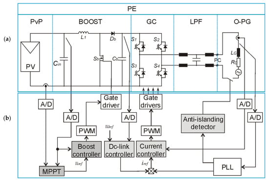
Figure 1.
One-phase photovoltaic system diagram: (a) power electronics part; (b) control structure.
The main task of the energy flow control in PE is to maximize the energy value extracted from the PV panels under variable solar irradiation and deliver it to the grid. To make this task effective, the considered control system must track the maximum PV power and synchronously control the grid current. Each PV system operating with the grid requires the following functions:
- Maximum power point tracking (realized in MPPT block)
- DC-link control (realized in the boost controller block as a proportional-integral (PI) control)
- Grid current control (realized in current controller block as a PI control with PLL)
- Anti-islanding protection system.
As the authors in [26] suggest, the PvP voltage control is the best solution which results in a current fluctuation when the voltage remains fixed. Therefore, the DC-link controller has a standard PI type control scheme and is run as an independent instance in order to stabilize the output DC voltage at the given value. If the determined DC voltage value cannot be achieved, then in the PV system shutdown process is activated. The anti-islanding protection system was elaborated based on the voltage frequency deviation methods, described in detail in [27,28,29]. This part of the protection system shuts down the system when the frequency is out of the nominal range. The grid current controller’s main task is to obtain the sine wave grid current without a phase shift with an amplitude depending on photovoltaic current. For this purpose, the DC-link voltage controller calculates the grid current reference signal and multiplies it with a shape signal of the fundamental harmonic of the grid voltage achieved from the phase locked loop (PLL). Next, the grid current controller of PI type structure with pulse width modulation (PWM) drives inverter switches. This is a typical control method in a grid converter, and it is, therefore, not discussed in detail in this paper. The main problem described in the paper refers to the new concept of the maximum power point tracking system, elaborated based on the incremental conductance method adopted for the voltage rippling observed in the DC side of the PE. The ripples are caused by the energy flow between the DC side and the one-phase AC side. The equation of instantaneous power balance in considered system can be expressed as (Equation (1)):
where pDC is the PvP power and pAC is the instantaneous power delivered to the grid. The PvP power is the DC side power of solar panels; and for unchanged external factors, temperature and solar irradiance are constant. Then it can be expressed as (Equation (2)):
where VPV, IPV are the photovoltaic voltage and current respectively; PPV is the PvP power. The instantaneous power of one-phase grid can be calculated based on:
where VG, IG are the root-mean-square (RMS) values of the fundamental grid voltage and current respectively; PG is the grid active power. According to Equation (3) the dual frequency power component must be balanced in the boost converter capacitors and causes a voltage ripple observed in Cin. The varying voltage at the PV terminals makes traditional MPPT trackers ineffective; therefore, the novel continuous conductance base MPPT method was implemented and tested. This method is elaborated based on the PvP power derivative calculated as:
where vPV and iPV are the actual voltage and current of PvP respectively. According to Equation (4) the fundamental equation of an incremental conductance method of the MPPT can be obtained as:
pDC(t) = pAC(t),
pDC(t) = VPV IPV = PPV,
By ignoring dual frequency ripples deduced in Equation (3), the MPP of the PvP can be obtained when Equation (5) is equal zero. Then the MPP of the PvP can be detected for a given condition:
In the one-phase photovoltaic system, the voltage and current of the PvP are varied in order to balance the dual frequency component. Then, the MPP of the PVP, using the incremental-conductance-based method, cannot be precisely detected, even at different time steps. The PvP voltage changes result in power changes around the MPPT point. To eliminate the effect of PvP voltage changes, the new concept was deduced and implemented in the power tracking system. The relation between the left and right sides of Equation (6) changes during normal operation, when the PvP exceeds the MPP according to the rules:
In a classical incremental-conductance-based method, Equations (7) and (8) are used in order to increase or decrease the photovoltaic voltage and obtain the MPP during steady-state operation. When the voltage ripple is observed, the power changes around the MPP. The proposed solution checks the Equations (7) and (8) in each time period, and the result is integrated over the constant cycle. The integration result is taken as the photovoltaic current reference value as:
where TC is the integration time constant.
The graphical interpretation of proposed MPPT method of the photovoltaic system for one-phase system is shown in Figure 2. The situation in which the external PvP condition changes was taken into consideration. As an effect of solar irradiance and temperature change, the PvP power-to-voltage characteristic changes, resulting in the maximum power point movement from MPP1 to MPP2.
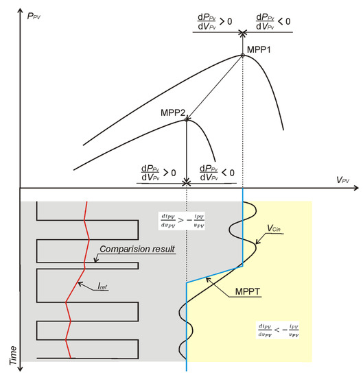
Figure 2.
Graphical interpretation of the reference current generation by the MPPT for a one-phase system under voltage ripples and external condition changes.
The voltage ripples observed on PvP terminals cause that the static operating conditions to not be established. For steady state operations, the power derivative changes character after a voltage ripple periodically. The area in which the power-voltage characteristic is falling is highlighted in yellow; for the rising part the color is grey. The blue line shows the MPP during the considered change in a PvP external conditions. The power derivative character after the PvP voltage is obtained by the comparison of photovoltaic current increment to photovoltaic voltage increment ratio and negative current to voltage ratio, as in Equation (9). The integrated comparison result proceeded for constant integration time is the reference grid current value for PI current control. The detailed MPPT scheme is presented in Figure 3. The sampled (in zero-order hold blocks (ZOH)) photovoltaic current (IPV) to voltage (VPV) ratio with negative gain k = −1 (K) is compared with its increment ratio calculated based on the unit delay block and then integrated with the time constant.
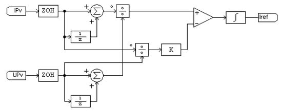
Figure 3.
MPPT scheme based on the photovoltaic current (IPV) and voltage (VPV) measurements.
The grid converter for a one-phase system with the proposed MPPT method, shown in Figure 1, was tested using simulation environment—PSIM (Power Electronics Simulator)—software based on the embedded physical model of PV cells with user-defined characteristics in order to confirm the assumed power tracking concept. This model is well known and widely described in the literature; for example, in [25]. After positive confirmation of the proposed tracker’s operation, the physical model of photovoltaic system was elaborated and build. The digital model of control system was made using field programmable logic device (FPGA) Altera EP4CE22E22C6N with the independent function instances operating in parallel. The grid converter driver was defined using very high speed integrated circuit hardware description language (VHDL) implemented in the Quartus II software environment. To measure and acquire data during driver operation, the embedded tools were used, such as the Signal Tap II Logic Analyzer. The power electronics part of grid converter and DC–DC boost converter shown in Figure 1 was designed and made for parameters given in Table 1. For the power switches in the DC–DC boost converter and DC–AC inverter, the high speed IGBT transistors of IKW15N120H3 type were used. These transistors were driven by the UCC21520 isolated dual-channel gate drivers with 4A sources, and 6A sink peak current was used, which is able to drive power IGBT’s up to 5 MHz with best-in-class propagation delay and pulse-width distortion. For the electronic measurement of currents and voltages with a galvanic isolation between high power circuit and the electronic circuit the LEM, sensors using the Hall effect were used. The measured signals were digitalized in a MAX1304 8-channel, 12-bit analog-to-digital converter with short conversion time (1.98 us) and high throughput (456 ksps). For the PvP emulator, the ITECH IT6526C DC power supply was used, which is characterized by the solar panel characteristic simulator. In this device the Sandia model for PV modules was used, which is fully described in the report SAND2004-3535 (2004) directly available on the web. Using software SAS1000L corresponding to this device, the related voltage power curve parameters can be configured; irradiance and temperature curves based on selected weather parameters can be selected or created, and measurement of the MPP under these circumstances can be done. Based on this PV emulator, both the static and dynamic tests can be performed. The physical signals, currents and voltages were measured using Yokogawa DLM2000 mixed signal oscilloscope as a part of hardware setup shown in Figure 4.

Table 1.
Parameters of boost converter and grid converter.
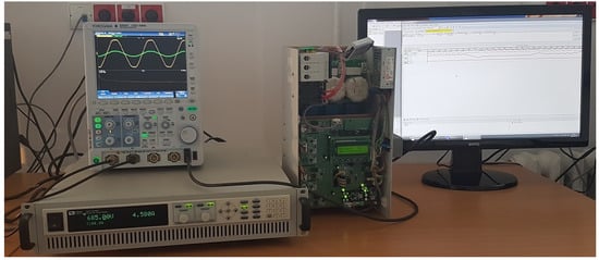
Figure 4.
Hardware setup with power converter, photovoltaic panel (PvP) system emulator and Yokogawa mixed signal oscilloscope.
The MPPT tune process was performed based on the heuristic response time optimization method. Solar irradiance falling and rising steps between 1000 and 800 W/m2 were generated and response time values were measured, which were determined by 10% of the steady state output signal. For the selection of the optimal integration constant time value, the shortest response times for falling and rising solar irradiance steps were assumed. Based on experiments performed for falling and rising solar irradiances, the integration constant time (Tc) was assumed as 0.00125. The results of tuning process are presented in Figure 5.
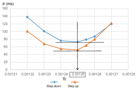
Figure 5.
Response time tr in ms of the proposed MPPT method, measured for falling irradiance from 1000 to 800 W/m2—step down and rising irradiance from 800 to 1000 W/m2; step up for given integration constant time Tc.
3. Results
This section describes investigation results of the one-phase photovoltaic converter designed to demonstrate proposed MPPT method. In order to show advantages of new power tracker, the standard incremental conductance method was implemented and run as an independent instance in the same control device. The results of proposed MPPT method were compared with the most closely similar method to the proposed one—the incremental conductance method with a fixed step size, marked INC2 and called the standard method in the paper. This method is well known and widely described in the literature. The detailed characteristics of the incremental conductance method are presented in [25]. The power and response time were measured and compared for the considered MPPT methods under a variable environment and control parameters. The selected internal control device signals are acquired in order to show the principle of proposed MPPT method operation, described in Section 2. Firstly, the comparative results of the photovoltaic current to voltage ratios with their increments were registered and the generated current reference signal was presented for pooling process visualization under variable solar irradiance. The obtained signals from Signal Tap II Logic Analyzer are presented in Figure 6. As it can be observed in Figure 6, the solar irradiance step changes the on–off ratio δ as an effect of PvP characteristic shift and moves the MPP by the reference current modification.

Figure 6.
Internal control signals of FPGAs for the proposed MPPT method registered under solar irradiance s steps at temperature 297 in K: δ is the comparison result, Iref is a digital current reference.
In order to verify the ripple effect limitation, the characteristic waveforms of voltages and currents of a prototype were measured. Figure 7 shows the measured 400Hz single-phase grid voltage and current and the DC-link voltage, and the PvP output current, for the standard-incremental conductance method (Figure 7a) and proposed conductance method (Figure 7b). The waveforms presented in Figure 7a show the best case of standard INC2 method operation, when the environmental conditions were equal to the conditions for which this method was tuned. For the same conditions, the proposed MPPT method was used and the results are depicted in Figure 7b. As it can be observed, both the DC-link voltage and the PvP current have the fixed offset. The measured fixed-offset of DC-link voltage (equal 700 V) relays to the constant reference DC-voltage. This voltage is the same for both tested methods because it is controlled by the AC-side controller. The measured fixed-offset of PvP current, equal ti 3.65 A for the INC 2 method and 3.5 A for the proposed one, is connected with the implemented MPPT operation. As can be observed, the grid current for the standard MPPT varying with low frequency and its fixed, slightly larger offset indicate that the MPP has not been achieved, because measured AC-side power was 40 W higher for the proposed MPPT method implementation. This situation was observed due to the fixed step period used in the INC2 method and was eliminated by the continuous current reference in the proposed MPPT algorithm. When the solar irradiance changes in relation to the INC2 tuning point, then the proposed system performance is significantly higher, as can be observed in Figure 8 and Figure 9. This shows that the performance of the proposed system is immune to the double-frequency voltage ripple. The sinusoidal grid-current voltage ripple in the DC-link (approximately 34 V) and the PvP current waveforms highlight the PV-side double-line ripple rejection.
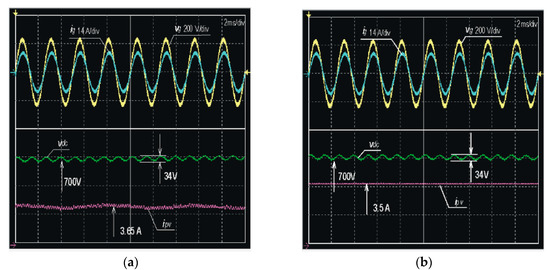
Figure 7.
Experimental results showing the grid voltage vg in V and current ig in A, decoupling capacitor voltage vdc in V with the fixed DC offset, and the PvP output current iPV in A with the fixed DC offset for: (a) the incremental conductance method with a fixed step; (b) the proposed MPPT method.
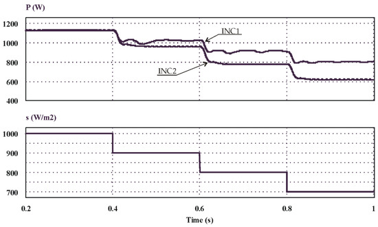
Figure 8.
Measured power P in W delivered to the grid and solar irradiance s in W/m2 for the proposed MPPT method (INC1) and for the incremental conductance MPPT method (INC2) with the increment value tuned for solar irradiance of 1000 W/m2.
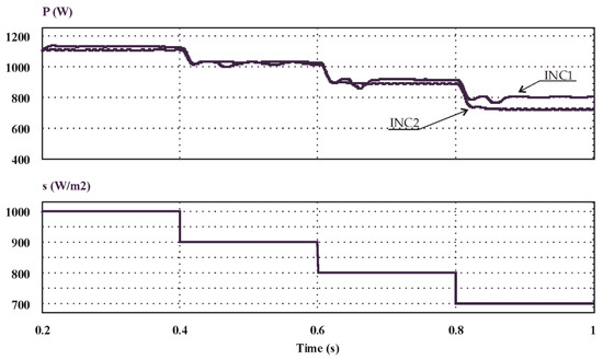
Figure 9.
Measured power P in W delivered to the grid and solar irradiance s in W/m2 for the proposed MPPT method (INC1) and for the incremental conductance MPPT method (INC2) with the incremental value tuned for solar irradiance of 900 W/m2.
In order to verify the feasibility of the proposed incremental-conductance-based MPPT method for one-phase systems, the designed grid converter was checked under fast solar irradiance steps beginning at 1000 W/m2 and ending at 700 W/m2.
The three 100 W/m2 down-steps per second were generated and power for the proposed MPPT method (INC1) and for the standard method (INC2) was measured. The results of the experiment for the standard incremental conductance method with a step value optimized for 1000 W/m2 solar irradiance is presented in Figure 8. As it can be observed, the measured steady-state power was the same for the compared power trackers only for case in which the solar irradiance corresponded to the value for which the standard (INC2) method was optimized. For other cases, the power delivered to the grid with the standard MPPT method (INC2) was smaller than for the proposed one (INC1). That situation is due to the voltage ripple, which relays to the power and changes the optimal voltage step for the standard INC2 method. In order to confirm that point of view, the standard incremental conductance MPPT method was tuned for the voltage ripples observed under 900 W/m2 solar irradiance. Figure 9 depicts the power measured in the same external conditions for the proposed MPPT method (INC1) and the incremental conductance MPPT with a modified incremental step value (INC2). As can be observed, the steady-state grid power of the power trackers is comparable only to solar irradiance, corresponding to the value (900 W/m2) for which the INC2 method was tuned. For other solar irradiances, the tracker with the proposed method (INC1) delivers more energy to the grid. After analysis of Figure 8 and Figure 9, the power oscillations of grid converter with the proposed MPPT are observable. These oscillations appear only during transient time and correspond to the integration constant time TC and current controller of PI-type settings. The issue of the grid controller tuning process is not being discussed in the presented elaboration.
Based on the incremental base conductance power tracking mechanism, the extended investigations were done for solar irradiance and temperature change. In order to show advantages of proposed MPPT method operating under voltage ripple, the amplitude of a second harmonic voltage on the output PvP terminals was measured in order to tune the voltage step used for incremental conductance MPPT. Figure 10 depicts maximum power point and the measured second harmonic of PvP voltage for different solar irradiances in steady-state grid converter operation using the proposed tracker. In order to show corelation between maximum power point and the second harmonic of voltage ripple, the calculated amplitudes by FFT were boosted forty times.
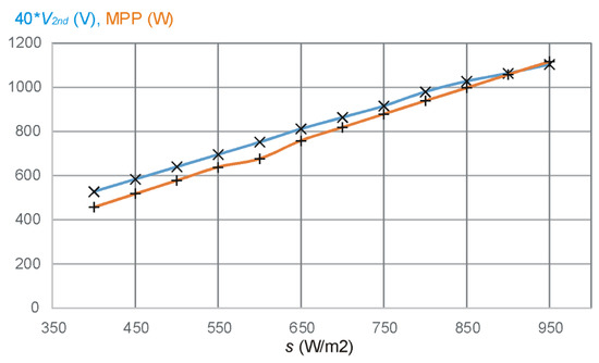
Figure 10.
Maximum power point MPP in W and scaled second harmonic amplitudes of the voltage ripples 40*V2nd in V for the proposed MPPT method versus solar irradiance s in W/m2.
Based on the analysis of measurements presented in Figure 10 the second harmonic of voltage ripple changes in a linear way due to the MPP change related to the solar irradiance value for elaborated MPPT method. Therefore it can be concluded, that the standard incremental conductance method effectiveness will vary depending on solar irradiances, and the increment step value for this method should be dynamically changed. These changes are provided by proposed method and for postulated growth of the power conversion effectiveness the power measurements for different states of the PvP were conducted. The measurements were done for the PvP emulation using groups of characteristics presented in Figure 11.
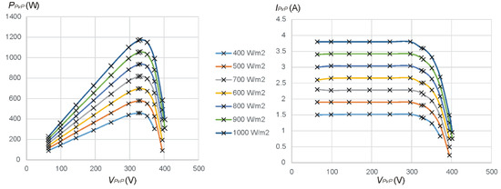
Figure 11.
Emulated PvP P-V and I-V characteristics obtained from the laboratory experiment for assumed solar irradiances s in W/m2 at temperature 298K.
Using PvP profiles represented by characteristics shown in Figure 11, the output power was measured in steady-state for the proposed MPPT method (INC1) and the standard incremental conductance method (INC2) with constant increment values tuned for different solar irradiances. As it is shown, the standard method with fixed step gives a result comparable to the MPP only for solar irradiance around the value for which it is tuned. For other irradiance values this tracker delivers lower energy values. The area depicted by the green in Figure 12 shows the power values for the standard incremental conductance MPPT method with different fixed steps. An information about the character of a PvP power derivative after voltage allows one to change the grid current in a continuous manner. As a consequence of it, the proposed MPPT allows power to be maximized over the entire range of solar irradiances in the presence of the voltage ripple.
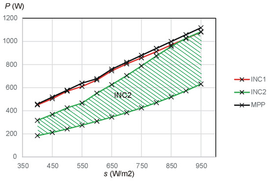
Figure 12.
Measured power in W delivered to the grid with proposed MPPT (INC1); with the incremental conductance MPPT (INC2) as an area determined for different fixed increments and maximum power point (MPP) versus solar irradiances s in W/m2.
The power losses for the proposed MPPT and the standard MPPT method measured for different voltage increments (dV1>dV2>dV3>dV4) were illustrated in a two-dimensional cylindrical coordinate system, where the full angle was divided into a 400–950 W/m2 range in a linear way and vector magnitude was connected with the difference between the maximum power point and measured power. In such a situation, established trajectories determine an area which is directly proportional to the power losses which can be observed in the irradiance range considered. Results of this analysis are presented in Figure 13.
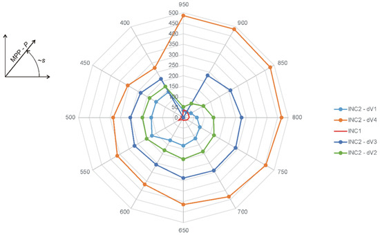
Figure 13.
Measured power losses in W delivered to the grid using: proposed MPPT (INC1); with the incremental conductance MPPT (INC2) for different values of the voltage increment (dV1, dV2, dV3, dV4) under solar irradiances s ranging from 400 to 900 in W/m2.
Based on Figure 13, the area depicted in red is the lowest, which indicates the most accurate power tracking using the proposed method in a wide range of solar irradiances. The voltage ripples caused by the DC to one-phase AC system conversion result in a large deviation to the MPP for the fixed step incremental conductance MPPT.
The proposed power converter with the incremental-conductance-based MPPT method was tested under variable temperature and standard solar irradiance. Encouraging features depicted above were confirmed by tests provided for external temperature range from 295 to 343K under standard solar irradiance level s = 1000 W/m2 using the proposed MPPT method and the incremental conductance method tuned for the assumed level. The PvP P-V and I-V characteristics refer to the tests being emulated in the power supply, and its measurement results are presented in Figure 14.
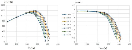
Figure 14.
Emulated PvP P-V and I-V characteristics obtained from the laboratory experiment for assumed temperatures in K for constant solar irradiance 1000 W/m2.
For each selected PvP characteristic under the discussed temperature range, the tracked power was measured. The results for the proposed (INC1) and standard (INC2) methods are depicted in Figure 15. As it can be observed, the power for INC1 MPPT method is always bigger than for the standard power tracker. The temperature rise results in greater effectiveness of the proposed solution due to the smaller MPP value under the same photovoltaic voltage and allows us to conclude that the effect of the voltage ripples is strongly reduced for an elaborated conductance-based MPPT method.
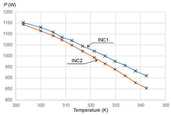
Figure 15.
Measured power of the MPPT: INC1—proposed conductance-based method; INC2—incremental conductance method tuned for assumed solar irradiance level versus temperature in K under constant solar irradiance 1000 W/m2.
4. Discussion
This paper describes the new maximum power point tracking system, which aims at ensuring the maximum photovoltaic power when the DC energy source is connected to a one-phase grid, especially for the flying onboard grid or for vehicle charging stations. As an effect of power balancing, the voltage ripples are observed on the DC side, which avoids achieving maximal power using the standard incremental conductance MPPT method due to constant voltage incrementation. The conductance-based power tracking method was adopted. and a new solution was elaborated and experimentally tested. The tracked power was measured for different environmental conditions, such as solar irradiance and temperature, and compared with the traditional MPPT method. By comparing the incremental based method, the corresponding experiment verification also shows salient advantages of the proposed conductance-based method as follows:
- (1)
- The steady-state power delivered to the grid effectively tracks the maximum power point under variable solar irradiances and temperature. In case of the trackers operating based on the voltage increment, the MPP is achieved only for tune point. When the environmental conditions are changing, the optimal operation point changes too; then, the traditional trackers with fixed voltage step cannot operate with maximal power. This is a result of variable amplitude of the voltage ripple and is connected with second harmonic of the voltage observed on the DC side.
- (2)
- Using the MPPT methods with fixed voltage steps, such as the perturb and observe method or the incremental conductance method, the grid current reference value oscillates around the MPP in steady-state. Then, the MPP achievement is more accurate when the voltage increment is smaller. When voltage ripples, the voltage increments must be properly big, which results in large steps of a reference current. In the case of the proposed conductance-based method, the reference current is calculated continuously, reducing voltage ripple’s impact.
- (3)
- The power losses related to the operation point being different to the MPP are minimized using continuous current referencing in the proposed MPPT method by voltage step size elimination.
Summarizing, the results obtained from experiments are sufficient to establish the maximum power tracking PvP system for a one-phase onboard system, as it minimalizes the voltage ripple effect. The elaborated MPPT method can be implemented in other renewable energy sources and grid systems; for example, the three-phase system. The observed features allow one to make more effective systems and should initiate further research. Adaptive and hybrid constant time change studies are planned in order to minimize the variable components in the calculated current.
Funding
This project is financed by the Ministry of Science and Higher Education of the Republic of Poland within the “Regional Initiative of Excellence” program for years 2019–2022; project number 027/RID/2018/19; the amount granted: 11,999,900 PLN.
Conflicts of Interest
The author declares no conflict of interest.
References
- Huynh, D.C.; Dunnigan, M. Development and Comparison of an Improved Incremental Conductance Algorithm for Tracking the MPP of a Solar PV Panel. IEEE Trans. Sustain. Energy 2016, 7. [Google Scholar] [CrossRef]
- Radjai, T.; Rahmani, L.; Mekhilef, S.; Gaubert, J.P. Implementation of a modified incremental conductance MPPT algorithm with direct control based on a fuzzy duty cycle change estimator using dSPACE. Sol. Energy 2014, 110, 325–337. [Google Scholar] [CrossRef]
- Blazev, A.S. Photovoltaics for Commercial and Utilities Power Generation; Fairmont Press: Lilburn, GA, USA, 2013. [Google Scholar]
- Arum, S.; Grace, D.; Mitchell, P.; Zakaria, M.; Morozs, N. Energy Management of Solar-Powered Aircraft-Based High Altitude Platform for Wireless Communications. Electronics 2020, 9. [Google Scholar] [CrossRef]
- Sun Seeker Duo—First Two Seat Solar Powered Aircraft. Available online: https://www.solar-flight.com/sunseeker-duo (accessed on 15 March 2020).
- Aglietti, G.; Markvart, T.; Tatnall, A.; Walker, S.J. Solar power generation using high altitude platforms feasibility and viability. Prog. Photovolt. Res. Appl. 2008, 16, 349–359. [Google Scholar] [CrossRef]
- Malaver, A.; Motta, N.; Corke, P.; Gonzalez, L. Development and Integration of a Solar Powered Unmanned Aerial Vehicle and a Wireless Sensor Network to Monitor Greenhouse Gases. Sensors 2015, 15, 4072–4096. [Google Scholar] [CrossRef]
- Li, Z.; Li, Y.; Wang, P.; Zhu, H.; Liu, C.; Gao, F. Single-Loop Digital Control of High-Power 400-Hz Ground Power Unit for Airplanes. IEEE Trans. Ind. Electron. 2010, 57, 532–543. [Google Scholar] [CrossRef]
- Zhao, H.; Burke, A. An Intelligent Solar Powered Battery Buffered EV Charging Station with Solar Electricity Forecasting and EV Charging Load Projection Functions. In Proceedings of the 2014 IEEE International Electric Vehicle Conference, Florence, Italy, 17–19 December 2014. [Google Scholar]
- Kjær, S.; Pedersen, J.; Blaabjerg, F. A Review of Single-Phase Grid-Connected Inverters for Photovoltaic Modules. IEEE Trans. Ind. Appl. 2005, 41, 1292–1306. [Google Scholar] [CrossRef]
- Tang, Y.; Blaabjerg, F. Power decoupling techniques for single-phase power electronics systems—An overview. In Proceedings of the 2015 IEEE Energy Conversion Congress and Exposition (ECCE), Montreal, QC, Canada, 20–24 September 2015; pp. 2541–2548. [Google Scholar] [CrossRef]
- Krein, P.; Balog, R.; Mirjafari, M. Minimum Energy and Capacitance Requirements for Single-Phase Inverters and Rectifiers Using a Ripple Port. IEEE Trans. Power Electron. 2012, 27, 4690–4698. [Google Scholar] [CrossRef]
- Vitorino, M.; Alves, L.; Wang, R.; Correa, M. Low-Frequency Power Decoupling in Single-Phase Applications: A Comprehensive Overview. IEEE Trans. Power Electron. 2017, 32, 4. [Google Scholar] [CrossRef]
- Zhang, L.; Ruan, X. Control Schemes for Reducing the Second Harmonic Current in Two-Stage Single-Phase Converter: An Overview from DC-Bus Port-Impedance Characteristic. IEEE Trans. Power Electron. 2019, 34, 10341–10358. [Google Scholar] [CrossRef]
- Zhang, L.; Ruan, X.; Ren, X. Second Harmonic Current Reduction for Two-Stage Inverter with Boost-Derived Front-End Converter: Control Schemes and Design Considerations. IEEE Trans. Power Electron. 2018. [Google Scholar] [CrossRef]
- Shi, Y.; Liu, B.; Duan, S. Low-Frequency Input Current Ripple Reduction Based on Load Current Feed-Forward in Two-Stage Single-Phase Inverter. IEEE Trans. Power Electron. 2016, 31. [Google Scholar] [CrossRef]
- Wang, W.; Ruan, X. A Modified Reference of an Intermediate Bus Capacitor Voltage-Based Second-Harmonic Current Reduction Method for a Standalone Photovoltaic Power System. IEEE Trans. Power Electron. 2016, 31. [Google Scholar] [CrossRef]
- Zhang, L.; Ruan, X.; Ren, X. One-Cycle Control for Electrolytic Capacitor-Less Second Harmonic Current Compensator. IEEE Trans. Power Electron. 2018. [Google Scholar] [CrossRef]
- Yuan, X.B.; Li, Y.D.; Chai, J.Y.; Wang, J. DC-link voltage ripple reduction for a transformerless modular wind generator system. In Proceedings of the 5th IET International Conference on Power Electronics, Machines and Drives (PEMD’10), Brighton, UK, 19–21 April 2010. [Google Scholar]
- Qin, Z.; Loh, P.; Blaabjerg, F. Benchmark of AC and DC Active Power Decoupling Circuits for Second Order Harmonic Mitigation in Single-Phase Inverters. IEEE J. Emerg. Sel. Top. Power Electron. 2016, 4. [Google Scholar] [CrossRef]
- Gu, B.; Dominic, J.; Zhang, J.; Zhang, L.; Chen, B.; Lai, J. Control of electrolyte-free microinverter with improved MPPT performance and grid current quality. In Proceedings of the IEEE Applied Power Electronics Conference and Exposition 2014, Fort Worth, TX, USA, 16–20 March 2014; pp. 1788–1792. [Google Scholar]
- Femia, N.; Petrone, G.; Spagnuolo, G.; Vitelli, M. A Technique for Improving P&O MPPT performances of Double Stage Grid-Connected Photovoltaic Systems. IEEE Trans. Ind. Electron. 2009, 56, 4473–4482. [Google Scholar] [CrossRef]
- Chen, H. Design of a New Type of Charging Station for Solar Electric Vehicle. In Proceedings of the 6th International Conference on Electronic, Mechanical, Information and Management Society, Shenyang, China, 1–3 April 2016. [Google Scholar] [CrossRef][Green Version]
- Sun, K.; Zhang, L.; Xing, Y.; Guerrero, J. A Distributed Control Strategy Based on DC Bus Signaling for Modular Photovoltaic Generation Systems with Battery Energy Storage. IEEE Trans. Power Electron. 2011, 26, 3032–3045. [Google Scholar] [CrossRef]
- Islam, H. Performance Evaluation of Maximum Power Point Tracking Approaches and Photovoltaic Systems. Energies 2018, 11. [Google Scholar] [CrossRef]
- Tofoli, F.; de Castro Pereira, D.; De Paula, W. Comparative Study of Maximum Power Point Tracking Techniques for Photovoltaic Systems. Int. J. Photoenergy 2015, 1–10. [Google Scholar] [CrossRef]
- Guo, Y.; Gawlik, W. Defining control strategies for photovoltaic reconnection in islanded microgrids. Elektrotechnik Inf. 2016, 133. [Google Scholar] [CrossRef]
- Shadmand, M.; Li, X.; Balog, R.; Abu-Rub, H. Model Predictive Control of Grid-tied Photovoltaic Systems: Maximum Power Point Tracking and Decoupled Power Control. IEEE First Workshop Smart Grid Renew. Energy 2015. [Google Scholar] [CrossRef]
- Vincheh, M.; Kargar, A.; Markadeh, G. A Hybrid Control Method for Maximum Power Point Tracking (MPPT) in Photovoltaic Systems. Arab. J. Sci. Eng. 2014, 39, 4715–4725. [Google Scholar] [CrossRef]
© 2020 by the author. Licensee MDPI, Basel, Switzerland. This article is an open access article distributed under the terms and conditions of the Creative Commons Attribution (CC BY) license (http://creativecommons.org/licenses/by/4.0/).