Article

Effect of Valve Opening Manner and Sealing Method on the Steady Injection Characteristic of Gas Fuel Injector

School of Automotive and Traffic Engineering, Jiangsu University of Technology, Changzhou 213001, China
*
Author to whom correspondence should be addressed.
Energies 2020, 13(6), 1479; https://doi.org/10.3390/en13061479
Submission received: 17 February 2020 / Revised: 5 March 2020 / Accepted: 17 March 2020 / Published: 20 March 2020
(This article belongs to the Special Issue Computational Analysis of Natural Gas Supply Chains)

Abstract

:
The steady-state injection characteristic of gas fuel injector is one of the key factors that affects the performance of gas fuel engine. The influences of different injection strategies, such as different injection angles and different injection positions, on the mixing performance in gas-fueled engine have been emphasized in previous literatures. However, the research on the injection characteristics of the gas fuel injector itself are insufficient. The three-dimensional steady-state computational fluid dynamics (CFD) models of two kinds of injectors, in different opening manners, and the other two kinds of injectors, in different sealing methods, were established in this paper. The core region speed, stagnation pressure loss and mass flow rate were compared. Additionally, the effective injection pressure (EIP) concept was also used to evaluate the injection efficiency of gas fuel injector. The simulation results show that the jet speed of the pull-open injector is higher than the push-open injector under the same operating conditions. The injection efficiency of the pull-open valve is about 56.0%, while the push-open valve is 50.3%. In general, the steady-flow characteristic of the pull-open injector is better than that of the push-open one. The injection efficiency of the flat sealing injector is 55.2%, slightly lower than the conical sealing method.

Graphical Abstract

1. Introduction

Compressed natural gas (CNG) is one of the most promising alternative fuels due to its rich resource and cheap price. Compared with a gasoline engine, a CNG engine can reduce carbon dioxide emissions by 25% [1] and greenhouse gas emissions by 10–20% [2]. The 2006 model year HONDA CIVIC GX, equipped with a CNG engine, was certified as a super ultra-low emission vehicle (SULEV) [3]. Additionally, the 2016 model year IVECO Cursor 11 CNG engine (11.1 L) reached the Euro VI emission standard [4]. However, natural gas has a lower energy density compared to diesel/gasoline. To provide a longer driving range for natural gas vehicles (NGV), liquefied natural gas (LNG) vehicles are proposed, with natural gas cooled to −162 °C at atmospheric pressure and stored in highly insulated cryogenic tanks [5]. LNG is usually vaporized out a cylinder and injected into the intake port or into the cylinder directly through the gas injector. CNG/LNG heavy-duty vehicles are normally spark plug engines, which are less efficient than conventional diesel engines working on a diesel cycle; they are about 17% less efficient but the emission benefit is around 10% [6]. On the other hand, dual-fuel vehicles (diesel and natural gas) have comparable efficiency as conventional diesel engines and combine the efficiency and torque characteristics of diesel engines while reducing the CO2 emissions by as much as 20% compared to gas engines [7]. It can be seen that the gas injection system will always be involved for CNG, LNG or natural gas/diesel dual-fuel engines.
According to the mode of gas injection system, these engines can be divided into two types: port fuel injection (PFI) and in-cylinder direct injection (DI) type. The DI mode can avoid the drop of volumetric efficiency, which is the disadvantage of a gas-fueled PFI engine. Thus, the former tends to have a higher engine power. However, the DI mode has some fatal disadvantages. The injector would be exposed directly to the combustion chamber under this mode. Thus, key parts of the injection system, such as the gas fuel injector, need the heat-resistant treatment to ensure work stability, which undoubtedly increases the manufacturing requirements. Moreover, the lubricating and cooling problems of direct CNG injector are remained unsolved currently [8]. Thus, the PFI mode will still be an important developing direction of gas fuel engines.
The gas injector is the ultimate component of any kind of gas fuel injection system for CNG, LNG and dual-fuel engines. The injector’s controllability and injection characteristics have a great influence on the engine performance. Currently, the driver of injectors is mostly solenoid, and the executing component is mostly in the form of a spherical or needle valve [8]. Such kinds of injectors are small in size and can be installed conveniently in the engine. However, its mass flow rate is quite low. In order to meet the gas fuel supply requirements of large-bore gas-fueled PFI engine, the injection pulse width was increased to 500 °C A, which was far beyond the intake stroke [9]. Therefore, the gas fuel injected was gathered in the intake port before the intake valve was opened for the PFI injection system, which would cause backfire in the intake port. More importantly, the injector’s control accuracy, working reliability and life will be seriously decreased because of the solenoid, whose control characteristic is poor [8].
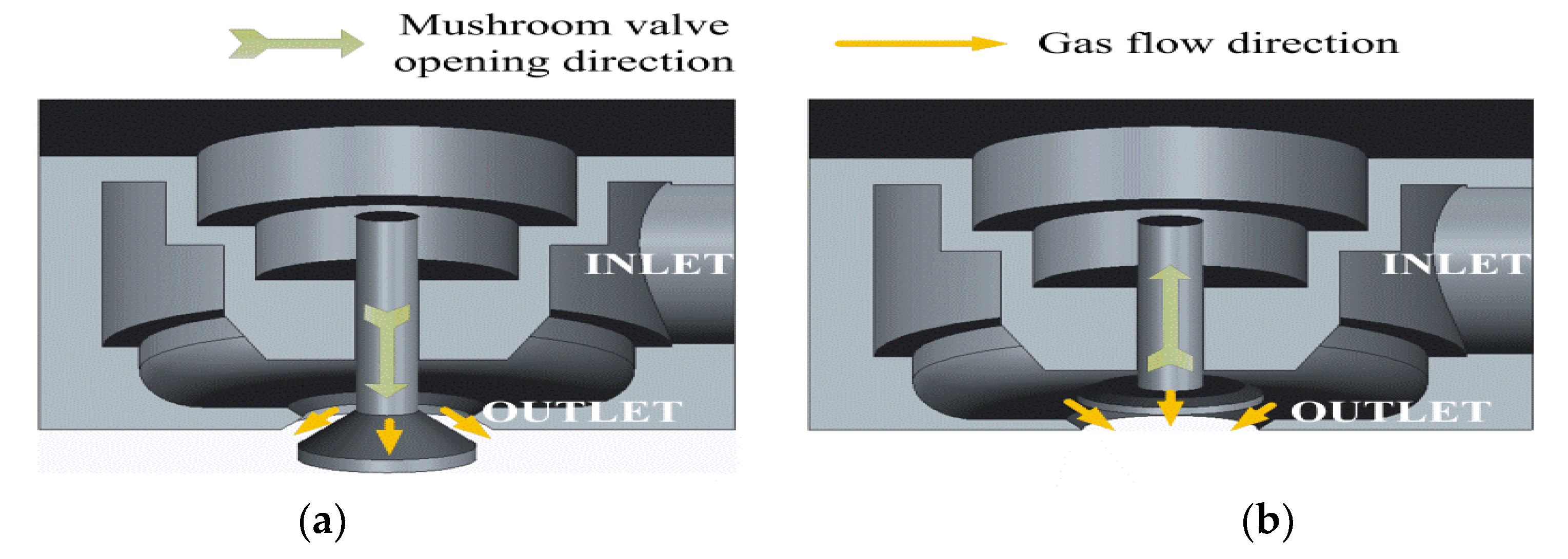
In order to solve the low injection-rate and the low controlling accuracy problems of the traditional injector, the authors had designed one new kind of gas fuel injector [10]. The moving-coil electromagnetic linear actuator was used as the driver, because of its higher controlling accuracy and longer working life than solenoid. The mushroom type poppet valve was used as the executing component, because of its higher injection-rate and better sealing performance than spherical or needle valve.
For the traditional spherical or needle valve, considering that the valve is small and the outlet of the injector is usually round in shape, the virtual round-hole nozzle can be used to simplify the computational fluid dynamics (CFD) calculation process of the injection characteristic. The internal structure of the injector would not be taken into consideration. The influence of the injection strategy on the mixture formation and combustion process in a PFI natural gas rotary engine was studies using virtual round-hole nozzle [11]. This simplified method was also used to simulate the mixing process in the dual-fuel (diesel-CNG or diesel-hydrogen) engine to optimize the gas injector orientation [12]. The interaction between the gas fuel jet and the air movement in the intake port was focused, while the injection characteristics of the gas injector itself were ignored. This situation is the same for some DI studies. The in-cylinder high pressure ratio CNG jets issued at freestream and impinging conditions were studied [13]. The effects of injection parameters, combustion chamber geometry and engine speed on mixing performance have been studied [14]. All of the above studies needed to set the spray pattern and outlet mass flow before CFD calculation because they did not take the internal structure of the injector into consideration, which will affect the simulation accuracy.
In recent years, a small number of researchers have begun to pay attention to the injection characteristics of the gas fuel injector. The sensitivity of the mixture formation process to nozzle type, injection pressure and injection timing was investigated [15]. Three kinds of nozzles, namely a simple circular nozzle and a 45° and 55° hollow cone push-open nozzle, were compared. It was concluded that the impingement-induced mixing performance was more dominant with the circular nozzle and the 45° hollow cone nozzle. The umbrella jet formed by the push-open type injector was studied in a DI engine [16]. It was found that to control the injection shape of the umbrella jet was difficult because it would be easily affected by the pressure and speed outside the outlet. These few research articles on the type of injector pay more attention to the influence on the mixing uniformity or stratification effect, and have not conducted in-depth research on the injection characteristics of the gas fuel injector itself.
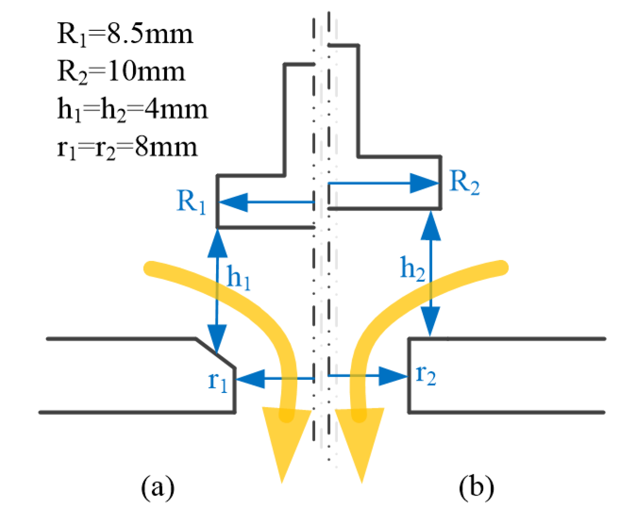
In the present study, the steady-state injection characteristics of two kinds of injectors with different opening manners (push-open and pull-open poppet valve) were emphasized using the FLUENT code. Furthermore, the effects of the valve profile and valve sealing method on the jet pattern are revealed. Section 2 presents the calculation model, the grid independency study and the steady-state experiment to verify the mesh independence. Moreover, the effects of the valve profile, valve opening manner and sealing method are analyzed in Section 3. This paper is concluded in Section 4.

2. Numerical Model and Experimental Verification

2.1. Computational Domain

To highlight the effect of an injector’s structure on the gas jet characteristics, only the internal flow area of the injector and one atmospheric outflow domain, with an appropriate size, were taken into account in the present study, although the gas fuel injector should be installed on the intake manifold for the PFI engine. For the naturally aspirated PFI engine, the pressure in the intake manifold was close to normal atmospheric pressure during the gas fuel injection process. Thus, the outflow domain was set as the standard atmospheric pressure 0.101315 MPa. It should be pointed out that the pressure values given in this paper are all gauge pressures, which are relative to the atmospheric pressure. For all cases, the gas fuel inlets are set as the pressure inlet boundary and the gas outlets are set as the pressure outlet boundary.
The outflow characteristics of the push-open poppet valve are closely related to the valve profile [17]. For this reason, two kinds of common valve profile, the flat valve and conical valve, are selected, as shown in Figure 1a and Figure 1b, respectively. They have exactly the same valve body and valve lift (4 mm). Their injection stagnation pressures were set to 0.4 MPa (gauge value).
Secondly, in order to analyze the effect of valve opening manner, two gas injectors (with a push-open and pull-open valve opening manner, respectively) are chosen as shown in Figure 2. The reason for selecting these two kinds of injection devices is that they are commonly used for the PFI or DI gas fuel engine [15]. They have the same body structure, the same outlet diameter (16 mm), the same valve maximum lift (4 mm) and the same stem diameter (6 mm). Their injection stagnation pressures were set to 0.1 MPa. For the above-mentioned valve size, this pressure was high enough to meet the gas supply requirements of the large-bore (190 mm) gas fuel engine according to the author’s previous study [10].
Finally, the influence of conical and flat sealing methods on jet characteristics of the pull-open poppet valve was analyzed. The flat sealing method is more suitable for the gas injector because of its lower alignment requirement. These two sealing methods are shown in Figure 3. The diameter of conical poppet valve was taken as 17 mm, while the diameter of flat valve was 20 mm. Their injection stagnation pressures were also set to 0.1 MPa.

2.2. Grid Independence Study and Experimental Verification

One of the most important variables affecting the numerical model ability to calculate the flow correctly is the number of grid points across the injector exit. In order to exclude the influence of the intake port wall on the gas jet pattern, the jet export zone was set as a cylinder-shaped chamber with a diameter of 70 mm and a height of 150 mm.
Although the exit diameter of the poppet valve is much larger than that of traditional needle valve, the length scale difference between the poppet valve and the jet export zone is still in the order of 10. Thus, it is necessary to have finer grids near the valve exit, and coarser grids far from the valve. Moreover, to avoid numerical instability, the so-called “transition layer” should be located far from the injector’s exit.
The results of the mass fraction distribution, along the exit axis of the cylinder-shaped chamber and along the radial direction of cross section 10 mm downstream of the outlet at time 0.1 ms after injection, have been plotted against the size of the grid cells across the exit in Figure 4a,b, respectively. It could be seen that the mass fraction tends to be stable with a decrease in grid cell size. The 0.4 mm grid size will certainly give the best calculation accuracy when compared to the other sizes. However, it is also necessary to take the computation cost into account. For a grid size of 0.4 mm, nearly 3,000,000 grid cells were generated because of the fine grids near the injector’s exit and the transition layer in the atmospheric outflow domain. The huge number of cells easily leads to an exorbitant CPU-time (up to about 300 h for each case). For a grid size of 1 mm, there were about 1,200,000 grid cells. The run time is typically about 80 h for each case on an Intel core i7 computer.
In order to verify the grid independence above, a flow rate measurement platform is built as shown in Figure 5. The compressed air instead of CNG is taken as gas source for safety’s sake. The high pressure from the air compressor is reduced to 0.02MPa, 0.03MPa, 0.04MPa, and 0.05MPa respectively by a pressure regulator. The inlet/outlet pressure ratio is about 1.2, 1.3, 1.4 and 1.5 respectively. The volumetric flow rate of injector is measured by a vortex flowmeter. The experimental results are compared with simulation results (grid size 1mm) as shown in Figure 6. It can be seen that the difference between experimental value and simulation value is less than 3.1%. This suggests that the grid size 1mm is appropriate for grid-independent numerical simulation of CNG injection.

2.3. Numerical Model Method

According to the model verification results above, the grid size near the injection nozzle was taken as 1 mm and the grid size up to 3 mm was used in other areas. Moreover, to avoid numerical instability, a transition layer was used. As can be seen in Figure 7, the push-open conical valve case was taken as example to show the mesh work. The total number of grids was about 1.2 million for this case. All cases were calculated by a FLUENT code. The turbulence model verification refers to the author’s previous research results [18]. The effects of three kinds of RNS turbulence models on wall penetration jet penetration distance were analyzed: the standard k-ε model, RNG k-ε model and realizable k-ε model. Furthermore, the calculation accuracies of the standard wall function and non-equilibrium wall function were compared. The RNG k-ε two-equation turbulence model and the non-equilibrium wall function were used. The numerical convergence limit of energy equation was set to 10−6, and the convergence limits of the other equations were set to 10−4.

3. Numerical Results and Discussion

3.1. Effects of the Valve Profile

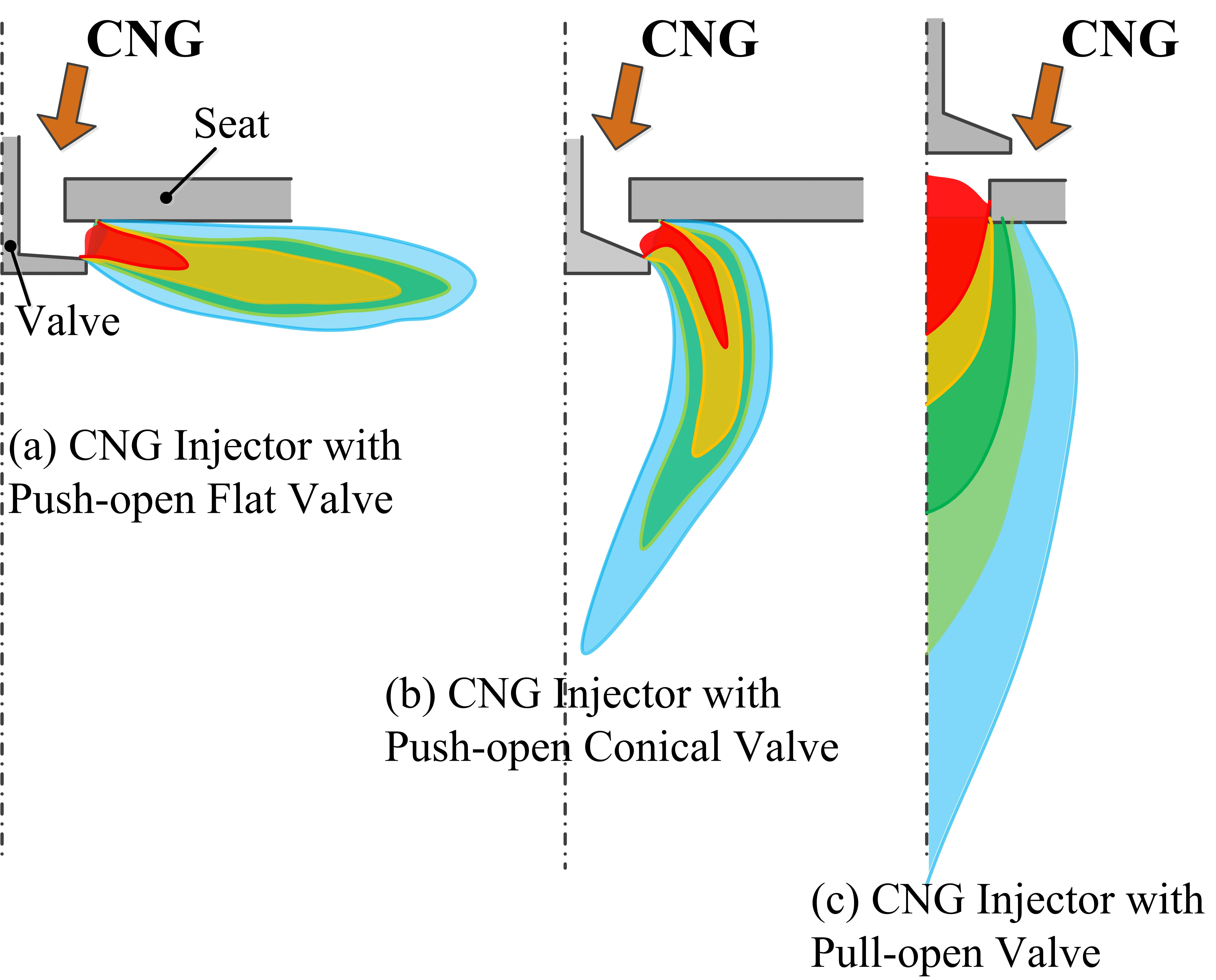
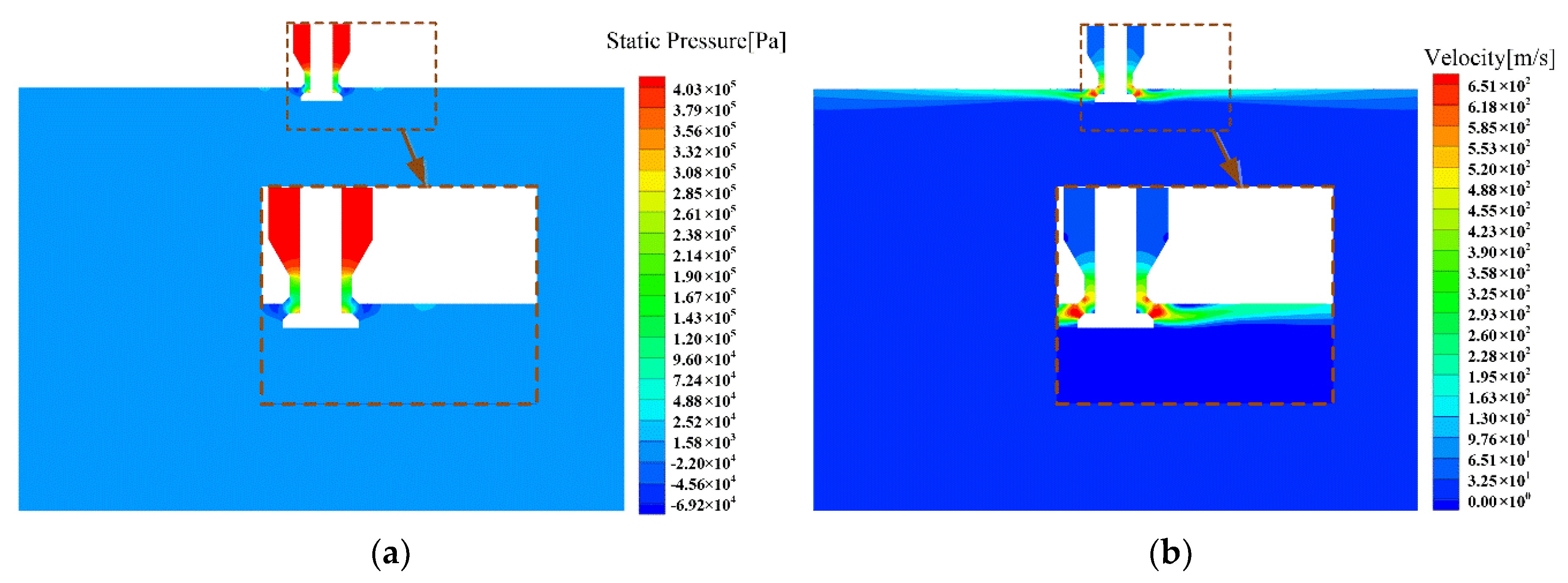
The steady jet patterns of flat (type A) and conical (type B) push-open poppet valve are shown in Figure 8 and Figure 9, respectively. It is obvious that the jets of these two kinds of push-open poppet valves are utterly different from each other, coinciding with the results obtained from the literature [11]. As shown in Figure 8, the expansion wave is formed at the corner near the valve body, with a drop of pressure. The supersonic jet is blocked by the flat valve, and then the jet direction is changed. This phenomenon is similar to the jet Coanda effect. A low-pressure area is created near the upper wall, which leads to the jet being drawn to the wall and ejected along the radial direction. Thus, the supersonic jet turns along the body bend, and diverges in the radial direction.
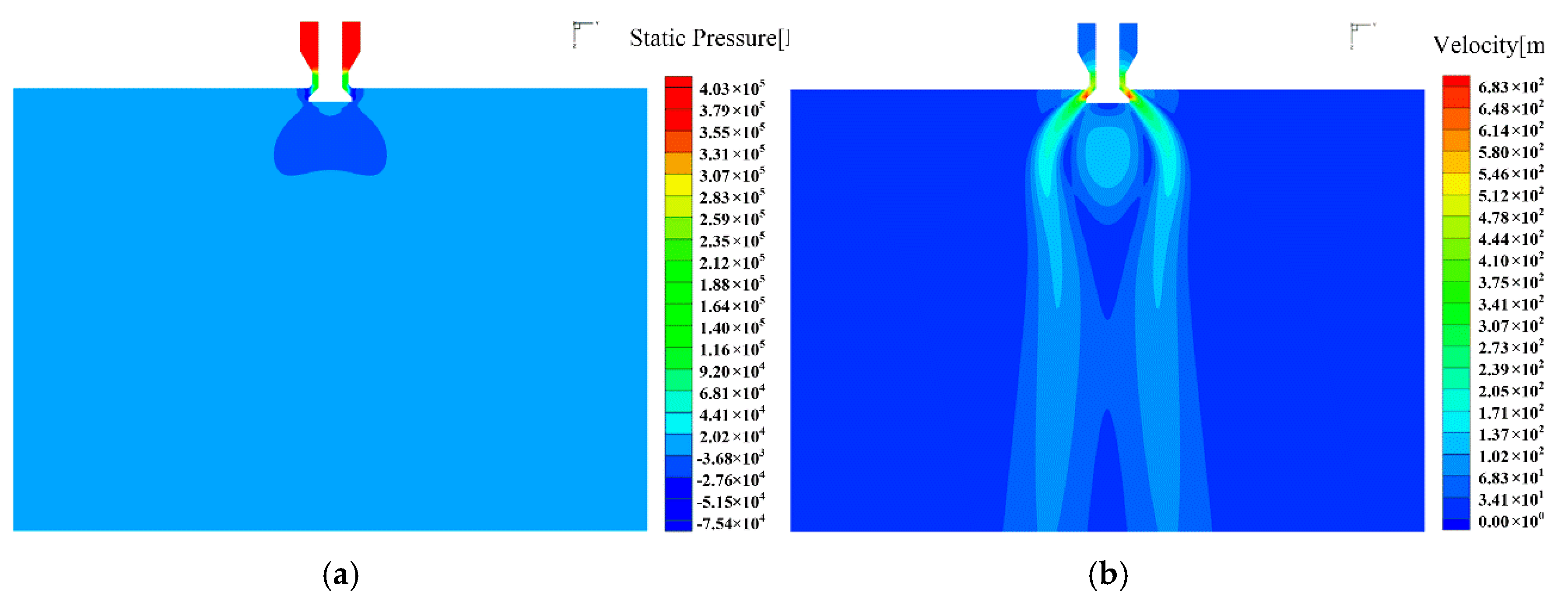
However, for the conical valve, the gas fuel supersonic jet flows along the valve profile rather than along the body bend. Moreover, a low-pressure area is formed near the side and bottom face of poppet valve. As a result, the supersonic gas jet is attracted to the direction of the outlet axis.
According to the results of literature [19], with the increase of the inlet/outlet pressure ratio, it is easier to form the divergence phenomenon as shown in 
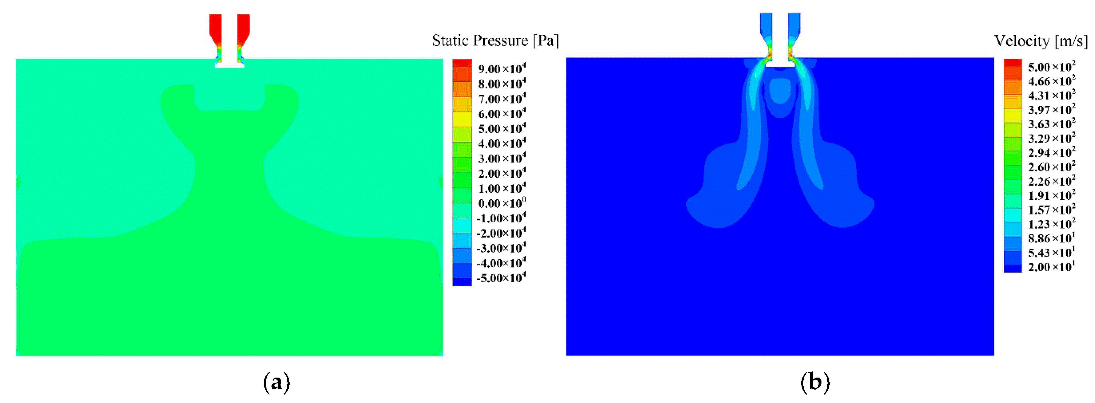
Figure 8. On the contrary, with the decrease of the pressure ratio, the jet tends to the outlet axis direction. To verify this law, the injection pressure of type A push-open valve was reduced to 0.1 MPa, and the steady jet patterns is shown in Figure 10. It can be seen that the supersonic gas jet will be attracted to the direction of outlet axis, according to what was expected. Thus, it can be guaranteed that the gas jet of type B push-open valve will be attracted to the outlet axis direction while the pressure ratio is less than 5:1.

3.2. Effects of the Valve Opening Manner

The steady jet patterns of the push-open and pull-open gas fuel injectors are presented in
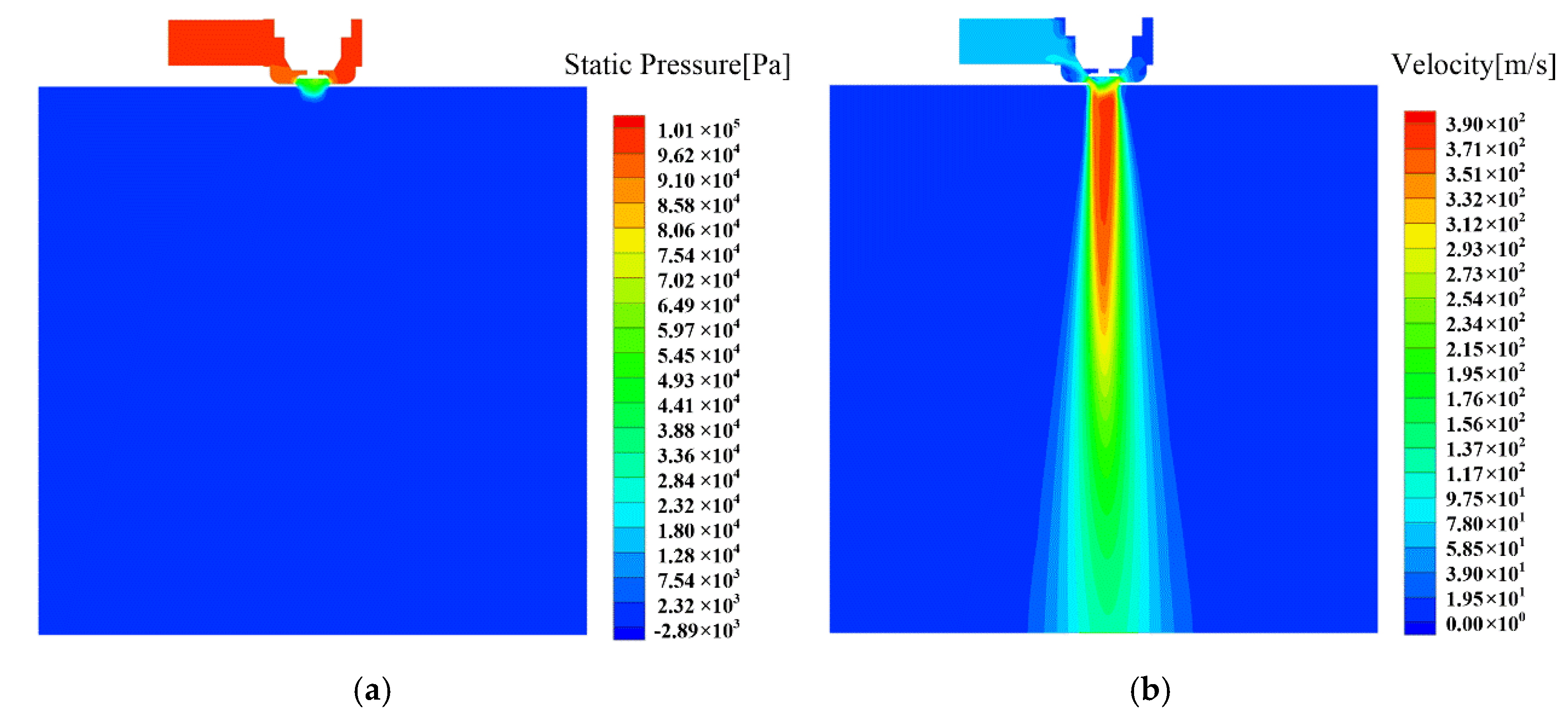
 Figure 11 and 
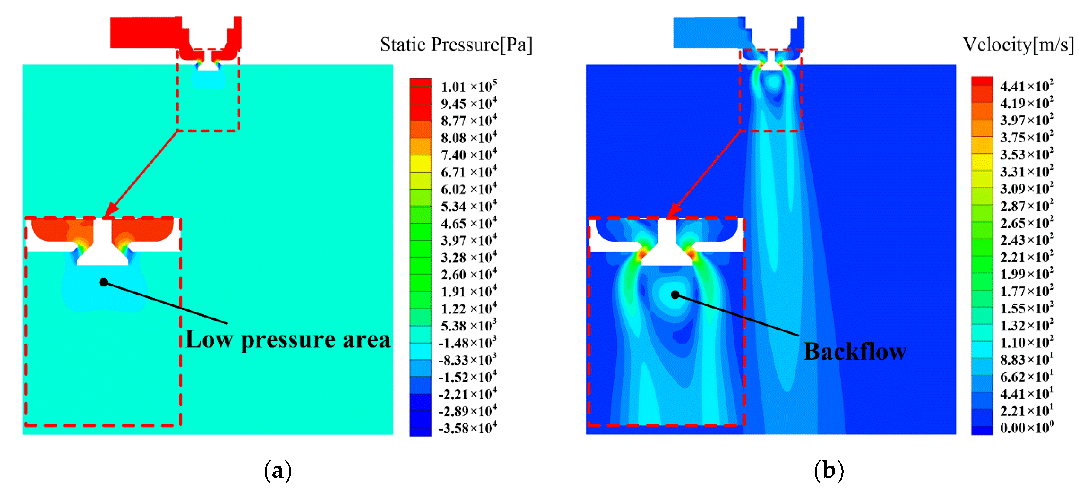
Figure 12, respectively. Obviously, they have distinct jet patterns. For the push-open injector, the fastest velocity appears in the gap between the popper valve and valve body. At the bottom side of the valve, an elliptical low-pressure area has been formed. As a result, vortexes appear. For the pull-open injector, as shown in Figure 12, the fastest area is located near the axis of cylinder-shape outflow zone. Different from the axisymmetric jet in Figure 8 and Figure 9, for these two cases, the jets slightly deviate from the axis due to the non-axisymmetric inlet position upstream.
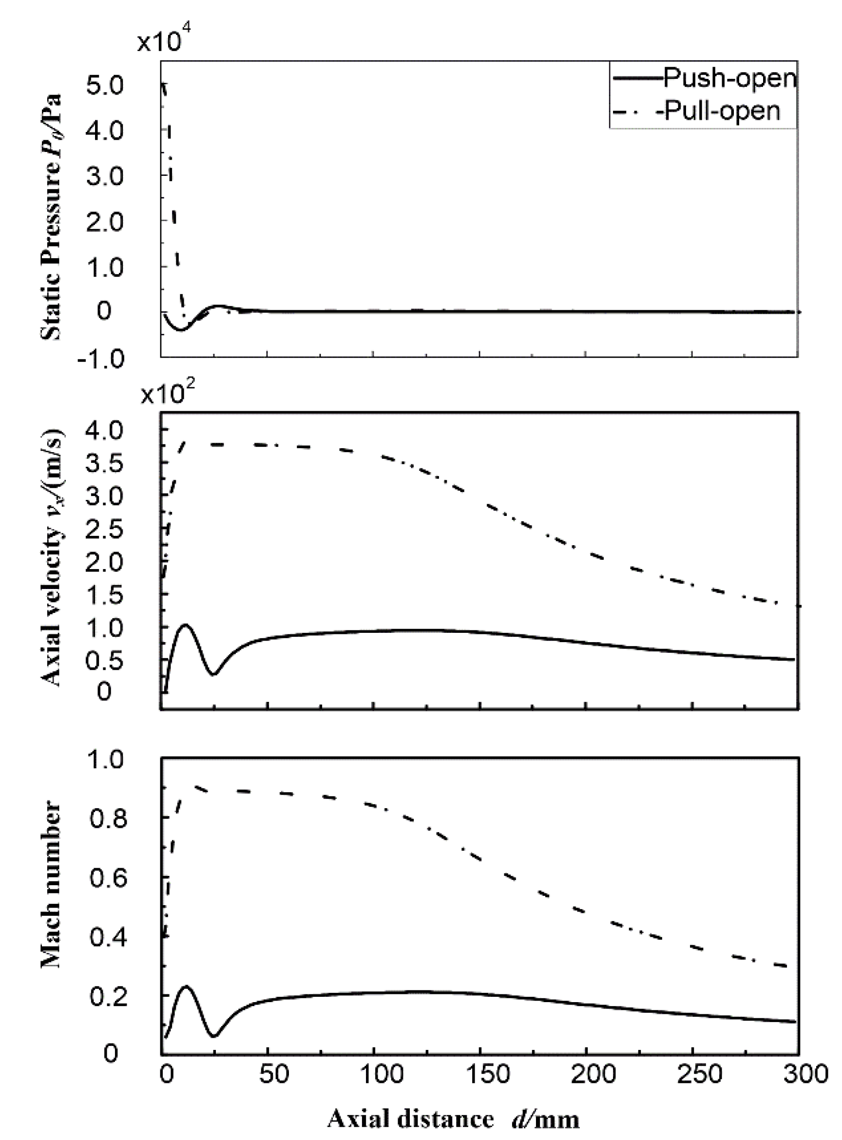
In order to analyze the injection characteristics in more detail, the stagnation pressure, velocity and Mach number distribution along the injector’s outlet axis are plotted in 
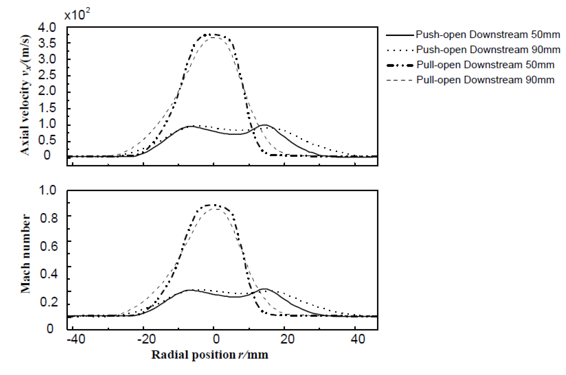
Figure 13. It can be seen that the axial velocity reaches the stable value within the range of 40–100 mm downstream the outlet for both two cases. The jet velocity of pull-open injector is higher than that of push-open injector. Additionally, the velocity decreases gradually due to the momentum diffusion after 100 mm downstream. Then, the axial velocity and Mach number radial distribution on the cross section 50 mm and 90 mm downstream outlet, within the stable range, are plotted in Figure 14. The maximum velocity of push-open injector deviates from the outlet axis. On contrary, the maximum velocity of the pull-open injector appears near the outlet axis. The mean velocity of the pull-open injector is much faster than that of the push-open injector. Thus, in the aspect of injection velocity, the pull-open injector shows a better performance.
There will be a considerable stagnation pressure loss when the gas fuel passes through injector. According to the results of literature [19], the actual jet velocity of one injector was completely subsonic under the inlet/outlet pressure ratio 4.06:1, while the theoretical velocity calculated according to the one-dimensional isentropic flow relationship was supersonic, as high as 1.6 Ma. This indicates that the stagnation pressure loss during injection process is high enough to affect the fundamental jet characteristic.
In order to analyze the difference of stagnation pressure loss between the pull-open and push-open valves, and to make the comparison more quantitative, based on the one-dimensional isentropic flow relationship, the effective injection pressure (EIP) is defined. EIP is the equivalent stagnation pressure required to produce the same centerline Mach number according to the one-dimensional isentropic flow relationship. Obviously, the value of stagnation pressure loss is equal to the actual supply pressure minus the EIP.
Considering that the centerline Mach numbers of both two injectors reached a stable value within the range of 40–100 mm downstream, as shown in Figure 13, the cross section 50 mm downstream was taken as the effective face to analyze the stagnation pressure loss of poppet valves. The EIP is defined in Equation (1):
p 0 , e f f p e = ( 1 + γ - 1 2 M e , e f f 2 ) γ γ - 1
where p0,eff is the effective injection pressure and Me,eff is the mass-weighted average of Mach number on the effective face under back pressure pe.
The pressure-based injection efficiency (IE), ep, is defined in Equation (2) as a parameter to compare the injection performance of different injectors quantitatively:
e p = p 0 , e f f p 0 , n o m ,
where p0,nom is the actual inlet supply pressure. It is obviously that the parameter IE is the ratio of EIP and the actual inlet supply pressure, and the value must be less than 100%. The higher the IE is, the higher the EIP is and the lower the stagnation pressure loss is.
Based on the definition of IE, the IEs of the push-open and pull-open injectors are 50.3% and 56.0%, respectively. Thus, in the aspect of stagnation pressure loss, the pull-open injector is also better than the push-open injector.
Lastly, the calculated steady mass flow rates and aerodynamic forces suffered by the valves of these two injectors were analyzed as shown in Table 1. The mass flow rate of the push-open injector is less than that of the pull-open injector in the case of the same other conditions. The lateral forces suffered by the valve stems of two injectors have the same direction, opposite to the incoming flow. They have little influence on the valve moving process because they are significantly smaller than the force of the electromagnetic linear actuator (about 200 N) and valve movement friction force. In the aspect of axial force, these two injectors are almost the same. Thus, it can be concluded that the pull-open injector is better than the push-open one for its larger mass flow rate and higher injection efficiency.

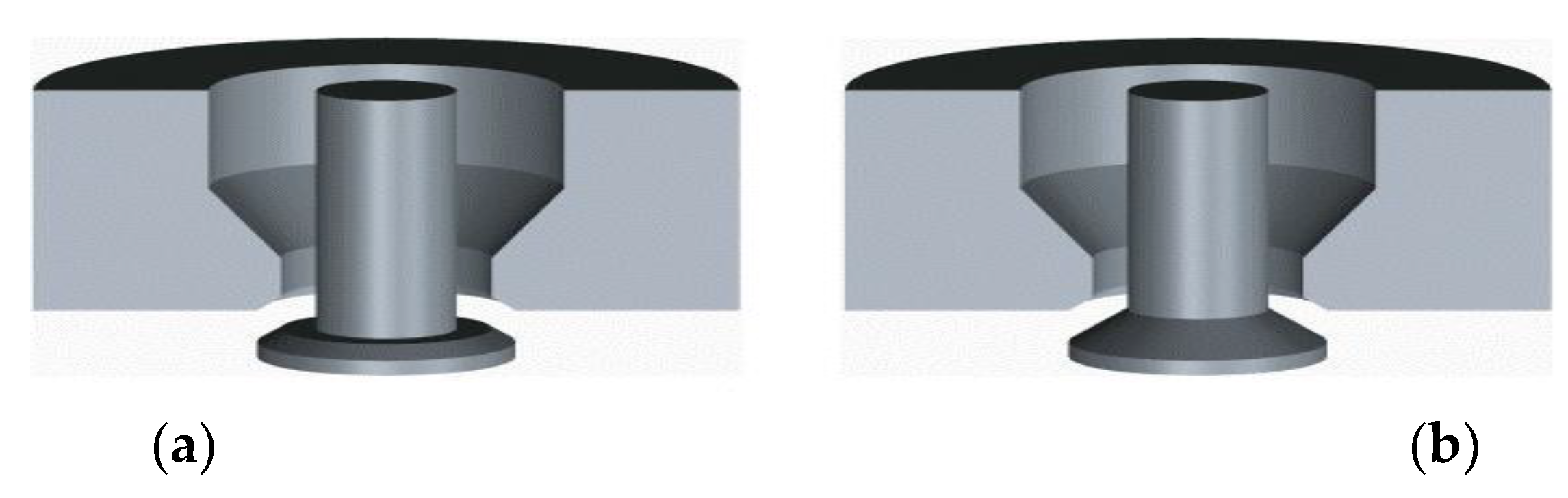
3.3. Effects of the Valve Sealing Method

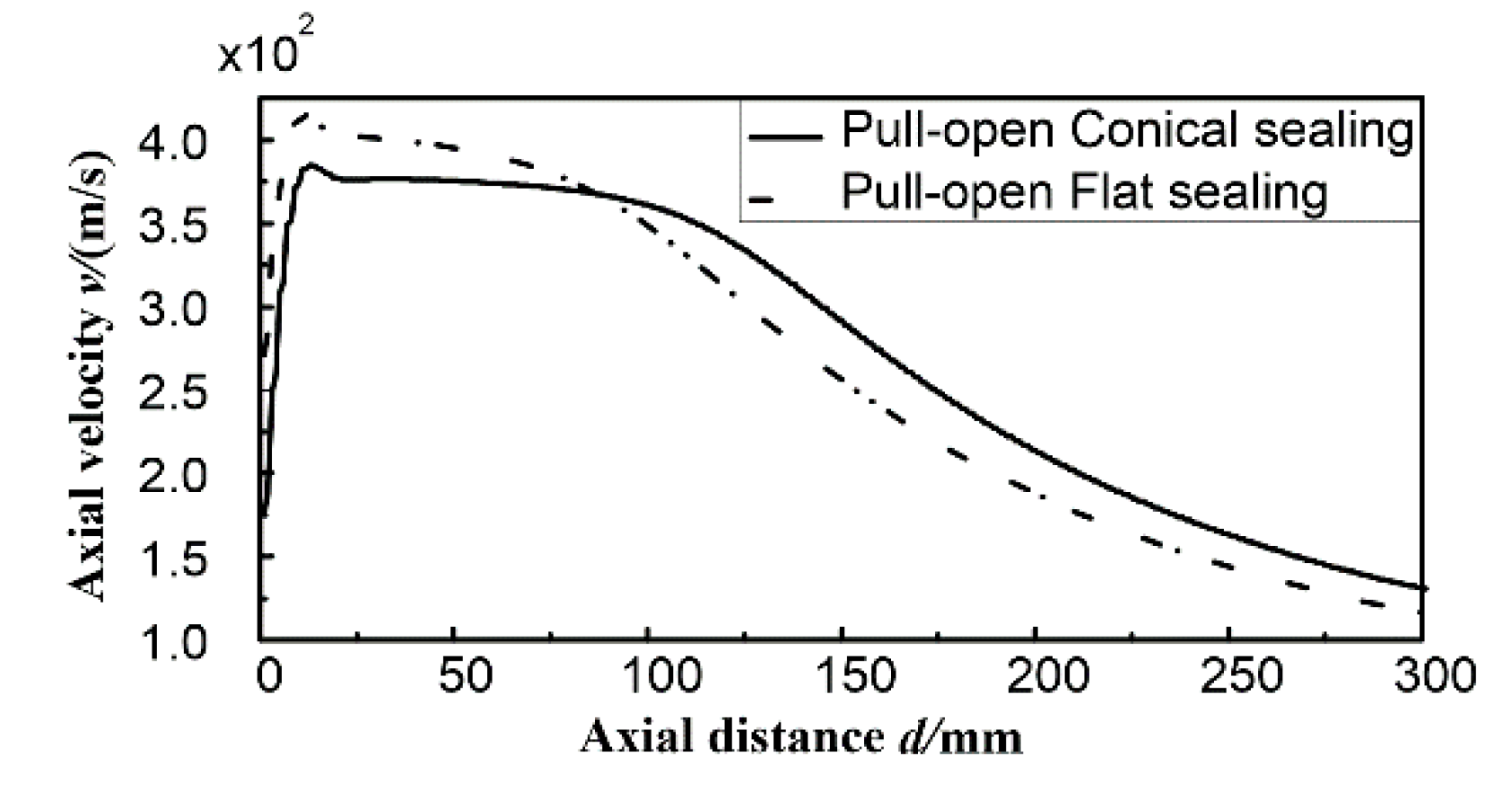
The axial velocity along the outlet axis of two types of pull-open injectors, with the conical sealing method and flat sealing method, respectively, is plotted in Figure 15. It can be seen that the injector with flat sealing method is slightly faster than that with conical way. The axial velocity reaches the stable stage in a 40–60 mm range downstream of the outlet and decreases gradually due to the momentum diffusion after the core area. Thus, the cross section 50 mm downstream is still taken as the effective face to analyze the stagnation pressure loss of the pull-open injector with a flat seal.
The IE of the pull-open injector with a flat seal was about 55.2%, slightly lower than that with a conical seal (56.0%). The mass flow rate of the flat sealing method was smaller (about 43.5 g/s), although its core velocity was faster. This led to a decline in IE. Moreover, its axial back force suffered by the valve disc was about 8.47 N, slightly larger than that of conical seal, because the flat sealing method had a larger valve disc than the conical sealing method. Thus, it can be concluded that the sealing method has little influence on the steady injection pattern of the pull-open injector.

4. Conclusions

The effects of the valve profile, valve opening manner and sealing method on the gas fuel injector’s steady flow characteristics was discussed in the present study. Additionally, a pressure-based injection efficiency was proposed to discuss the injection performance. Based on the analyses in the previous sections, we can conclude the following:
The push-open injector has a lower mass injection rate, slower core area speed and lower injection efficiency when compared with the pull-open injector, although the former is currently more commonly used in the case of high-pressure gas-fuel direct-injection engine because of its better sealing performance under back pressure.
In addition, the jet pattern of a push-open injector would be affected easily by the valve profile, not only affected by the pressure and flow speed of external environment. The flat profile would lead to a divergent shape jet, while for the conical profile the gas fuel would be attracted to the direction of the outlet axis because of the low-pressure area beneath the valve.
Lastly, different sealing methods seemed to have little influence on the jet pattern of the pull-open injector. The flat sealing method had a faster core speed than the conical sealing method, while this difference was assimilated by the declination of the mass flow rate.

Author Contributions

Methodology and software, T.W.; verification, L.Z. and Q.C.; resources, L.Z.; writing—original draft preparation, Q.C. All authors have read and agreed to the published version of the manuscript.

Funding

This research was funded by the National Natural Science Foundation of China, grant number 51305175; the Jiangsu Provincial Directional Plan Project of University Natural Science Research, grant number 18KJD470002; and the Changzhou Sci & Tech Program, grant number CJ20180032. The APC was funded by the Jiangsu Provincial Directional Plan Project of University Natural Science Research and the Changzhou Sci & Tech Program.

Conflicts of Interest

The authors declare no conflict of interest.

References

  1. Hekkert, M.P.; Hendriks, F.H.J.F.; Faaij, A.P.C. Natural gas as an alternative to crude oil in automotive fuel chains well-to-wheel analysis and transition strategy development. Energy Policy 2005, 33, 579–594. [Google Scholar] [CrossRef] [Green Version]
  2. Ou, X.; Zhang, X. Life-Cycle Analyses of Energy Consumption and GHG Emissions of Natural Gas-Based Alternative Vehicle Fuels in China. J. Energy 2013, 1, 1–8. [Google Scholar] [CrossRef] [Green Version]
  3. Karavalakis, G.; Durbin, T.D.; Villela, M.; Miller, J.W. Air pollutant emissions of light-duty vehicles operating on various natural gas compositions. J. Nat. Gas Sci. Eng. 2012, 4, 8–16. [Google Scholar] [CrossRef]
  4. Xu, B.; Rathod, D.; Yebi, A.; Filipi, Z.; Onori, S.; Hoffman, M. A comprehensive review of organic rankine cycle waste heat recovery systems in heavy-duty diesel engine applications. Renew. Sustain. Energy Rev. 2019, 107, 145–170. [Google Scholar] [CrossRef]
  5. Yeh, S. An empirical analysis on the adoption of alternative fuel vehicles: The case of natural gas vehicles. Energy Policy 2007, 35, 5865–5875. [Google Scholar] [CrossRef] [Green Version]
  6. A State-of-the Art Review on the Development of CNG/LNG Infrastructure and Natural Gas Vehicles (NGVs). Available online: https://futuregas.dk/wp-content/uploads/2018/08/FutureGas-WP3-Deliverable_Task-3.1.1_Review-natural-gas-vehicles_Final-002.pdf (accessed on 17 February 2017).
  7. Natural & bio Gas Vehicle Association (NGVA) Europe. European Natural Gas Vehicle Response. Available online: https://ec.europa.eu/clima/sites/clima/files/docs/0001/organisations/engva_en.pdf (accessed on 17 February 2017).
  8. Bircann, R.; Kazour, Y.; Dauer, K.; Fujita, M. Cold Performance Challenges with CNG PFI Injectors. SAE Tech. Paper 2013. [Google Scholar] [CrossRef]
  9. Payri, F.; Galindo, J.; Climent, H. Analysis of the Air-Fuel Mixture Control in Natural Gas Fuelled Turbocharged Engines. In Proceedings of the ASME 2008 Internal Combustion Engine Division Spring Technical Conference, Chicago, IL, USA, 27–30 April 2008. [Google Scholar]
  10. Wang, T.; Chang, S.; Liu, L. Influence of Injection Angle and Valve Opening Manner on Mixing Performance in a Large-Bore Port Fuel Injection Compressed Natural Gas-Fueled Engine. J. Eng. Gas Turbines Power 2016, 138, 122804. [Google Scholar] [CrossRef]
  11. Baratta, M.; Catania, A.E.; Pesce, F.C. Multidimensional modeling of natural gas jet and mixture formation in direct injection spark ignition engines—development and validation of a virtual injector model. J. Fluids Eng. 2011, 133, 1–14. [Google Scholar] [CrossRef]
  12. Chintala, V.; Subramanian, K. A CFD (computational fluid dynamics) study for optimization of gas injector orientation for performance improvement of a dual-fuel diesel engine. Energy 2013, 57, 709–721. [Google Scholar] [CrossRef]
  13. Rogers, T.; Petersen, P.; Lappas, P. Flow characteristics of compressed natural gas delivery for direct injection spark ignition engines. SAE Tech. Paper 2015, 3, 51–57. [Google Scholar]
  14. Yadollahi, B.; Boroomand, M. The Effect of Piston Head Geometry on Natural Gas Direct Injection and Mixture Formation in a SI Engine With Centrally Mounted Single-Hole Injector. SAE Tech. Paper 2011. [Google Scholar] [CrossRef]
  15. Keskinen, K.; Kaario, O.; Nuutinen, M.; Vuorinen, V. Mixture formation in a direct injection gas engine: Numerical study on nozzle type, injection pressure and injection timing effects. Energy 2016, 94, 542–556. [Google Scholar] [CrossRef]
  16. Baratta, M.; Rapetto, N.; Spessa, E.; Fuerhapter, A. Numerical and Experimental Analysis of Mixture Formation and Performance in a Direct Injection CNG Engine. SAE Tech. Paper 2012. [Google Scholar] [CrossRef]
  17. Baratta, M.; Catania, A.E.; Spessa, E.; Herrmann, L.; Roessler, K. Multi-dimensional modeling of direct natural-gas injection and mixture formation in a stratified-charge SI engine with centrally mounted injector. SAE Tech. Paper 2008, 1, 607–626. [Google Scholar] [CrossRef]
  18. Wang, T.; Chang, S. Effect of Injection Location and Multi-Hole Nozzle on Mixing Performance in a CNG-Fuelled Engine with Port Gas Injection, Using CFD Analyses. MATEC Web Conf. 2017, 95, 6003. [Google Scholar] [CrossRef] [Green Version]
  19. Kim, G.H.; Kirkpatrick, A.; Mitchell, C. Computational Modeling of Natural Gas Injection in a Large Bore Engine. ASME J. Eng. Gas Turbines Power 2004, 126, 656–664. [Google Scholar] [CrossRef]
Figure 1. Push-open gas fuel injector with a flat and conical valve: (a) Type A—Flat valve; (b) Type B—Conical valve.
Energies 13 01479 g001
Figure 2. Internal structure of the gas fuel injector: (a) Push-open injector; (b) Pull-open injector.
Energies 13 01479 g002
Figure 3. Structure of the gas fuel injector: (a) Push-open injector; (b) Pull-open injector.
Energies 13 01479 g003
Figure 4. Results of grid independency check (a) Mass fraction distribution along the exit axis; (b) Mass fraction distribution in the radial direction.
Energies 13 01479 g004
Figure 5. Testing platform of experimental verification.
Energies 13 01479 g005
Figure 6. Comparison of the results of experiment and CFD simulation.
Energies 13 01479 g006
Figure 7. Calculation domain and mesh (taking the push-open conical valve as an example).
Energies 13 01479 g007
Figure 8. The outflow pressure and velocity contour of the type A push-open injector. (a) Static pressure contour; (b) Velocity contour (inlet pressure, 4 bar).
Energies 13 01479 g008
Figure 9. The outflow pressure and velocity contour of the type B push-open injector. (a) Static pressure contour; (b) Velocity contour (inlet pressure 4bar).
Energies 13 01479 g009
Figure 10. The outflow pressure and velocity contour of the type A push-open injector. (a) Static pressure contour; (b) Velocity contour (inlet pressure 1bar).
Energies 13 01479 g010
Figure 11. The outflow contour of the push-open injector. (a) Static pressure contour; (b) Velocity contour.
Energies 13 01479 g011
Figure 12. The outflow contour of the pull-open injector. (a) Static pressure contour; (b) Velocity contour.
Energies 13 01479 g012
Figure 13. The pressure, velocity and Mach number distribution on the outflow centerline of injector.
Energies 13 01479 g013
Figure 14. Radial distribution of the axial velocity and Mach number on the section 50 mm and 90 mm downstream the outlet.
Energies 13 01479 g014
Figure 15. The velocity distribution on the outflow centerline of pull-open injector.
Energies 13 01479 g015
Table 1. Mass flow rates and forces suffered by the valves.
Injection ParameterPush-Open InjectorPull-Open Injector
Injection pressure (MPa)0.10.1
Mass flow rate (g/s)37.7246.35
Lateral force (N)0.200.05
Axial force (N)7.627.66

