Article

CFD Based Design for Ejector Cooling System Using HFOS (1234ze(E) and 1234yf)

1
Department of Applied Mechanics, Faculty of Mechanical Engineering, Technical University of Liberec, Studentská 1402/2, 46117 Liberec, Czech Republic
2
Department of Mechanical and Materials Engineering, Masdar Institute, Khalifa University of Science and Technology, Abu Dhabi, UAE
*
Author to whom correspondence should be addressed.
Energies 2020, 13(6), 1408; https://doi.org/10.3390/en13061408
Submission received: 18 February 2020 / Revised: 10 March 2020 / Accepted: 14 March 2020 / Published: 18 March 2020

Abstract

:
The field of computational fluid dynamics has been rekindled by recent researchers to unleash this powerful tool to predict the ejector design, as well as to analyse and improve its performance. In this paper, CFD simulation was conducted to model a 2-D axisymmetric supersonic ejector using NIST real gas model integrated in ANSYS Fluent to probe the physical insight and consistent with accurate solutions. HFOs (1234ze(E) and 1234yf) were used as working fluids for their promising alternatives, low global warming potential (GWP), and adhering to EU Council regulations. The impact of different operating conditions, performance maps, and the Pareto frontier performance approach were investigated. The expansion ratio of both refrigerants has been accomplished in linear relationship using their critical compression ratio within ±0.30% accuracy. The results show that R1234yf achieved reasonably better overall performance than R1234ze(E). Generally, by increasing the primary flow inlet saturation temperature and pressure, the entrainment ratio will be lower, and this allows for a higher critical operating back pressure. Moreover, it was found out that increasing the degree of superheat for inlet primary flow by 25 K improved the entrainment ratio by almost 20.70% for R1234yf. Conversely, increasing the degree of superheat to the inlet secondary flow has a relativity negative impact on the performance. The maximum overall ejector efficiency reached was 0.372 and 0.364 for R1234yf and R1234ze(E) respectively. Comparing the results using ideal gas model, the ejector entrainment ratio was overestimated up to 50.26% for R1234yf and 25.66% for R1234ze(E) higher than using real gas model.

1. Introduction

Refrigeration is identified as an indispensable method that is widely used in many applications, including food storage, providing thermal comfort, and in the health care industry to preserve pharmaceuticals and medicines. The conventional vapor-compression refrigeration systems are mainly driven by electricity and are usually characterized by high energy consumption [1]. It was observed by the International Energy Agency in 2018 that the demand for air-conditioners worldwide is predicted to soar, resulting in an increase in the number of air-conditioners from 1.6 billion units today to 5.6 billion units by mid-century [2]. Therefore, there is a growing concern that the amount of electricity needed to power them will overload the electrical grids. Even though the need to reduce the cost associated with high energy consumption of conventional refrigerators has resulted in many developments in refrigeration systems such as more energy efficient compressors, there is a limit to which this can be achieved. In addition, there is an increase in global-warming emissions caused by refrigeration systems relying on fossil fuels and the use of harmful substances such as chlorofluorocarbons (CFCs) as refrigerants. In fact, the emissions from these systems also contribute to ozone depletion which is most likely to increase the demand for air-conditioning, especially for thermal comfort [2].
Compared with conventional systems, ejector refrigeration systems (ERS) are more attractive, especially as we become more energy conscious. ERS come with advantages such as simple mode of function, lack of moving parts in construction, low cost, long lifespan, in addition to simplicity of installation and maintenance. This refrigeration system utilizes an ejector, generator and a liquid pump in place of the compressor which is electricity driven [3]. For a low-grade heat source, the liquid pump may consume up to 1% of the supplied heat to the ejector system. Compared to other conventional systems of the same refrigerating capacity, the ejector system may consume only one fifth of electricity consumed by the other systems [4,5].
Coefficient of performance (COP) is one of the main parameters for measuring ejector efficiency. The cooling systems of the refrigeration system may be analyzed from the COP. There exists a healthy relationship between the COP and the entrainment ratio in ejector cooling systems such that systems with high COP have high entrainment ratios, which provide high cooling capacity. Generally, the efficiency of ejector cooling system is usually not high. This is due to the complex nature of fluid flow in the ejector system and thus makes it difficult to attain a high COP. In addition, conditions such as turbulent mixing of two streams, shock waves and supersonic flow also affect the COP negatively; otherwise, ejector refrigerator is more sustainable and a good competitor to many types of refrigeration systems [6].
The advantages of using ERS have resulted in many researchers trying to exploit different techniques to enhance ejector performance. An example of such technique is the computational fluid dynamics (CFD). Over the years, CFD has shown very promising potential of predicting experimental results and assisting in the design of tools to improve the operation of ejectors [7]. Despite this, most numerical models of ejector systems have been limited to ideal gas, and as such fluid flow at subcritical condition of real gas where vapor coexist with liquid in two-phase flow are not considered [8]. Also, CFD results have shown that using the ideal gas model the entrainment ratio turns to be lower than when the real gas. An underestimated value of 20%–40% of the ideal gas model has been reported [9].
In this paper, the baseline ejector model was simulated using the real gas model because the properties of HFOs deviate significantly from the ideal gas law, especially at higher pressures. For example, air could be treated as an ideal gas, because the deviation between the ideal gas and real gas of this fluid is not large [10]. Moreover, the efficiency of the ejector was calculated in both cases too. It should be noted that this ejector was designed to apply the drop-in methodology where the same ejector can be used for both HFOs (1234ze(E) and 1234yf) working at the same required operating temperatures.
The comprehensive CFD simulation was performed based on the NIST real gas model in order to increase the accuracy and consistency of the results, and this was used to model and design 2-D axisymmetric ejectors. Most researches applied hydrofluorocarbons while HFOs (1234ze(E) and 1234yf) are used in this paper as working fluid based on the regulation of the European Parliament and the EU Council No.517/2014 [11]. The CFD analysis covered the working conditions of R1234ze(E) and R1234yf at saturation points which has not been presented in ejector often. Furthermore, the effect of superheat degrees at the primary and the secondary flow, which was negligible in most of the research papers, ideal gas computational, performance map, and the efficiency of the ejector were also studied. The work from Mohamed et al. [12] was pertinent to this paper based on the CFD design of the ejector under real gas modelling in spite despite the use of a different solver and turbulent model.

2. Ejector Refrigeration Cycle

The ejector refrigeration cycle system operates on a similar principle as the Carnot cycle. However, for the ejector refrigeration cycle, supersonic ejector provides an alternative method for the required compression. Therefore, the mechanical compressor in Carnot cycle is replaced with components such as ejector, liquid pump, and heat generator. The working fluid for this system is divided into two; primary and secondary flow. The primary fluid enters a converging-diverging ejector nozzle where it expands, generates a very low pressure and subsequently accommodates a supersonic flow at the exit [13]. Due to a local pressure drop and tangential force that develop at the edge of the primary flow, the secondary fluid is sucked into the ejector mixing chamber and entrained with higher velocity. In the mixing chamber, part of the energy from primary flow in the form of kinetic energy is transmitted to secondary stream and another part converted into pressure energy. The rest of the energy from both streams is dissipated as heat due to friction and mixing. Afterwards, a normal shock wave is experienced followed by a moderate back pressure in the condenser, causing sudden pressure to increase and deceleration to subsonic flow. The compressed stream then enters the diffuser with intermediate pressure between the motive fluid featured by the primary pressure and the secondary pressure of the entrained flow with deceleration to convert its kinetic energy back into potential energy. The resulting mixed stream leaves to the condenser to reject the heat and condense to liquid. Part of the working fluid then pumped to the generator as the primary stream and the rest goes to the evaporator through the expansion valve where the heat load will be absorbed from the cooling space or products.
In the refrigeration cycles, the performance of the ejector can be analyzed by several parameters. The energy efficiency of the cycle can be quantified by assessing the COP. It is defined as the ratio between the cooling capacities at the evaporator to the gross energy input to the cycle. The ratio between the secondary flow mass flow rate and the primary flow mass flow rate has another important evaluation parameter called entrainment ratio (ω). This is because the entrainment ratio indicates the operational mode of the ejector.
For the duration of the critical mode (on design) of operation, both the primary and the secondary flow are choked upon reaching the maximum value, and it remain constant with a low range of back pressure. However, only the primary flow is choked at the sub-critical mode (off design), resulting in a change in the mass flow rate ratio with respect to back pressure. In the case of back flow mode, a reverse flow at the secondary flow is observed and the entrainment ratio declines to lower than zero. In addition, the compression ratio parameter (CR) (also called pressure lift) is a key indicator for the pumping power because it points out how effectively the pressure of the suction secondary stream can be increased and thus measure the cycle operative range. CR is defined as the ratio of the static pressure between diffuser exit flow and secondary flow. Another important dimensionless parameter is the expansion ratio ER defined as the ratio between the primary pressure to secondary pressure. Regarding the ejector efficiency itself (ηejector), it can be defined by ASHRAE as the ratio between the actual recovered compression energy and the available theoretical energy in the primary stream [14,15].

3. Numerical Model Descriptions
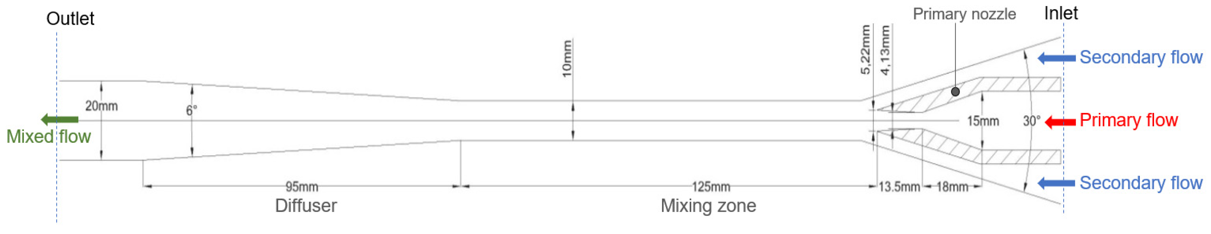
In the analytical approach such as the 1-D model, many assumptions needed to be considered such as the friction coefficients related to the mixing losses and isentropic efficiency, hypothetical throat inside the constant area, and the location of the shock waves. CFD does not require these assumptions or any correction factors from empirical results to accurate the model.

3.1. Ejector Design

The ejector remains the critical part that influences the ERS overall performance. Therefore, the geometry has to be sensibly determined. The simulated ejector was designed based on the study proposal of 30 KW ejector refrigeration system test stand at technical university of Liberec considering the guidelines obtained from Huang et al. 1999 [16] and preceding literatures to meet the system operational conditions, heat exchangers calculations and selecting of the working fluid. In addition, the geometry is designed to encounter the optimum working condition for both HFOs (1234ze(E) and 1234yf) refrigerants. These refrigerants are promising alternatives to fluorocarbons with low GWP and generally low flammability. Most importantly, they have a positively sloped saturation vapor curve where its entropy decreases along the upper limit curve known as the dry-expansion. In other words, the expansion process of the fluid at saturated vapor will end in the superheated vapor flow region which is useful to avoid condensation within the ejector [17,18].
The general schematic drawing of the ejector simulated in this paper is shown in Figure 1. In order to reduce the complexity and time-consumption due to real gas non-linearity, an axisymmetric two-dimensional ejector model was used. In contrast, the results of axisymmetric and three-dimensional simulation are similar [19].

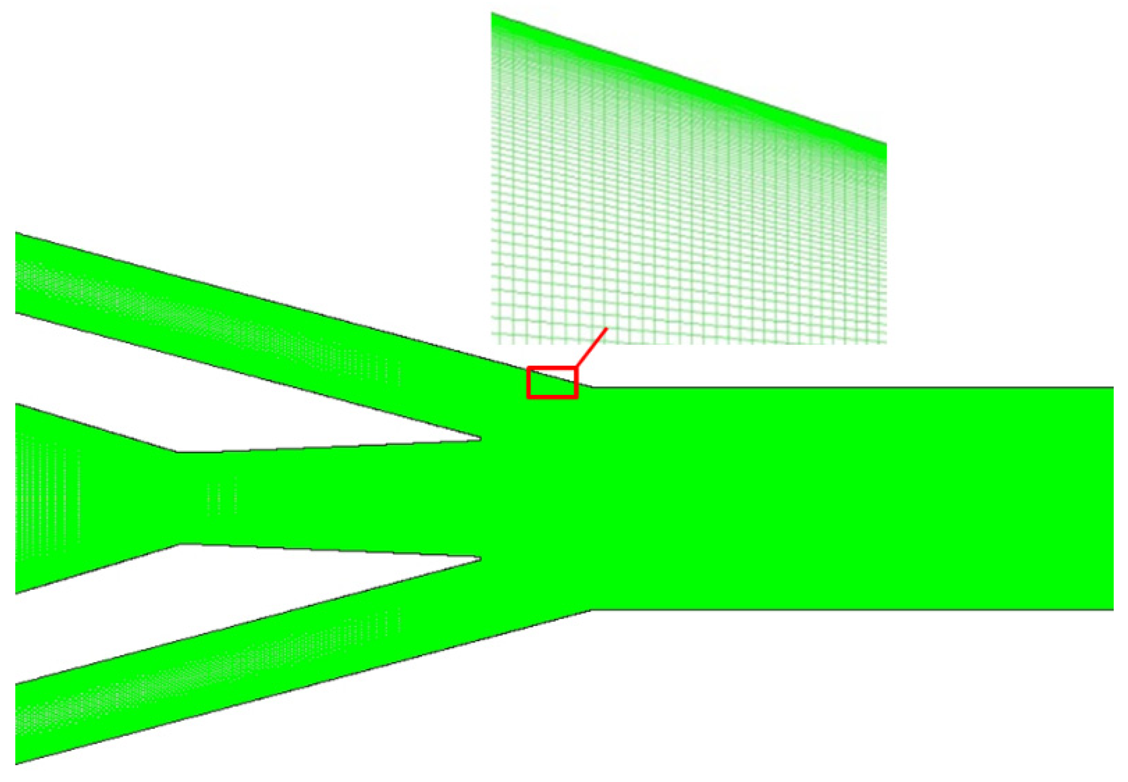
3.2. CFD Implementation

In this paper, the simulation was performed with real gas modelling approach using National Institute of Standards and Technology (NIST) fluid database (REFPROP v9.1) integrated in commercial Ansys Fluent R18.1 package [20]. In this respect, the governing equations are discretized using a control volume technique. The calculated axisymmetric space domain was divided as the final structured mesh into 274,241.00 and 270,182.00 number of elements for R1234yf and R1234ze(E) respectively. The reason for that difference is to account for y+ which in all cases was less than 5 as well as to capture the relevant phenomena and probe the physical insight that occur close to the wall.
The domain was quadrilateral meshing structural as shown in Figure 2, provides higher orthogonality and good quality mesh to obtain fast and stable convergence using the real gas model. To ensure gaining accurate numerical results, mesh sensitivity analysis was performed with four- and 15-times finer mesh on both working fluids as shown in Table 1. The analysis was conducted for the entrainment ratio (ω), primary and secondary mass flow rates (ṁp and ṁs), and the exit temperatures Tc. This indicated how the number of the mesh can affect the numerical results depending on further mesh density. It is shown from the table that the results are stable and there is no significant change with any further increase in the number of elements. Therefore, to perform the computation with less cost and time-consuming using NIST real gas non-linear model, case number 1 was selected to perform the numerical model analysis.
The k-ω SST turbulence model has been approved to be the most suitable for ejector calculation because of higher accuracy than another renormalization group RNG-based k-ε. In addition, it also shows better performances in term of stream mixing inside the ejector. Consequently, it has been selected as the turbulence model [1,3,21,22,23,24].
The simulation was performed under pressure-based coupled solver and the flow was set based on steady-state. For complex flows, it may be ideal to use the second-order upwind discretization since it leads to obtain good results in case of tetrahedral and quad/hex meshes [25]. Real gas models are usually characterized by complex equations, and therefore the solution seems to converge at a much longer time than ideal gas. Hence, to ensure convergence at a shorter time, the flow courant number was started from 1 and the under-relaxation factors values set at 0.1 with increasing values of superheat degrees for both inlet flow streams to higher than 30 K, and then after an adequate number of iterations, these parameters can be adjusted gradually to accelerate the convergence depending on the solution stability. It is easier to converge in the single-choke condition hence it is recommended to start within non-critical condition and then step by step increase the back-flow pressure to reach the critical condition. Most of the simulation converged to the residues up to 10−8 which is very difficult to reach if the density-based solver where used.

3.3. Boundary Conditions

The boundary conditions specify the dependent variables on the boundaries of the model to control the solution of the PDE. Basically, the simulated ejector is a passive device where the flow is confined and derived by its unique geometry. The boundary conditions were associated with two inlets linked with the motive flow from the generator and suction flow from the evaporator and one outlet-mixed flow which passed to the condenser. The walls are considered adiabatic. In this simulation, both refrigerant inlet conditions are set at saturated vapor. The primary flow stream temperatures Tp were tested at 87, 80, and 70 °C while the secondary flow stream temperatures Ts were at 6, 10, and 14 °C. Both flow streams were taken as the corresponding saturation pressure at their temperatures. Two pressure inlets were selected for the motive as the primary flow and the suction as the secondary flow entering the ejector and one outlet pressure for the mixed stream discharged to the condenser.

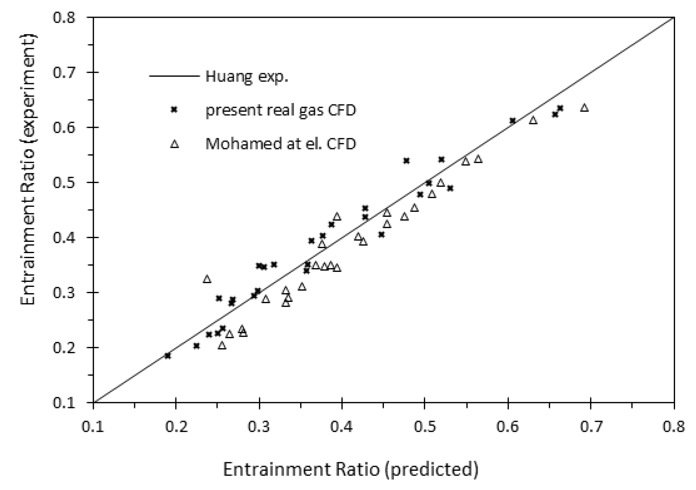
4. Numerical Validation

At the beginning of this work, the best available validation found was the experimental result from Huang et al. using 30 different cases at different ejector area ratios and similar operation conditions using results achieved at critical mode [16]. The reason for using Ref. 16 for validation is that the experimental data under various configurations and a wide range of operating conditions were clearly presented. The values of the entrainment ratio and critical back pressure were even specified by numbers. As well as the signature geometries were clearly mentioned and validated in the literature. The best turbulent model which can predict more precise results becomes the main challenge. Table 2 summarizes the test conditions along with the experimental and numerical entrainment ratio (ω), CFD primary and secondary mass flow rates (ṁp and ṁs), exit temperatures Tc, the error between the CFD model and the experimental data, as well as the number of mesh cells examined. The numerical work was performed under k-ω SST turbulence model using a pressure-based solver, and the inlet flow streams are set to be at saturated vapor. The numerical simulation was observed to converge when the residues of all governing equations fall below 1 × 10⁻⁸. The present calculated numerical model was able to predict the experimental entrainment ration within ±14% error as seen in Figure 3, while Mohamed el at. show a similar comparison with his CFD work using density-based solver and RNG k-ε turbulence model but with result error within ±20%.

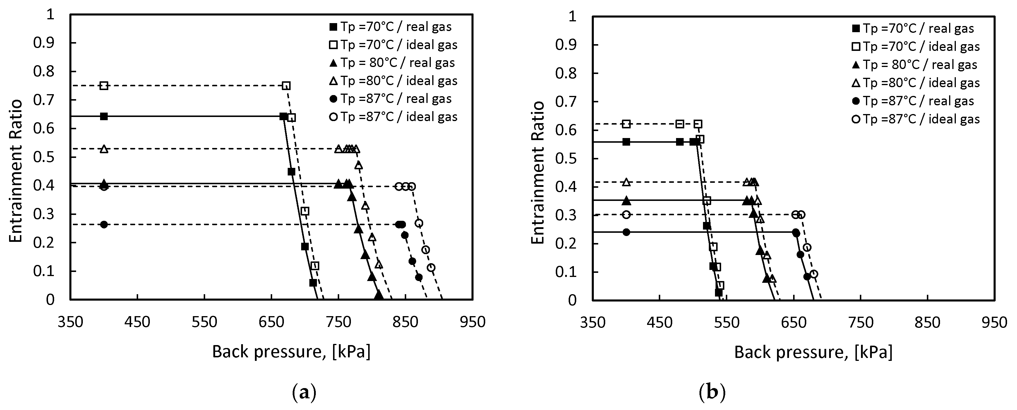
5. Comparison of Real and Ideal Gas Flow Results

The entrainment ratio results of the ejector in the case of working by ideal gas have been obtained in order to evaluate the difference between ideal and the used NIST real gas model. The approach of defining the physical properties of the ideal gas model is an important consideration. For that reason, the physical properties of the ideal gas model were specified based on the primary flow [26,27]. Therefore, viscosity, specific heat, and thermal conductivity were treated as constants throughout the calculation domain and depending on the operating conditions in each case, except the density was modelled using the ideal gas law.
The results show that the performance of the ejector was overestimated using ideal gas model as illustrated in Figure 4. For example, the entrainment ratio for R1234yf in ideal gas model at Tp = 70 °C and Ts = 6 °C was 16.78% higher than using real gas model. This ratio increased to 50.26% when Tp = 87 °C. Comparing to R1234ze(E) at the same previous working conditions, ω of the ideal gas model is about 11.40% higher than that of real gas model at Tp = 70 °C, but as the inlet primary flow saturation temperature increased to 87 °C, the difference becomes 25.66%. Researchers assumed in many reviews that simulations using the ideal gas model are able to predict sufficient results but, ironically, the comparison shows how it diverges from the actual real gas model results.

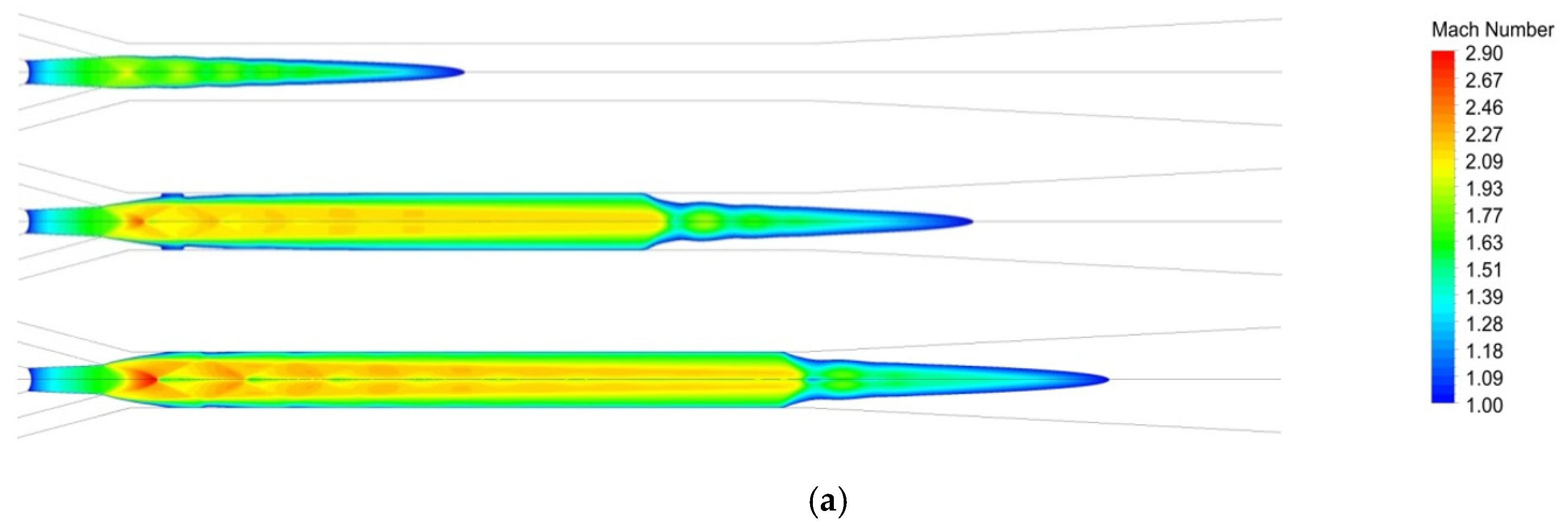
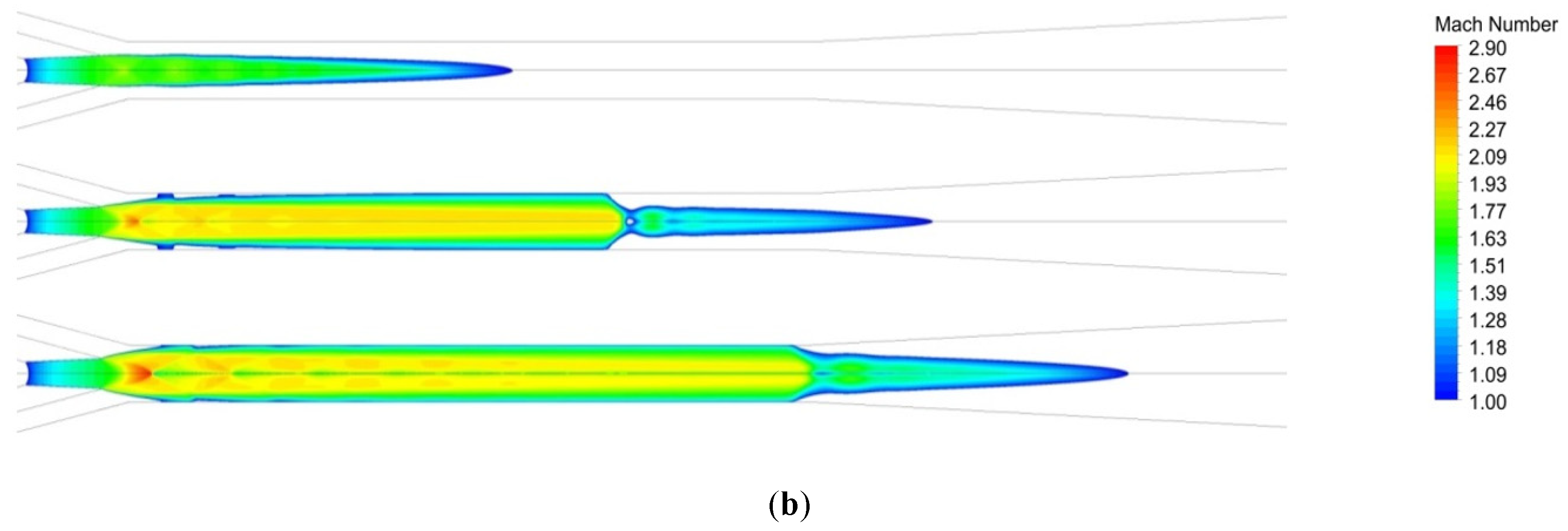
6. CFD Analysis of the Ejector

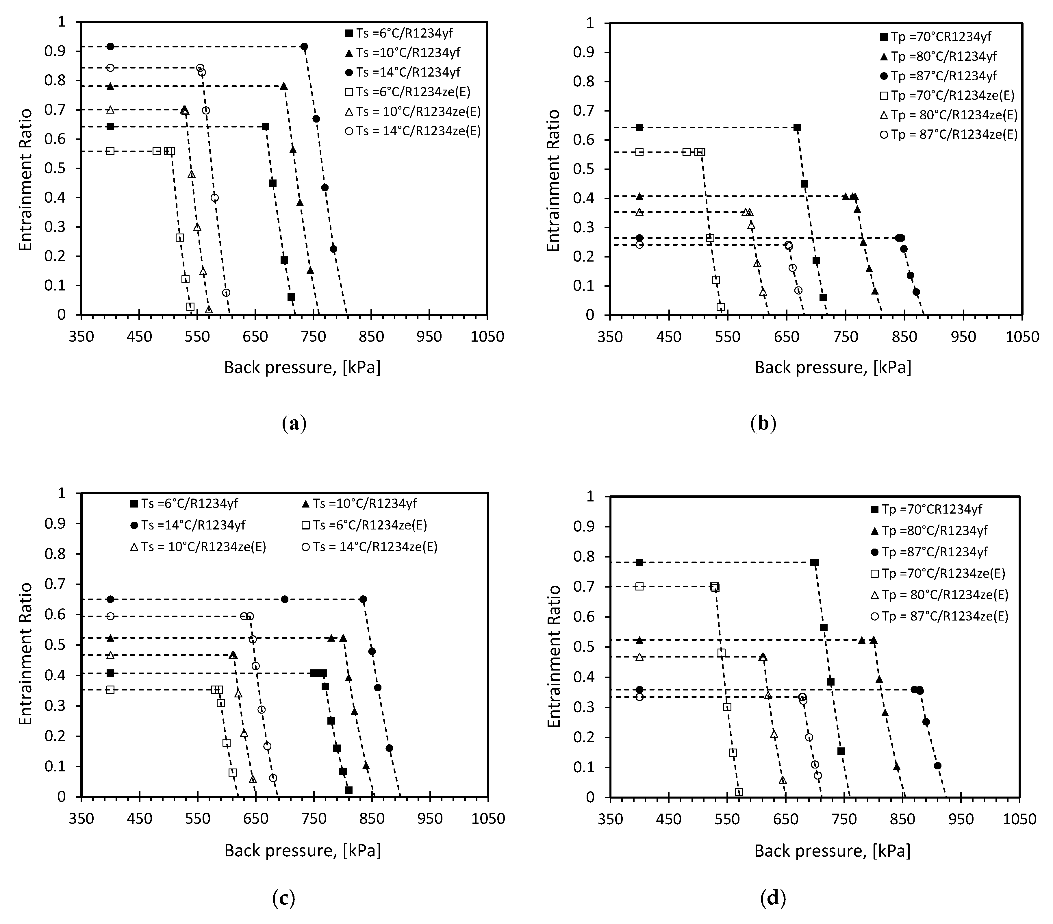
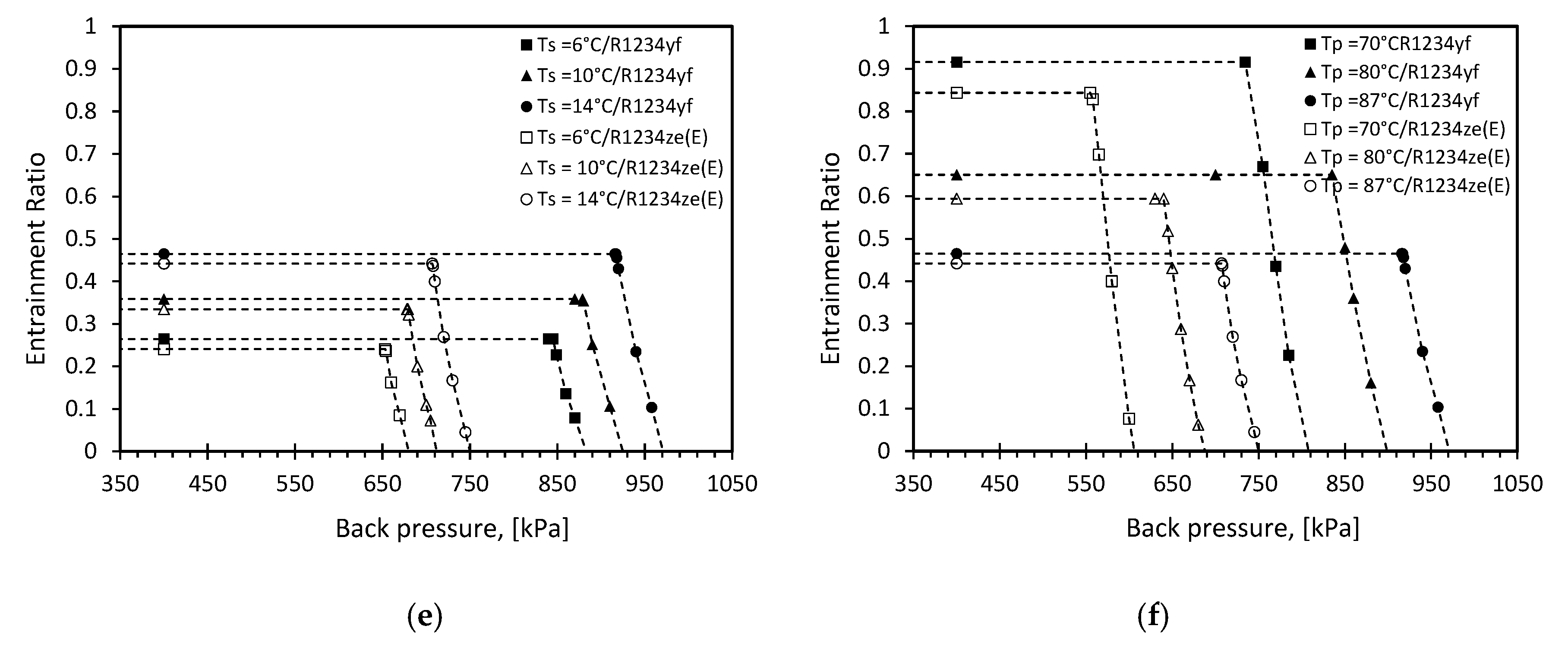
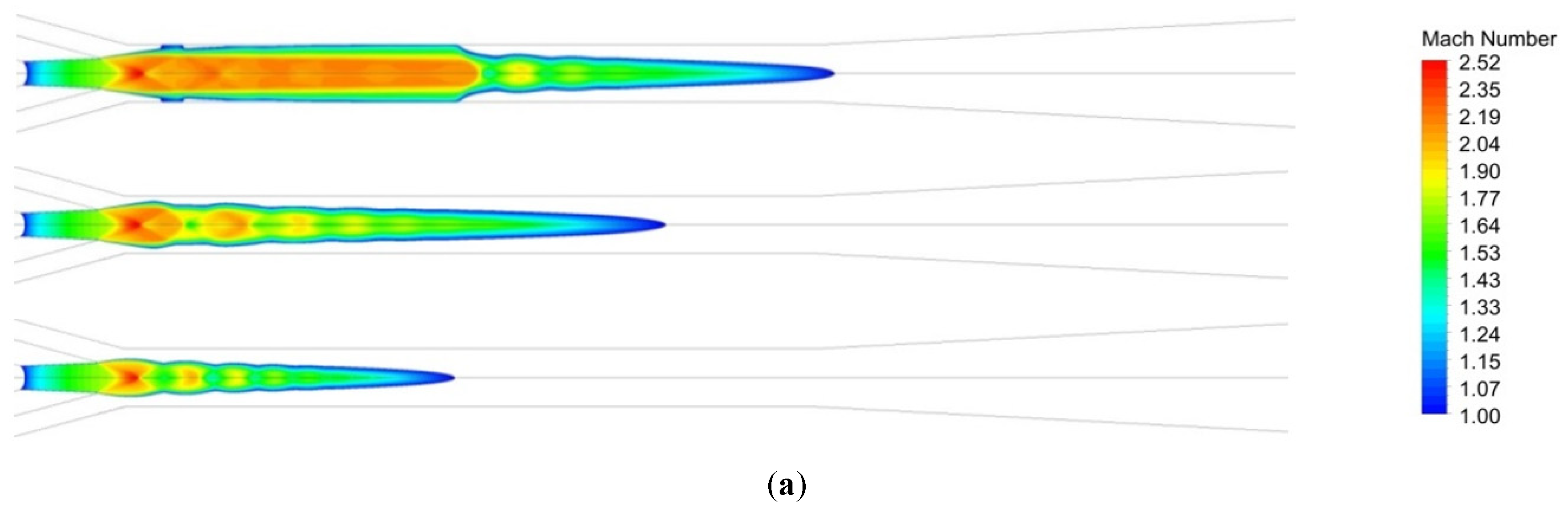
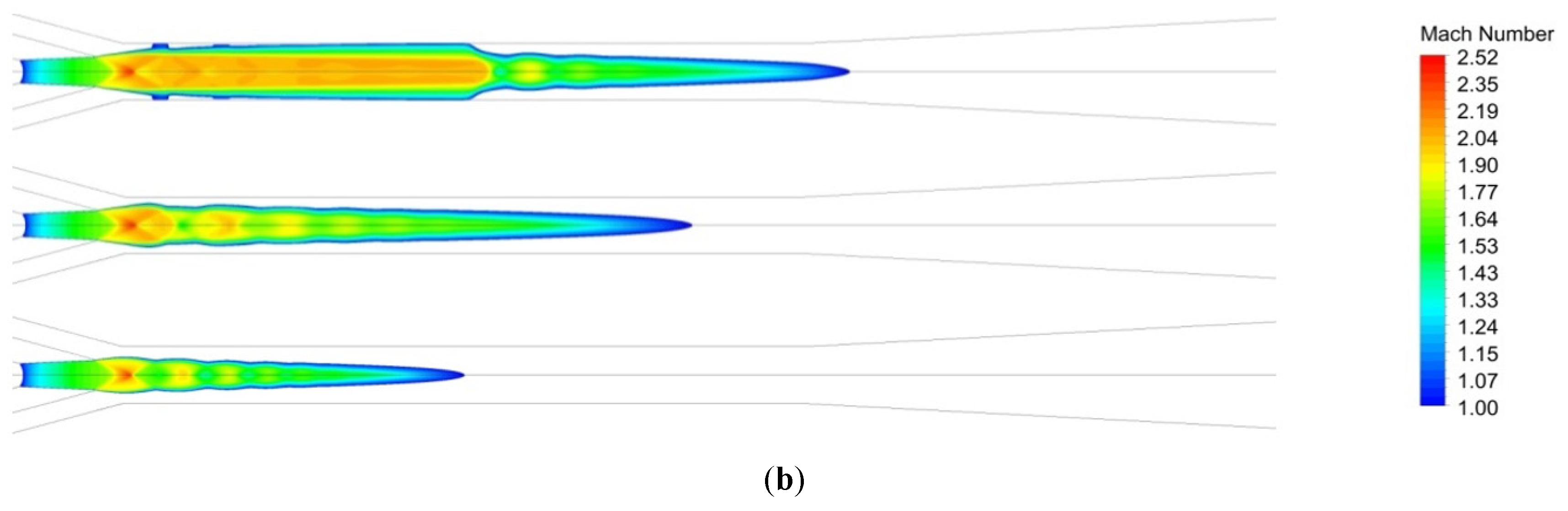
6.1. Effect of Operation Conditions

The primary and the secondary flow inlet to the ejector were examined under their saturation conditions. Three different primary temperatures (70, 80, and 87 °C) and entrained temperatures (6, 10, and 14 °C) were selected based on the working range of the designed ejector for both refrigerants. The details of the ejector performance were considered by investigating the characteristic curves for the ejector critical and subcritical modes because the ejector performance is assessed in terms of the energy recovered by the secondary flow with respect to the energy available in the primary flow. Figure 5 represent the effect of the primary flow as the desired amount of energy to accelerate and suck the secondary flow by converting the pressure energy of the primary flow into kinetic energy while mixing. Therefore, the entrainment ratio was predicted over the working range of back pressure. The dashed lines represent that the predicted data fit the performance curves while the markers show the numerical results.
It can be seen from Figure 5 that increasing the primary flow temperature caused a lower entrainment ratio and produced a higher critical back pressure. This is associated to the increase of the primary mass flow rate and serves to enlarge the expansion angle, causing a reduction of the annular effective area and increasing the resulting momentum of the mixed stream due to the higher velocity of the entrained stream attained. Therefore, the shock waves move downstream, and the ejector will operate at higher critical pressure. In addition, when the primary or secondary saturated flow temperatures is fixed, then the compression ratio will increase with increasing expansion ratio (ER), causing a lower entrainment ratio, and vice versa.
R1234yf represent higher entrainment ratio than R1234ze(E). At Tp = 70 °C and Ts = 14 °C the ejector works at the highest entrainment ratio. R1234yf recorded ω = 0.9158 where R1234ze(E) has ω = 0.8435. Decreasing the secondary temperatures to 10 °C and 6 °C also decrease ω by (14.72%, 17.71%) for R1234yf and (16.94%, 20.28%) for R1234ze(E) which is a decrease of about 13% back pressure. In other word, decreasing Ts at a fixed Tp will decrease the entrainment ratio because the secondary mass flow rate, ṁs, is decreasing whereas the primary mass flow rate, ṁp, is fixed. Moreover, the difference in ω between the refrigerants will be decreasing in case of increasing the fixed Tp. For example, at Tp = 70 °C the difference decreases by 8.57%, 11.47% and15.60% in case of Ts = 14 °C, 10 °C, and 6 °C respectively. When Tp = 87 °C, the difference in ω between the working fluids decreases to 4.91%. These differences are not varying that much in the case of increasing Tp at the fixing Ts, as represented in Figure 5.
The operating back pressure was affected by the inlet operating temperatures. With increasing both inlet saturated flow temperatures or even by increasing one of them, the critical mode for the ejector working with two refrigerants will increase. The on design working mode range is relatively higher in case of using R1234yf. Comparatively, it was found that at fixed Ts, the value of the critical back pressure Pc-cri increased by 100 kPa when Tp increased from 70 to 80 °C or from 80 to 87 °C, while Pc-cri for R1234ze(E) increased by 75 kPa at similar conditions.
In general, R1234yf has in the region of 23.50% higher critical back pressure than R1234ze(E) and higher ejector working back pressure range.
The maximum ejector efficiency at minimum energy cost should be considered when ejector cooling system is designed. This is linked with the energy required at the generator to increase the primary flow temperature to a certain limit where the ejection ratio reaches the maximum, nevertheless any extra energy added to the generator will have no significant effect and will be wasted. This analysis needs to be study at specific secondary and back pressure from the working fluid conditions to avoid testing the optimum case with all parameters. Figure 6 illustrates the contours of Mach number at different primary temperatures Tp inside ejector baseline for R1234ze(E) at Ts = 10 °C, Pc = 560 kPa and R1234yf at Ts = 10 °C, Pc = 730 kPa. Both refrigerants were represented at same Tp = 70, 80, 87 °C from top to bottom. It can be seen that increasing Tp, i.e., Pp at Tp saturation, will increase the oblique shock waves intensity and shift them upstream to the diffuser part. Furthermore, operating at higher Pp results in double-choking condition (critical mode) because the amount of energy that drives the entrained flow is enough to accelerate it to the choking state (sonic speed) achieving the peak value of the secondary mass flow rate and lift the flow to that particular back pressure. In addition, the size of the jet core is increased with higher Pp and, as a result, this has inversely proportional relation with the effective area (hypothetical throat) [28]. Consequently, it can be seen that the strong normal shock waves occur close to the diffuser at high Tp which is an indicator that the ejector is working in double-choking mode of operation but away from the critical point. On the other hand, when Tp is fixed and Ts is increased, then higher entrained flow energy and less amount of primary flow is required to accelerate the flow. At that point the ṁs will be increasing and hence the entrainment ratio. For this reason, it is recommended to work at higher secondary flow (saturation) temperatures. The primary nozzle operates in the under-expanded regime in all cases and the jet converged toward the ejector center when increasing Tp. It can be observed that the flow patterns are almost similar with slightly less intense shock waves for R1234yf.
Figure 7 illustrates the contours of Mach number for both working fluids at different back pressure. The top contours of the Mach number for both refrigerants represent the results at critical region where both primary and secondary flow are choked, and the entrainment ratio remains constant. The primary flow leaves the primary nozzle at supersonic velocity and the shock train can be observed along the centerline through the fluctuation of the static pressure before the mixing. A separation layer takes place between the primary and the secondary flow because of the velocity difference in between so that the entrained flow velocity will increase until the mixing take place at the constant throat area. The velocity become subsonic and the oblique shock waves take place due to the static pressure increase.
When the back pressure is increased to the critical value, the region of the subcritical mode starts, and that point called the critical back pressure where the Mach number contours represent at the middle contours in the figure. After that point, further increase in back pressure will cause a sharp decrease in the entrainment ratio till it reaches zero and a single choking appeared only for the primary flow as represented in the bottom contours. Afterwards, an additional increase in the back pressure will lead to the presence of reverse flow.
Moreover, it can be observed that increasing the back pressure will move the position of the shock waves towards the back of the primary nozzle direction and eliminate the existence of the shock waves when reaching the critical back pressure, as noticed in operating at back pressure of 613 kPa in case of R1234ze(E) and 801 kPa for R1234yf under the inlet condition of Tp = 80 °C, Ts = 10 °C. Regardless of the higher range of critical region for R1234yf, the contours of the Mach number and the shock waves look similar. Additional increase in the back pressure after the critical point will decrease the axial velocity of the mixed flow and move the oblique shock waves to the primary nozzle exit, where it disturbs the primary jet core to the limit when the primary flow could not expand, forcing it to flow reversibly to the entrained flow entrance.

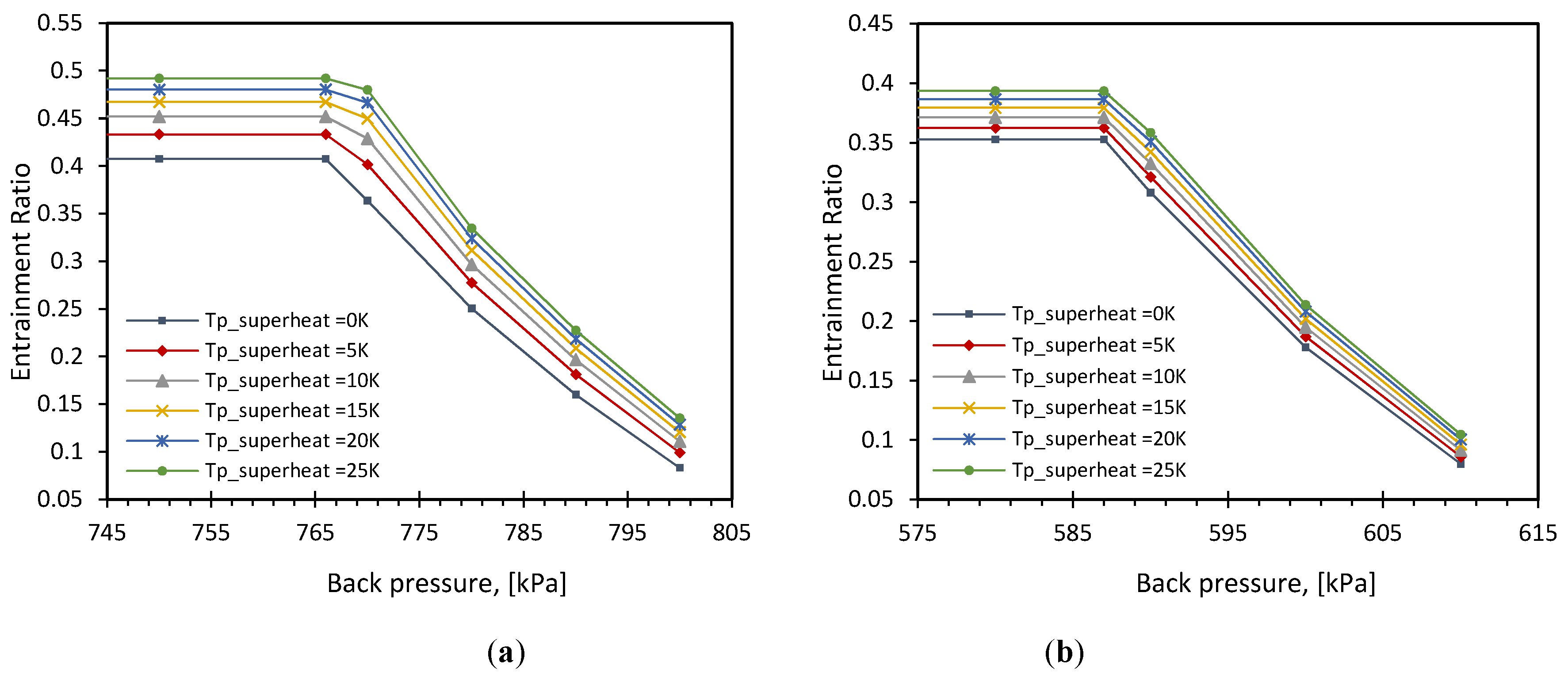
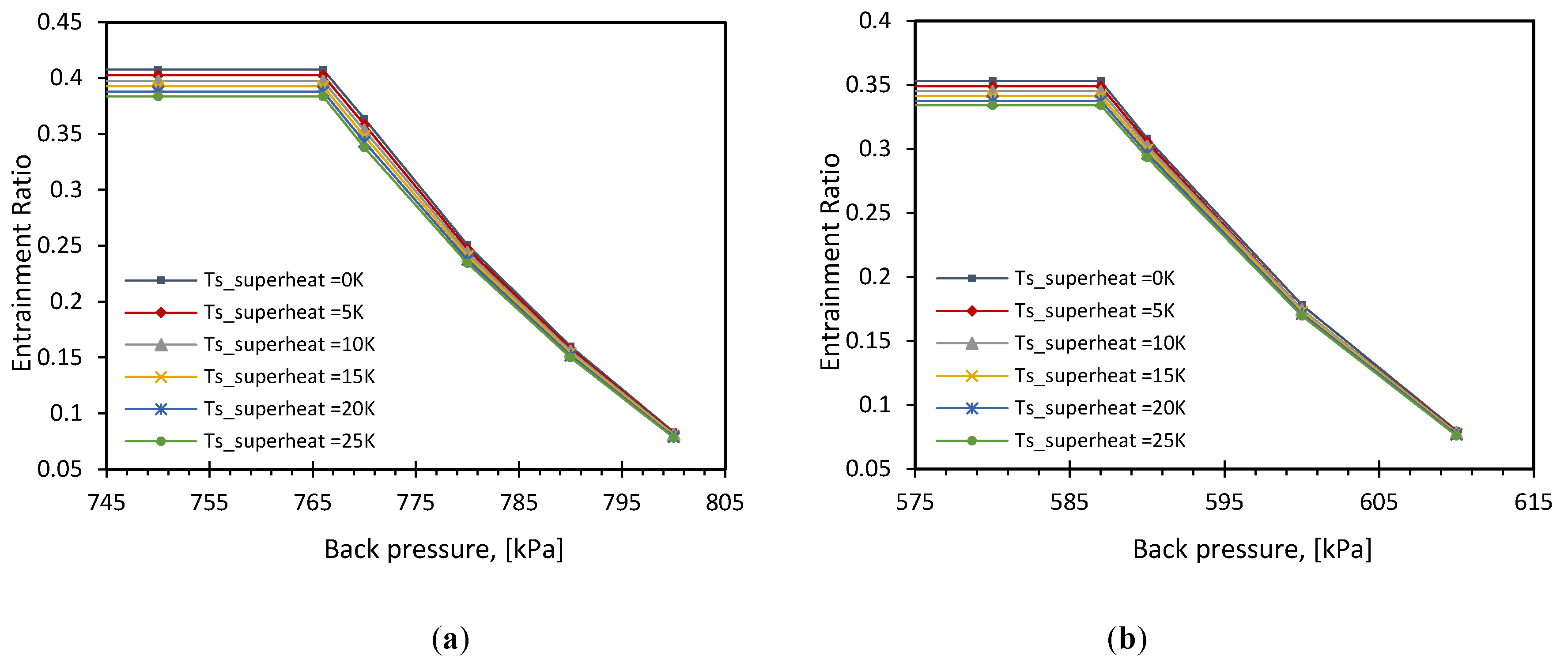
6.2. Effect of Superheat

In general, the main sources of superheat affecting the ejector operation can be divided into two parts. The first part is due to the internal superheat created by flow irreversibility as a result of the existence of normal shock waves and friction during stream mixing. Another source comes from superheating the inlet primary and/or secondary flow. The global superheat effect then will be a combination of these effects depending on the flow characteristics at inlet constant section determined by the Mach number. The input stream with superheat affects the performance of the system differently. Slightly superheating the refrigerant at the inlet may ensure that the formation of droplets inside the ejector is prevented. Formation of droplets is caused by internal condensation after the working fluids in the primary and secondary nozzles are expanded. This should be prevented because it seriously affects the gas dynamic process and the performance of the ejector [16,29]. In addition, blockage of the effective area arises, and this may lead to bumping of the ejector wall which will cause periodically oscillating, unsteady flow, and thus the ejector operation becomes unstable [30,31].
However, the degree of superheat excess will have a negative impact on the system overall performance because of the energy being wasted. The main observations from the results obtained in case of primary flow superheated are shown in Figure 8. The results reveal that, at fixed inlet saturated pressure at Tp = 80 °C and Ts = 6 °C, increasing the degree of superheat in the inlet primary flow will significantly increase the entrainment ratio and thus the ejector performance. For R1234yf, ω increased by 6.31% when the primary flow temperature is superheated with 5 K. Moreover, ω extended 20.70% higher when the degree of superheating reached 25 K, and after which ω is barely improved by the excessive superheat. For example, for the last 5 K added to reach 25 K of superheat, ω increased only by 2.43% compared with 6.31% increasing of ω at the first 5 K of superheat added. R1234ze(E) has the same influence of increasing ω with increasing the degree of superheat in the primary flow but around half the values compared to R1234yf. For example, ω is increased by just 11.48% at 25 K degree of superheat. The condition of increasing superheat coincides with slight travel of critical pressure point towards higher back pressure range.
The previous result of increasing the superheat degrees in the primary flow contrasts with the secondary flow superheating which has negative impact on the performance while maintaining fixed conditions at the primary inlet flow, as illustrated in Figure 9. It can be seen that 5 K of secondary flow superheat decreased ω by 1.30% and 1.16% for R1234yf and R1234ze(E), respectively. Further, ω continued declining by around 1.17% for each 5 K degree of superheat added. This effect is very small compared to the primary flow superheat and explaining why it is negligible in most of the research papers, for example, that of Chen et al. [32].

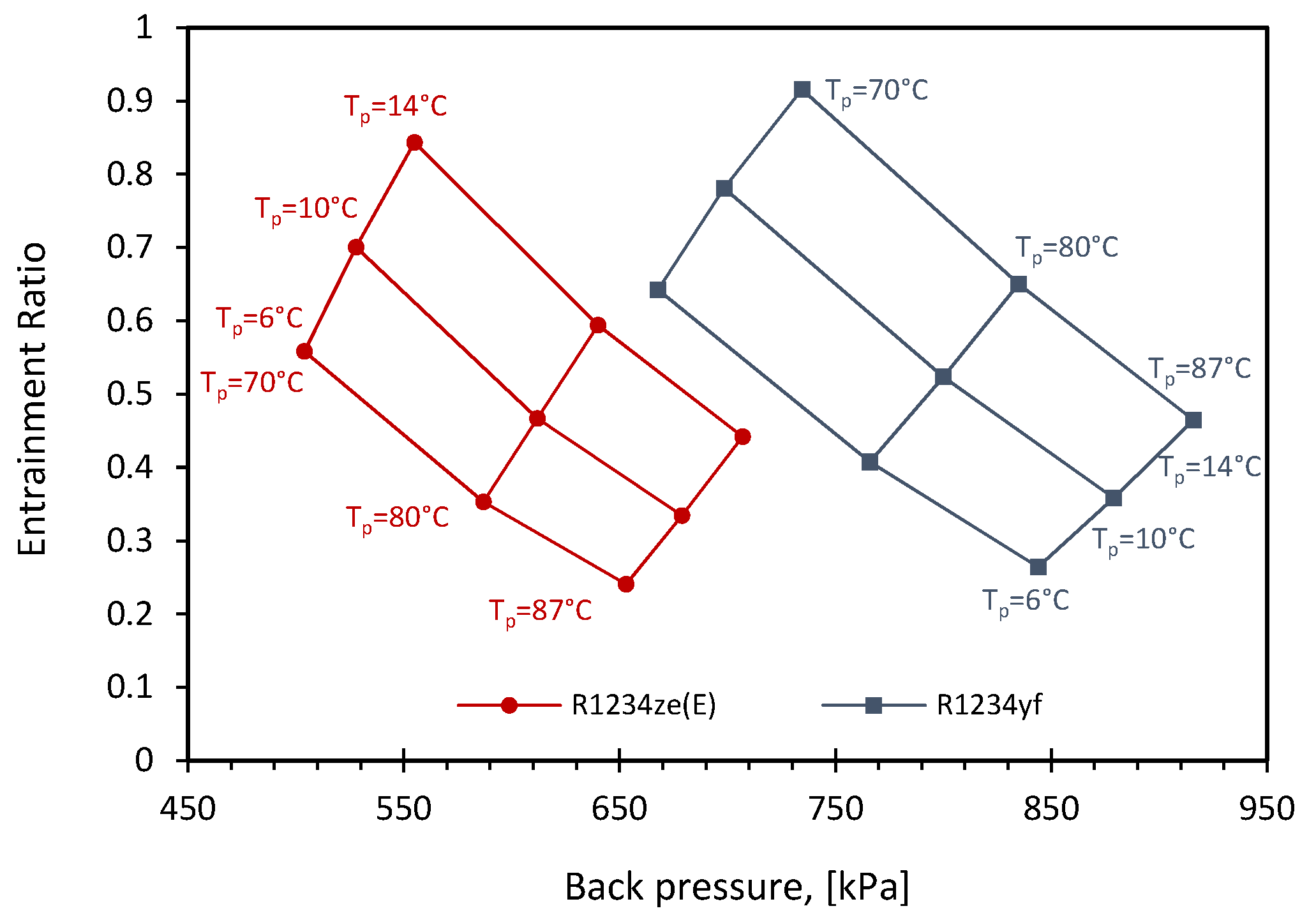
6.3. Ejector Performance Mapping

To limit the number of the numerical simulations required to analyze ejector performance that relies on different inlet and outlet operation conditions, characteristic curves are generally proposed in terms of these variables which can provide a useful and universal aid to the practical design. The analysis yields a critical system design map from which a system design can be simply studied. The map can be plotted for the ejector using data from simulations or experiments including ω and critical back pressure [13,33,34]. A complete performance map expressed by ejector entrainment ratio varying with the critical back pressure for a range of primary and secondary flow temperatures under saturation conditions for both working fluids is reported in Figure 10.

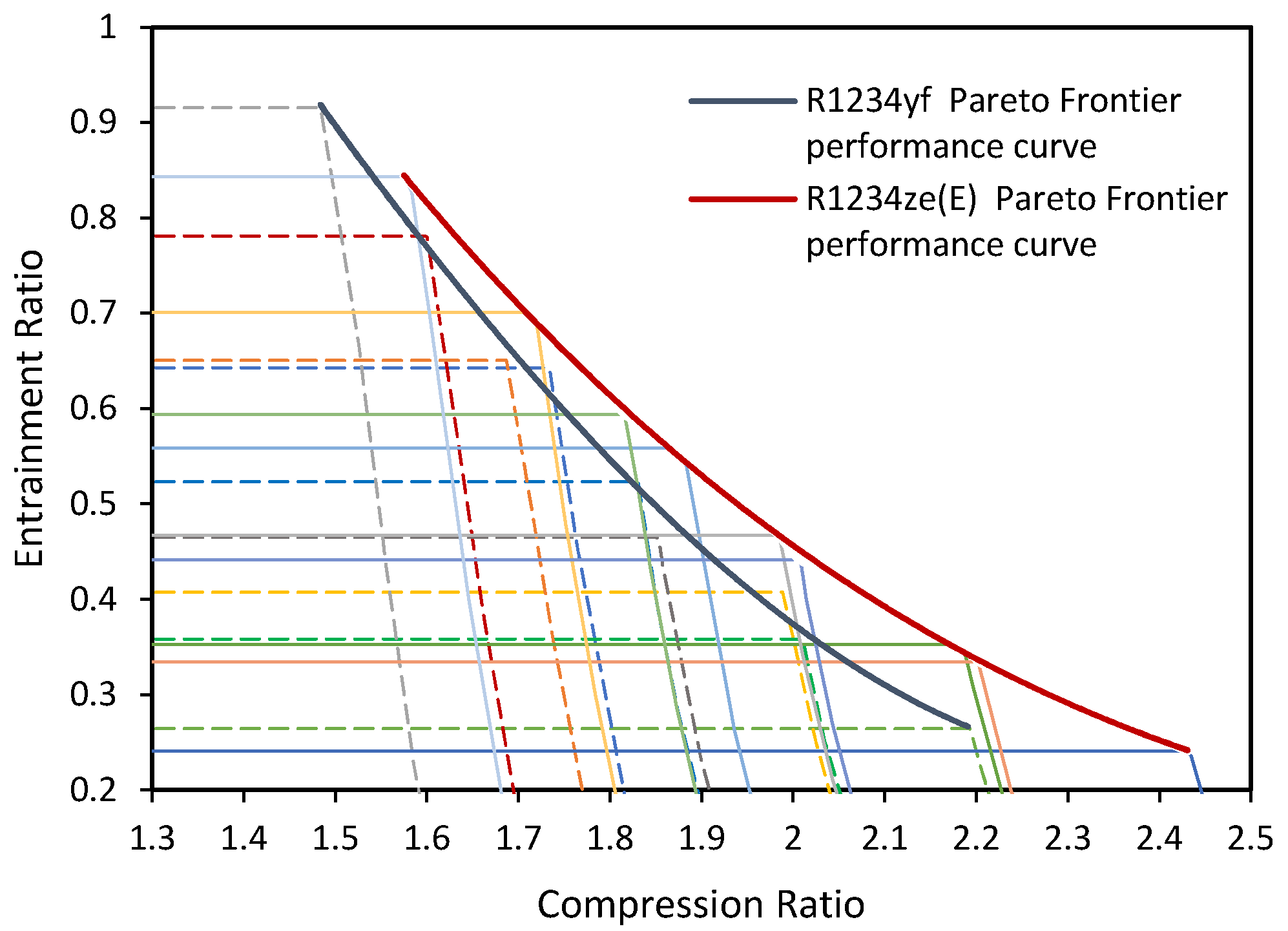
6.4. Pareto Frontier Solution Curve

A Pareto frontier performance curve predicts the critical back pressure at which the critical working mode of the ejector ends [12]. Alternatively, it can demonstrate the boundaries of the baseline’s limit, where the variation of the working design parameters is practical and can be consider as an optimum solution. Figure 11 shows the Pareto frontier performance curve for all operation cases of the ejector based on CFD results drawn on the critical points. It can be seen that R1234ze(E) performs much better, unlike as seen in a previous comparison because of the higher entrainment ratio achieved for a given compression ratio. In this nondimensional comparison, R1234ze(E) is working under higher compression ratio since the secondary flow pressure at the saturation condition is much lower relative to R1234yf. Generally, operating at high condenser temperature (high back pressure) requires high compression ratio to pressurize the mixed stream to the increased condenser pressure and thus causing low entrainment ratio. It can be concluded that by using the Pareto frontier performance curve, the critical entrainment ratio ωcri can be predicted for both refrigerants by the help of their pressure lift ratio in this ejector and specify the working mode using polynomial relations (1) and (2) with ±7.11% and ±2.26% accuracy for R1234yf and R1234ze(E), respectively. Nevertheless, at any equivalent expansion ratio under any operation condition the performance characteristics follow the same trend. For example, for R1234yf at Tp = 80 °C, Ts = 6 °C, ER = 6.54 and Tp = 87 °C, Ts =10 °C, ER = 6.63, the difference in critical value of compression ratio is ±1%. Moreover, R1234ze(E) has ±0.77% difference at Tp = 80 °C, Ts = 6 °C, ER = 7.47, and Tp = 87 °C, Ts = 10 °C, ER = 7.54.
ω c r i _ R 1234 y f = 0.2166 C R 3 0.5345 C R 2 1.1788 C R + 3.1368
ω c r i _   R 1234 z e ( E ) = 0.1121 C R 3 + 1.1586 C R 2 3.9764 C R + 4.6712
The expansion ratio (ER) of both refrigerants has been accomplished in linear relationship using their critical compression ratio within ±0.30% accuracy. These correlations are concluded in Equations (3) and (4). By using these relations, the ejector expansion ratio can be easily achieved with the help of the critical compression ratio and simplified the techniques to calculate the entrainment ratio at any operation condition. This approach could save computational time and cost for predicting the ejector performance.
E R R 1234 y f = 4.7991 C R c r i 3.0028
E R R 1234 z e ( E ) = 4.7757 C R c r i 2.9626

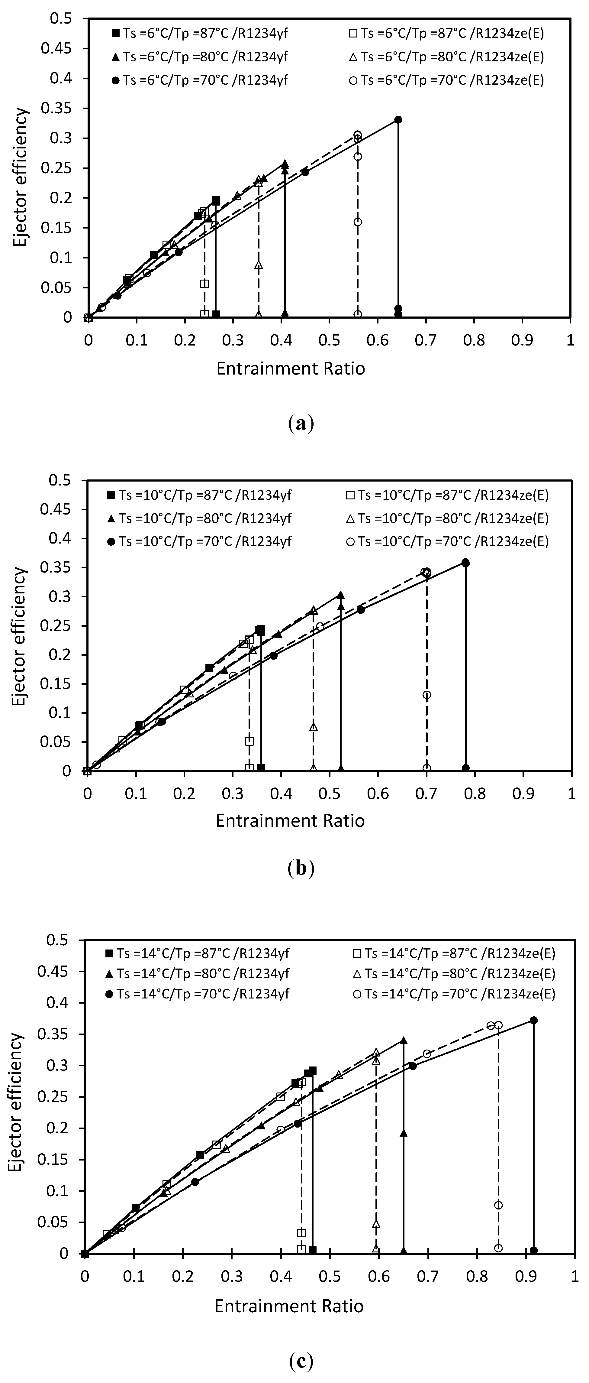
6.5. Ejector Efficiency

The ejector efficiency was first introduced by Köhler et al. [35]. The great advantage of this represented efficiency is that it can be calculated by using only the external parameters which are easy to measure. The same expression for the total ejector efficiency was presented by Elbel et al. deriving by different approach as shown in Equation (5) [36]. This formula was used in many other literatures, as in [37,38,39]. It was defined as the ratio of the amount of the recovered ejector expansion work rate with maximum possible expansion work rate recovery potential. It can also describe the effectiveness of the ejector as the ratio of actual work recovered to the maximum available work recovery.
η e j e c t o r = ω h s , i s h s h p h p , i s
where hs,is and hp,is are referred to specific enthalpy for an assumed isentropic state from the inlet primary and secondary conditions to the ejector outlet pressure. hs and hp are the specific enthalpy for the inlet primary and secondary conditions.
Moreover, Dvorak et al. proposed the ejector efficiency based on the relation between the specific compression work acquired by the secondary stream and the specific work exerted by the primary flow as Equation (6) [40]. This formula has been used in many researches [41,42]. The only problem in Dvorak formula is the adiabatic exponent which needs to be constant and represents the ideal gas flow. Therefore, Equation (5) is used in this work to analyze the efficiency for the ejector model.
η e j e c t o r = ω 1 ( P s / P c ) k 1 / k ( P p / P c ) k 1 / k 1
In Figure 12 the ejector efficiency based on the numerical results were presented for different working conditions. The markers on the figure show the CFD obtained results while as the lines predict the efficiency that fit these results. The same trends were revealed for both refrigerants’ efficiencies. In addition, the characteristic curve of the ejector efficiency ends at which the critical flow occurs. A further reduction in the back pressure at critical mode will not lead to an increase in the entrainment ratio through the ejector and will only decline the efficiency until zero. It can be seen that R1234ze(E) has higher efficiency compared to R1234yf under the same entrainment ratio while R1234yf could provide higher ejector efficiency at critical point. The maximum efficiency reached at the critical point were 0.372 and 0.364 for R1234yf and R1234ze(E) respectively. Furthermore, at fixed Ts, the ejector has high efficiency when it works under low Tp. On the other hand, at subcritical mode condition where the back pressure increases, the efficiency decreases which is as a result of the decreasing of the mass entrainment ratio at these operation conditions. Comparing the results in the case of using Dvorak’s proposal as an ideal efficiency of the gas flow, the efficiency of the ejector will have the same change trends, with lower values up to 16% in the case of R1234yf and 5.36% for R1234ze(E).

7. Conclusions

This paper is mainly devoted to computational fluid dynamics simulation conducted for a 2D axisymmetric ejector to present the performance over the entire operation conditions using NIST real gas model integrated in commercial ANSYS Fluent. The experimental data were used to validate how effective the model is. The comparison results have shown that the model could accurately be able to predict the experimental results with error less than ±14%. The numerical analysis study was applied using k-ω SST turbulence model and pressure-based coupled solver. Most of the simulations converged to the residues fall below 1×10⁻⁸. HFOs (R1234ze(E) and R1234yf) were selected as the working fluids because of their promising alternatives to fluorocarbons with low global warming potential and flammability as well as adhering to EU Council regulations. Mesh sensitivity was performed to ensure the result stability via different number of elements.
The inlet primary and the secondary flow were examined under their saturation conditions. Given the energy available in the primary flow, the ejector performance is assessed based on how much of this energy the secondary flow can recover. This was done by investigating the characteristic curves for the ejector critical and subcritical modes. It was shown that increasing the primary flow temperature caused lower entrainment ratio and produced higher critical back pressure. When the primary or secondary saturated flow temperatures are fixed then the compression ratio will increase with increasing the expansion ratio and causes lower entrainment ratio indeed. As a result, R1234yf represented higher entrainment ratio than R1234ze(E) by 4.91% to 15.60%. The contours of Mach number for both working fluids at different inlet primary pressure and different back pressure were represented. Several phenomena in the ejector were discussed, like the shock waves, effective mixing, and operational modes. In order to prevent the formation of droplet inside the ejector, adding degree of superheat in the inlet flow is important but the excess of value will have a negative impact on the system overall performance because of the energy being wasted. Therefore, the amount of superheat to be added should be carefully studied. From the performance evaluation point of view, the analysis demonstrated that the entrainment ratio can be increased up to 20.70% with 25 K superheat for R1234yf, which is almost double the percentage compared to R1234ze(E). Secondary flow superheating has a negative impact on the performance, which slightly decreases ω within 1.17% for both refrigerants for each 5 K degree of superheat added.
Ejector performance map was proposed using the critical back pressure to obtain the characteristic curve and show the large critical mode which R1234yf can work in comparing to R1234ze(E). A Pareto frontier performance curve was performed. This approach could save computational time and cost for predicting the ejector performance by calculating the critical entrainment ratio using ejector pressure lift ratio. Moreover, the expansion ratio (ER) of both refrigerants was accomplished in linear correlation using their critical compression ratio. It was also shown that regardless of any operation condition, the refrigerant working at equivalent expansion ratio have similar performance characteristics curve trend. The effectiveness of the modelled ejector was determined to compare both working fluids efficiency. The maximum efficiency reached at the critical point was 0.372 and 0.364 for R1234yf and R1234ze(E) respectively. In other words, the efficiency was lower when using ideal gas flow formula. The ideal gas model has been simulated and compared with the real gas model. It was concluded that the performance of the ejector will be overestimated in the case of using the ideal gas model with maxima of 50.26% and 25.66% for R1234yf and R1234ze(E), respectively. This explains the necessity of using a real gas model in CFD and why the ideal gas model could fail to predict the performance of the ejector. In a nutshell, R1234ze(E) can achieve relatively better overall performance than R1234yf.
This study was conducted to design a high-performance ejector that has been manufactured already and currently under test. The main essential parameters for energy-efficient HFOs ejector cooling systems have been investigated to estimate the suitability of the modeled ejector. However, more results and greater accuracy, for example, the effect of the NXP, pressure distribution along the ejector, and the entropy generation will be considered and validated with experiments in future work.

Author Contributions

Conceptualization, A.F.A.E. and V.V.N.; Data curation, A.F.A.E. and V.D.; Formal analysis, A.F.A.E.; Funding acquisition, A.F.A.E., V.V.N. and V.D.; Investigation, A.F.A.E. and S.M.; Methodology, A.F.A.E. and V.D.; Project administration, V.V.N.; Resources, A.F.A.E.; Software, A.F.A.E. and S.M.; Supervision, V.D.; Validation, A.F.A.E. and S.M.; Writing—original draft, A.F.A.E.; Writing—review & editing, A.F.A.E., V.D. and S.M. All authors have read and agreed to the published version of the manuscript.

Funding

This publication was written at the Technical University of Liberec as part of the project 21226/2220 with the support of the Specific University Research Grant, as provided by the Ministry of Education, Youth and Sports of the Czech Republic in the year 2019.

Conflicts of Interest

The authors declare no conflict of interest.

Nomenclature

CRcompression ratio parameter
ERexpansion ratio
NXPNozzle Exit Position
hspecific enthalpy (kJkg−1)
PPressure (kPa)
TTemperature (°C)
ω entrainment ratio (-)
η efficiency (-)
mass flow rate (kg/s)
κspecific heat ratio, (-)
Subscripts
pprimary flow
ssecondary flow
coutlet mixed flow
cricritical
isisentropic

References

  1. Shestopalov, K.O.; Huang, B.J.; Petrenko, V.O.; Volovyk, O.S. Investigation of an experimental ejector refrigeration machine operating with refrigerant R245fa at design and off-design working conditions. Part 1. Theoretical analysis. Int. J. Refrig. 2015, 55, 201–211. [Google Scholar] [CrossRef]
  2. International Energy Agency. Air Conditioning Use Emerges as One of the Key Drivers of Global Electricity-Demand Growth. Available online: https://www.iea.org/newsroom/news/2018/may/air-conditioning-use-emerges-as-one-of-the-key-drivers-of-global-electricity-dema.html (accessed on 15 October 2019).
  3. Honra, J.; Berana, M.S.; Danao, L.A.M.; Manuel, M.C.E. CFD analysis of supersonic ejector in ejector refrigeration system for air conditioning application. Lect. Notes Eng. Comput. Sci. 2017, 2230, 1019–1024. [Google Scholar]
  4. Chen, X.; Omer, S.; Worall, M.; Riffat, S. Recent developments in ejector refrigeration technologies. Renew Sustain Energy Rev. 2013, 19, 629–651. [Google Scholar] [CrossRef]
  5. Besagni, G.; Inzoli, F. Computational fluid-dynamics modeling of supersonic ejectors: Screening of turbulence modeling approaches. Appl. Therm. Eng. 2017, 117, 122–144. [Google Scholar] [CrossRef]
  6. He, S.; Li, Y.; Wang, R.Z. Progress of mathematical modeling on ejectors. Renew Sustain Energy Rev. 2009, 13, 1760–1780. [Google Scholar] [CrossRef]
  7. Scott, D.; Aidoun, Z.; Bellache, O.; Ouzzane, M. CFD Simulations of a Supersonic Ejector for Use in Refrigeration Applications. Refrig. Air Cond. 2008, 2159, 1–8. [Google Scholar]
  8. ANSYS Fluent Release 15 User’s Guide. Available online: http://www.pmt.usp.br/academic/martoran/notasmodelosgrad/ANSYS Fluent Users Guide.pdf (accessed on 15 October 2019).
  9. Cai, L.; He, M. A numerical study on the supersonic steam ejector use in steam turbine system. Math Probl. Eng. 2013, 2013, 1–10. [Google Scholar] [CrossRef]
  10. Chen, W.; Shi, C.; Zhang, S.; Chen, H.; Chong, D.; Yan, J. Theoretical analysis of ejector refrigeration system performance under overall modes. Appl. Energy. 2017, 185, 2074–2084. [Google Scholar] [CrossRef]
  11. The European Parliament and the Council of the European Union. REGULATION (EU) No 517/2014. Off. J. Eur. Union. 2014, 57, 195–230. [Google Scholar]
  12. Mohamed, S.; Shatilla, Y.; Zhang, T.J. CFD-based design and simulation of hydrocarbon ejector for cooling. Energy 2019, 167, 346–358. [Google Scholar] [CrossRef]
  13. Chunnanond, K.; Aphornratana, S. Ejectors: Applications in refrigeration technology. Renew Sustain Energy Rev. 2004, 8, 129–155. [Google Scholar] [CrossRef]
  14. Besagni, G.; Mereu, R.; Inzoli, F. Ejector refrigeration: A comprehensive review. Renew Sustain Energy Rev. 2016, 53, 373–407. [Google Scholar] [CrossRef] [Green Version]
  15. Little, A.B.; Garimella, S. A Review of Ejector Technology for Refrigeration Applications. Int. J. Air-Cond. Refrig. 2011, 19, 1–15. [Google Scholar] [CrossRef]
  16. Huang, B.J.; Chang, J.M.; Wang, C.P.; Petrenko, V.A. 1-D analysis of ejector performance. Int. J. Refrig. 1999, 22, 354–364. [Google Scholar] [CrossRef]
  17. Zhang, T.; Mohamed, S. Conceptual Design and Analysis of Hydrocarbon-Based Solar Thermal Power and Ejector Cooling Systems in Hot Climates. J. Sol. Energy Eng. 2014, 137, 021001. [Google Scholar] [CrossRef]
  18. Grazzini, G.; Milazzo, A.; Mazzelli, F. Ejectors for Efficient Refrigeration: Design, Applications and Computational Fluid Dynamics. Available online: https://link.springer.com/book/10.1007/978-3-319-75244-0 (accessed on 15 October 2019).
  19. Pianthong, K.; Seehanam, W.; Behnia, M.; Sriveerakul, T.; Aphornratana, S. Investigation and improvement of ejector refrigeration system using computational fluid dynamics technique. Energy Convers. Manag. 2007, 48, 2556–2564. [Google Scholar] [CrossRef]
  20. Lemmon Eric, W.; Bell Marcia, L.H.; Mark, O.M. REFPROP Documentation Release 10. Reference Fluid Thermodynamic and Transport Properties. Available online: https://data.nist.gov/od/id/ECBCC1C130222ED9E04306570681B10740 (accessed on 15 October 2019).
  21. Bartosiewicz, Y.; Aidoun, Z.; Desevaux, P.; Mercadier, Y. Numerical and experimental investigations on supersonic ejectors. Int. J. Heat Fluid Flow. 2005, 26, 56–70. [Google Scholar] [CrossRef]
  22. Besagni, G.; Mereu, R.; Chiesa, P.; Inzoli, F. An Integrated Lumped Parameter-CFD approach for off-design ejector performance evaluation. Energy Convers. Manag. 2015, 105, 697–715. [Google Scholar] [CrossRef]
  23. Kracik, J.; Dvorak, V.; Nguyen Van, V.; Smierciew, K. Experimental and Numerical Study on Supersonic Ejectors Working with R-1234ze(E). EPJ Web. Conf. 2018, 180, 02047. [Google Scholar] [CrossRef]
  24. Croquer, S.; Poncet, S.; Aidoun, Z. Turbulence modeling of a single-phase R134a supersonic ejector. Part 1: Numerical benchmark Modélisation de la turbulence d ’ un éjecteur supersonique au R134a monophasé. Partie 1: Référence numérique. Int. J. Refrig. 2016, 61, 140–152. [Google Scholar] [CrossRef]
  25. Zheng, P.; Li, B.; Qin, J. CFD simulation of two-phase ejector performance influenced by different operation conditions. Energy 2018, 155, 1129–1145. [Google Scholar] [CrossRef]
  26. Hart, J.H. Supersonic Ejector Simulation and Optimisation. Ph.D. Thesis, Department of Mechanical Engineering, Sheffield University, Sheffield, UK, 2002. [Google Scholar]
  27. Ali, A. A Theoretical and Experimental Investigation of Jet- Pump Refrigeration System. Ph.D. Thesis, University of Nottingham, Nottingham, UK, May 2006. [Google Scholar]
  28. Hanafi, A.S.; Mostafa, G.M.; Waheed, A.; Fathy, A. 1-D Mathematical Modeling and CFD Investigation on Supersonic Steam Ejector in MED-TVC. Energy Procedia. 2015, 75, 3239–3252. [Google Scholar] [CrossRef] [Green Version]
  29. Aidoun, Z.; Ouzzane, M. The effect of operating conditions on the performance of a supersonic ejector for refrigeration. Int. J. Refrig. 2004, 27, 974–984. [Google Scholar] [CrossRef]
  30. Chen, J.; Havtun, H.; Palm, B. Screening of working fluids for the ejector refrigeration system. Int. J. Refrig. 2014, 47, 1–14. [Google Scholar] [CrossRef]
  31. Grazzini, G.; Milazzo, A.; Piazzini, S. Prediction of condensation in steam ejector for a refrigeration system. Int. J. Refrig. 2011, 34, 1641–1648. [Google Scholar] [CrossRef]
  32. Chen, J.; Havtun, H.; Palm, B. Parametric analysis of ejector working characteristics in the refrigeration system. Appl. Therm. Eng. 2014, 69, 130–142. [Google Scholar] [CrossRef]
  33. Huang, B.J.; Jiang, C.B.; Hu, F.L. Ejector performance characteristics and design analysis of jet refrigeration system. J. Eng. Gas Turbines Power. 1985, 107, 792–802. [Google Scholar] [CrossRef]
  34. Eames, I.W.; Ablwaifa, A.E.; Petrenko, V. Results of an experimental study of an advanced jet-pump refrigerator operating with R245fa. Appl. Therm. Eng. 2007, 27, 2833–2840. [Google Scholar] [CrossRef]
  35. Köhler, J.; Richter, C.; Tegethoff, W.; Tischendorf, C. Experimental and Theoretical Study of a CO2 Ejector Refrigeration Cycle. In Proceedings of the VDA Winter Meeting, Saalfelden, Austria, 14–15 February 2007. [Google Scholar]
  36. Elbel, S.; Hrnjak, P. Experimental validation of a prototype ejector designed to reduce throttling losses encountered in transcritical R744 system operation. Int. J. Refrig. 2008, 31, 411–422. [Google Scholar] [CrossRef]
  37. Haida, M.; Smolka, J.; Hafner, A. Performance mapping of the R744 ejectors for refrigeration and air conditioning supermarket application: A hybrid reduced-order model. Energy 2018, 153, 933–948. [Google Scholar] [CrossRef]
  38. Lucas, C.; Koehler, J. Experimental investigation of the COP improvement of a refrigeration cycle by use of an ejector. Int. J. Refrig. 2012, 35, 1595–1603. [Google Scholar] [CrossRef]
  39. Zheng, L.; Deng, J. Research on CO2 ejector component efficiencies by experiment measurement and distributed-parameter modeling. Energy Convers. Manag. 2017, 142, 244–256. [Google Scholar] [CrossRef]
  40. Václav, D.; Tomáš, V. Experimental and Numerical Study of Constant Area Mixing. Available online: fluids.fs.cvut.cz/akce/konference/istp_2005/full/160.pdf (accessed on 15 October 2019).
  41. Butrymowicz, D.; Śmierciew, K.; Karwacki, J.; Gagan, J. Experimental investigations of low-temperature driven ejection refrigeration cycle operating with isobutane. Int. J. Refrig. 2014, 39, 196–209. [Google Scholar] [CrossRef]
  42. Liu, F. Review on Ejector Efficiencies in Various Ejector Systems. 15th Int. Refrig. Air Cond Conf. 2014, 1533, 1–10. [Google Scholar]
Figure 1. Schematic diagram of the ejector geometries as the base model.
Energies 13 01408 g001
Figure 2. Mesh of the flow region.
Energies 13 01408 g002
Figure 3. CFD model validation with experimental result Ref. [16] and comparing result from Ref. [12].
Energies 13 01408 g003
Figure 4. Ejector CFD results with real and ideal gas model vs entrainment ratio at Ts =6 °C. (a) R1234yf. (b) R1234ze(E).
Energies 13 01408 g004
Figure 5. CFD Entrainment ratio vs back pressure for the ejector at different primary and secondary flow temperatures when (a) Tp = 70 °C. (b) Ts = 6 °C. (c) Tp = 80 °C. (d) Ts = 10 °C. (e) Tp = 87 °C. (f) Ts = 14 °C.
Energies 13 01408 g005aEnergies 13 01408 g005b
Figure 6. Mach number contours inside ejector baseline given Tp = 70, 80, 87 °C respectively from top to bottom for (a) R1234ze(E) at Ts = 10 °C, Pc = 560 kPa. (b) R1234yf at Ts = 10 °C, Pc = 730 kPa.
Energies 13 01408 g006aEnergies 13 01408 g006b
Figure 7. Mach number contours with different back pressure inside ejector baseline given Tp = 80 °C, Ts = 10 °C for: (a) R1234ze(E) at Pc = 600, 613, 645 kPa respectively from top to bottom. (b) R1234yf at Pc = 780, 801, 840 kPa, respectively from top to bottom.
Energies 13 01408 g007aEnergies 13 01408 g007b
Figure 8. CFD Entrainment ratio vs back pressure for the ejector with superheated primary flow at Ts = 6 °C and Tp = 80 °C (a) R1234yf. (b) R1234ze(E).
Energies 13 01408 g008
Figure 9. CFD Entrainment ratio vs back pressure for the ejector with superheated secondary flow at Ts = 6 °C and Tp = 80 °C (a) R1234yf. (b) R1234ze(E).
Energies 13 01408 g009
Figure 10. Performance map of the ejector based on CFD data.
Energies 13 01408 g010
Figure 11. Pareto Frontier performance curve for all operation cases of the ejector based on CFD data.
Energies 13 01408 g011
Figure 12. Ejector efficiency vs the mass entrainment ratio for various working conditions based on CFD results. (a) Ts = 6 °C. (b) Ts =10 °C. (c) Ts = 14 °C.
Energies 13 01408 g012
Table 1. Mesh sensitivity results.
Working FluidCaseMesh [Cells]s [kg/s]p [kg/s]ω [-]Tc [K]
R1234ze(E)1270,1820.05160.09240.5585308.9
R1234ze(E)21,074,1460.05180.09190.5639308.8
R1234ze(E)34,196,3300.05190.09170.5665308.9
R1234yf1274,2410.07910.12300.6427298.6
R1234yf21,076,7950.07940.12240.6489298.5
R1234yf34,198,4630.07960.12240.6500298.5
Primary flow Temperature 70 °C, secondary flow Temperature 6 °C. Degree of superheat 0K, outlet pressure 400 kPa.
Table 2. Verification of the CFD results with Huang et al. experimental results.
Huang et al. 1999 (Experimental) [16]Present Work (Numerical)
EjectorPp
[kPa]
Ps
[kPa]
Pc
[kPa]
ω
[-]
ω
[-]
Error
%
p
[kg/s]
s
[kg/s]
Tc
[°C]
Cells
No.
AA538.2039.97128.130.22460.23936.560.011940.00286340.35211,900
AA465.6839.97114.220.28800.2685−6.790.010380.00279335.04211,900
AA604.7947.26144.260.23500.25649.100.013360.00343343.76211,900
AA604.7939.97142.390.18590.18962.020.013360.00253346.14211,900
AA538.2047.26130.720.29460.2943−0.110.011940.00351338.88211,900
AA465.6847.26116.190.33980.35775.270.010380.00371332.74211,900
AG604.7947.26127.280.35030.3175−9.370.0133450.00424340.83210,100
AG538.2047.26116.190.40340.3769−6.560.0119210.00449335.54210,100
AG465.6847.26102.590.47900.49383.080.0103660.00512328.35210,100
AG400.7447.2691.590.61320.6059−1.180.0089680.00543322.19210,100
AC604.7939.97117.380.28140.2671−5.090.0133620.00357341.92237,600
AC538.2039.97107.720.34880.3005−13.850.0119360.00359337.23237,600
AC465.6839.9795.940.42410.3872−8.710.0103790.00402330.27237,600
AC400.7439.9784.2620.48890.53048.480.008980.00476322.50237,600
AD604.7939.97106.980.34570.3056−11.600.0133560.00408339.96235,200
AD465.6839.9787.700.53870.4770−11.450.0103750.00495327.24235,200
AD400.7439.9776.8340.62270.65675.450.0089750.00589319.27235,200
AD604.7947.26110.360.45410.4276−5.850.0133560.00571336.43235,200
AD538.2047.26101.160.54220.5198−4.130.0119310.0062330.727235,200
AD465.6847.2690.600.63500.66244.310.0103750.00687323.88235,200
AD400.7447.2680.6290.74120.823111.050.0089750.00739317.66235,200
EG604.7939.97137.360.20430.225110.180.0153410.00345344.27196,860
EC604.7939.97177.700.22730.250810.350.0153390.00385342.85195,829
EC604.7947.26129.850.30400.2976−2.120.0153390.00456341.64195,829
ED604.7939.97120.610.29020.2512−13.450.0152290.00383342.63240,400
EE604.7939.97109.230.35050.35802.150.0152290.00545337.89236,800
EE604.7947.26109.230.40480.447710.590.0152290.00682335.65236,800
EF604.7939.97104.770.39370.3635−7.680.0151480.00551337.55233,600
EF604.7947.26105.130.49890.50441.110.0151480.00764333.76233,600
EH604.7939.9798.700.43770.4272−2.400.0152630.00652335.03242,300

