Abstract
Aero-fuel centrifugal pumps are important power plants in aero-engines. Unlike most of the existing centrifugal pumps, a combination impeller is integrated with the pump to improve performance. First, the critical geometrical parameters of the combination impeller and volute are given. Then, the effects of the combination impeller on the flow characteristics of the impeller and volute are clarified by comparing simulation results with that of the conventional impeller, where the effectiveness of the selected numerical method is validated by an acceptable agreement between simulation and experiment. Finally, the experiment is set to test the external performance of the studied pump. A significant feature of this study is that the flow characteristics are significantly ameliorated by reducing the flow losses that emerged in the impeller inlet, impeller outlet, and volute tongue. Correspondingly, the head and efficiency of a combination impeller are higher with comparison to a conventional impeller. Consequently, it is a promising approach in ameliorating the flow field and improving external performance by applying a combination impeller to an aero-fuel centrifugal pump.
1. Introduction
As an energy consuming turbo-machine, the centrifugal pump is of urgent demand for energy source in the industry due to its energy-saving potential. It has been widely used for many applications, such as aviation and aerospace [1,2], micro-hydro-power plants [3,4], wind power generation [5,6], petroleum process [7], and agriculture irrigation [8]. Importantly, there is a growing recognition in the field of improving the performance of a centrifugal pump for a military aero-engine [9]. The centrifugal pumps are usually used as the pre-pressurization pumps for fuel systems of aero-engines. The impeller structure plays a critical role in utilizing the energy for improving the pump performance, where the fuel is pumped to take the energy from inlet to the volute in form of kinetic energy and static pressure. Therefore, the critical issues regarding the performance of an aero-fuel centrifugal pump with the proposed combination impeller need to be specially considered, which are normally beyond what a conventional method can provide.
As for the vital role of an impeller for a centrifugal pump, many investigations on impeller design and performance prediction have been carried out. In [10], two phase performances for different centrifugal pumps are studied, and the experiment and simulation results are close. It is still useful to perform experimental two-phase flow studies. In [11], the Back Propagation (BP) neural network technique is used to predict centrifugal pump performance. It indicates that the BP neural network can realize hydraulic performance prediction to help engineers design centrifugal pumps. In [12], an additional splitter blade is presented and integrated in a centrifugal pump. It shows that a higher performance is obtained than that of the pump with a conventional impeller. Moreover, the effect of the geometrical parameters of the impeller on performance has been conducted. In [13], the efficiency can be changed effectively by slightly changing the axial clearance of the impeller. In [14], the performance of the head and cavitation for centrifugal pumps are affected by the blade angle. In addition, an optimum value of hydraulic efficiency can be obtained when adjusting the impeller shroud radius [15]. Therefore, it is important to analyze the performance for an aero-fuel centrifugal pump with different impellers under various operation conditions. As one of the motivations in this paper, the effect of the proposed combination impeller on external performance is investigated to ensure its superiority.
Furthermore, numerical simulation has been investigated to realize the effects of an impeller on fluid characteristics in centrifugal pumps. In [16], by using Computational Fluid Dynamics (CFD) commercial software, it shows that the pump efficiency is highly affected by the number of blades. Additionally, different turbulence models are selected to simulate the flow fields with different numbers of blades. In [17], in order to predict the external performance of the pump, 3-D flow fields inside the pump are simulated by adjusting the blade outlet width and impeller outlet angle. With comparisons between simulation and experiment results, the validation study is proved. For the complex flow characteristics occurring in the impeller, it usually has an adverse effect on cavitation performance [18,19]. In [18], the cavitation can be induced due to the serious hydraulic shock acting on the blade under some extreme conditions. The impeller geometrical parameters are important factors to improve the performance of anti-cavitation for a centrifugal pump. As indicated in [19], the effect of the inlet blade angle is obvious and sensitive to anti-cavitation performance. In general, there may cause a certain secondary loss, friction loss, or mixing loss inside the impeller. So, a particular impeller can improve the reliability of pump operation by reducing the flow losses. From this review, it is very important for a centrifugal pump to understand its flow characteristics. This presents another motivation for this paper, which aims to realize the effects of a combination impeller on detailed flow characteristics by an effective numerical simulation method, while comparing with experimental data.
Although extensive studies have focused on the effect of an impeller on the flow field and external performance, there are some difficulties that need to be addressed. (1) The flow field and external performance are mainly regulated by the impeller, and the geometrical parameters are treated as the vital factors. So, the effect of an impeller still needs to be investigate [20,21,22,23]. (2) In order to improve hydraulic efficiency and maintain system stability, one can equip an inducer before the impeller, which is a common and conventional method to solve serious flow problems [24,25]. Only a few of them apply a combination impeller on a centrifugal pump. (3) The combination impeller has not been specifically used for an aero-fuel centrifugal pump, and it has not considered the viscosity of aero-fuel [26], the operation conditions under high-pressure, or the large flow rate [27].
In an attempt to overcome the above-mentioned difficulties, this paper presents an aero-fuel centrifugal pump equipped with a combination impeller. The aim is to obtain the detailed flow characteristics and optimal external performances by numerical simulation and experiment. It will be beneficial to have aero-fuel centrifugal pumps with the capability of suppressing serious flow instabilities under extreme conditions by equipping a combination impeller.
2. Research Model Description
2.1. Objective
The aero-fuel centrifugal pump studied is often operating under a large flow rate condition. Its special impeller is a single stage. The pump is used as the pre-pressurization pump in the fuel system of an aero-engine for transporting fuel (RP-3) [1,9]. Aero-fuel (RP-3) is selected as the initial intended working fluid for the simulation and experiment to keep the results precise and approved. The main technical requirements of the studied pump under nominal operating condition are illustrated in Table 1.

Table 1.
The technical requirements under nominal operating condition.
The operating range of the pump is determined by the flight-envelope of the aero-engine, including: rotor speed, flow rate, and inlet and outlet pressure. As shown in Table 1, a shaft speed Nd of 8000 RPM, a flow rate Qd of 77,000 L/h, and a specific speed ns of 106.6 are set as the nominal operating conditions. Meanwhile, the head H is 137 m and the efficiency ηv is 0.65. The pump needs to be capable of pumping fuel at the outlet pressure Pc of 0.956 MPa. The density of the aero-fuel (RP-3) is 779 kg/m3 when operating at 20 °C.
2.2. Configuration and Layout of the Research Model
Figure 1 shows the final pump configuration. It essentially consists of a combination impeller, a volute, a diffuser, and a pump drive shaft. The combination impeller is placed in the middle of the pump. The fuel is transported and accelerated by the impeller in the counterclockwise circumferential direction. Then, around the outlet line of impeller, the fuel is pumped out to the volute by dint of centrifugal force. Finally, the fuel is decelerated in the following diffuser before entering the main-fuel pump of fuel system.
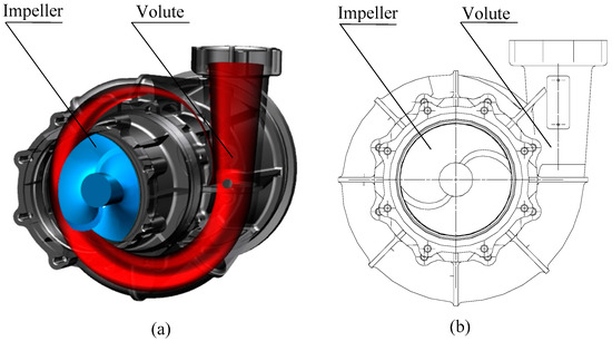
Figure 1.
Final pump configuration: (a) the overall layout; (b) the overall top view.
Figure 2 illustrates the shapes of combination and conventional impellers. It can be seen that the blade profiles of two impellers are similar. Compared to the conventional centrifugal pump, which is shown in Figure 2b, the studied pump in this paper is equipped with a complex impeller. In Figure 2a, it is an integrated and diversion structure, combining a prior inducer and a conventional impeller to optimize the capacity of pressurization and anti-cavitation. The studied impeller is composed of 2 main blades, 2 long-auxiliary blades, and 4 short-auxiliary blades. Besides, the main blade of the combination impeller is combining an inducer blade and a long-auxiliary blade at the combination points, as shown in Figure 2a. So, with comparisons to the conventional impeller, there is a possibility to achieve a better performance by using the combination impeller. Additionally, Figure 2c demonstrates the main geometrical parameters, where the values are illustrated in Table 2.
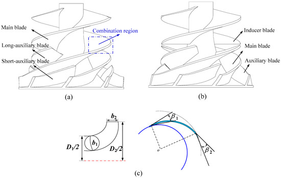
Figure 2.
Shapes of combination and conventional impellers: (a) a combination impeller; (b) a conventional impeller; (c) the main geometrical parameters.
Table 2.
The main geometrical parameters.
In this paper, the volutes of two pumps are the same. The cross-section of volute is a circular shape, and its diameter is alternative at different radian along the base circle. Figure 3 illustrates the geometric drawing process of the volute.
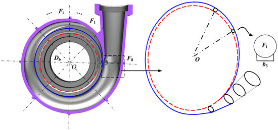
Figure 3.
Geometric drawing process of volute.
The geometrical parameters of the pump are determined Table 1, while the values are presented in Table 2. The inlet and outlet impeller diameters are denoted by D1 and D2, b1 and b2 represent the inlet and outlet blade widths, and the leading and trailing edge angles are expressed by β1 and β2. Additionally, Db is the diameter of the base circle, b3 is the inlet width of the volute, and F8 represents the eighth section area of the volute.
2.3. 3-D Model
The 3-D models of two impellers are established with a basic B-spline modeling method by commercial software, i.e., UG. Figure 4 shows the 3-D models of a combination impeller, a conventional impeller, and a volute.
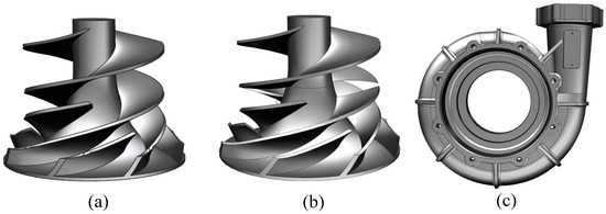
Figure 4.
3-D models: (a) a combination impeller; (b) a conventional impeller; (c) and a volute.
3. Validation Study
In this section, in order to further validate the applicability of the CFD methodology in this paper, a validation study is given to ensure the reliability of results. The numerical simulations for the studied pump are conducted with the set grid-schemes, in order to confirm the independence of the determined mesh grid. Then, the experiment setup is given. Finally, comparing the results between simulation and experiment, the effectiveness of selected turbulence model is conducted.
3.1. Mesh Model
The impeller and volute are the computational domains, where they are generated by means of commercial software, i.e., PUMPLINX (3.4.3, USA Simerics Compony, USA). This software is a Computational Fluid Dynamics (CFD) tool. It provides accurate flow information for designing a pump and predicting its performance. By using PUMPLINX, pump engineers can make more accurate numerical predictions under multiple operating conditions for pump design in less time. Many users have compared the calculation results with the experiments. It is illustrated that the calculation results are relatively close with experiments.
In order to ensure simulation stability and precision, unstructured mesh with good adaptability has been used to divide the computational domain. Figure 5 presents details of the generated mesh grids. To provide high quality grids for numerical efficiency and accuracy, the mesh of the pump is generated into an unstructured mesh grid by using a Binary-tree-mesh technique, where the mesh starts with a single hexagonal parent cell encompassing the geometries of interest and then sequentially subdivides. The mesh model of the pump is illustrated in Figure 5a. The grid number is 341,456, and the corresponding maximum cell sizes are 0.05 mm. In addition, the critical edge angle is 30°, and the curvature resolution is 35°. Furthermore, because of the complex flow passage structure in the volute tongue and impeller inlet, the two domains are discretized into refined mesh grids, as shown in Figure 5b,c.
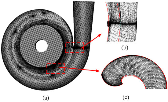
Figure 5.
Details of the generated mesh grids: (a) the mesh model of the pump; (b) the refined mesh model in the volute tongue; (c) the refined mesh model in an impeller inlet.
Theoretically, with an increase in grid number, the errors of simulation may decrease. However, grid numbers with large quantities would be influenced due to computational resources and time [28]. So, different grid numbers are examined to ensure the independence of the numerical solution. Consequently, three grid-schemes named Grid-1, Grid-2, and Grid-3 are used for flow calculations. The grid numbers are 193,268, 341,456, and 721,138, respectively. Additionally, the corresponding maximum cell sizes are 0.07 mm, 0.05 mm, and 0.02 mm. The pump head and efficiency are predicted under different flow rate conditions. The pump performance with different mesh elements is list in Table 3.
Table 3.
Pump performance with different mesh elements.
This indicates that the results are influenced gradually by increasing the grid numbers and that the overall error in percentage is within 2%. The head and efficiency of Grid-1 are biggest among three grid-schemes, and the results of Grid-2, and Grid-3 are close together. Due to this, the simulation results tend to be close, the grid number has a slight effect on the pump head and efficiency. So, Grid-2 is finally selected for the following simulations, because of its solution efficiency.
3.2. Numerical Method and Simulation Conditions
The numerical simulation is performed by commercial software, i.e., PUMPLINX. A series of turbulence models can be selected in the software, where the RNG κ-ε turbulence model [29] is selected to simulate the flow field. The simulation conditions are as follows:
- The pressure is set as the inlet condition, of which the total pressure is prescribed. A given mass flow is imposed at the outlet boundary.
- The fluid is aero-fuel with a density of 779 kg/m3. The temperature for all the regions is set as 20℃ and the kinematic viscosity is 1.48 m2/s.
- The rotating domain of the impeller is a stationary domain with a rotating reference frame. The interface between the impeller and the volute is connected by the technique of the frozen rotor method. Moreover, the blade surfaces, hub, and shroud are set as solid walls. They satisfy the non-slip condition.
- The SIMPLE algorithm is used to solve the pressure-velocity coupling equation. The convergence precisions of all residuals are below the criterion of 1 × 10⁻⁵.
3.3. Experiment Setup
Figure 6 shows the experimental setup. In Figure 6a, the experimental pump is manufactured in a pump company in Shaanxi Province. Figure 6b shows the schematic diagram. Figure 6c illustrates the experimental apparatus. It consists of (1) a fuel supply section (a fuel tank, a crude fuel filter, and an inlet regulating valve); a (2) pump section (an experimental centrifugal pump and an electric motor); (3) a fuel regulating section (a pressure sensor, pressure gauge, flow meter, temperature sensor, electric throttle valve, manual throttle valve, and an overflow valve).
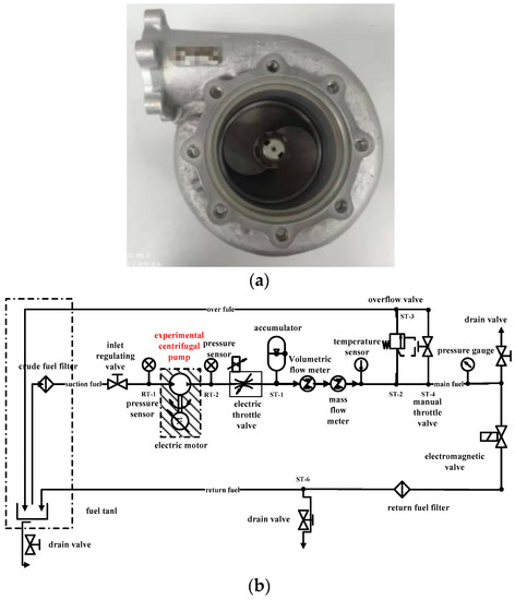
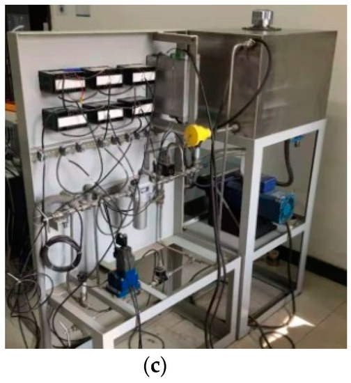
Figure 6.
Experimental setup: (a) experimental pump; (b) schematic diagram; (c) experimental apparatus.
The flow rates and rotor speeds of the pump are obtained under the standard atmosphere condition. In order to predict head and efficiency, the inlet pressure and outlet pressure are tested by related pressure sensors.
3.4. Turbulence Model Verification
To prove the probability of the selected RNG k-ε turbulence model for the studied pump simulation, the simulations are performed at different flow rates, while the rotor speed is set as Nd. Additionally, an experimental pump is manufactured and tested in a pump company in Shaanxi Province, where the company is a participant in this paper (the information of experiment is shown in Section 5). Based on simulation and experiment results, the head H and efficiency ηv are predicted and obtained as:
where Pin is the pump inlet pressure, Pc is the pump outlet pressure, and is height difference between the inlet and outlet of the pump.
where P is the shaft power.
The H and ηv of the simulation are in acceptable agreement with the experiment in all cases. The minimum relative errors between simulation and experiment are 0.8% and 1.2% for head and efficiency, so they nearly coincide at Qd. The maximum relative errors are within 5% when the pump is operating at the low flow rates. Therefore, the performance of the studied pump can be effectively predicted with the setting numerical method.
4. Simulation Results and Discussions
In this section, the detailed flow characteristics are obtained and performances are demonstrated in the following simulations. Firstly, the static pressure and relative velocity distributions of the studied pump at the axial section are demonstrated in Figure 7. Secondly, the effects of combination impeller on the flow flied are illustrated in Figure 8, Figure 9, Figure 10 and Figure 11, respectively. Finally, under the simulation conditions, the external performances of the pump with a combination and conventional impeller are predicted and compared, as shown in Figure 12. The external performance curves for the studied pump under different operating conditions are shown in Figure 13.
Figure 7.
Static pressure and relative velocity distributions at the axial section of the combination impeller: (a) static pressure, 0.8Qd; (b) static pressure, 1.0Qd; (c) static pressure, 1.2Qd; (d) relative velocity, 0.8Qd; (e) relative velocity, 1.0Qd; (f) relative velocity, 1.2Qd.
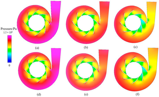
Figure 8.
Static pressure and relative velocity distributions at the axial section: (a) combination impeller, 0.8Qd; (b) combination impeller, 1.0Qd; (c) combination impeller, 1.2Qd; (d) conventional impeller, 0.8Qd; (e) conventional impeller, 1.0Qd; (f) conventional impeller, 1.2Qd
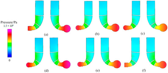
Figure 9.
Comparisons of static pressure distributions at the radial section between the combination impeller and the conventional impeller: (a) combination impeller, 0.8Qd; (b) combination impeller, 1.0Qd; (c) combination impeller, 1.2Qd; (d) conventional impeller, 0.8Qd; (e) conventional impeller, 1.0Qd; (f) conventional impeller, 1.2Qd.
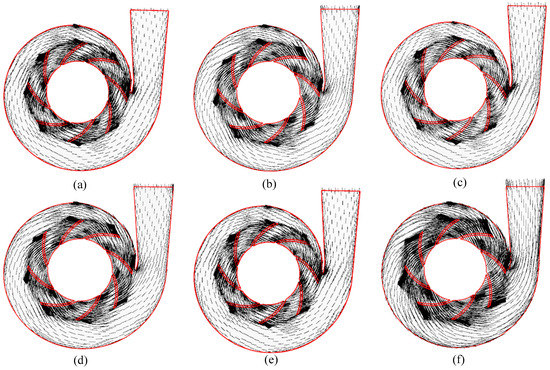
Figure 10.
Comparisons of velocity vectors at the axial section between the combination impeller and the conventional impeller: (a) combination impeller, 0.8Qd; (b) combination impeller, 1.0Qd; (c) combination impeller, 1.2Qd; (d) conventional impeller, 0.8Qd; (e) conventional impeller, 1.0Qd; (f) conventional impeller, 1.2Qd.
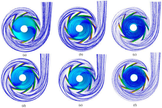
Figure 11.
Comparisons of the pathlines between the combination impeller and the conventional impeller: (a) combination impeller, 0.8Qd; (b) combination impeller, 1.0Qd; (c) combination impeller, 1.2Qd; (d) conventional impeller, 0.8Qd; (e) conventional impeller, 1.0Qd; (f) conventional impeller, 1.2Qd.
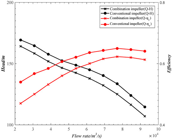
Figure 12.
Comparisons of the performance curves.
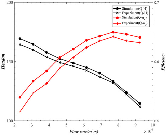
Figure 13.
External performance curves of the studied pump.
4.1. Detailed Flow Characteristics of the Studied Pump
Flow field in the pump is simulated at different flow rates. Figure 7 indicates the distributions of static pressure and the relative velocity at 0.8Qd, 1.0Qd and 1.2Qd, when the pump is operating at the nominal rotor speed Nd.
As shown in Figure 7a–c, from the pump inlet to the outlet, pressure increases gradually, and the minimum pressure occurs at the leading edge of the blade suction surface. The pressure gradient distributes similarly between the two blade surfaces. However, caused by the action of fluid motion, compared to the pressure on suction surface, the pressure is higher on the pressure surface at the related same position. Unfortunately, a small area of the impeller outlet appears secondary to the flow loss. Meanwhile, asymmetry flow fields emerge in each impeller channel and it performs more strictly at a larger flow rate. Besides, due to the rotor–stator interaction, an asymmetry flow in volute is also observed. Furthermore, the pressure near the volute tongue presents severely because of the flow obstruction, where a large pressure gradient appears at the large rate. Note that the change trend of pressure distribution is consistent at the five flow rates.
The relative velocity distributions of pump are demonstrated in Figure 7d–f. The relative velocity distributes uniformly in the pump. The change trends of velocity distributions are consistent in all cases where the velocity gradually increases in the impeller and decreases in the volute. The minimum velocity with a gradient appears at the impeller inlet, and, compared to the velocity on the suction surface, the velocity on the pressure surface is higher. Much like the pressure distribution, the velocity near the volute tongue presents severely, which will lead to a certain hydraulic loss.
Relying on the above observations, it indicates that the pressure gradient appears on the blade surfaces. Asymmetric flow fields emerge in each impeller channel. The hydraulic loss exists within a certain region in the impeller inlet, the impeller outlet, and the volute tongue, respectively. Therefore, some flow instabilities exist in the centrifugal pump, which is a coincident with the conclusion indicted in [30,31,32].
4.2. Effects of the Combination Impeller on the Flow Field inside the Impeller and the Volute
Simulation results of static pressure, the relative velocity vector, and fluid streamline are displayed in Figure 8, Figure 9, Figure 10 and Figure 11. Here, the pump is operating at 0.8Qd, 1.0Qd, 1.2Qd and the nominal rotor speed Nd.
Figure 8 shows the comparisons of static pressure distributions at the axial section between the combination and conventional impellers. In an impeller, the pressure increases from the inlet to the outlet at the three flow rates, and it distributes uniformly at the two blade surfaces. Moreover, the pressure gradient of combination impeller is higher than that of a conventional impeller, which is observed more obviously at the lower flow rate. So, it may improve the utilization of the kinetic energy by using a combination impeller. Additionally, attributed to the jet-wake flow at the impeller outlet, a certain secondary flow loss appears at both the two impellers. The corresponding area of secondary flow is lower in the combination impeller. On the other hand, it is obvious that the asymmetric flow gets better in the combination impeller passage, so a less local loss is realized. In the volute, the pressure decreases when the flow rate increases, while it increases along the volute to the pump outlet. So, the kinetic energy can be converted into static pressure as a way of minimizing losses. Compared to a conventional impeller, the pressure distribution of a combination impeller is more uniform inside the volute. Unfortunately, due to the jet-wake flow from the impeller outlet, an asymmetric flow appears near the interface between the impeller and the volute. So, there is a certain pressure loss inside the volute. It was also observed that the most pressure loss appears near the volute tongue. The extent of the pressure loss reduces with the use of a combination impeller, which means the effect of the rotor–stator interaction gets weak. Clearly, the combination impeller can effectively regulate the flow inabilities in the volute tongue.
Now, quantitative flow characteristics at the combination region cannot be obtained. So, to obtain a qualitative assessment, the location and size of the separation zone must be observed alternatively. For such cases, the static pressure distributions at the radial section of the combination and conventional impellers are shown in Figure 9. So, the flow characteristics in the combination region can be illustrated. The fuel is introduced into the pump inlet and then its pressure increases in the impeller. The highest pressure occurs at the small flow rate with the largest gradient among the five flow rates. However, a vortex flow appears in the combination region, which leads a certain vortex loss. In particular, the impeller efficiency can be improved by decreasing the vortex loss in the region with the combination impeller. So, it indicates that it is effective for the centrifugal pump to control the flow characteristics by using a combination impeller.
To observe the velocity distribution clearly, Figure 10 demonstrates the velocity vector at the axial section. The velocity increases in the impeller at the five flow rates and is distributed uniformly at the blade surfaces. However, at the impeller outlet, a small area appears with obvious high-velocity flow patterns. The region is smaller in the combination impeller than that in the conventional impeller, so it is found that combination impeller can decrease hydraulic loss at the impeller outlet. Furthermore, due to the circumferential flow in the impeller, it is inevitable for the impeller to occur the region of back flow. A back flow appears at the inlet of pressure suction, which occupies a majority of the impeller channel. Consequently, the fluid flows obstructively to the impeller outlet due to the limited region near the suction side. It has an adverse effect on the hydraulic performance. In two impellers, the back-flow region near the pressure side of the long auxiliary blade is moved to a mid-position. Distinctively, it becomes smaller in the combination impeller. At the large flow rate, between the pressure side of the main blade and the suction side of long auxiliary blade, the back-flow region in the combination impeller has already disappeared. In addition, due to the diffusion structure of the volute, the velocity decreases gradually when fuel flows into the volute. The velocity decreases along the volute to the diffuser outlet at the five flow rates. Due to the impeller outlet causing the jet-wake flow, an obvious high-velocity flow pattern appears in the region. Compared to a conventional impeller, the area is smaller in combination impellers. Consequently, it illustrates that it is helpful to reduce the hydraulic loss in the volute for the aero-fuel centrifugal pump by using the combination impeller.
To uncover the detailed flow characteristics in the impeller and volute legibly, the fluid pathlines are illustrated in Figure 11. In all the cases, the pathlines with a helix pattern exhibit in the suction pipe with a clockwise rotational direction. The angle of the helix pattern is decreased with an increased flow rate, and it is smaller in the combination impeller than that in conventional impeller. So, in combination impeller, the swirling flow is nearly disappeared in the suction pipe. It ensures that the inlet operating condition is acceptable. Moreover, in the combination region, it is obviously observed that the pathlines distribute more uniformly in a combination impeller, so that the hydraulic energy can be utilized more effectively. Despite the above superiority of the pathlines in the combination impeller, a certain flow loss occurs in the impeller outlet, which is attributed to the secondary flow. In the volute pipe, streamlines also exhibit a helix pattern in all cases. Nevertheless, a swirling flow in volute is observed in the volute tongue, and it performs seriously in the conventional impeller.
4.3. Effects of the Combination Impeller on the External Performance
According to the above analysis, it is concluded that the combination impeller has an important effect on the flow characteristics in certain regions, such as: the impeller inlet, the impeller outlet, and the volute tongue. To identify the flow characteristics quantitatively, the external performances of the two pumps are predicted according to Equations (1) and (2). Figure 12 illustrates the comparisons of performance curves (Q-H, Q-ηv). The change trends of head H and efficiency ηv are relatively consistent to each other. Importantly, the best efficiency point (BEP) of the studied pump occurs at Qd (77,000 L/h, where its highest efficiency and head are 0.65 and 133 m, respectively. So, the external performances of the studied pump are in good agreement with the performance requirements. And they are both higher than those of the pump with the conventional impeller. In addition, the high efficiency region of the pump with the combination impeller is wider near Qd. So, it is able to operate stably over the entire operating range, especially at the off-nominal flow rates. Consequently, it is a promising approach in improving the external performance by applying the combination impeller to an aero-fuel centrifugal pump, which corresponds to the effect on the flow field.
Moreover, in order to realize the external performance of the studied pump, the external performance experiments are given. Figure 13 shows the external performance curves for the studied pump under different operating conditions. When the pump is operating at Nd, the results between simulation and experiment are very close, within a relative error of 5%. It illustrates that the external performance of the experiment is in good agreement with that of the simulation. Importantly, the BEP occurs at Qd (77,000 L/h) and the highest efficiency of the pump is 0.65, which nearly coincides with the conclusion indicted in Figure 12. In addition, the high efficiency region is wide near the nominal operating point. Therefore, the studied centrifugal pump is stable when operating under a large condition range, especially under off-nominal operating conditions. It is verified that the aero-fuel centrifugal pump with the combination impeller has an ability to achieve the technical requirements at a large nominal operating flow rate (77,000 L/h), and it has an active effect on energy saving due to its high efficiency working.
5. Conclusions
In this paper, the numerical simulation and experiment of an aero-fuel centrifugal pump with a combination impeller are conducted. The numerical method is validated by comparing the simulation results with one’s own experimental data, then the flow field is simulated and the external performance is predicted. The conclusions are as follows:
(1) The results of the simulation and experiment are very close, within a relative error of 5% when the pump is operating at Nd. It illustrates that the external performances of the simulation are in good agreement with the experiment.
(2) The hydraulic losses inside the impeller and volute can be decreased when the pump is equipped with the combination impeller. In particular, the flow instabilities in the impeller inlet, impeller outlet, and volute tongue are significantly regulated. In addition, the predicted head and efficiency of the pump with the combination impeller are both higher than those of the pump with the conventional impeller.
(3) The BEP of the pump with the combination impeller occurs at Qd (77,000 L/h) and the highest efficiency is 0.65. It is stable with high efficiency over the entire operating range. It illustrates that the pump has an ability to achieve the technical requirements at the large nominal operating flow rate (77,000 L/h), and it has an active effect on energy saving because of its high working efficiency.
The demonstrated results show the effectiveness and reliability of the studied pump to regulate the flow characteristic and external performance. However, the study on anti-cavitation for the pump has not yet been considered, so it is one of our future works.
Author Contributions
Data curation, X.W.; Formal analysis, Y.W.; Funding acquisition, W.W.; Investigation, J.L.; Methodology, B.C.; Resources, X.C.; Writing—original draft, J.L.; Writing—review & editing, J.L. All authors have read and agreed to the published version of the manuscript.
Funding
This research was funded by the National Natural Science Foundation of China (No. 51506177) and the Fundamental Research Funds for the Central Universities of Chang’ an University (No. 300102259101).
Acknowledgments
The authors gratefully acknowledge the financial support of the National Natural Science Foundation of China, the Fundamental Research Funds for the Central Universities of Chang’ an University.
Conflicts of Interest
The authors declare no conflict of interest.
References
- Liu, S.Q. Investigation of centrifugal pump used as aero-engine main fuel pump. Aeroengine 2006, 32, 43–45. [Google Scholar]
- Sutton, G.P. History of Liquid Propellant Rocket Engines in the United States. J. Propuls. Power 2003, 19, 978–1007. [Google Scholar] [CrossRef]
- Koyama, N. Utilization of Centrifugal Pumps Used as Hydraulic Turbines. J. Soc. Mech. Eng. 1971, 74, 1584–1587. [Google Scholar]
- Arriaga, M. Pump as turbine–a pico-hydro alternative in Lao People’s Democratic Republic. Renew. Energy 2010, 35, 1109–1115. [Google Scholar] [CrossRef]
- Petrone, G.; De Nicola, C.; Quagliarella, D.; Witteveen, J.; Iaccarino, G. Wind Turbine Performance Analysis Under Uncertainty. In Proceedings of the 49th AIAA Aerospace Sciences Meeting including the New Horizons Forum and Aerospace Exposition, Orlando, FL, USA, 4–7 January 2011; pp. 544–556. [Google Scholar]
- Zhang, J.; Kong, L.; Qu, J.; Wang, S.; Qu, Z. Numerical and experimental investigation on configuration optimization of the large-size ionic wind pump. Energy 2019, 171, 624–630. [Google Scholar] [CrossRef]
- Stepanoff, A.J. Centrifugal and Axial Flow Pumps, Design and Applications; John Wiley and Sons: New York, NY, USA, 1957. [Google Scholar]
- Shen, Z.; Chu, W.; Li, X.; Dong, W. Sediment erosion in the impeller of a double-suction centrifugal pump—A case study of the Jingtai Yellow River Irrigation Project, China. Wear 2019, 422, 269–279. [Google Scholar] [CrossRef]
- Fan, S.Q. Aeroengine Control; Northwestern Polytechnical University Press: Xi’an, China, 2008. [Google Scholar]
- Jiang, Q.; Heng, Y.; Liu, X.; Zhang, W.; Bois, G.; Si, Q. A Review of Design Considerations of Centrifugal Pump Capability for Handling Inlet Gas-Liquid Two-Phase Flows. Energies 2019, 12, 1078. [Google Scholar] [CrossRef]
- Han, W.; Nan, L.; Su, M.; Chen, Y.; Li, R.; Zhang, X. Research on the Prediction Method of Centrifugal Pump Performance Based on a Double Hidden Layer BP Neural Network. Energies 2019, 12, 2709. [Google Scholar] [CrossRef]
- Yan, P.; Chu, N.; Wu, D.; Cao, L. Computational fluid dynamics-based pump redesign to improve efficiency and decrease unsteady radial forces. J. Fluids Eng. 2017, 139, 011101. [Google Scholar] [CrossRef]
- Cao, L.; Zhang, Y.; Wang, Z.; Xiao, Y. Effect of axial clearance on the efficiency of a shrouded centrifugal pump. J. Fluids Eng. 2015, 137, 071101. [Google Scholar]
- Dönmez, A.H.; Yumurtacı, Z.; Kavurmacıoğlu, L. The effect of inlet blade angle variation on cavitation performance of a centrifugal pump: A parametric study. J. Fluids Eng. 2019, 141, 021101. [Google Scholar]
- Zhou, L.; Shi, W.; Li, W.; Agarwal, R. Numerical and Experimental Study of Axial Force and Hydraulic Performance in a Deep-Well Centrifugal Pump With Different Impeller Rear Shroud Radius. J. Fluids Eng. 2013, 135, 104501. [Google Scholar] [CrossRef]
- Jafarzadeh, B.; Hajari, A.; Alishahi, M.M.; Akbari, M. The flow simulation of a low-specific-speed high-speed centrifugal pump. Appl. Math. Model. 2011, 35, 242–249. [Google Scholar] [CrossRef]
- Shojaeefard, M.H.; Tahani, M.; Ehghaghi, M.B.; Fallahian, M.A. Numerical study of the effects of some geometric characteristics of a centrifugal pump impeller that pumps a viscus fluid. Comput. Fluids 2012, 60, 61–70. [Google Scholar] [CrossRef]
- Guo, X.; Zhu, L.; Zhu, Z.; Cui, B.; Li, Y. Numerical and experimental investigations on the cavitation characteristics of a high-speed centrifugal pump with a splitter-blade inducer. J. Mech. Sci. Technol. 2015, 29, 259–267. [Google Scholar] [CrossRef]
- Luo, X.; Zhang, Y.; Peng, J.; Xu, H. Impeller inlet geometry effect on performance improvement for centrifugal pumps. J. Mech. Sci. Technol. 2018, 22, 1971–1976. [Google Scholar] [CrossRef]
- Lundgreen, R.K.; Oliphant, K.; Maynes, D.; Gorrell, S.E. High Suction Performance Pumps with Large Inlet Blade Angles and an Integrated Stability Control Device. In Proceedings of the 52nd AIAA/SAE/ASEE Joint Propulsion Conference, Salt Lake City, UT, USA, 25–27 July 2016; Volume 2016, pp. 4985–4999. [Google Scholar]
- Chen, H.-X.; He, J.-W.; Liu, C. Design and experiment of the centrifugal pump impellers with twisted inlet vice blades. J. Hydrodyn. 2017, 29, 1085–1088. [Google Scholar] [CrossRef]
- Ayad, A.F.; Abdalla, H.M.; Aly, A.A.E.-A. Effect of semi-open impeller side clearance on the centrifugal pump performance using CFD. Aerosp. Sci. Technol. 2015, 47, 247–255. [Google Scholar] [CrossRef]
- Yousefi, H.; Noorollahi, Y.; Tahani, M.; Fahimi, R.; Saremian, S. Numerical simulation for obtaining optimal impeller’s blade parameters of a centrifugal pump for high-viscosity fluid pumping. Sustain. Energy Technol. Assess. 2019, 34, 16–26. [Google Scholar] [CrossRef]
- Hong, S.S.; Kim, D.J.; Kim, J.S.; Choi, C.H. Study on inducer and impeller of a centrifugal pump for a rocket engine turbopump. J. Mech. Eng. Sci. 2013, 227, 311–319. [Google Scholar] [CrossRef]
- Guo, X.-M.; Zhu, Z.-C.; Shi, G.-P.; Huang, Y. Effects of rotational speeds on the performance of a centrifugal pump with a variable-pitch inducer. J. Hydrodyn. 2017, 29, 854–862. [Google Scholar] [CrossRef]
- Li, W.-G. Effects of viscosity on turbine mode performance and flow of a low specific speed centrifugal pump. Appl. Math. Model. 2016, 40, 904–926. [Google Scholar] [CrossRef]
- Stechmann, D.; Sese, C.; Duvvur, R.; Huang, Y.; Bilyeu, M.; Goldberg, D.; King, M.; Zhang, A.; Pourpoint, T.L. Design and Analysis of a High-Pressure Turbopump at Purdue University. In Proceedings of the 51st AIAA/SAE/ASEE Joint Propulsion Conference, Orlando, FL, USA, 27–29 July 2015; Volume 2015, pp. 4216–4240. [Google Scholar]
- Wang, C.; Shi, W.; Wang, X.; Jiang, X.; Yang, Y.; Li, W.; Zhou, L. Optimal design of multistage centrifugal pump based on the combined energy loss model and computational fluid dynamics. Appl. Energy 2017, 187, 10–26. [Google Scholar] [CrossRef]
- Song, Y.; Fan, H.; Zhang, W.; Xie, Z. Flow Characteristics in Volute of a Double-Suction Centrifugal Pump with Different Impeller Arrangements. Energies 2019, 12, 669. [Google Scholar] [CrossRef]
- Tan, L.; Zhu, B.S.; Cao, S.L.; Bing, H. Influence of blade wrap angle on centrifugal pump performance by numerical and experimental study. Chin. J. Mech. Eng. 2015, 27, 171–177. [Google Scholar] [CrossRef]
- Ding, H.; Li, Z.; Gong, X.; Li, M. The influence of blade outlet angle on the performance of centrifugal pump with high specific speed. Vacuum 2019, 159, 239–246. [Google Scholar] [CrossRef]
- Han, X.; Kang, Y.; Li, D.; Zhao, W. Impeller Optimized Design of the Centrifugal Pump: A Numerical and Experimental Investigation. Energies 2018, 11, 1444. [Google Scholar] [CrossRef]


© 2020 by the authors. Licensee MDPI, Basel, Switzerland. This article is an open access article distributed under the terms and conditions of the Creative Commons Attribution (CC BY) license (http://creativecommons.org/licenses/by/4.0/).