Article

Floating Performance of a Composite Bucket Foundation with an Offshore Wind Tower during Transportation

1
State Key Laboratory of Hydraulic Engineering Simulation and Safety, Tianjin University, Tianjin 300072, China
2
Key Laboratory of Coast Civil Structure Safety (Tianjin University), Ministry of Education, Tianjin 300072, China
*
Author to whom correspondence should be addressed.
Energies 2020, 13(4), 882; https://doi.org/10.3390/en13040882
Submission received: 7 January 2020 / Revised: 1 February 2020 / Accepted: 13 February 2020 / Published: 17 February 2020

Abstract

:
The composite bucket foundation (CBF) for offshore wind turbines is the basis for a one-step integrated transportation and installation technique, which can be adapted to the construction and development needs of offshore wind farms due to its special structural form. To transport and install bucket foundations together with the upper portion of offshore wind turbines, a non-self-propelled integrated transportation and installation vessel was designed. In this paper, as the first stage of applying the proposed one-step integrated construction technique, the floating behavior during the transportation of CBF with a wind turbine tower for the Xiangshui wind farm in the Jiangsu province was monitored. The influences of speed, wave height, and wind on the floating behavior of the structure were studied. The results show that the roll and pitch angles remain close to level during the process of lifting and towing the wind turbine structure. In addition, the safety of the aircushion structure of the CBF was verified by analyzing the measurement results for the interaction force and the depth of the liquid within the bucket. The results of the three-DOF (degree of freedom) acceleration monitoring on the top of the test tower indicate that the wind turbine could meet the specified acceleration value limits during towing.

Graphical Abstract

1. Introduction

The amount of energy produced by offshore wind turbines is expected to increase significantly in the coming years, as offshore wind turbines become more profitable. At the end of 2018, the share of the total global offshore installations represented 4% of the 591 Gigawatt (GW) total installed wind turbine capacity. By 2025, their share is expected to exceed 10% and the total installed base could reach 100 GW. In China, the government’s sustainable development policy is promoting a gradual transition from conventional energy sources to renewable energy sources. Since the completion of the first offshore wind farm, the Donghai Bridge project in Shanghai, China has accumulated rich experience in offshore wind power over the past 10 years. In 2018, China installed 1.8 GW offshore wind turbines, taking the lead of offshore wind market for the first time [1].
However, offshore wind power in China is still in the early stage of a large-scale development. Improving technical quality and building the industrial chain, as well as quickly realizing parity, are both important and challenging. The construction period and costs of offshore wind turbines are still much greater than those of onshore wind turbines due to the limitation of the window periods for offshore construction. Traditionally, the construction process of an offshore wind turbine is divided into two parts: foundation construction and wind turbine (tower, nacelle, and rotor) hoisting. Such a construction method is easily affected by wind, waves, currents, and other environmental loads during the hoisting process. What is more, the installation of foundations (such as the piling of single pile and the hoisting of jacket foundation) and the hoisting of wind turbines require a large floating crane or a jack-up hoisting platform. With the increase in offshore wind turbine capacity and installation water depth, the requirements for construction equipment also increase. The limitation offshore construction capacity and construction equipment also restrict the large-scale development of offshore wind power in China [2,3,4,5,6].
The bucket foundation, as a new type of offshore foundation, has become an emerging research hotspot in the field of offshore wind power due to its characteristics of high efficiency, low cost, resource saving, and environmental friendliness [7,8,9]. Combined with the advantages of traditional bucket foundations and gravity foundations and considering the geological characteristics (soft clay, silty clay and find sand) of wind farms of china, a new type of wide-shallow foundation and one-step transportation and installation method for the foundation, called the large-scale composite bucket foundation (CBF), was proposed by Tianjin University and Daoda Company, as shown in Figure 1. The CBF is composed of an arcing transition of reinforced concrete, a beam-plate system, and a honeycomb bucket. The arc transition ensures that the various loads from the upper tower structure are successfully transmitted into the foundation and converted into small tensile and compressive stresses. A series of studies on the bearing capacity and dynamic response of CBFs have proved that CBFs have great advantages for bearing the large bending moment loads from wind turbines [10,11,12,13,14,15]. As of October 2010, the first CBF for a fully operational wind turbine was installed at the offshore test facility in Qidong City, in the eastern part of Jiangsu Province. The wind turbine is a XEMC 2.5 MW turbine with an 80 m hub height. The diameter and the bucket skirt length of the CBF are 30 and 7 m, respectively, with a total foundation weight of nearly 2200 t and an 18 m arc transition structure of pre-stressed concrete [2].
There are seven rooms inside the CBF arranged in a honeycomb structure. The six peripheral rooms with the skirt have the same proportions, while the middle orthohexagnal one is a little larger. With the seven-room structure, the CBF has reasonable motion characteristics and towing reliability during the wet-tow construction process. During the installation process, the pressure of different compartments can also be adjusted for leveling. In addition, the one-step transportation and installation of CBFs and wind turbines can be realized. As shown in Figure 2, the construction process for a CBF can be divided into four main steps: prefabricating the foundation onshore, hoisting wind turbine and commissioning tests on shore, and loading and transporting the wind turbine and its foundation, followed by suction sinking and leveling of one-step installation [16,17,18,19,20,21]. Compared to conventional construction methods for offshore wind turbines, CBFs have the following advantages:
(1)
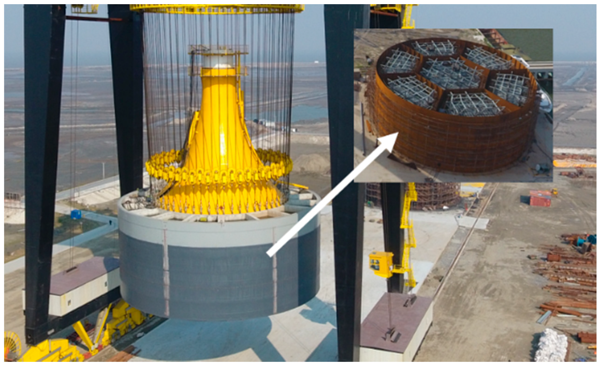
Since the foundation is prefabricated on land, construction quality can be more easily and effectively controlled.
(2)
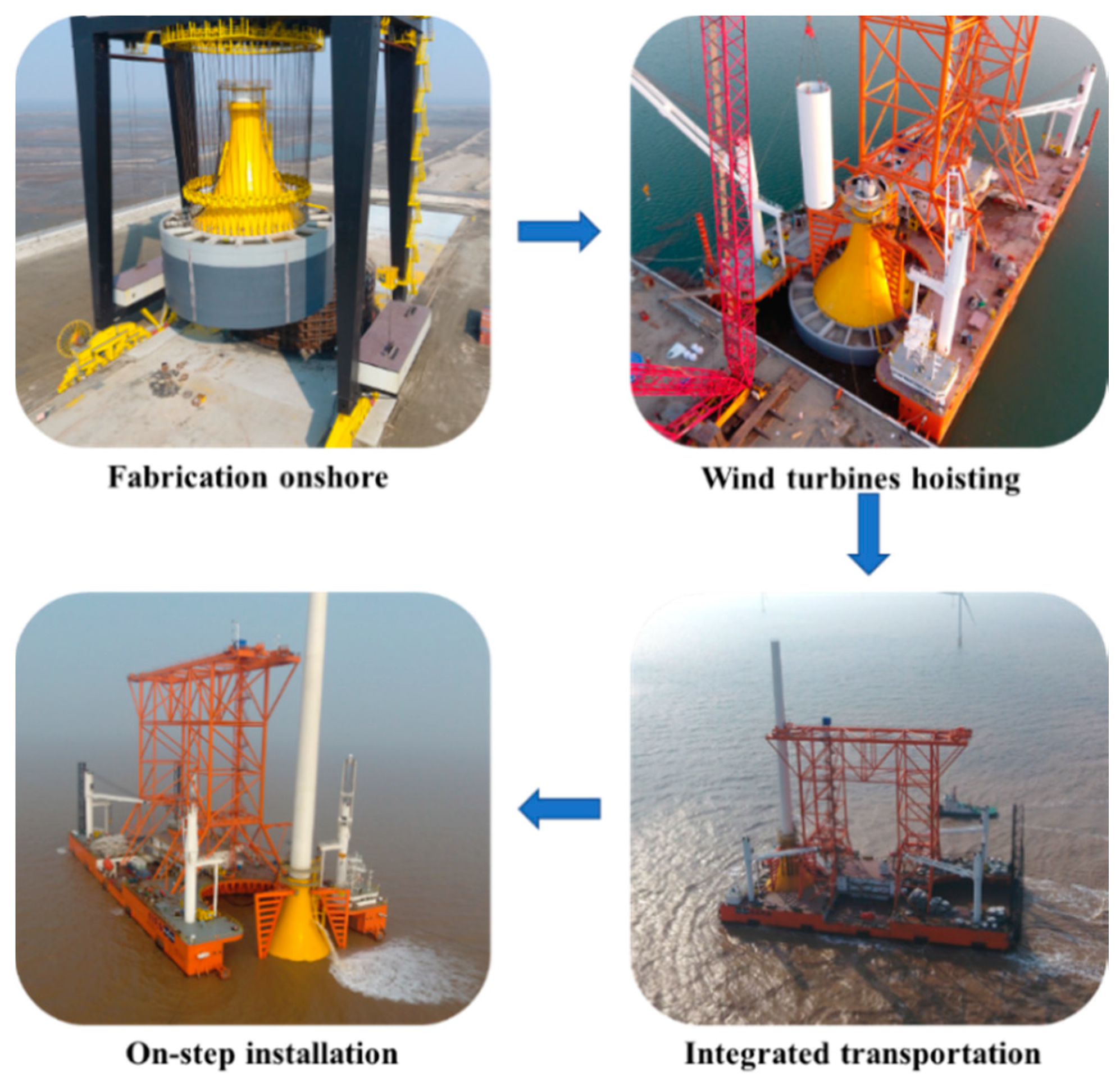
Due to the simplified construction process and greatly shortened offshore construction time, the window periods for offshore construction are increased substantially.
(3)
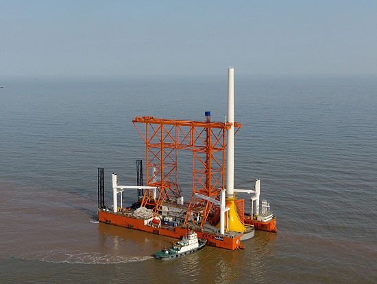
Just like “Tree Planting”, the integrated transportation-installation techniques reduce the need for large-scale offshore installation equipment, which can save cost compared with traditional technologies.
(4)
Because there are no driven pilings or other offshore construction process, the construction noise is minimized. In addition, the CBF can be recovered and moved as a whole, which can reduce construction waste and improve recovery of materials.
The bucket of a CBF is divided into seven compartments by bulkheads, forming a honeycomb subdivision structure. Enough compressed air is pumped into the seven compartments to generate buoyancy, which not only balances the weight of the CBF but also generates net a buoyancy of about 500 tf. The net buoyancy generates pre-pressure between the bottom of the vessel and the top of the beam-plate system, ensuring that the vessel and CBF will not move in relation to each other. In addition, there are also several wire ropes between the vessel and the CBF as a safeguard. As a result, the vessel and CBF are tightly connected so the “CBF carries the vessel”, as shown in Figure 3.
The air cushion structure of the CBF and its special binding method with the vessel make it different from other floating structures for towing. Researchers all over the world have studied the air cushion effect on floating bodies for several years. Pinkster et al. [22,23] studied the motion of partially supported and fully supported structures in waves through 3D potential theory, and these results are in good agreement with the results of model tests conducted by Tabeta [24]. Malenica and Zalar extended the Pinkster method and calculated and analyzed the hydrodynamic coefficient of the aircushion supporting structure [25]. Thiagarajan et al. studied the wave response of air-floating structures in shallow water by theoretical analysis and model tests [26,27]. The results of Chenu et al. showed that the presence of the air cushion reduced the stability of the structure and changed the natural vibration frequency and additional mass of the structure, confirming that the air cushion structure challenged the accepted assessment of the metacentric height for floating ships with an internal free liquid level [28]. Ikoma et al. have studied the motion and wave drift forces of aircushion support structures under regular waves [29] and, in recent studies, have extended their work to the field of hydroelasticity [30,31]. As a floating structure with air cushion, the CBF is equal to the structure supported on the spring coupled by the compressible air and water. Since the elastic stiffness of the air spring is smaller than that of the water spring, the resistance of the floating body with an air cushion is less than the resistance of the ordinary floating body with the same draft. As a result, the stability of the floating body with an air cushion may be less than that of the ordinary floating body [32,33,34]. In the towing process, in addition to paying attention to the motion response of the structure, the emphasis should also be placed on the air cushion and the interaction forces’ response.
The application of the one-step transportation and installation for CBFs can be divided into three stages, which is to verify the feasibility of this technology on the premise of ensuring the safety of wind turbine structure during transportation and installation. Firstly, the initial towing test used a test tower (excluding nacelle, hub, and blade) to verify that the acceleration of the turbine structures met the requirements during the towing process. Secondly, the transport test of one single CBF with wind turbines (including tower, nacelle, hub, and blade) was carried out. Finally, two CBFs with wind turbines were transported. This paper focuses on the first stage and the floating behavior during the transportation of the CBF with a test tower for the Xiangshui wind farm, which is monitored. The influences of transport speed in the water, wave height, and wind on the floating behavior of the whole structure is described. The second part of the paper introduces the transport prototype, monitoring equipment, and the selection of environmental load conditions. The third part analyzes the measurement results.

2. Towing Transport Setup

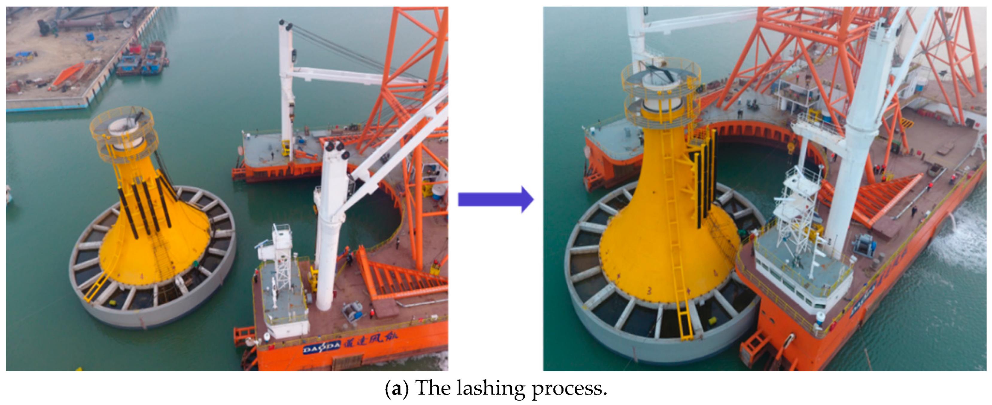
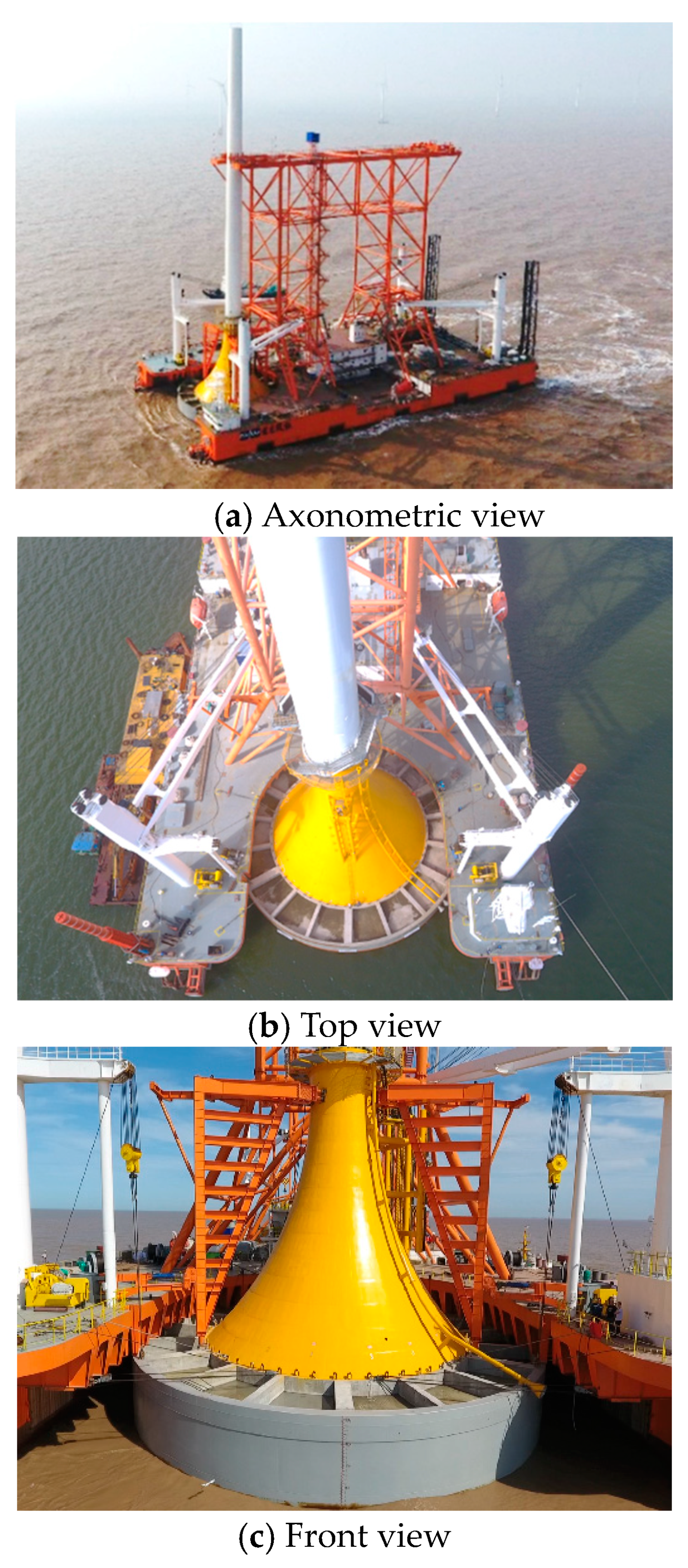
2.1. Prototype of the Integrated Transport System

The destination of the measured transportation process is an offshore wind farm that is 10 km off the coast of the Yellow Sea in China. The total maritime transport time is 112 h, the sailing distance is 290 nautical miles, and the average speed is 2.6 knots. As shown in Figure 4, the tested process uses a one-step transport and installation vessel (OSTIV), the CBF, and the turbine tower. The parameters of the overall structure are listed in Table 1.
The main uses of the OSTIV are to assist with hoisting and commissioning the wind turbine on shore, loading and transporting the wind turbines and CBFs, and installing these components. The vessel is concave at the prow and stern in order to install CBFs and offshore wind turbines. The concave bow area is divided into two layers. The midship area is fitted with a truss structure, which is equipped to hold a turbine’s tower. The holding device is used to stabilize the CBFs and wind turbines.
The OSTIV is equipped with two main propellers, two side thrusters, and a GPS ship positioning system, which can position the vessel precisely. It is also equipped with the monitoring, control, and early warning system for sinking and leveling the CBF. It can monitor and regulate, in real time, the air pressure inside the bucket and the inclination of the foundation during the CBF transportation and sinking procedure.

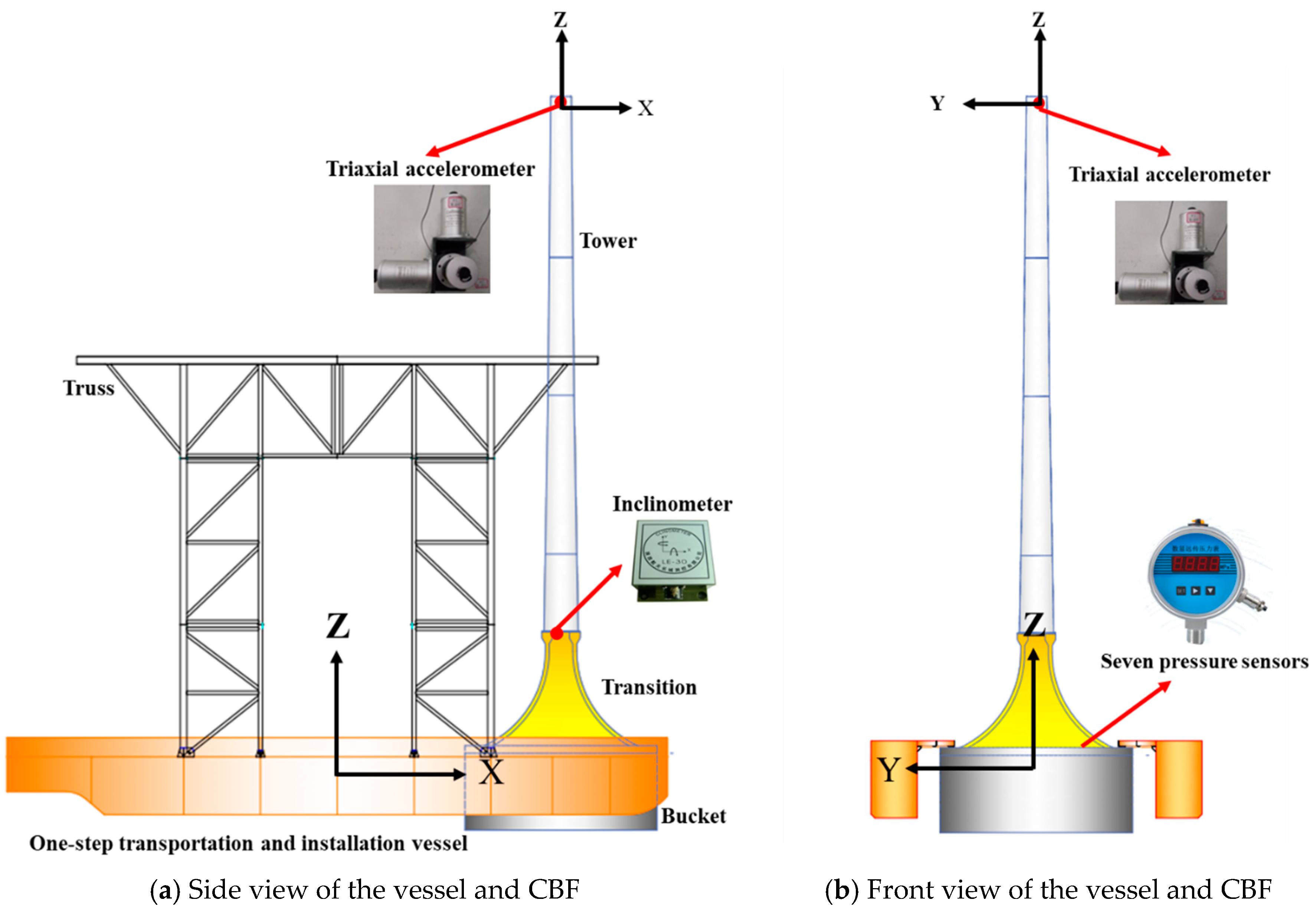
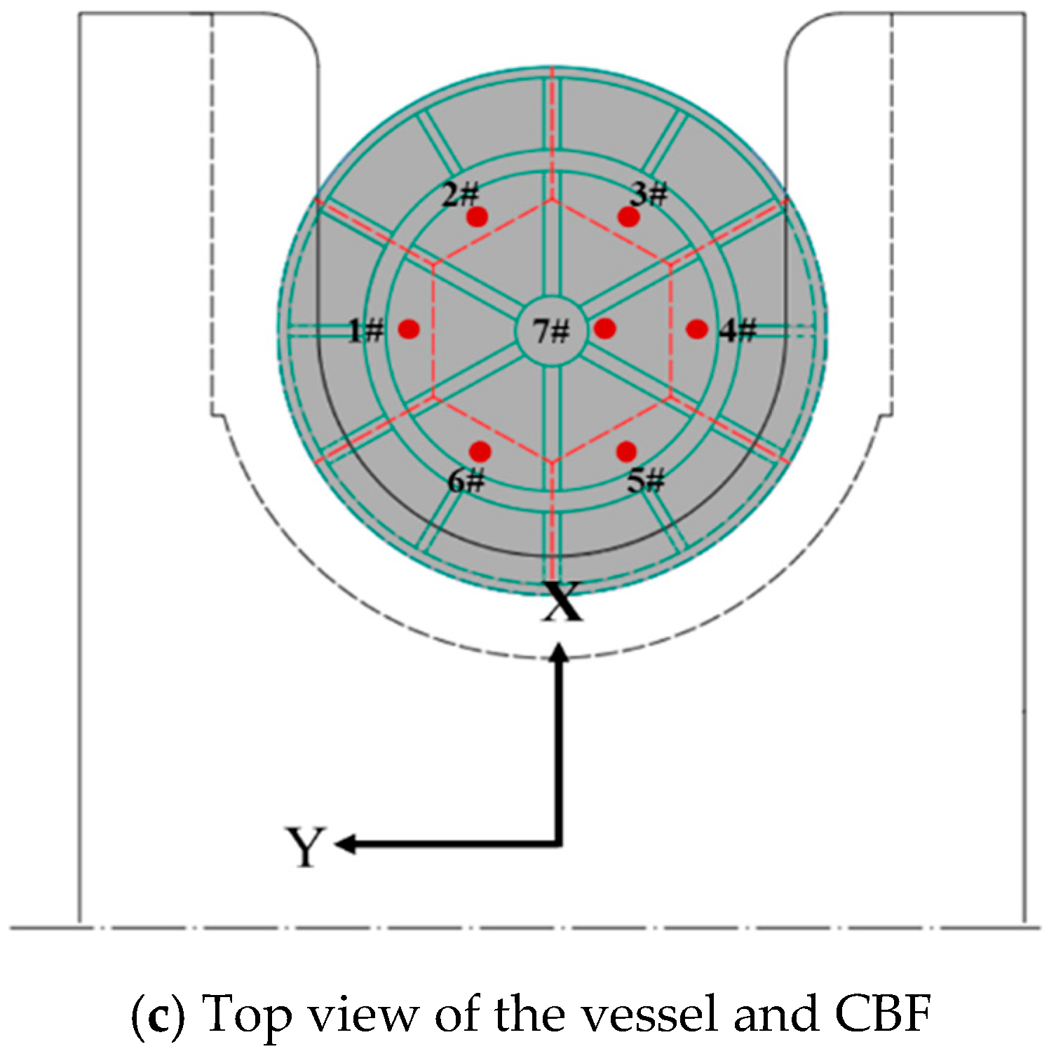
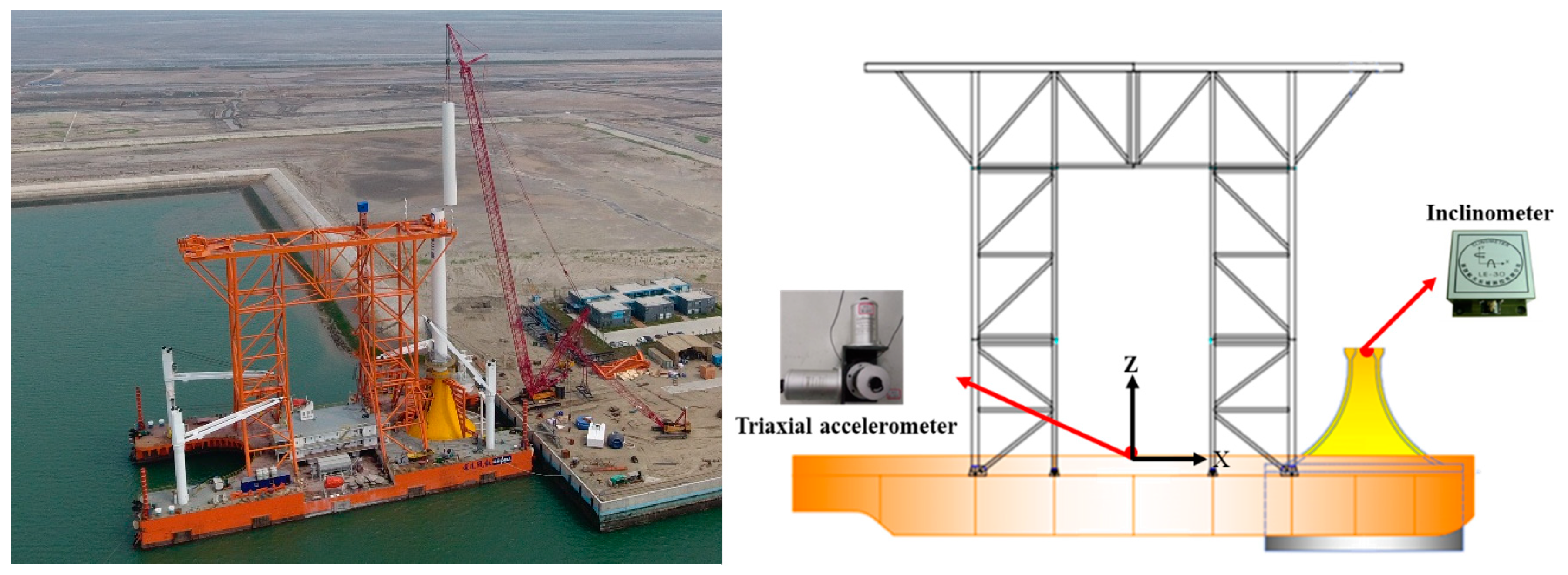
2.2. Description of the Monitoring Equipment and Conditions

As mentioned above, the CBF and OSTIV were closely combined to achieve a synchronous and coordinated movement of the whole structure. In this paper, the assumption has been put forward that the deformation of the structure is small and can be ignored, that is, the structure is equivalent to a rigid body supported on the spring coupled by the compressible air cushion and water cushion. A biaxial inclinometer was installed in the top flange of the CBF to monitor the roll and pitch angles of the structure during transport. A three-way acceleration sensor was positioned on top of the test tower to measure the acceleration on top of the tower during towing. The axes were the same for the accelerometer as for the inclinometer. Seven pressure sensors were installed at the top of seven rooms to monitor their internal air pressures. The net force on the CBF can be obtained as the difference between the buoyancy force and the weight of the CBF. The installed set of sensors is shown in Figure 5, where (a) and (b) are the arrangement of the inclinometer and the acceleration sensor, respectively, and (c) displays the mounting position of seven pressure sensors. In particular, the acceleration sensor was positioned at the midpoint of the vessel deck during the lifting process.
Considering that the towing process lasted for a long time, four typical conditions were selected for analysis. These are listed in Table 2. The speed was obtained directly from the vessel control system. The wave height and wind speed were obtained from meteorological data and observation records during transportation. Conditions 1 and 2 are, respectively, the maximum wave height in beam sea and head sea during transport. For the case of the high wind speeds and wave heights seen in Conditions 3 and 4, the vessel was anchored for shelter and stability in the rougher conditions. As shown in Table 2, the vessel encountered transverse waves under Conditions 1 and 3, and longitudinal waves in working Condition 2. Under Condition 4, the vessel was affected by oblique waves.

3. Results and Interpretation

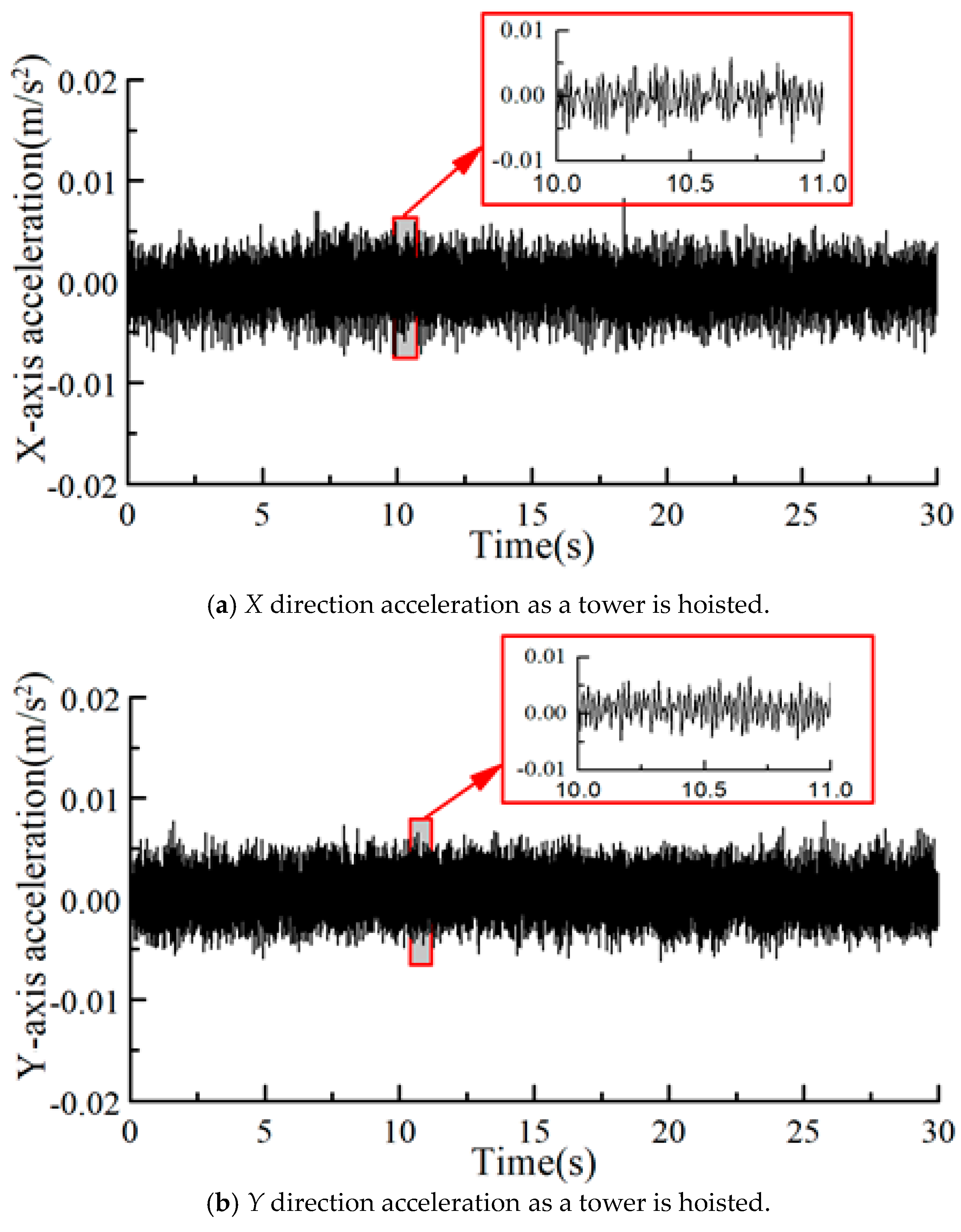
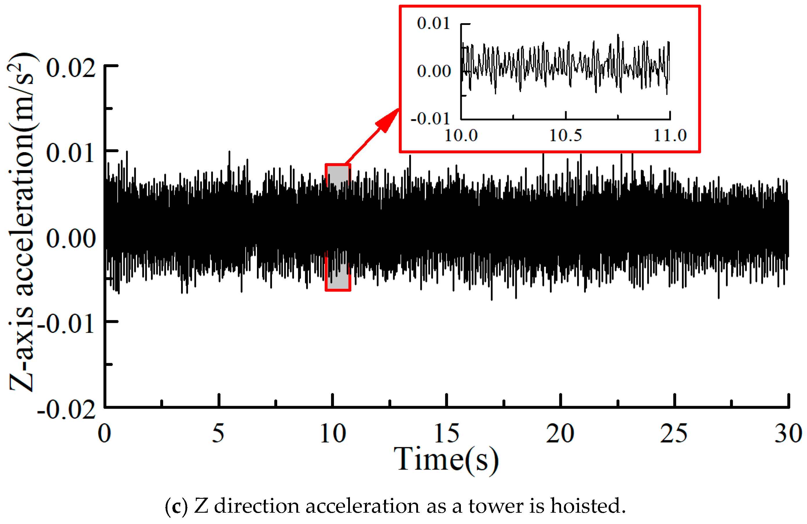
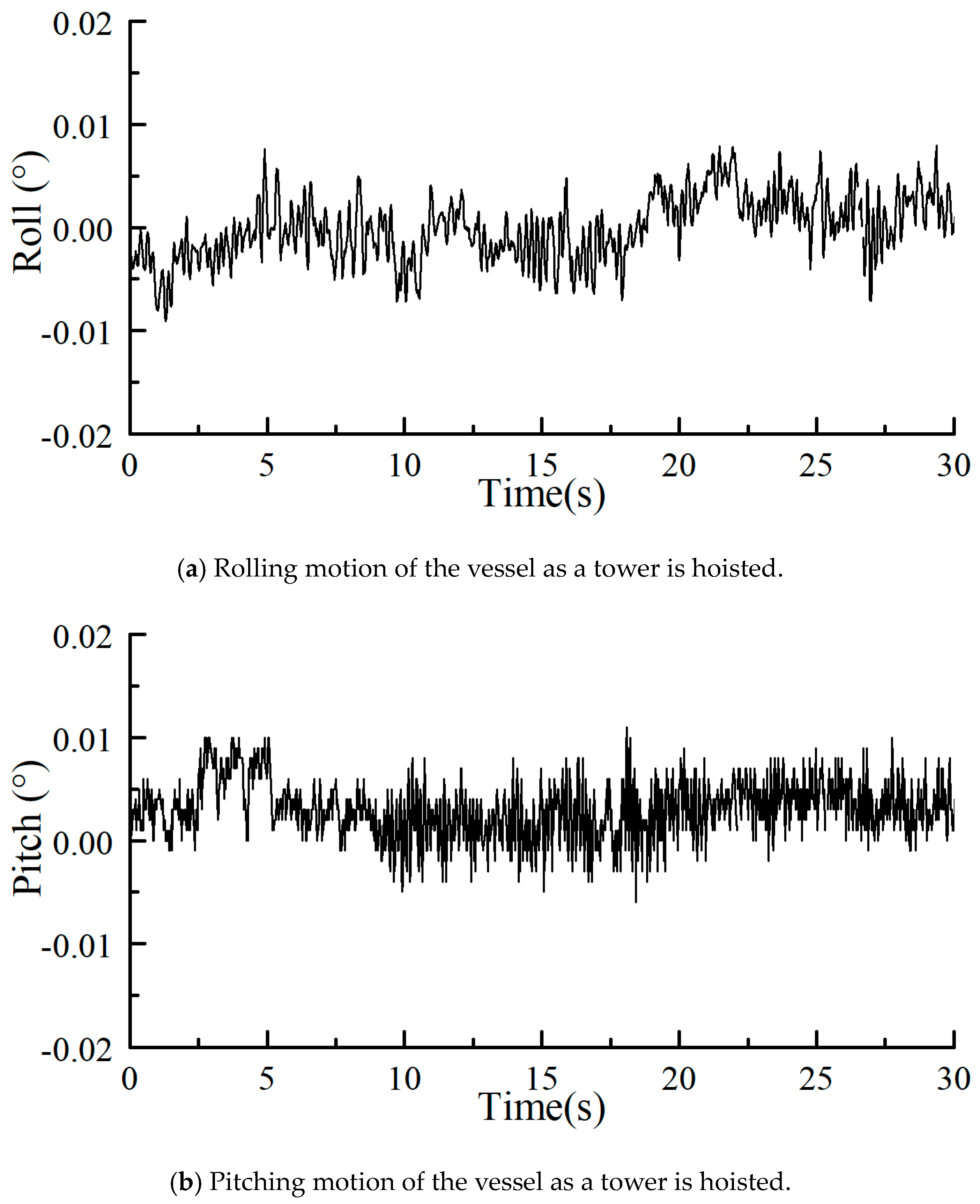
3.1. Motion Characteristics of the Vessel during Hoisting

The onshore process of hoisting and the commissioning tests for wind turbines at dock in an inner harbor is the key process sequence to achieve the one-step installation of CBFs and wind turbines, as shown in Figure 6. During the process of hoisting turbines’ structures on the shore, a CBF is fixed on the vessel, which moves due to the actions of waves and tides, bringing instability to the tower hoisting process. Therefore, as a turbine tower is lifted, a three-way acceleration sensor and a biaxial inclinometer are used to monitor the motion of the vessel. As could be seen from Figure 6, the water in the harbor was very calm. According to the observation, the wave height was always less than 10 cm, so the wave was not measured and statistically calculated during the hoisting process.
Figure 7 and Figure 8 are the 30 s time series for acceleration and the roll and pitch motion before and after the contact between the tower and the CBF. It can be seen from Figure 7 that, as the tower is hoisted, the triaxial acceleration of the vessel was less than 0.01 m/s2, and there is no significant change in the triaxial acceleration over the course of the hoisting process. The roll and pitch angles were much less than 0.02°. Since the wave load is very small and the same mass of a single tower only accounts for 0.41% of the total mass of the structure, the hoisting of the tower did not cause the visible fluctuation of the vessel. In conclusion, the whole structures have good stability and stay in an adequately stable position during hoisting.

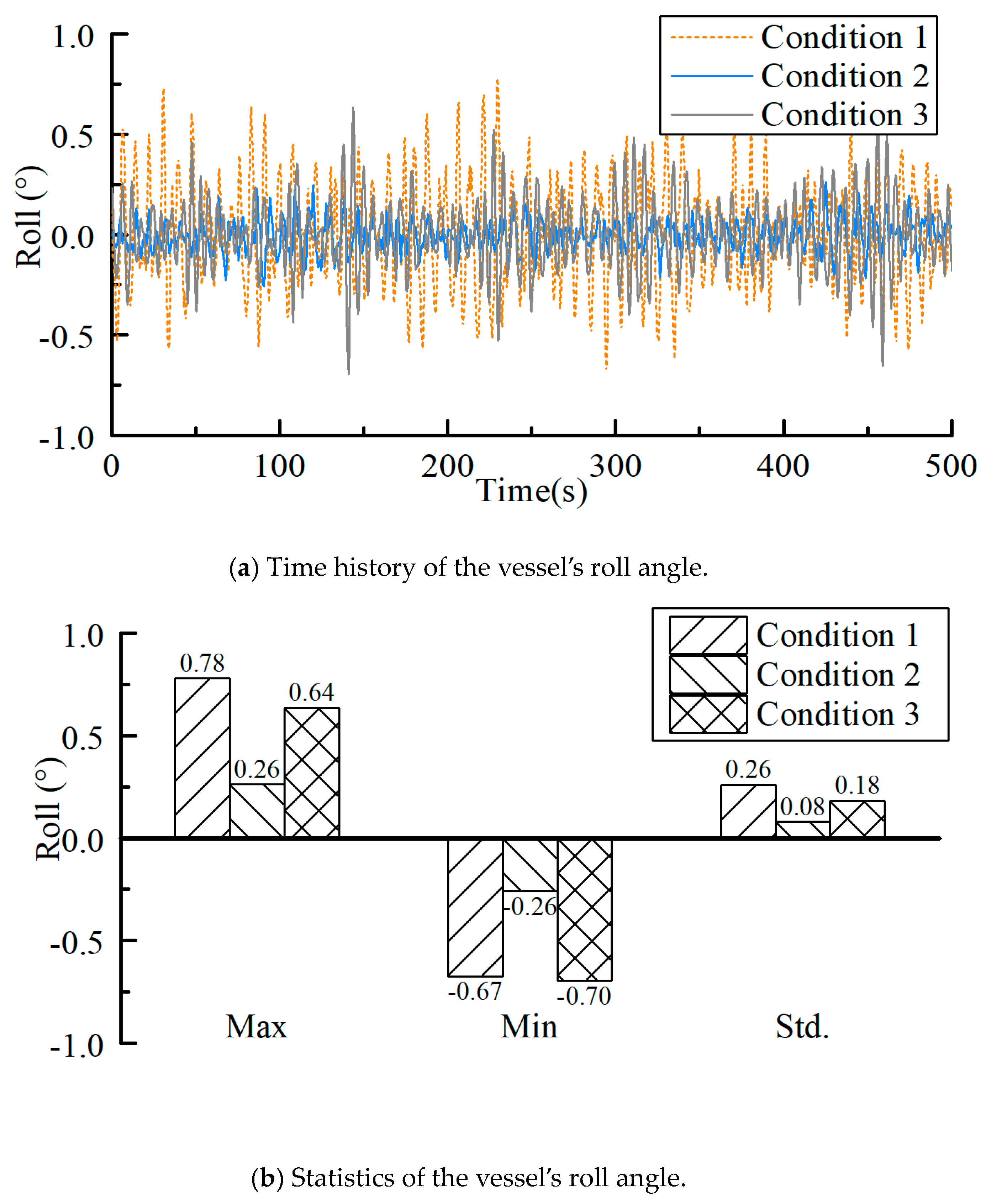
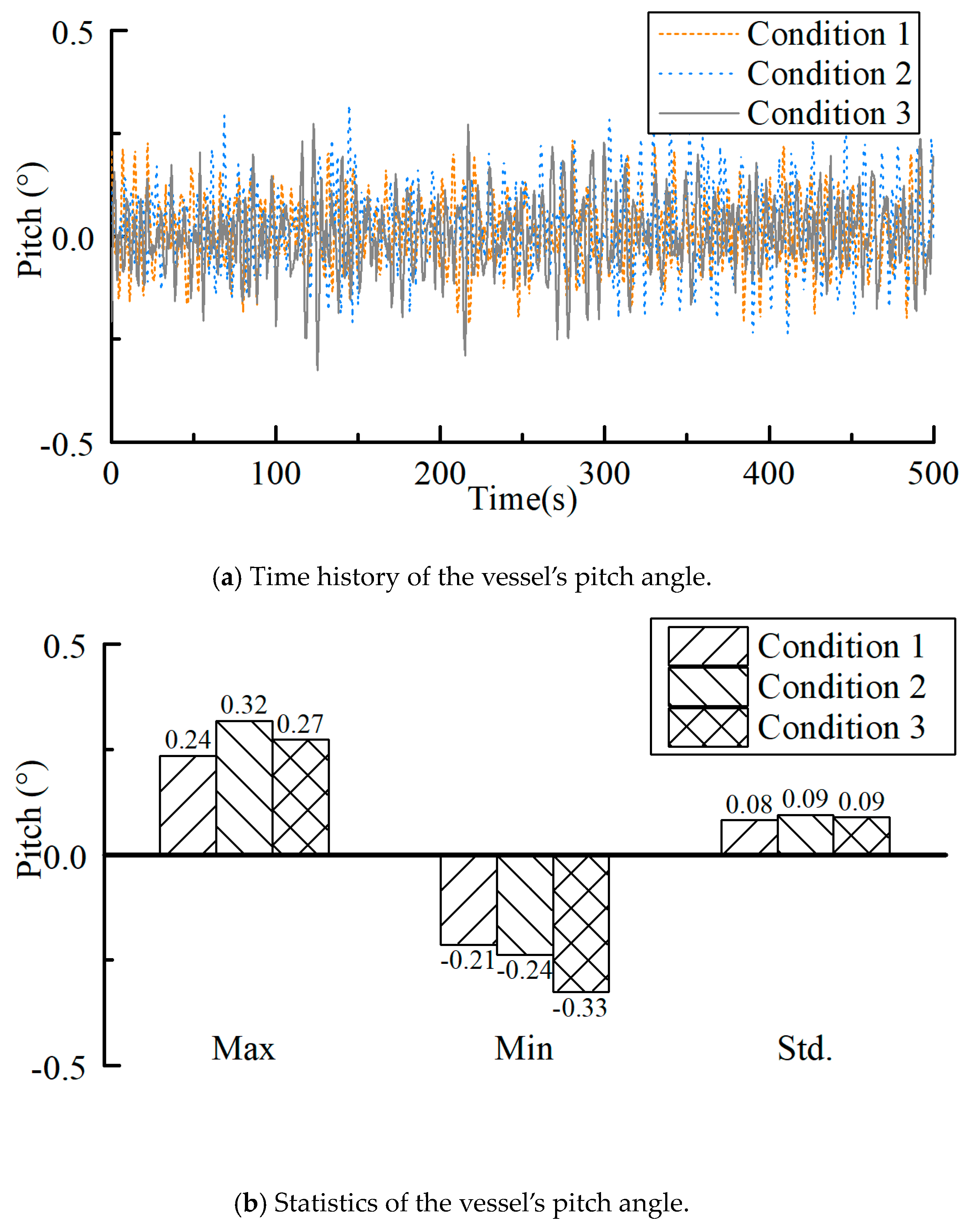
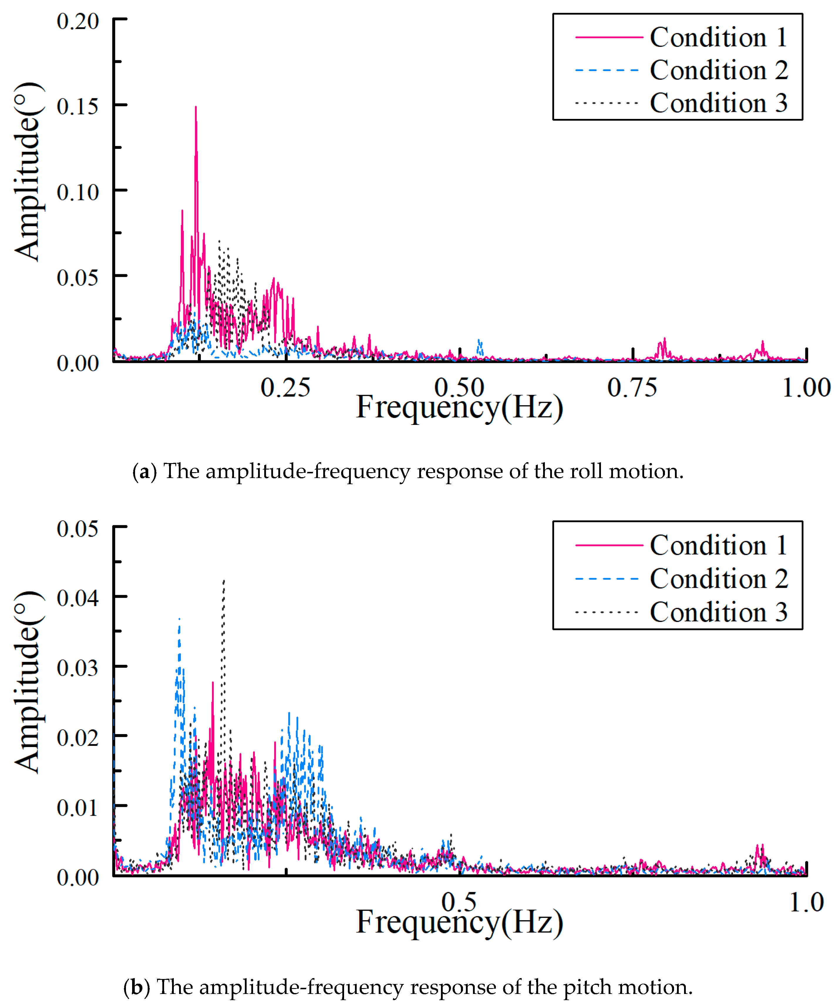
3.2. Roll and Pitch Angles during Towing

The roll and pitch motions of the vessel will lead the fluctuation of the air pressure and compressed air volume inside the bucket. The air in the bucket will leak when the vessel’s roll and pitch angles are too large. Moreover, the CBF bound at the bow and the stern of the vessel rose or fell as a single object due to pitch motion of the vessel during the towing process. That is, the foundation would have a heaving type of motion, which would lead to drastic changes in the buoyancy of the foundation and affect its safety. Figure 9 shows the time history and statistics of the vessel’s roll angle during transport. It can be seen that the roll angle under all working conditions never exceeds 1° and is less than 0.5° in most cases. Time history and statistical values of the pitch angle of the vessel are shown in Figure 10. As can be seen from Figure 10, the pitch of the vessel was always staying within a small range, which was most of the time less than ±0.3°. To ensure no leakage of the air, the vessel’s pitch angle should be less than 4.6° and the roll angle should be less than 2.3°. The results of the monitoring data show that the ship’s motion meets the requirements. The statistics of roll and pitch motions are listed in Table 3. According to this comparison for Conditions 1 and 2, it was shown that wave height has less influence on the pitch of the vessel than on the roll in the case of the same wave height, because the length of the vessel is twice as long as its width, so the pitch stiffness is greater. The results show that the vessel response in roll was larger with the small wave’s Condition 1 than in the larger wave’s Condition 3. This was because the ship was in the state of anchoring in Condition 3, and the anchoring system provided a certain recovery force, which increased the vessel’s rolling stiffness.
Figure 11 shows the amplitude-frequency response of the vessel and the CBF’s roll and pitch motions during transport. As could be seen from Figure 11a, the roll amplitude peaked when the natural rolling frequency of the vessel was 0.12 Hz. Another peak value was at a frequency of 0.23 Hz in Conditions 1 and 3, from which we can infer that this was the dominating wave frequency. The peak values appeared in a range of about 0.16 Hz in Condition 3, which was speculated to be due to a higher wave height and a longer wave period. However, because the vessel was anchored in Condition 3, the rolling motion was less than that of Condition 1. As shown in Figure 11b, the pitch motion natural frequency is 0.09 Hz, meaning that there are several peaks in the amplitude-frequency response curve of pitch around 0.09 Hz. In Condition 2, the vessel encountered head waves, meaning that the pitch motion generated by waves was, relatively speaking, larger than that in other conditions. However, due to the small pitch motion response, the peak value is not prominent in Conditions 1 and 3.

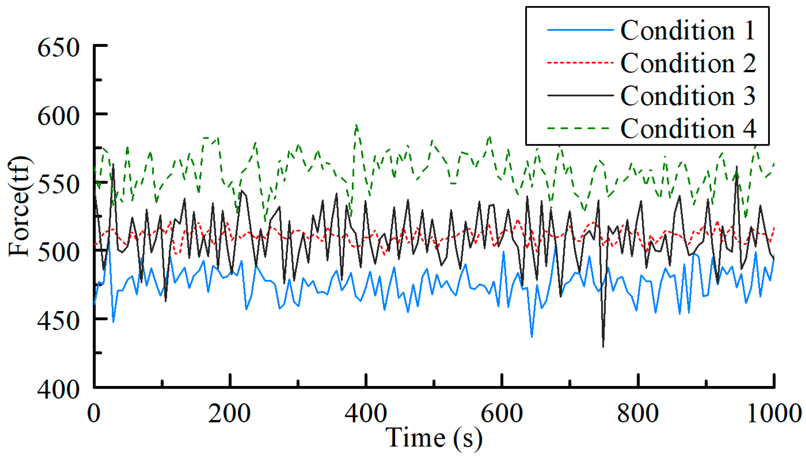
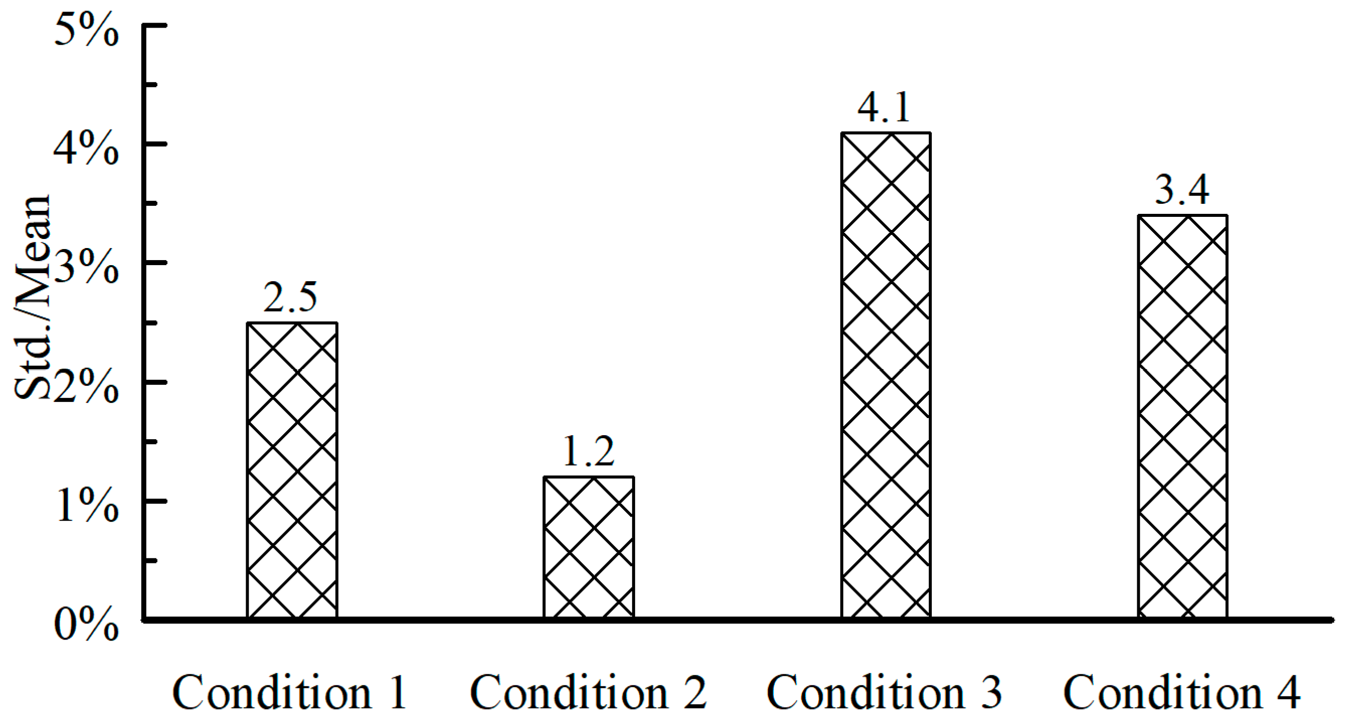
3.3. The Interaction Forces during Transport

Enough compressed air is pumped into the seven compartments of the CBF to generate buoyancy, which not only balances the weight of the CBF but also generates net buoyancy of about 500 tf. The net buoyancy generates pre-pressure between the bottom of the vessel and the top of the beam-plate system, ensuring that the vessel and the CBF will not move in relation to each other. The interacting force (around 500 tf) between the vessel and CBF are generated by the net buoyancy of the bucket. During transport, the fluctuation of interacting forces is mainly caused by the motions of the structure under load and the fluctuation of air pressure in the bucket. Figure 12 shows the time histories of the interacting forces for 4 conditions. It can be clearly seen from Figure 12 that the interacting force was above 400 tf from beginning to end under four conditions, indicating that the CBF and vessel are securely connected and with a large safety reserve under the action of environmentally induced loads.
At the same time, it was necessary to ensure that the fluctuating values of the interacting forces do not have excessive peaks, which could cause damage to the vessel and the turbine’s foundation. Statistics for the interacting forces are shown in Table 4 and Figure 13. It was found that the standard deviation of the interacting force under Condition 1 is twice that seen under Condition 2. The reason is that the vessel’s roll motion in Condition 1 was much larger than that in Condition 2, although the pitch motion response was very close. Contrasting Conditions 3 and 4, the standard deviation did not change significantly when the wave height increased by 1 m. This was because the air pressure inside the bucket was maintained at a high level during Condition 4, and the pressure fluctuation caused by the external load was small. As a result, the change of the interacting force caused by the air pressure in bucket was small.
The nacelle and blades were not loaded for the transport process described in this paper. If the nacelle and blades are loaded, the total weight will increase by 270 t, which is only 10% of the weight of the CBF and wind turbine. Therefore, it can be concluded that the floating behavior of the vessel and CBF will not be significantly affected and the transportation of the whole machine is safe.

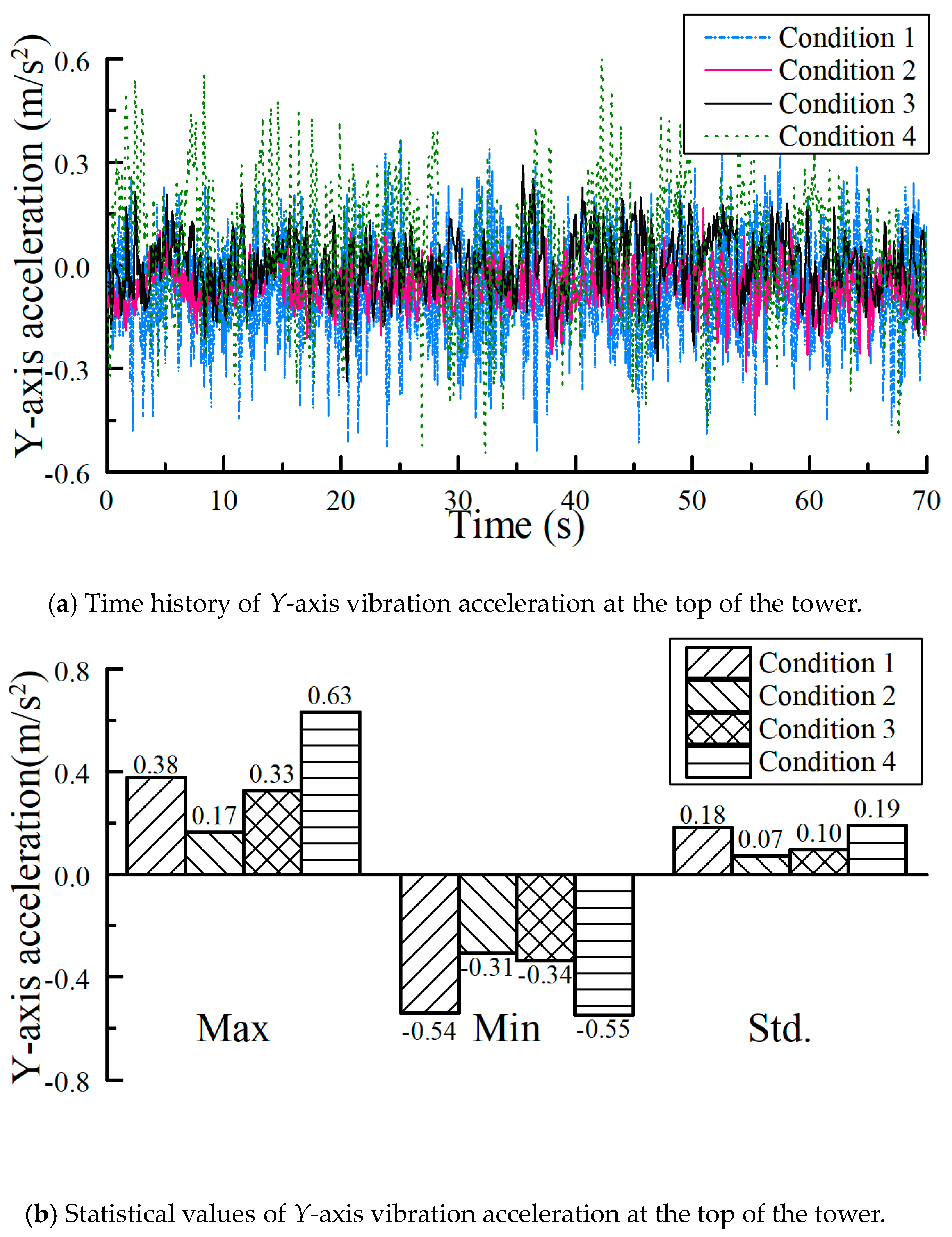
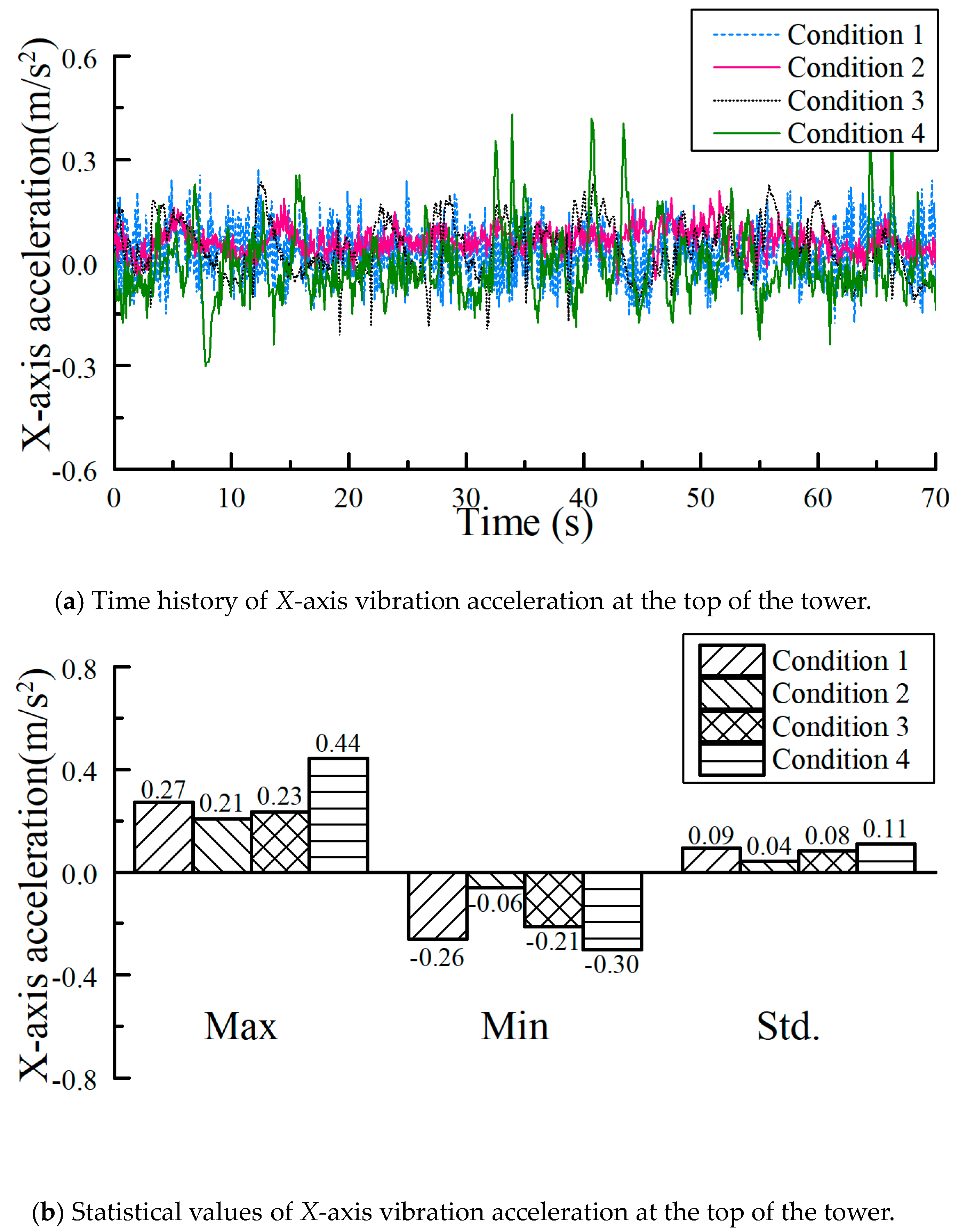
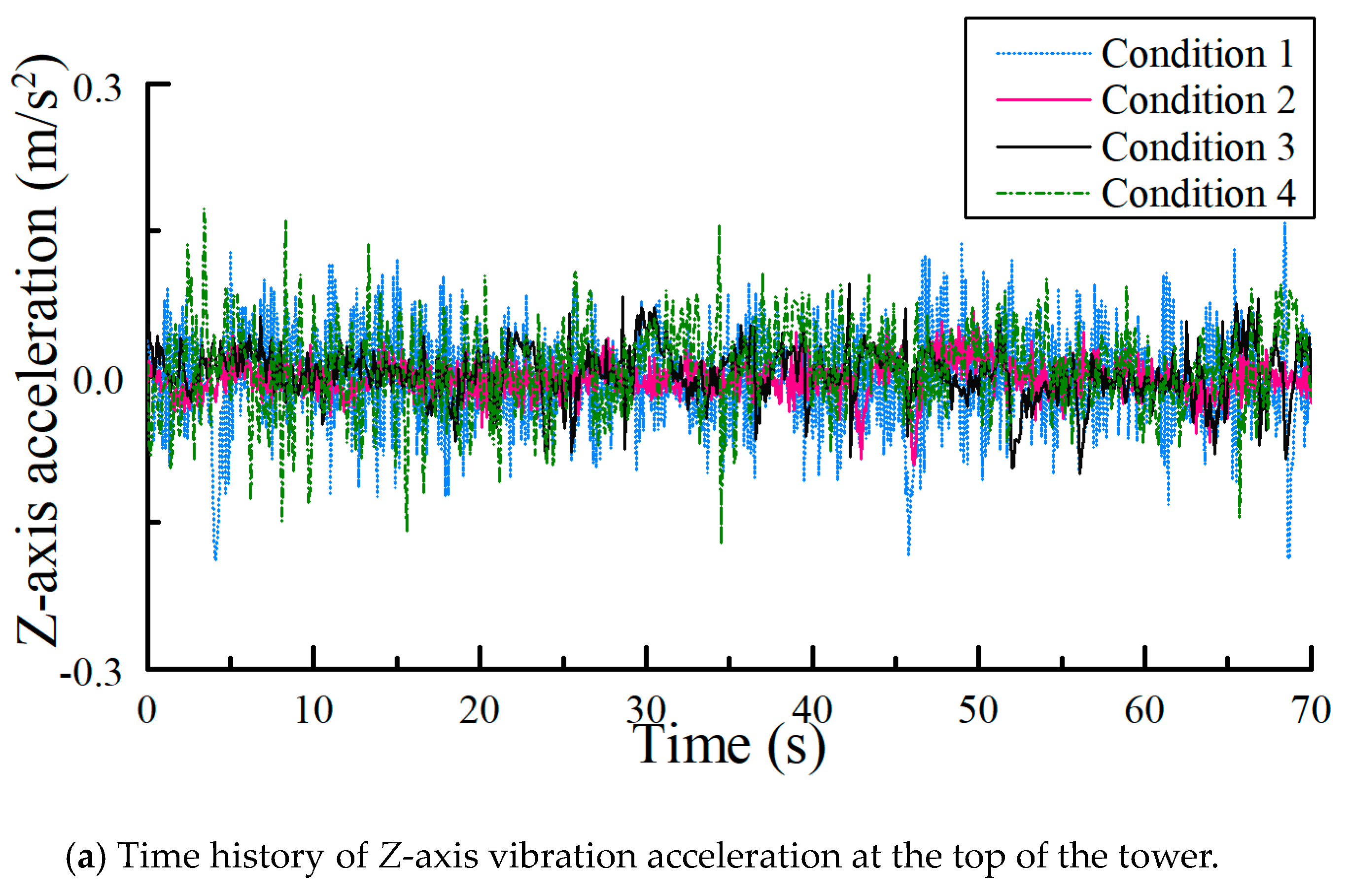
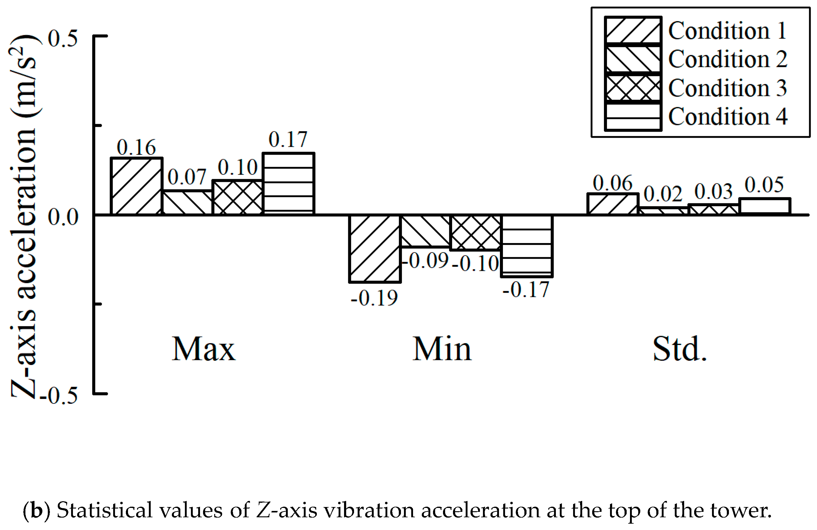
3.4. The Vibration of the Tower during Transport

The time history and statistical values of the three-way vibration at the top of the tower under four conditions are shown in Figure 14, Figure 15 and Figure 16. The maximum values are shown in Table 5. It could clearly be seen that during the transport process (Conditions 1 and 2), the horizontal acceleration values during the whole process were always less than 0.05 g. It can be seen from Figure 14 that the statistical trend of acceleration in the Y-direction is similar to the roll motion, which indicates that the acceleration in the Y-direction is mainly generated by the roll motion of the vessel. Similarly, the acceleration in the X-direction is due to the pitching motion of the ship. The vertical acceleration values were always less than 0.02 g, much less than the limiting values of 0.25 g and 0.2 g. Even with a wind speed of level 8 and a wave height of 3 m, the horizontal acceleration after anchoring is no more than 0.08 g and the vertical acceleration is no more than 0.02 g. The results also showed that the one-step installation method of the CBF and wind turbine can meet the specified limits for tower vibration.

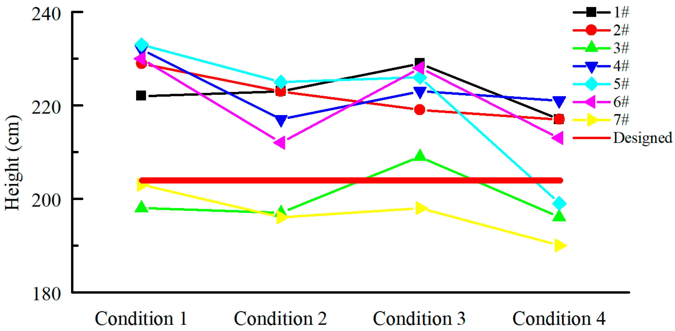
3.5. The liquid Level in the Bucket during Towing

Since the CBF is an air-cushioned structure, it was necessary to ensure that the liquid level in the bucket was high enough so that the air in the bucket would not leak out from the bottom during towing. Radar level gauges was used to measure the height of the liquid level in seven compartments of the bucket, and the measurement results are shown in Figure 17. It can be concluded from the figure that the height of the liquid level was always more than 190 cm, which ensured that the gas in the cylinder would not escape from the bucket. Moreover, the fluctuation of the liquid level can be calculated from the fluctuation of the interaction force with the roll and pitch angles of the vessel, indicating that relatively stable buoyancy can be provided.

4. Conclusions

This paper focused on one of the key technologies for the one-step transportation and installation of CBFs for a turbine wind farm near Xiangshui in China. This is the turbine offshore transport process, which is monitored in real time. By analyzing the measurement results for the response of the entire coupling system, including the roll and pitch angles, the interactive forces between the vessel and the CBF, and the vibration characteristics of the tower and the liquid level in the bucket, the following conclusions can be drawn:
(1)
During the process of lifting the wind tower, the three-way acceleration of the installation ship was always less than 0.01 m/s2, and the roll and pitch angles were less than 0.02°, which means the whole structures have good stability and stay in an adequately stable position during hoisting.
(2)
During the transportation process, the maximum roll and pitch angles of the vessel and CBF were less than 1° and were less than 0.5° in most cases. These small roll and pitch values indicate that the vessel and the CBF have good movement stability and can ensure the safety of the CBF during the transportation process.
(3)
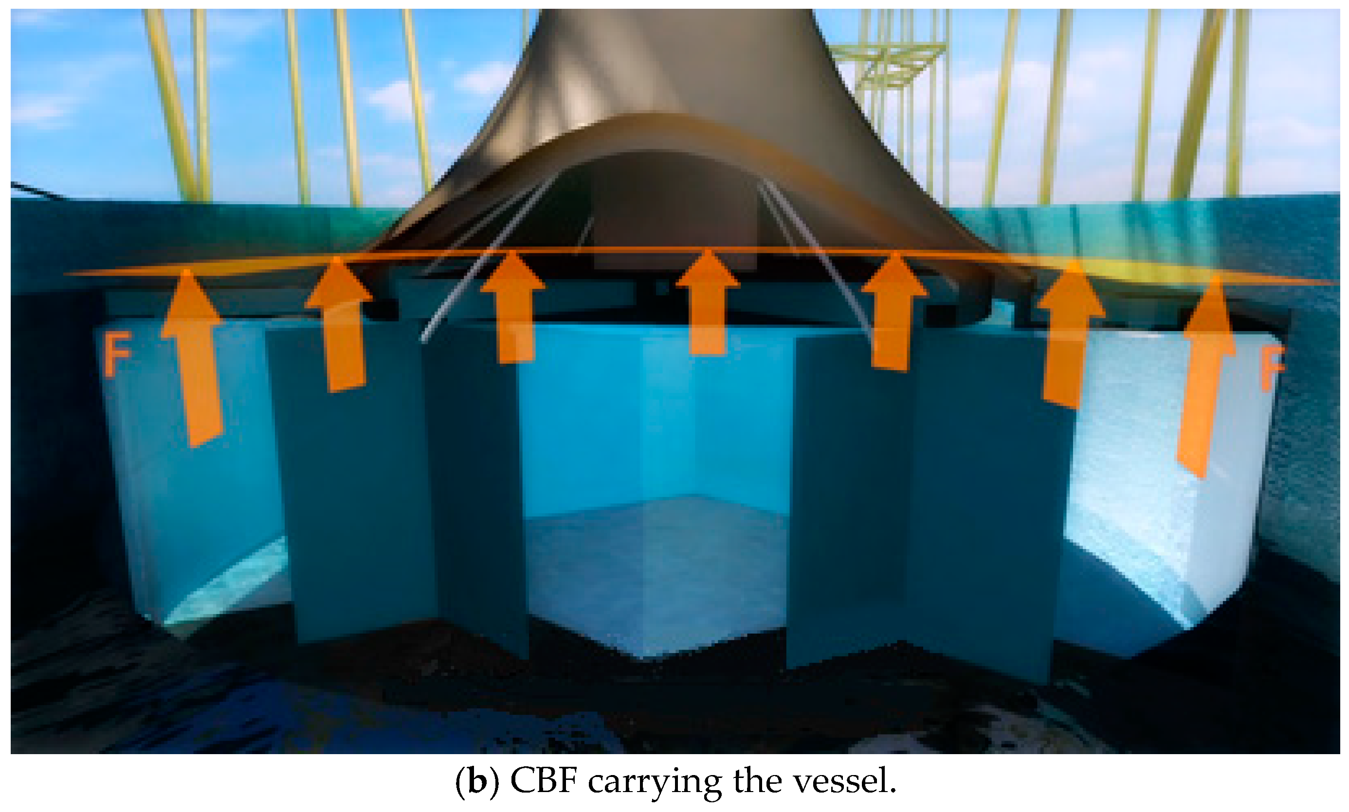
The safety of the aircushion structure of the CBF was verified by an analysis of the measured results for the interaction forces and the height of the liquid level in the bucket.
(4)
The results of the three-way acceleration monitoring on top of the test tower indicate that the wind turbines meet the requirements for the maximum acceleration value limits during transport.

Author Contributions

Conceptualization, H.D. and P.Z.; Methodology, H.D., P.Z. and C.L.; Monitoring, Z.F. and Y.G.; Validation, C.L., P.Z. and H.D.; Formal Analysis, Z.F.; Writing-Original Draft Preparation, Z.F. and P.Z.; Writing-Review & Editing, Z.F. and P.Z.; Supervision, H.D. and P.Z; Project administration, H.D. and P.Z; Funding acquisition, H.D., C.L. and Y.G. All authors have read and agreed to the published version of the manuscript.

Funding

This research was funded by the National Natural Science Foundation of China (Grant Nos. 51679163 & 51909188) and Tianjin Municipal Natural Science Foundation (Grant No. 18JCYBJC22800).

Conflicts of Interest

The authors declare no conflict of interest.

References

  1. Global Wind Energy Council (GWEC). Global Wind Report; GWEC: Brussels, Belgium, 2018. [Google Scholar]
  2. Zhang, P.; Ding, H.; Le, C.; Huang, X. Motion analysis on integrated transportation technique for offshore wind turbines. J. Renew. Sustain. Energy 2013, 5, 53117. [Google Scholar] [CrossRef]
  3. Fu, D.; Gaudin, C.; Tian, C.; Bienen, B.; Cassidy, M. Effects of preloading with consolidation on undrained bearing capacity of skirted circular footings. Géotechnique 2015, 65, 231–246. [Google Scholar] [CrossRef]
  4. Shi, W.; Park, H.; Chung, C.; Baek, J.; Kim, Y.; Kim, C. Load analysis and comparison of different jacket foundations. Renew. Energy 2013, 54, 201–210. [Google Scholar] [CrossRef]
  5. Uraz, E. Offshore Wind Turbine Transportation & Installation Analyses. Planning Optimal Marine Operations for Offshore Wind Projects, Praca Magisterska; Gotland University: Visby, Sweden, 2011. [Google Scholar]
  6. Wang, X.; Zeng, X.; Li, X.; Li, J. Investigation on offshore wind turbine with an innovative hybrid monopile foundation: An experimental based study. Renew. Energy 2019, 132, 129–141. [Google Scholar] [CrossRef]
  7. Fu, D.; Zhang, Y.; Yan, Y.; Jostad, H.P. Effects of tension gap on the holding capacity of suction anchors. Mar. Struct. 2020, 69, 102679. [Google Scholar] [CrossRef]
  8. Zhang, P.; Ding, H.; Le, C. Model tests on tilt adjustment techniques for a mooring dolphin platform with three suction caisson foundations in clay. Ocean Eng. 2013, 73, 96–105. [Google Scholar] [CrossRef]
  9. Wang, X.; Zeng, X.; Li, J. Vertical performance of suction bucket foundation for offshore wind turbines in sand. Ocean Eng. 2019, 180, 40–48. [Google Scholar] [CrossRef] [Green Version]
  10. Ding, H.; Zhao, X.; Le, C.; Zhang, P.; Min, Q. Towing Motion Characteristics of Composite Bucket Foundation for Offshore Wind Turbines. Energies 2019, 12, 3767. [Google Scholar] [CrossRef] [Green Version]
  11. Ding, H.; Liu, Y.; Zhang, P.; Le, C. Model tests on the bearing capacity of wide-shallow composite bucket foundations for offshore wind turbines in clay. Ocean Eng. 2015, 103, 114–122. [Google Scholar] [CrossRef]
  12. Ding, H.; Liu, Y.; Zhang, P. Negative pressure consolidation of silt inside bucket foundation. Trans. Tianjin Univ. 2015, 21, 333–340. [Google Scholar] [CrossRef]
  13. Zhang, P.; Liang, D.; Ding, H.; Le, C.; Zhao, X. Floating State of a One-Step Integrated Transportation Vessel with Two Composite Bucket Foundations and Offshore Wind Turbines. J. Mar. Sci. Eng. 2019, 7, 263. [Google Scholar] [CrossRef] [Green Version]
  14. Zhang, P.; Hu, R.; Ding, H.; Guo, Y.; Xiong, K. Comparative analysis of seepage field characteristics in bucket foundation with and without compartments. Ocean Eng. 2017, 143, 34–49. [Google Scholar] [CrossRef]
  15. Zhang, P.; Ding, H.; Le, C. Seismic response of large-scale prestressed concrete bucket foundation for offshore wind turbines. J. Renew. Sustain. Energy 2014, 6, 13127. [Google Scholar] [CrossRef]
  16. Ding, H.; Lian, J.; Li, A.; Zhang, P. The Invention Relates to Floating Transportation Method of Offshore Wind Turbine. CN 1,029,269,49A, 13 February 2013. [Google Scholar]
  17. He, S.; Zhang, P.; Ding, H. Study on the Bearing Mode and Force Transfer Path of Composite Bucket Foundations. Energies 2017, 10, 1041. [Google Scholar] [CrossRef] [Green Version]
  18. Ding, H.; Zhang, P.; Lian, J. The Invention Relates to a Bucket Foundation Sinking Method for Water Displacement of Air. CN 1,017,367,48A, 16 June 2010. [Google Scholar]
  19. Zhang, P.; Guo, Y.; Liu, Y.; Ding, H. Experimental study on installation of hybrid bucket foundations for offshore wind turbines in silty clay. Ocean Eng. 2016, 114, 87–100. [Google Scholar] [CrossRef]
  20. Ding, H.; Lian, J.; Li, A.; Zhang, P. One-step-installation of offshore wind turbine on large-scale bucket-top-bearing bucket foundation. Trans. Tianjin Univ. 2013, 19, 188–194. [Google Scholar] [CrossRef]
  21. Zhang, P.; Han, Y.; Ding, H.; Zhang, S. Field experiments on wet tows of an integrated transportation and installation vessel with two bucket foundations for offshore wind turbines. Ocean Eng. 2015, 108, 769–777. [Google Scholar] [CrossRef]
  22. Pinkster, J.A.; Fauzi, A. Motions and drift forces of air-supported structures in waves. In Proceedings of the 5th WEGEMT Workshop Non-Linear Wave Action on Structures and Ships, Toulon-Var, France, 4–8 July 1998. [Google Scholar]
  23. Pinkster, J.A. The behavior of large air cushion supported structures in waves. Proceeding on Hydroelasticity in Marine Technology. Hydroelasticity 1998, 98, 497–506. [Google Scholar]
  24. Tabeta, S.; Pinkster, J.A. Model Experiments on Barge Type Floating Structures Supported by Air Cushions; TUDelft, Faculty of Marine Technology, Ship Hydromechanics Laboratory Report 1125; The University of Yokohama: Yokohama, Japan, 1998. [Google Scholar]
  25. Malenica, S.; Zalar, M. An alternative method for linear hydrodynamics of air cushion supported floating bodies. In Proceedings of the 15th International Workshop on Water Waves and Floating Bodies, Caesarea, Israel, 17 February–1 March 2000; pp. 1–4. [Google Scholar]
  26. Thiagarajan, K.P. An effective scaling device for model testing of air cushion vehicles in a Laboratory. In Proceedings of the 25th Symposium on Naval Hydrodynamics, St. John’s, NL, Canada, 8–13 August 2004. [Google Scholar]
  27. Thiagarajan, K.P.; Morris-Thomas, M.T.; Spargo, A. Heave and pitch response of an offshore platform with air cushion support in shallow water. In Proceedings of the ASME 2004 23rd International Conference on Offshore Mechanics and Arctic Engineering, Vancouver, BC, Canada, 20–25 June 2004; pp. 817–823. [Google Scholar]
  28. Chenu, B.; Morris-Thomas, M.T.; Thiagarajan, K.P. Some hydrodynamic characteristics of an air-cushion supported concrete gravity structure. In Proceedings of the 15th Australasian Fluid Mechanics Conference, Sydney, Australia, 13–17 December 2004. [Google Scholar]
  29. Ikoma, T.; Masuda, K.; Maeda, H.; Rheem, C.K. Hydroelastic behavior of air-supported flexible floating structures. In Proceedings of the ASME 2002 21st International Conference on Offshore Mechanics and Arctic Engineering, Oslo, Norway, 23–28 June 2002; pp. 745–752. [Google Scholar]
  30. Ikoma, T.; Masuda, K.; Maeda, H.; Rheem, C.K. A prediction method of hydroelastic motion of aircushion type floating structures considering with draft effect into hydrodynamic forces. In Proceedings of the ASME 2008 27th International Conference on Offshore Mechanics and Arctic Engineering, Estoril, Portugal, 15–20 June 2008; pp. 421–429. [Google Scholar]
  31. Ikoma, T.; Masuda, K.; Rheem, C.-K.; Maeda, H. Response Reduction of Motion and Steady Wave Drifting Forces of Floating Bodies Supported by Aircushions in Regular Waves: The 2nd Report—Response Characteristics in Oblique Waves. In Proceedings of the ASME 2007 26st International Conference on Offshore Mechanics and Arctic Engineering, San Diego, CA, USA, 10–15 June 2007; pp. 3–9. [Google Scholar]
  32. Zhang, P.; Ding, H.; Le, C. Hydrodynamic motion of a large prestressed concrete bucket foundation for offshore wind turbines. J. Renew. Sustain. Energy 2013, 5, 63126. [Google Scholar] [CrossRef]
  33. Liu, X.; Zhang, P.; Zhao, M.; Ding, H.; Le, C. Influencing Factors of Motion Responses for Large-Diameter Tripod Bucket Foundation. Appl. Sci. 2019, 9, 4957. [Google Scholar] [CrossRef] [Green Version]
  34. Liu, X.; Zhang, P.; Zhao, M.; Ding, H.; Le, C. Air-Floating Characteristics of Large-Diameter Multi-Bucket Foundation for Offshore Wind Turbines. Energies 2019, 12, 4108. [Google Scholar] [CrossRef] [Green Version]
Figure 1. The composite bucket foundation (CBF).
Energies 13 00882 g001
Figure 2. Construction process of the CBF.
Energies 13 00882 g002
Figure 3. The connection method between the CBF and the vessel.
Energies 13 00882 g003aEnergies 13 00882 g003b
Figure 4. The prototype used for one-step transport.
Energies 13 00882 g004
Figure 5. Installed array of sensors.
Energies 13 00882 g005aEnergies 13 00882 g005b
Figure 6. Hoisting process of tower at dock.
Energies 13 00882 g006
Figure 7. The three-axis acceleration data for the vessel’s motion as a tower is hoisted.
Energies 13 00882 g007aEnergies 13 00882 g007b
Figure 8. The roll and pitch angles of the vessel as a tower is hoisted.
Energies 13 00882 g008
Figure 9. The time history and statistics of the vessel’s roll angle.
Energies 13 00882 g009
Figure 10. The time history and statistics of the vessel’s pitch angle.
Energies 13 00882 g010
Figure 11. The amplitude-frequency response of the roll and pitch.
Energies 13 00882 g011
Figure 12. The interacting forces during transport process.
Energies 13 00882 g012
Figure 13. Statistics of the interacting forces.
Energies 13 00882 g013
Figure 14. Y-axis vibration acceleration at the top of the tower.
Energies 13 00882 g014
Figure 15. X-axis vibration acceleration at the top of the tower.
Energies 13 00882 g015
Figure 16. Z-axis vibration acceleration at the top of the tower.
Energies 13 00882 g016aEnergies 13 00882 g016b
Figure 17. The liquid level height.
Energies 13 00882 g017
Table 1. The parameters of the overall structure.
PropertyValuesPropertyValues
Molded Length (m)103Bucket diameter (m)30
Molded Breadth (m)51Bucket height (m)12
Molded Depth (m)9Transition height (m)20
Design Draught (m)6Tower height (m)78.5
Tonnage (t)−16,900Tower mass (t)207.0
Upper groove diameter (m)25Total mass (t)−2700.0
Lower groove diameter (m)37Natural period of roll (s)8.5
Height of truss (m)62Natural period of pitch (s)11.0
Natural period of heave (s)6.7
Table 2. Four typical conditions.
ConditionSpeed (knot)Wind Speed (Beaufort Scale)Average Wave Height (m)Wave Heading
Condition 14.941.5Beam sea
Condition 23.841.2Head sea
Condition 3Anchored82.0Beam sea
Condition 4Anchored83.0Diagonal
Table 3. Statistics of roll and pitch motions.
ConditionMax (°)Min (°)Std. (°)
RollPitchRollPitchRollPitch
Condition 10.780.23−0.57−0.210.280.08
Condition 20.250.32−0.26−0.210.080.08
Condition 30.640.27−0.70−0.330.180.08
Table 4. Statistics of interacting forces.
ConditionMax (tf)Min (tf)Mean (tf)Std. (tf)Std./Mean
Condition 1510430475122.5%
Condition 252549050961.2%
Condition 3600430517214.1%
Condition 4600500556193.4%
Table 5. The maximum values of the vibration acceleration of the tower.
ConditionHorizontal AccelerationHorizontal LimitingMax/
Limiting
Vertical AccelerationVertical LimitingMax/
Limiting
Condition 10.047 g0.25 g18.8%0.019 g0.15 g9.5%
Condition 20.025 g10.0%0.009 g4.5%
Condition 30.036 g14.4%0.010 g5.0%
Condition 40.072 g28.8%0.017 g8.5%

