Article

Real-time Energy Management Strategy for Oil-Electric-Liquid Hybrid System based on Lowest Instantaneous Energy Consumption Cost

1
State Key Laboratory of Mechanical Transmission, Chongqing University, Chongqing 400044, China
2
School of Automotive Engineering, Chongqing University, Chongqing 400044, China
*
Author to whom correspondence should be addressed.
Energies 2020, 13(4), 784; https://doi.org/10.3390/en13040784
Submission received: 10 January 2020 / Revised: 4 February 2020 / Accepted: 8 February 2020 / Published: 11 February 2020
(This article belongs to the Special Issue Energy Storage Systems for Electric Vehicles)

Abstract

:
For the oil–electric–hydraulic hybrid power system, a logic threshold energy management strategy based on the optimal working curve is proposed, and the optimal working curve in each mode is determined. A genetic algorithm is used to determine the optimal parameters. For driving conditions, a real-time energy management strategy based on the lowest instantaneous energy cost is proposed. For braking conditions and subject to the European Commission for Europe (ECE) regulations, a braking force distribution strategy based on hydraulic pumps/motors and supplemented by motors is proposed. A global optimization energy management strategy is used to evaluate the strategy. Simulation results show that the strategy can achieve the expected control target and save about 32.14% compared with the fuel consumption cost of the original model 100 km 8 L. Under the New European Driving Cycle (NEDC) working conditions, the energy-saving effect of this strategy is close to that of the global optimization energy management strategy and has obvious cost advantages. The system design and control strategy are validated.

Graphical Abstract

1. Introduction

With the rise and boom of the automobile industry, the number of automobiles has been increasing, but the related problem of environmental pollution has also been growing. At present, pure electric vehicles are considered to be the cleanest automobiles, but their core technologies, such as motors and power batteries, are difficult to make great breakthrough in a short period of time, which has severely restricted their development. On the other hand, hybrid electric vehicles do not have such problems and are thus gradually being favored by more people. The main problem that needs to be solved in hybrid electric vehicles is determining how to make a reasonable allocation among the power sources under the premise that the demand torque is known. At present, the energy management strategy for hybrid electric vehicles can be roughly divided into a rule-based energy management strategy, instantaneous optimization of energy management strategies, and global optimization of energy management strategies.
Zhou et al. proposed a rule-based energy management strategy that uses dynamic programming (DP) to select control parameters. The fuel consumption per 100 km of the strategy is 12.7 L, which is very close to the global optimal value of 12.4 L [1]. Li et al. on the other hand, proposed a logic threshold strategy optimized via the pseudospectral method, which achieves the goal of reducing battery energy loss by making supercapacitors perform better with a high specific power performance [2]. Whereas Qin et al. proposed an energy management control strategy based on working condition identification, which reduced fuel consumption by 12.77% compared with that of the strategy without working condition identification [3]. Meanwhile, Yin et al. proposed a dual-planetary hybrid electric vehicle as an object of engine torque control. This strategy can optimize the engine operating point while keeping the final battery state of charge (SOC) value within a reasonable range [4]. Although this type of energy management strategy has a simple structure and strong practicability, its advantages and disadvantages are easily affected by the experience of engineering personnel and the working conditions are poor.
For the instantaneous optimization of energy management strategy, Jiao et al. proposed an adaptive equivalent fuel consumption minimum strategy (A-ECMS), which obtains the equivalent factor under current driving conditions based on the equivalent factor map in energy distribution. The fuel consumption is minimized throughout the driving route, and the battery state of charge (SOC) is kept within a reasonable range [5]. On the other hand, Zhang et al. proposed an energy management strategy based on the minimum equivalent fuel consumption. Compared with the rule-based energy management strategy, it has a significant improvement in terms of fuel economy [6]. Meanwhile, Wang et al. proposed an energy control strategy that allows both the engine and the motor to operate in an efficient region to improve fuel economy [7]. Compared with the globally optimized energy management strategy, this strategy has a small amount of calculation and fast speed, but can only achieve instantaneous optimization.
For the global optimization energy management strategy, Xiang Zhu proposed a DP-based energy management strategy. Through online simulation, the solution of the multi-neural network model is determined to be close to the optimal solution obtained by the global optimization algorithm, and the real-time application of dynamic programming is greatly improved [8]. Meanwhile, Wang et al. considered the discrete solutions of related variables and the boundary problems of feasible domains when solving the optimal control problem of hybrid electric vehicle, and systematically studied the relationship between the optimization accuracy and the computational complexity of the dynamic programming algorithm. Compared with that of the traditional control strategy, the fuel economy based on the dynamic planning control strategy increased by about 20% [9]. Although this strategy can achieve global optimization, it needs to obtain the entire driving conditions in advance, and the amount of calculation is large, which is difficult to apply to real vehicles.
In this article, Firstly, the oil–electric–hydraulic system requires one to install a hydraulic energy storage system on the rear axle of the existing oil-electric hybrid vehicle structure, which is proposed in this article and uses a timely four-wheel-drive structure with independent driving of the front and rear axles. Secondly, based on this structure, this study focuses on a steady-state energy management strategy in the driving and braking process, proposes a logic threshold energy management strategy based on the optimal working curve, and selects the relevant threshold according to the steady-state efficiency characteristic curve of the key components. The genetic algorithm is used to jointly optimize the powertrain parameters and logic threshold energy management strategy parameters. Thirdly, for the driving mode, considering that this article mainly focuses on the fuel economy of the entire vehicle, and in the logic threshold energy management strategy, the setting of the threshold value is susceptible to expert experience, the working conditions are poor, the global optimization energy management strategy has a large amount of calculation, the driving conditions need to be known, and practical problems, a real-time energy management strategy based on the lowest energy consumption cost is proposed, whereas for the braking mode, based on the traditional four-wheel vehicle braking force distribution strategy, a braking-force allocation strategy based on the highest energy recovery is proposed. Furthermore, a global optimization energy management strategy based on dynamic programming is used as the basis for evaluating the advantages and disadvantages of other strategies. Finally, the stateflow-based control strategy model is implemented into the forward simulation model to verify the effectiveness of the strategy, and the two strategies are simulated and compared.

2. Oil–Electric–Liquid Hybrid Power System Structure

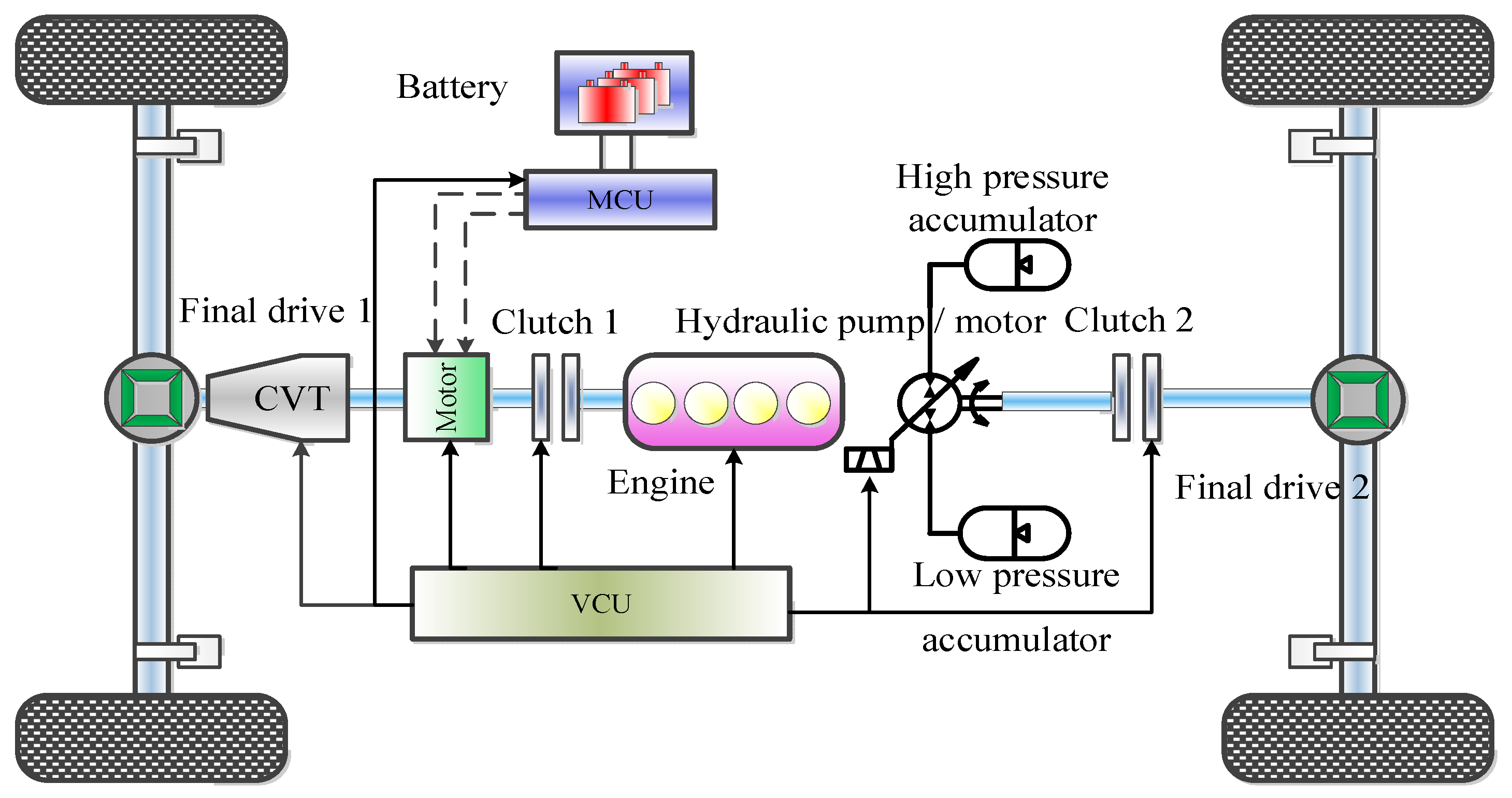
Unlike a pure electric vehicle, an oil–electric hybrid electric vehicle retains the engine and reduces the power of the battery. Although the vehicle’s range is increased, the disadvantage of a reduced energy recovery rate is ignored. Under the same conditions, although the accumulator has a low energy density, it also has a high power density, which not only can quickly recover and release energy, but also has higher energy efficiency and can provide greater auxiliary power for the vehicle. If the characteristics of the high energy density of the storage battery and high power density of the accumulator are combined, not only can the vehicle’s cruising range be extended, but the energy recovery rate can also be improved. Therefore, the traditional configuration is equipped with a motor and an external battery pack on the front axle, and a hydraulic energy storage system on the rear axle. In addition, continuously variable transmission (CVT) can not only adjust the operating point of the engine and motor, save fuel consumption, but also improve the ride and stability of the vehicle. Therefore, this article decided to use CVT transmission. As shown in Figure 1, the new setup is composed mainly of an integrated starter generator (ISG) motor, high-pressure accumulator, low-pressure accumulator, hydraulic pump/motor, battery, and continuously variable transmission (CVT). There are clutches at the connection between the engine and the motor, the hydraulic pump/motor, and the rear axle main reducer. The clutch status of the front and rear axles can be controlled to make the vehicle work in different modes. The vehicle working mode is outlined in Table 1.
Similar to for a traditional automobile, the maximum demand power of an oil–electric hybrid electric vehicle is also determined according to the vehicle dynamics index [10]. This study uses the vehicle’s basic parameters and dynamic indicators of the original model. Based on the vehicle parameters and different driving conditions, the maximum required power of the vehicle can be calculated. From these calculations, the total power of the initial power source is determined to be 120 kW.
In addition, the theoretical calculation method and the comprehensive analysis method based on the cycle condition are used to match the parameters of each key component. The matching results are listed in Table 2.

3. Joint Optimization of Energy Management Strategy and Power System Component Parameters

3.1. Logic Threshold Energy Management Strategy based on Optimal Working Curve

This study is based on the gasoline engine’s universal characteristic curve, and the research object is the rechargeable oil–electric–hydraulic hybrid vehicle. P emin_eco and P emax_eco are used as the logic threshold parameters for charge-sustaining (CS) stage engine operation to optimize the working area of the engine. ( P emin_eco ,   P emax_eco ) = ( 9   kW , 57   kW ) is initially selected, and based on the battery SOC model, the battery SOC = 0.3 is initially taken as its lower working limit.
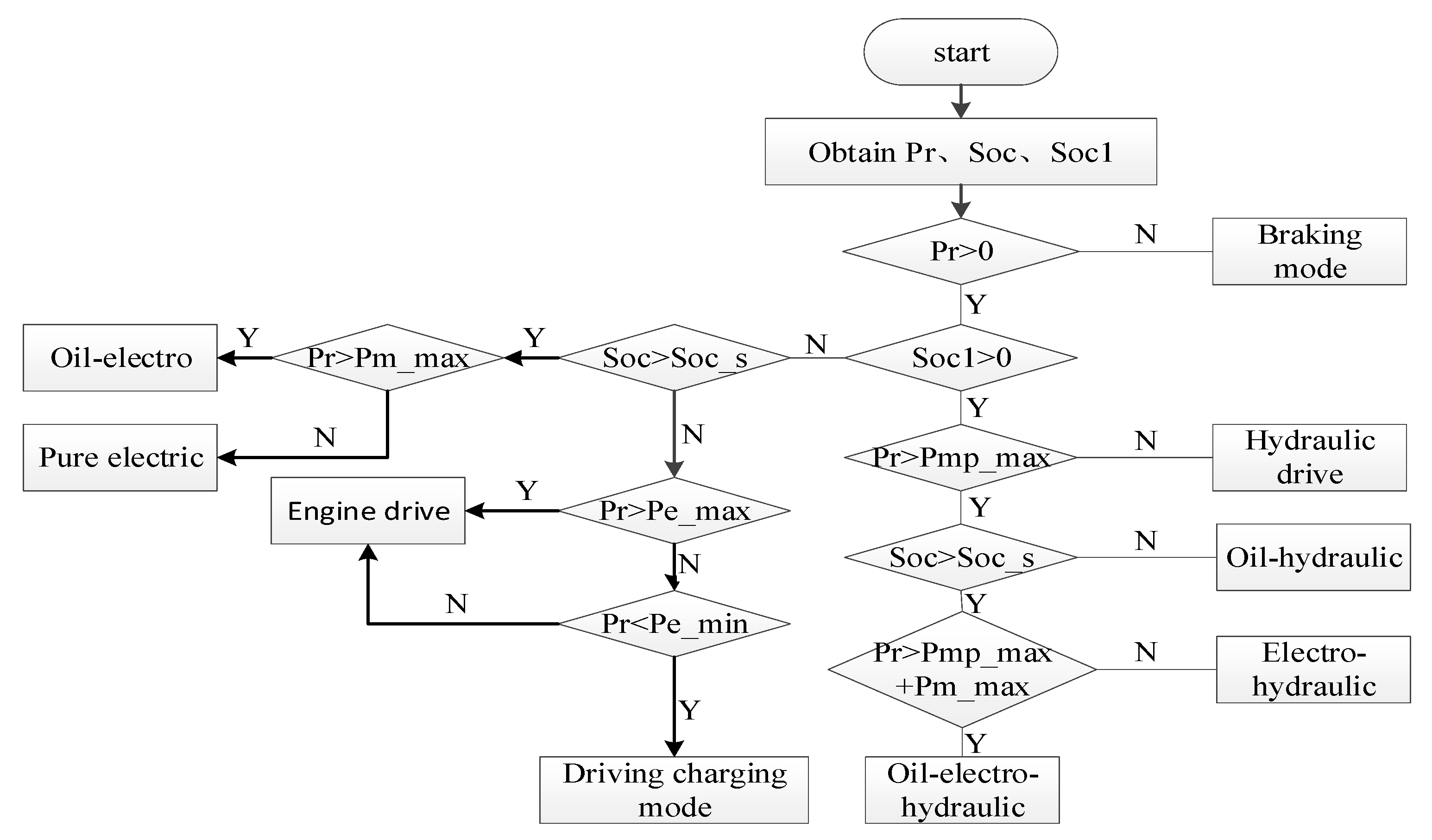
In the parallel hybrid system, which includes a variety of working modes, to ensure that the hydraulic pump can provide sufficient regeneration capacity and improve energy recovery efficiency during braking, this study chooses the control strategy of preferential use of hydraulic energy and electric energy. The specific mode selection logic is shown in Figure 2.
Under the premise of satisfying the power requirements, obtaining the best fuel economy for the whole vehicle is one of the goals of the hybrid electric vehicle energy management strategy. Firstly, the optimal working point corresponding to different power requirements in different modes is obtained via offline optimization, and a MAP table is made. Based on the result of mode selection, the optimal working point that meets the current vehicle power demand is then determined and applied, thereby achieving the optimal power system efficiency.
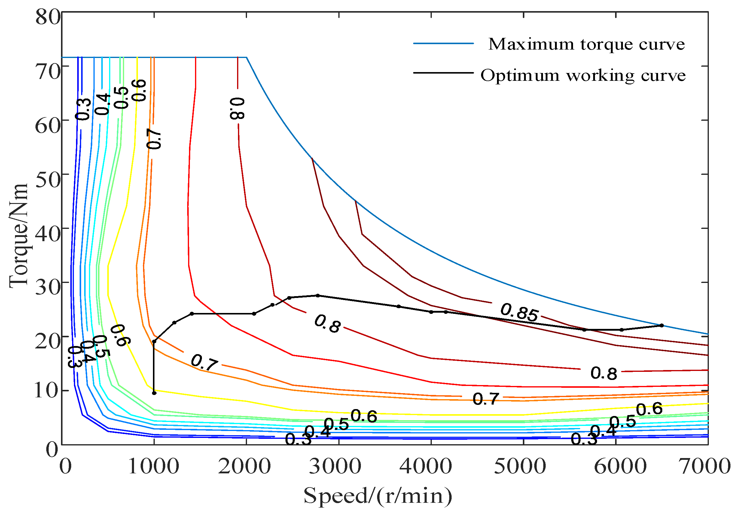
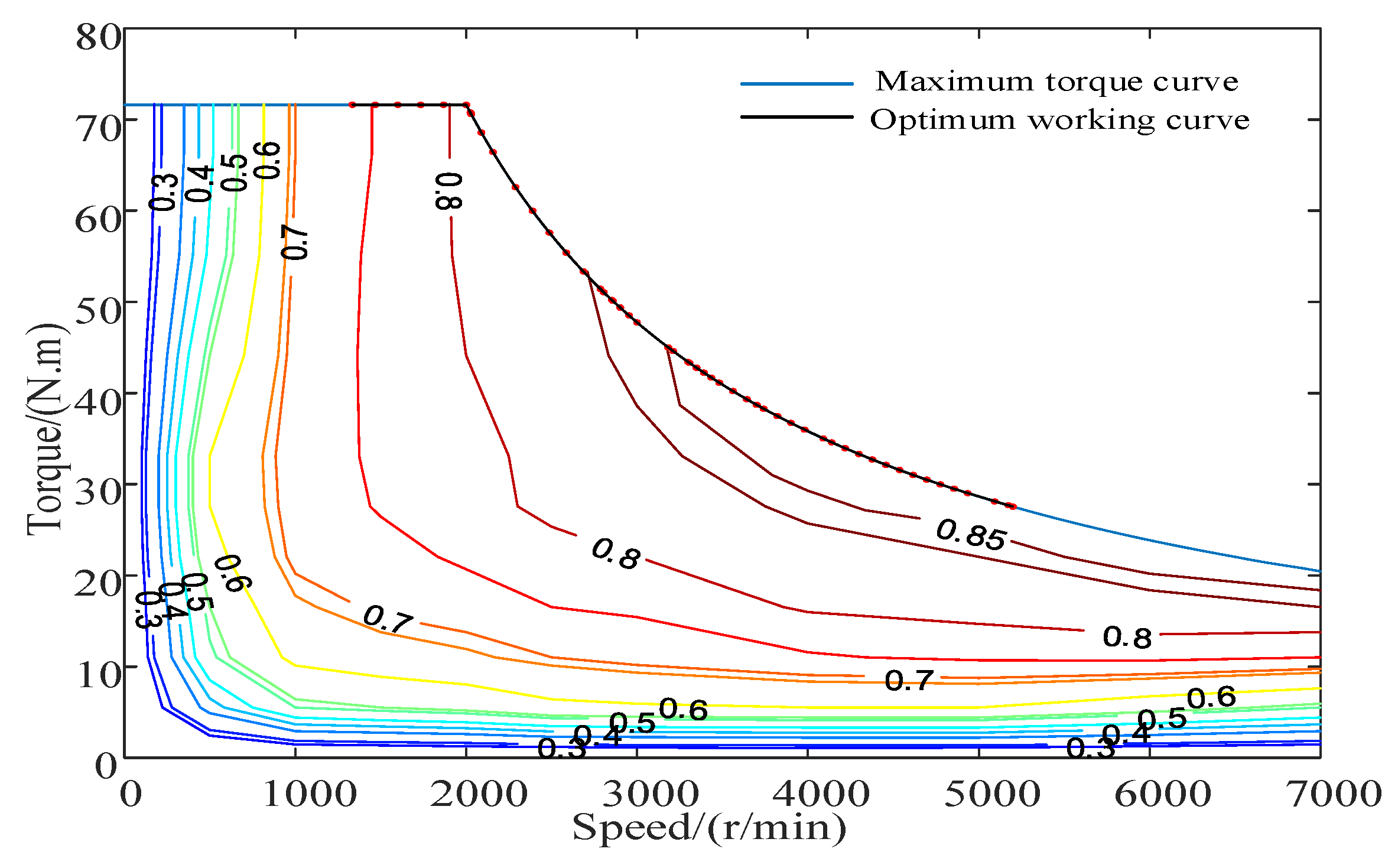
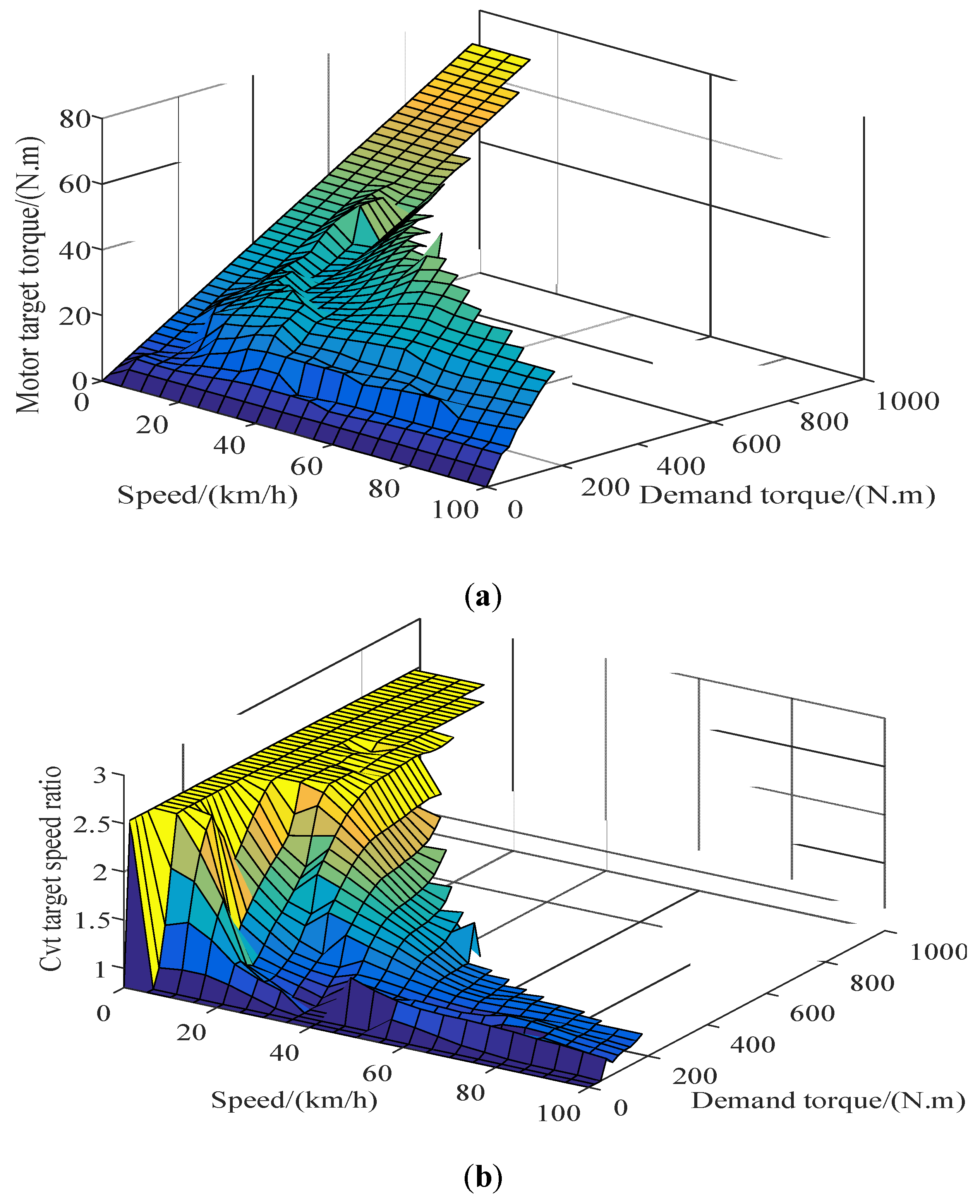
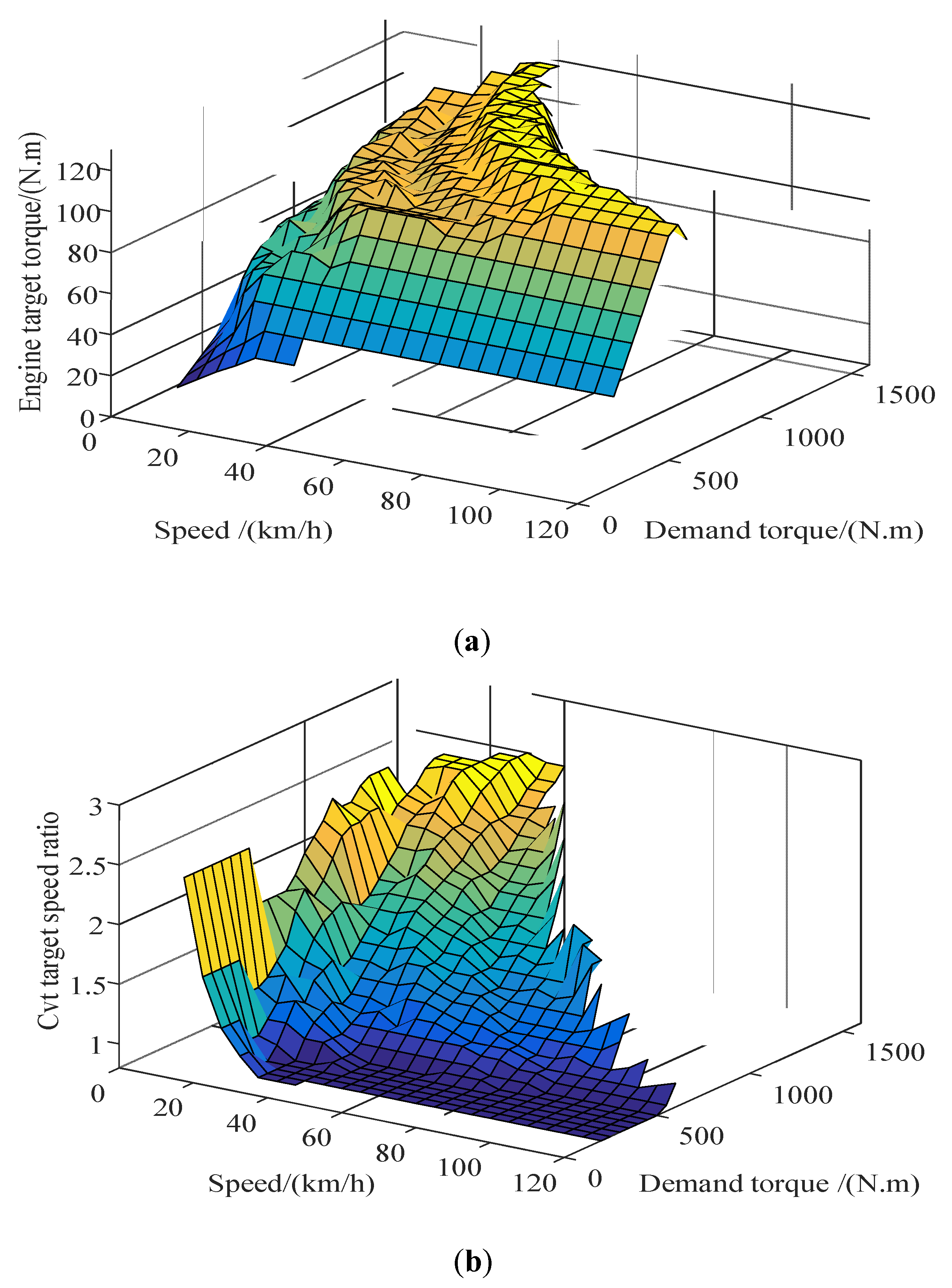
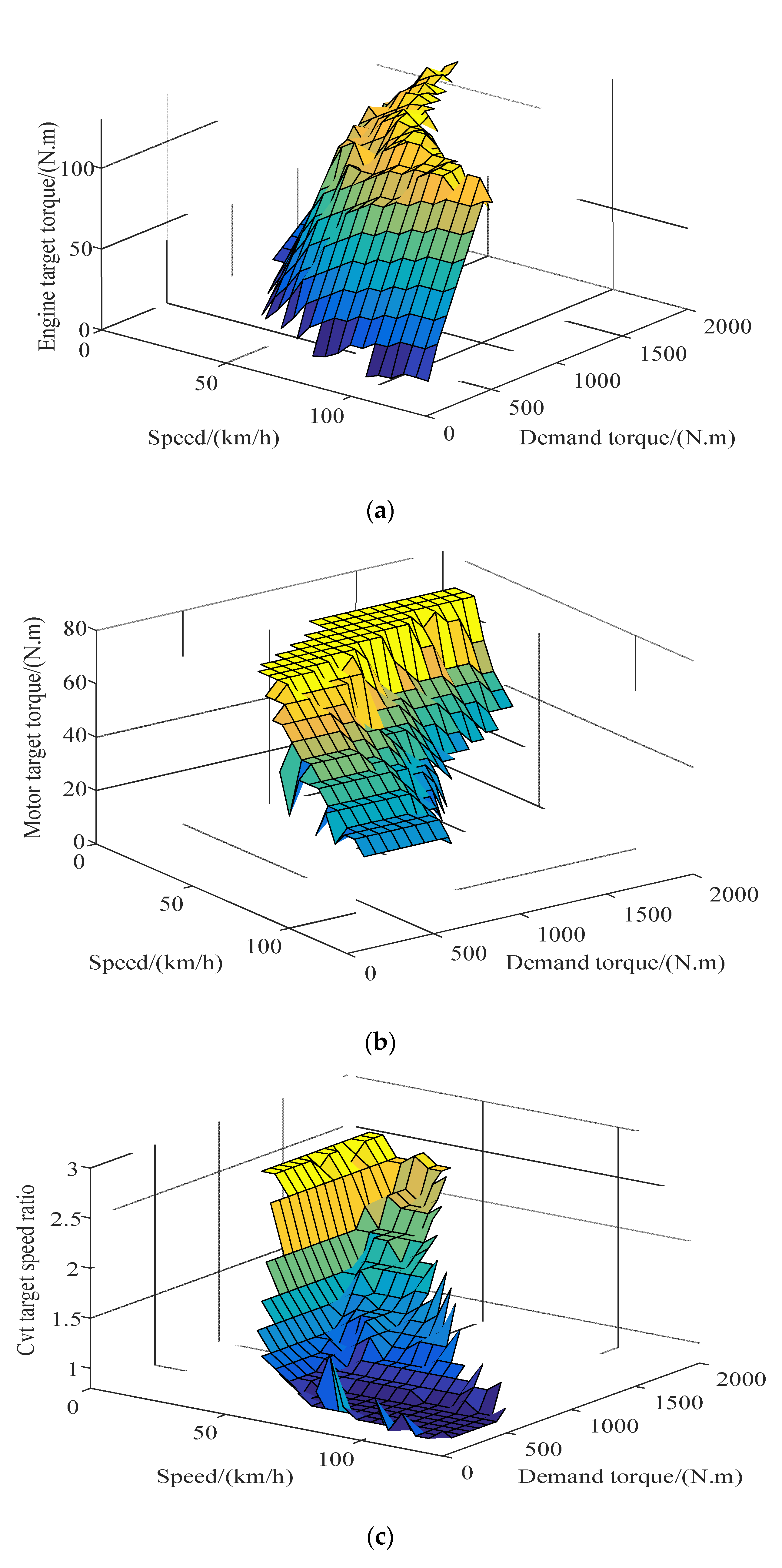
When the hybrid electric vehicle is operating in the hydraulic pump/motor single drive mode, its operating point is directly determined according to the required power, because the CVT transmission efficiency model was established by interpolation, and the CVT speed ratio range was obtained, whereas when the hybrid electric vehicle is operating in the engine or motor alone drive mode, the engine or motor operating point can be adjusted via continuously variable transmission (CVT). While the demand power is satisfied, the efficiency of itself is optimized, and the working point corresponding to the optimal efficiency is the optimal working point of the engine or the motor. Under the condition that the demand power is satisfied and each key component of the power source is constrained by itself, the optimization problem, wherein the transmission system efficiency is the objective function, is solved, and the optimal working curves of the motor and the engine, when either is working alone, can be obtained. These curves are shown in Figure 3 and Figure 4, respectively.
For hybrid systems, if the CVT efficiency loss is neglected when the engine and motor work together, Equation (1) is used.
P r = P e + P m = T e ω e + T m ω m ω e = ω m = ω r ω e_min ω e ω e_max ω m_min ω m ω m_max T s_min T e T e_max T m_min T m T m_max
P r , P e , and P m represent the vehicle demand power, engine power, and motor power, respectively, ω e and ω m denote the engine and motor speeds, respectively, i c v t indicates the transmission speed ratio, and T e and T m refer to the engine and motor torques, respectively.
When the motor is operating in the drive mode, the efficiency of the hybrid system can be expressed as
η 1 = P m + P e P m η d η m + P e η e = ( T m + T s ) ( T m η d η m + T e η e )
In the formula, η e , η m , and η d are engine efficiency, motor efficiency, and battery discharge efficiency, respectively.
When the motor is operating in the power generation mode, the efficiency of the hybrid system can be expressed as
η 2 = [ P e P m ( 1 η m η c ) ] ( P e / η e ) = [ T e T m ( 1 η m η c ) ] ( T e / η e )
η c is the battery charging efficiency
According to Equation (1), there are multiple combinations of ( ω r , T r ) on the premise that the engine and motor torques and speeds meet their constraints. The torques and speeds of the engine and motor in each combination, and the charge and discharge efficiencies of the engine, motor, and battery at this operating point can be substituted into Equation (2) or Equation (3) to calculate the total efficiency corresponding to each group of operating points. The most efficient combination ( ω e , T e ) , ( ω m , T m ) 
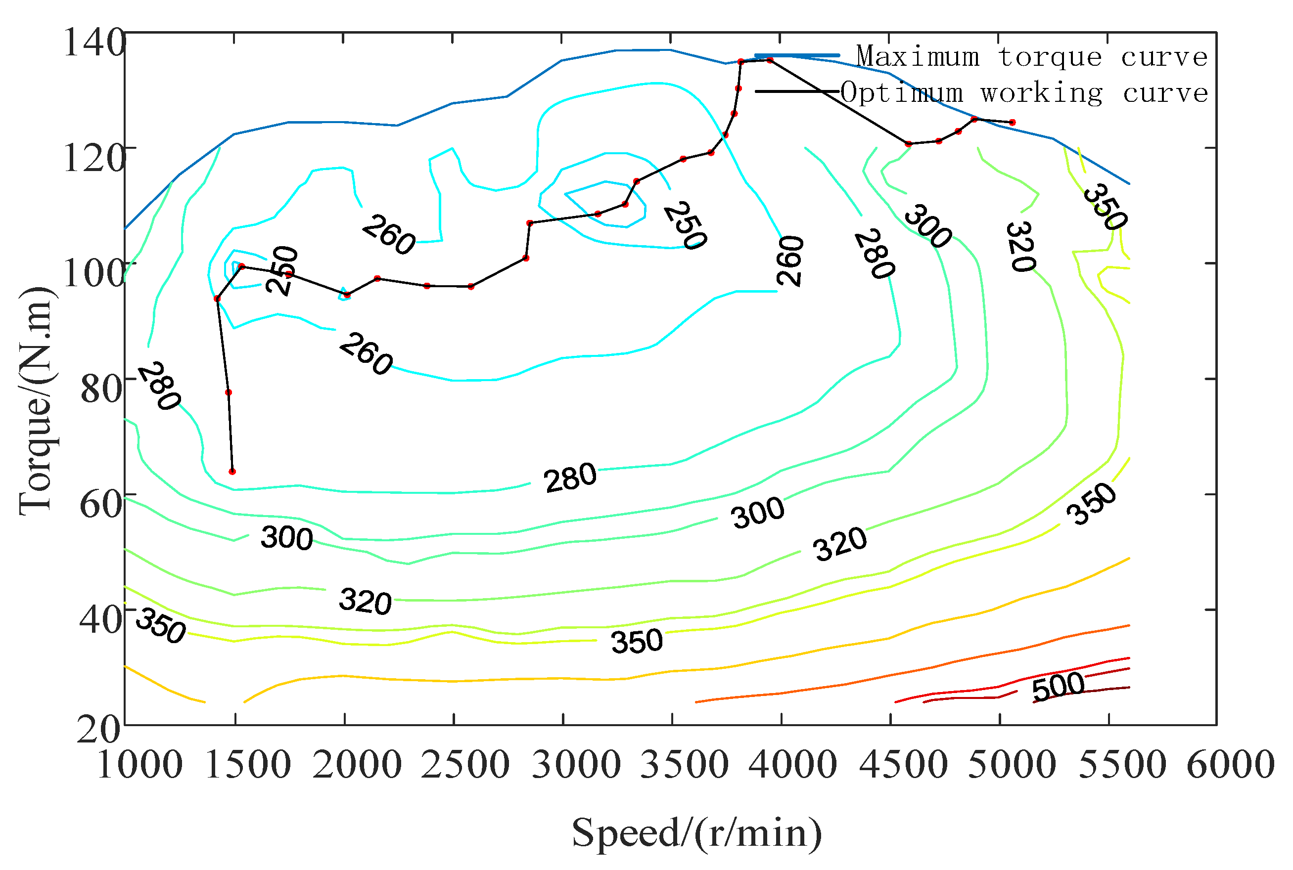
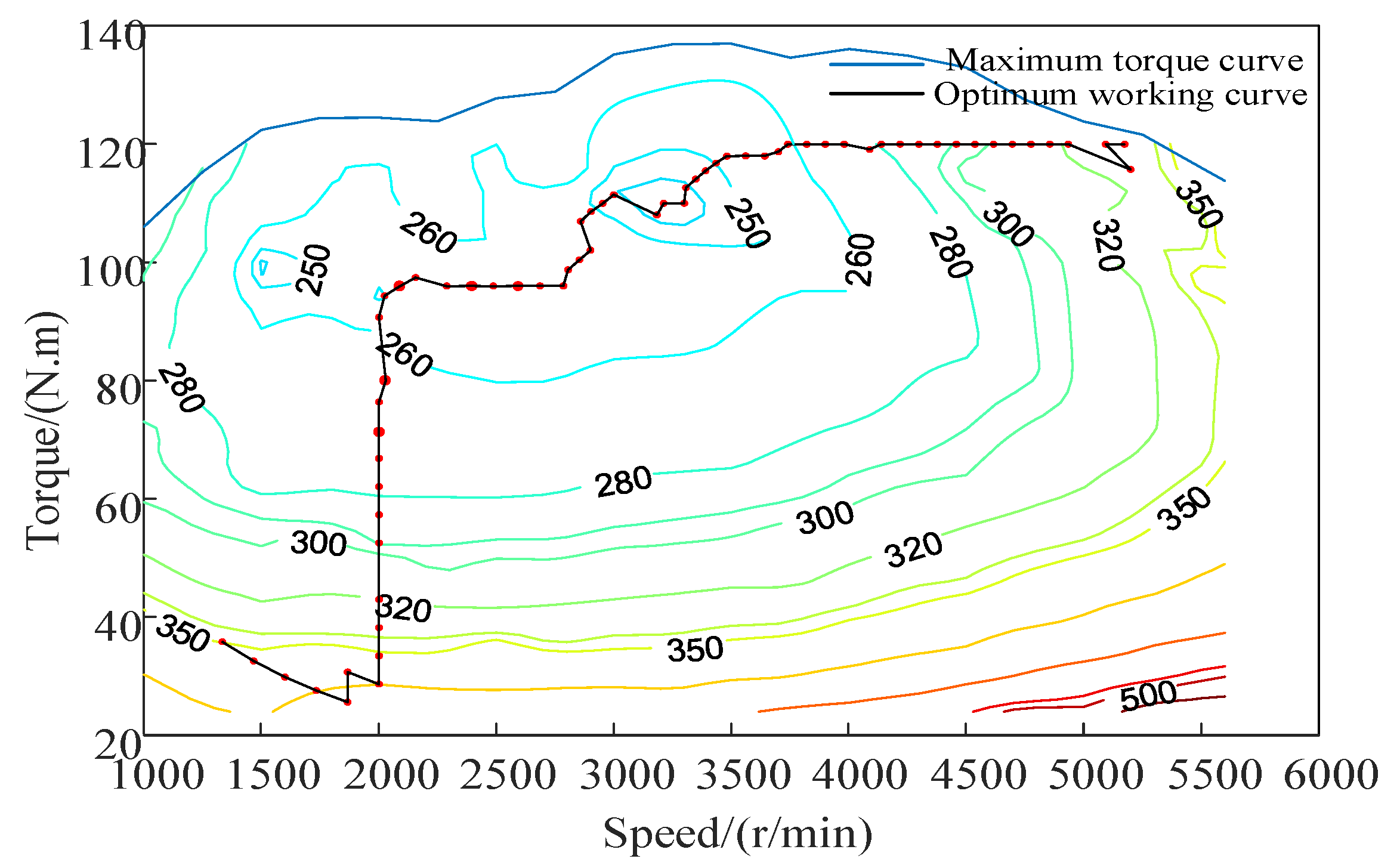
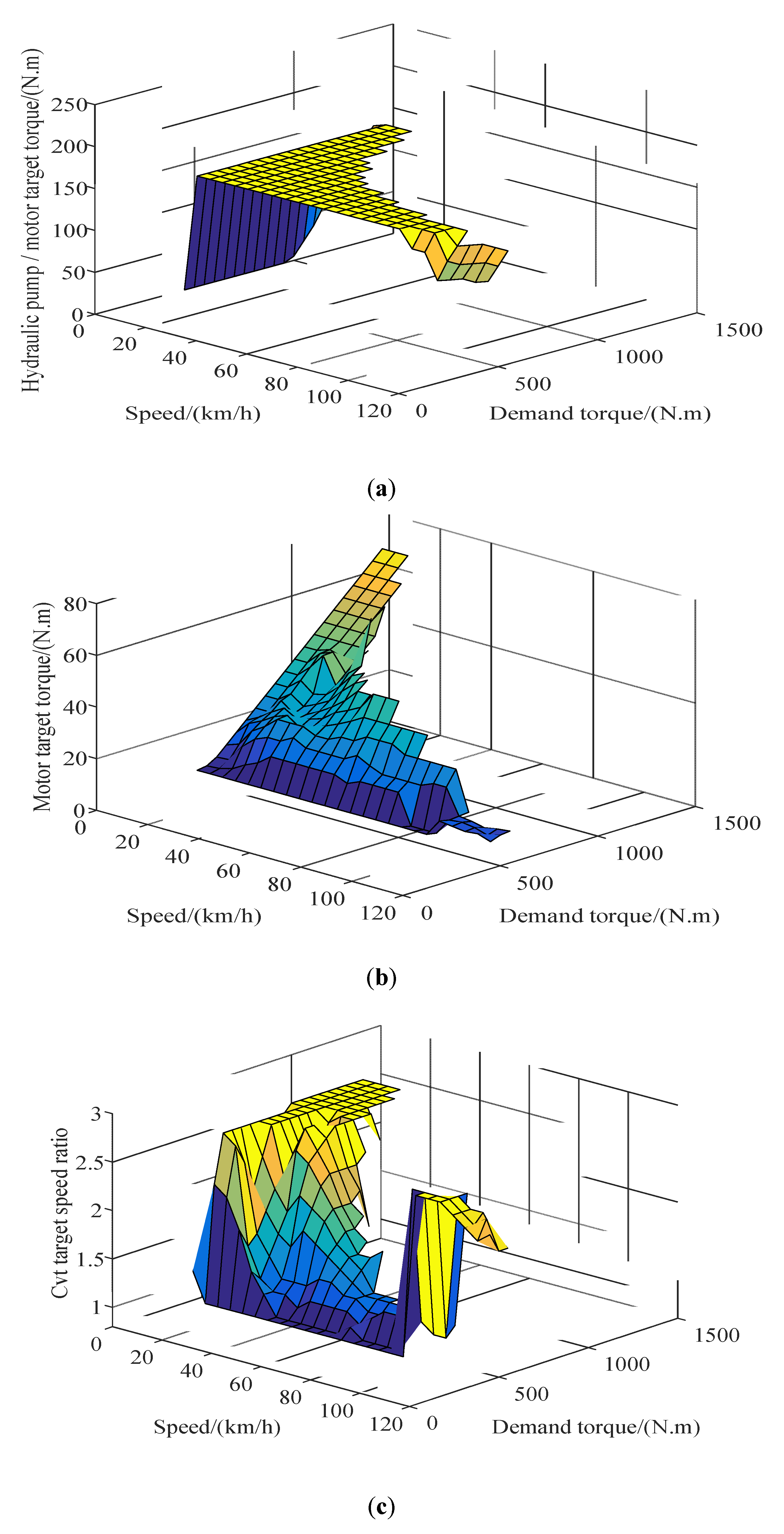
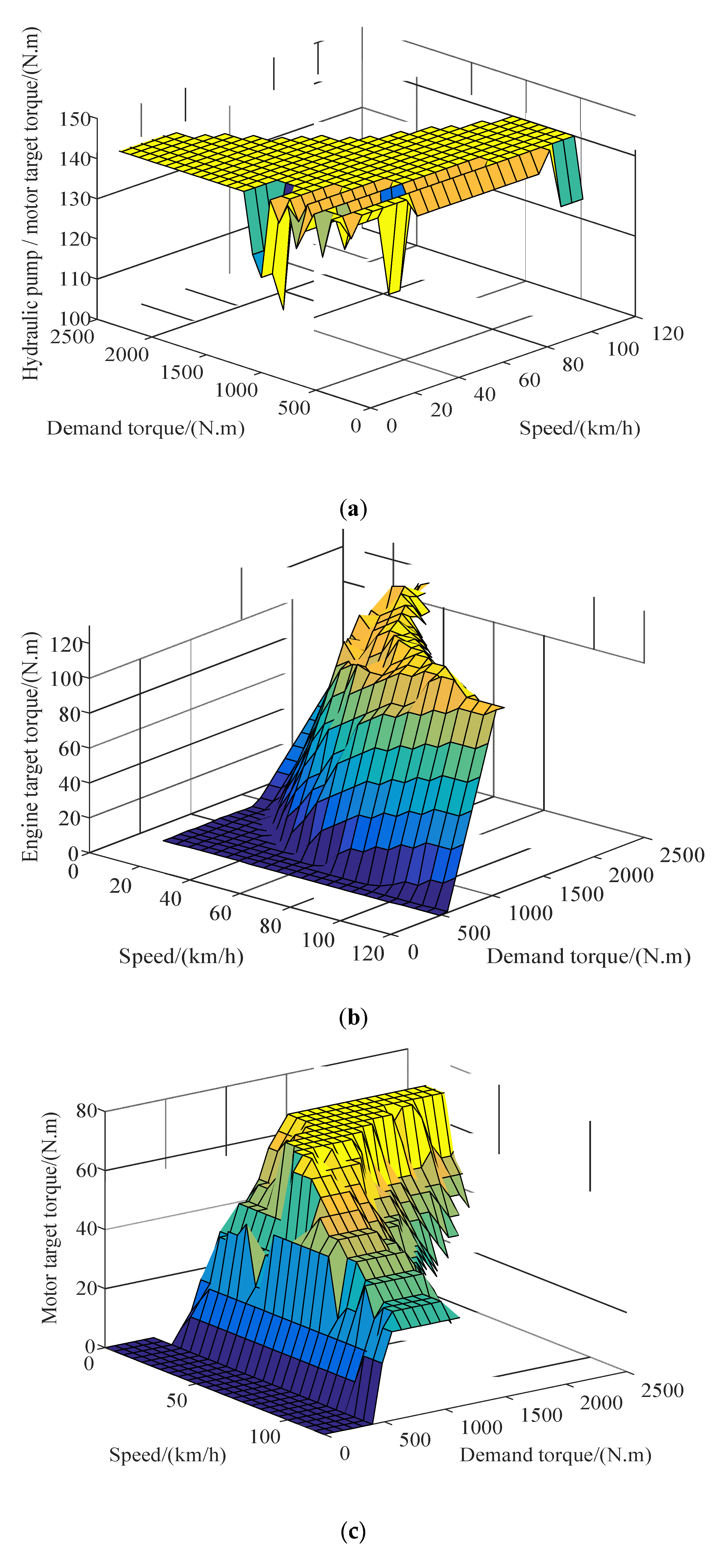
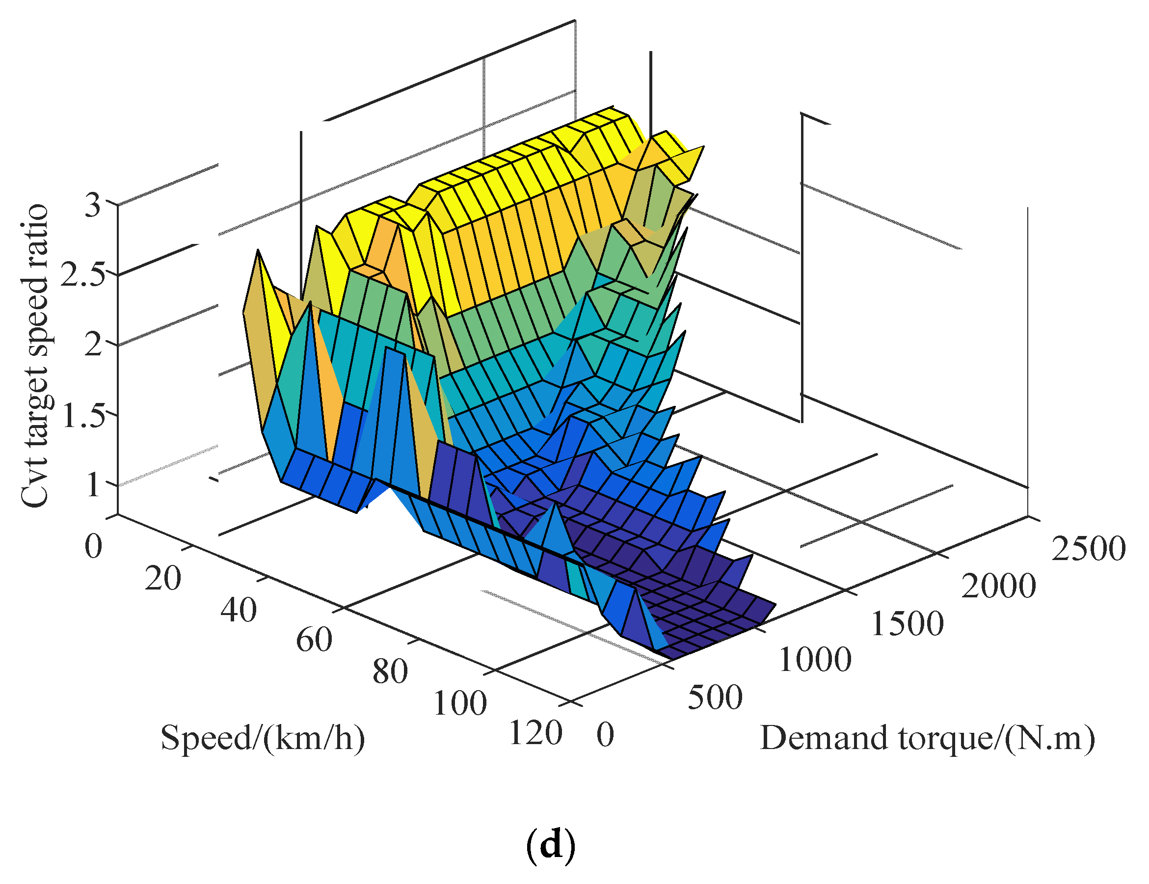
represents the best operating points of the engine and motor. In this way, the best working curves of the engine and the motor can be obtained. For the charge-depleting (CD) mode, the best working curves of the engine and motor combined drive are shown in Figure 5 and Figure 6, respectively.

3.2. Multi-objective optimization problems and their conversion

Under the premise of satisfying the vehicle power performance, achieving the Pareto optimal solution of the two objective functions is equivalent to achieving the two optimal goals for hybrid electric vehicle energy consumption and vehicle manufacturing cost. This study uses a linear weighting method to convert a multi-objective function based on energy consumption and vehicle manufacturing cost into a single objective function:
F ( x ) = ω 1 f u e l ( x ) f u e l u n o p t + ω 2 c o s t ( x ) c o s t u n o p t
where f u e l u n o p t and c o s t u n o p t represent the initial energy consumption and vehicle manufacturing cost, respectively, before optimization, and ω 1 , ω 2 are weighted values, wherein ω 1 = 0.8 and ω 2 = 0.2.
In terms of optimizing variable selection and constraint setting, to make the battery capacity meet the electric vehicle mileage index, the hydraulic pump/motor has to have sufficient regenerative braking force, but its corresponding cost should be reduced as much as possible. The optimization problem then becomes more convenient to solve. This study selects engine peak power P e m a x , motor peak power P m m a x , ratio m a x _ f a c t o r of maximum operating power of the engine to its peak power, ratio m i n _ f a c t o r of engine minimum operating power to peak power, and CD–CS mode switching value S o c _ s . That is, X = [ P e m a x , P m m a x , m a x _ f a c t o r , m i n _ f a c t o r , S o c _ s ] are optimized variables for the joint optimization of energy management strategy parameters and dynamic system parameters. The vehicle’s dynamic index (maximum speed is 180 km/h, 0~100 km/h acceleration time is 12.46 s, and the maximum climbable gradient is 40%) is used as an optimization constraint to ensure that the optimization results meet the vehicle power requirements.

3.3. Energy Management Strategy and Optimization of Power System Components Parameters

After the multi-objective problem is transformed into a single-objective problem, this article defines the fitness function, which simplifies the manufacturing cost of the whole vehicle power system to the cost of the engine and the motor. The following Equation (5) is obtained [11,12,13],
cos t ( X ) = 849 + 12.236 P e m a x + 10.888 P m m a x
In the formula, P e m a x and P m m a x are the peak powers of the engine and the motor, respectively.
Genetic algorithms are then used to optimize energy management strategies and power system parameters:
  • Because the optimization variables X are continuous variables, the real coding method is selected to encode the variables, and the upper and lower limits of each variable are set, as listed in Table 3.
  • The algorithm parameters are set, such that the maximum evolution algebra is 40, the population size is 100, the number of elites is 8, the crossover probability is 0.3, and the original population is randomly generated.
  • The number of iterations is checked for whether it reaches the maximum. If not, the vehicle simulation model is run to output the optimal fitness value and average fitness value of the contemporary population, and the process is continued. Otherwise, the optimal solution to the previous generation is outputted, and the process is ended.
  • The optimal fitness value is checked for whether it is less than or equal to the set target fitness value. If yes, the optimal fitness value and its corresponding optimal individual are outputted, and the process is ended. Otherwise, the current population is selected, crossed, and mutated.
The optimization results of the genetic algorithm are shown that the fitness value decreases with the evolution of the population, and finally converges to 0.93. The corresponding optimal individuals are ( P e m a x , P m m a x , m a x _ f a c t o r , m i n _ f a c t o r , S o c _ s ) = (57.32, 32.68, 0.89, 0.16, 0.32)
According to the comparison of the simulation results of the unoptimized and GA-optimized in Table 4, the manufacturing cost of the whole vehicle power system is reduced by 1.7%, and the energy cost per 100 km is reduced by 8.3%.
Finally, to verify whether the parameter matching result of the power system is reasonable, the vehicle facing-forward simulation model is established based on the MATLAB/Simulink platform, and dynamic simulation results showed that the acceleration time to 100 km is 11.8 s, and the maximum speed is 177 km/h. The maximum grade is 40.24%, and the speed is 30km/h. At the time, the maximum gradeability can reach 39.78%; in summary, the optimized hybrid system parameters can meet the vehicle dynamic performance requirements.

4. Energy Management Strategy based on the Lowest Instantaneous Energy Cost

4.1. Energy Management under Driving Conditions

In this article, the minimum instantaneous energy consumption cost is the objective function; the vehicle travel demand torque T r , vehicle speed v , hydraulic accumulator S o c 1 , and battery Soc are the state variables; the hydraulic pump/motor torque T p m , motor torque T m , engine torque T e , and CVT speed ratio i c v t are the control variables. Because this study deals with not only hydraulic regenerative braking, but also motor regenerative braking [14], the hydraulic energy is equivalent to electric energy when the cost of hydraulic energy consumed is calculated, and the instantaneous cost is
Cos t = 1 3600 ( j f P e b e 1000 ρ + j e ( P m η m η b + P p m η p m ) )
where Cost is the sum of the costs of fuel, electricity, and hydraulic energy consumed per unit time (yuan/s), j f is the price of gasoline (yuan/L), and j e is the price of electrical energy (yuan/ kw · h ). P e , P m , P p m represents the output power of the engine, motor, hydraulic pump/motor (kw). b e is the fuel consumption rate ( g / ( kw · h ) ) ; ρ is the density of gasoline ( g / c m 3 ) ; η m   and   η b represent the motor, battery efficiency; η p m represents the mechanical efficiency of the hydraulic pump/motor in motor mode.
The objective function and constraints can be expressed as
min ( Cos t ( T p m , T m , T e , i c v t ) )
{ ( T e   +   T m )   ·   i c v t i 0 η c v t   +   T p m   ·   i 1   =   T r e q 0     n e     n e m a x 0     n p m     n p m m a x T e     T e m a x ( n ) | T m |     T m m a x ( n ) T e   +   T m     T cvt_in_max T p m     T p m m a x ( n ) P m ( η m η b )     P b m a x 0.83     i c v t     2.50
To obtain the optimal values of each power source and transmission under different vehicle conditions, the grid traversal algorithm is used to solve any set of state variables, and the MAP table is made to facilitate real-time control. The algorithm flow is shown in Figure 7.
For different drive modes, the optimization results are different. In the single power source mode, because the hybrid system scheme adopted in this study does not have a transmission on the rear axle of the vehicle, the operating point cannot be optimized in the hydraulic pump/motor drive mode. Therefore, this study examines only the optimization of energy cost in the purely electric mode and engine driving mode. In the purely electric mode, the parts related to the engine and the hydraulic pump/motor in the optimization Algorithm 6 and Constraint Condition 8 are omitted, and the results shown in Figure 8a,b can be obtained via offline optimization. Similarly, for the engine mode, the optimization results are shown in Figure 9a,b.
The hybrid drive mode includes the electro–hydraulic hybrid drive, oil–electric hybrid drive, and oil–electro–hydraulic hybrid drive. For each mode, corresponding changes are similarly made to the optimization algorithm and constraints, and offline optimization is performed to produce the results shown in the Figure 10, Figure 11 and Figure 12.

4.2. Energy Management under Braking Conditions

For a hybrid electric vehicle with a regenerative braking system, regarding the distribution of the braking force, it is necessary to solve the problems of not only the distribution of the braking force of the front and rear axles but also the distribution of the regenerative braking force and the frictional braking force. Thus, considering the high efficiency of the hydraulic regenerative braking system for recovering energy, this study uses the hydraulic pump/motor as the main way and the motor as the auxiliary way of providing the regenerative braking force. At the same time, the friction braking force is used to coordinate and to meet the driver’s demand braking force to achieve maximum energy recovery.
Figure 13 shows the braking force distribution curve designed for the oil–electric–hydraulic hybrid electric vehicle. The OABCD curve is a braking force distribution curve for when the hydraulic accumulator is S O C 1 < 1 and the battery SOC > 0.9 , the O A B B CD curve for when the hydraulic accumulator is S O C 1 < 1 and the battery SOC 0.9 , and the O A B CD curve for when the hydraulic accumulator is S O C 1 = 1 and the battery SOC < 0.9 . Point A indicates the maximum braking force that can be transmitted to the rear wheel when the hydraulic pump/motor is working alone; point A indicates the maximum braking force that can be transmitted to the front wheel when the ISG motor is working alone. Meanwhile, point B indicates the sum of the maximum braking forces that can be transmitted to the wheels when the hydraulic pump/motor and motor are simultaneously operating. B , C , D are the intersections of the I curve and the braking strengths.
When the structural scheme of the hybrid system presented in this article is analyzed, the working point of the motor can be adjusted via the CVT transmission, but the working point of the hydraulic pump/motor cannot be adjusted, and thus the operating point of the motor can only be optimized. This inference considers that in the regenerative braking mode in which all motors participate, only the braking force distribution strategy is different and that there is no influence on the optimization process. Therefore, this section needs only to optimize the motor operating point in the motor regenerative braking mode. In this section, the kinetic energy recovered is used as the objective function, and the target torque of the generator and the CVT target speed ratio are optimized.
The objective function is
min ( P b η c v t η m η b )
In the formula, P b represents the braking power required to be transmitted from the motor to the wheel.
The constraints are
{ T m = T m b / ( i c v t i 1 η ) 0 < n 6000 | T m | T m a x ( n ) | P b η c v t η m η b | P b m a x 0.83 i c v t 2.50
The optimization results are shown in Figure 14.

4.3. Analysis of Simulation Results

To verify that the energy management strategy proposed in this article is effective in each mode, this study simulates under a driving cycle composed of multiple New European Driving Cycle (NEDC) working conditions. The results are shown in Figure 15.
As can be seen from Figure 15a, the driver model based on the PI controller has higher control accuracy. From a comparison of (a) and (b), it can be found that during the driving process, when the hydraulic accumulator SOC1 > 0, the hydraulic accumulator releases energy. Therefore, the hydraulic mode-based drive mode selection strategy proposed in this article achieves the expected control effect. From a comparison of (a), (b), and (c), it can be seen that during the braking process, the hydraulic accumulator SOC1 or the battery SOC has a significant rise, which indicates that the braking force distribution strategy not only can meet the braking demand but also can fully recover energy. It can also be seen from (c) that the battery SOC can still be maintained within a reasonable range after falling to a certain value. It can also be seen from (a), (d) that the torque distribution of the engine, the motor, and the hydraulic pump/motor can satisfy the torque demand of the entire vehicle. In the whole simulation process over the driving distance, because the hydraulic accumulator SOC1 returns to the initial state, the energy consumption includes only electric energy and fuel, wherein the electric energy is 5.88 degrees, the fuel is 4.99 L, and the total energy consumption cost is 38 yuan. Compared with the fuel consumption cost of the original model 100 km 8 L, the strategy proposed in this article saves costs by about 32.14%.

4.4. Simulation Comparison under Two Different Strategies

To better compare the proposed strategy with the minimum energy consumption cost strategy, the initial Soc of the battery is selected to be 0.8, and the initial value of the hydraulic accumulator Soc 1 is set to 1. Furthermore, the DP-based global optimized energy management strategy is simulated under the NEDC working conditions. The results are shown in Figure 16.
The simulation result Figure 16 shows that the DP-based energy management strategy can extend the cruising range by rationally utilizing the electric energy and can also maintain the balance when the battery Soc is low. The control effect of the strategy is also good, which can provide a certain evaluation point for the advantages and disadvantages of other strategies. Therefore, this strategy is compared with the instantaneous energy consumption cost minimum energy management strategy. The simulation results are shown in Figure 17.
It can be seen from Figure 17 that the instantaneous optimized energy management strategy has a faster rate of lowering the Soc in the pre-simulation battery, uses more power, and lowers the energy consumption cost, which has obvious cost advantages compared with the global optimized energy management strategy. When the battery Soc drops to around 0.3, its value is balanced, and the energy consumption cost increases significantly and gradually exceeds the energy consumption cost under the global optimized energy management strategy.

5. Conclusions

In this study, a new type of oil–electric–hydraulic hybrid power system is examined as the research object, and a driving mode based on hydraulic energy and electric energy is selected. A logic threshold energy management strategy based on the optimal working curve is proposed, and then the linear weight method is adopted. The multi-objective function, which aims at the energy consumption cost and the manufacturing cost of the whole vehicle power system, is converted into a single objective function, the optimization variables are selected, and the constraints are set. The genetic algorithm is used to optimize the energy management strategy parameters and power system components. The optimized power system parameters can meet the power performance requirements of the vehicle.
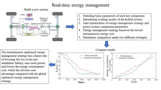
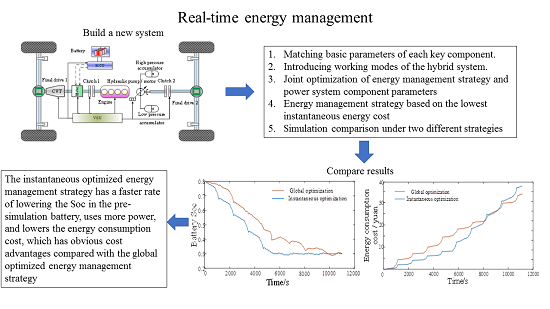
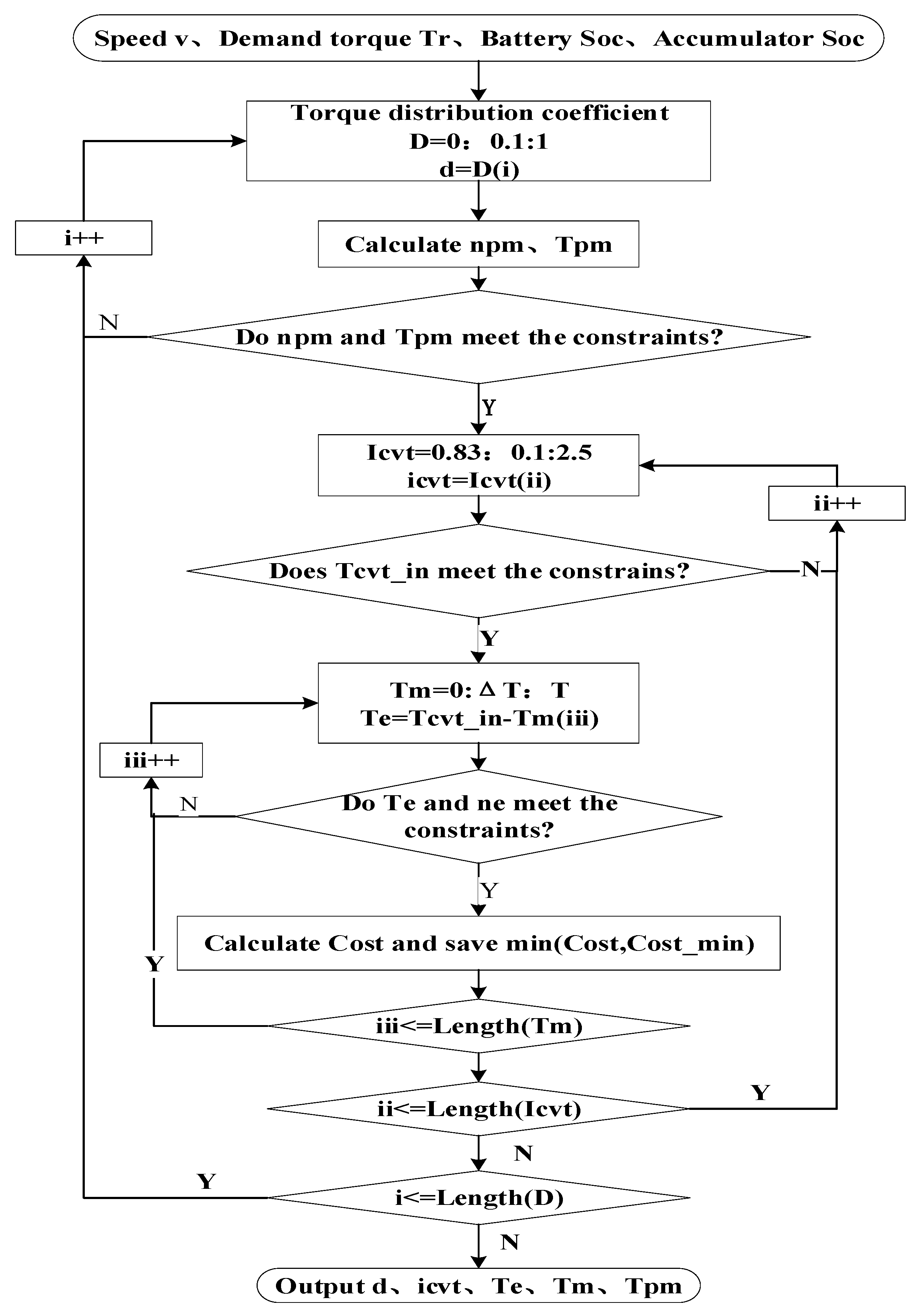
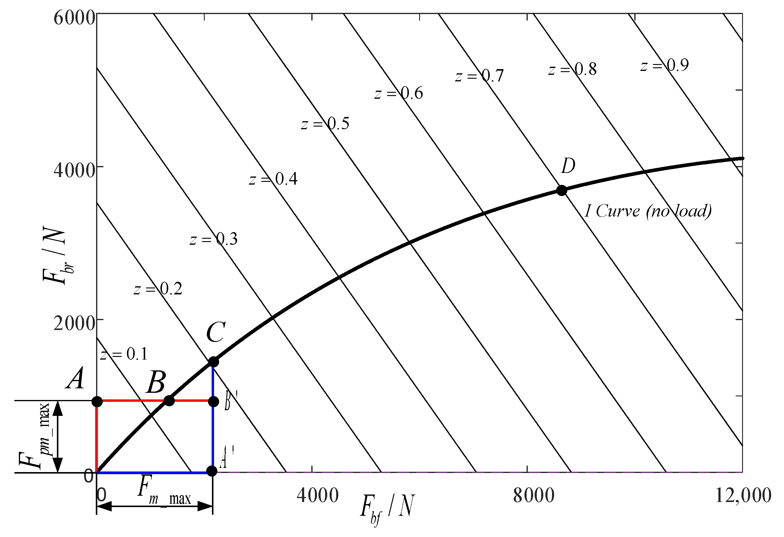
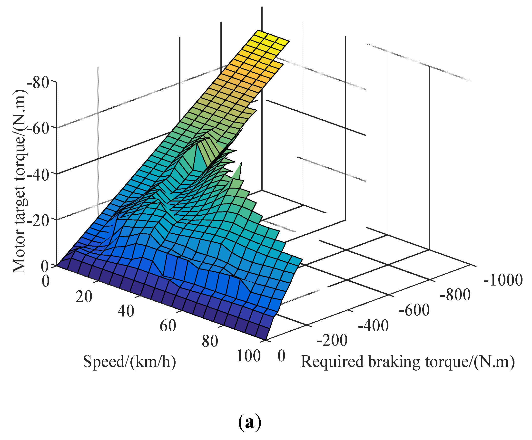
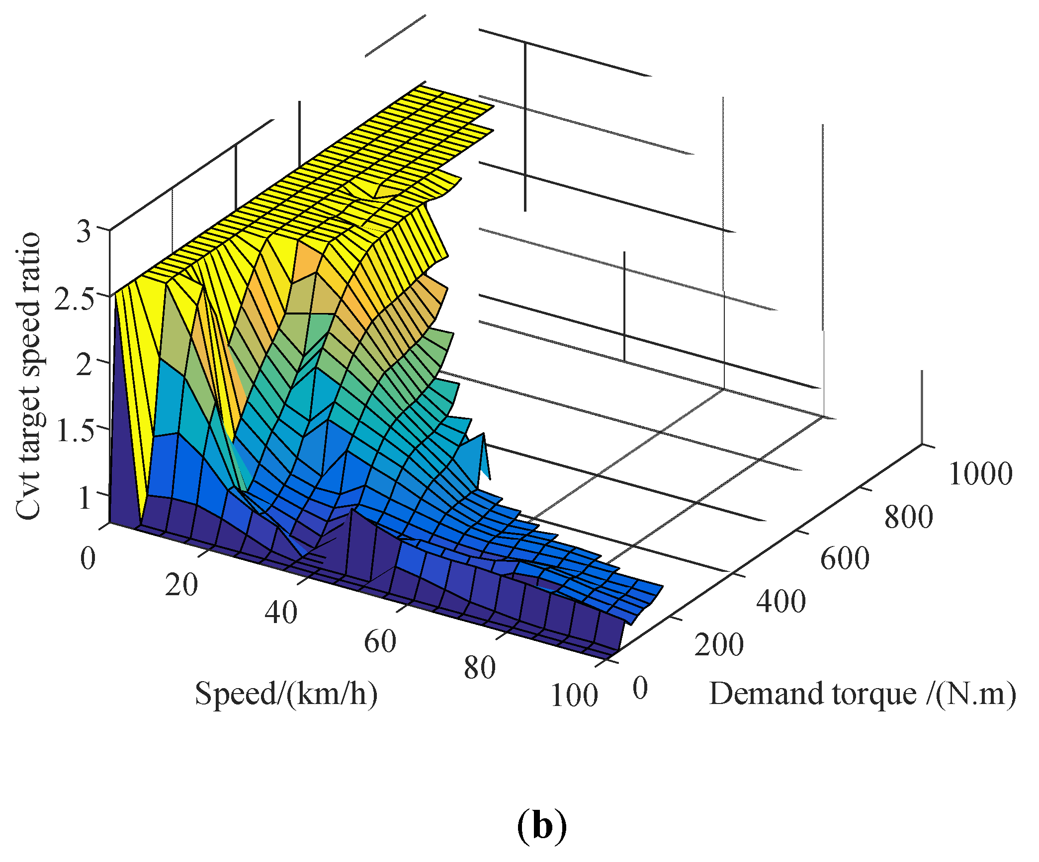
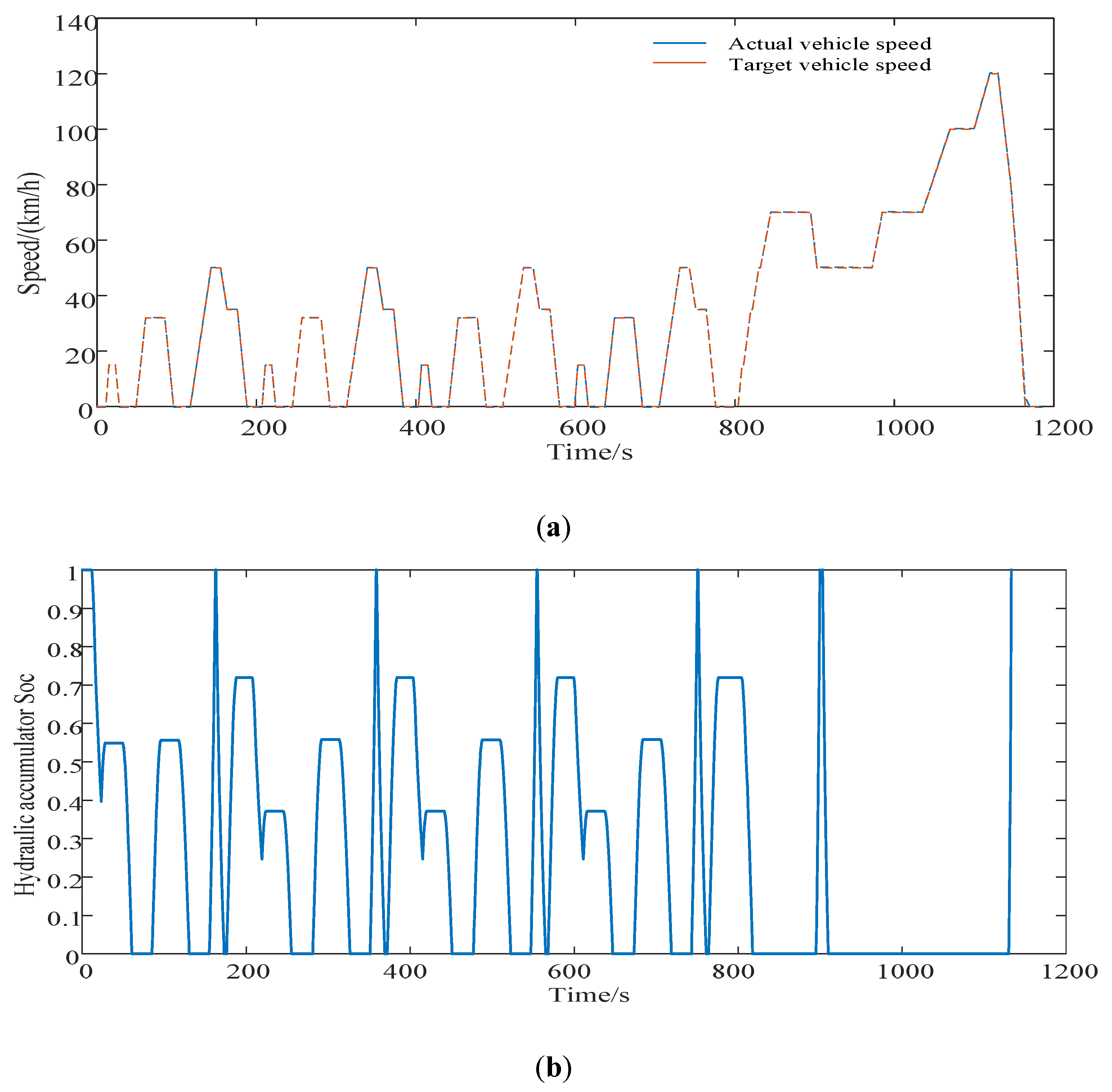
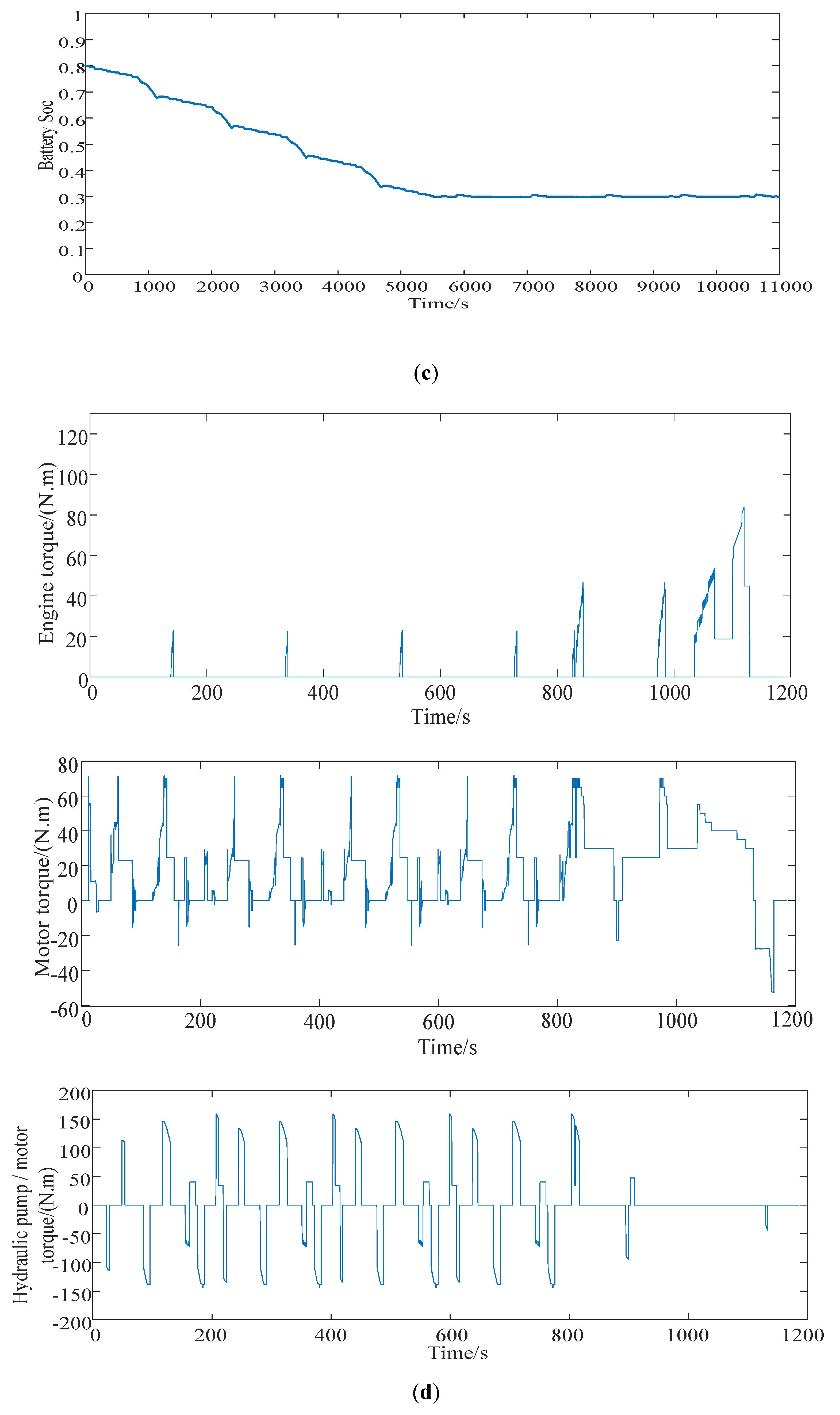
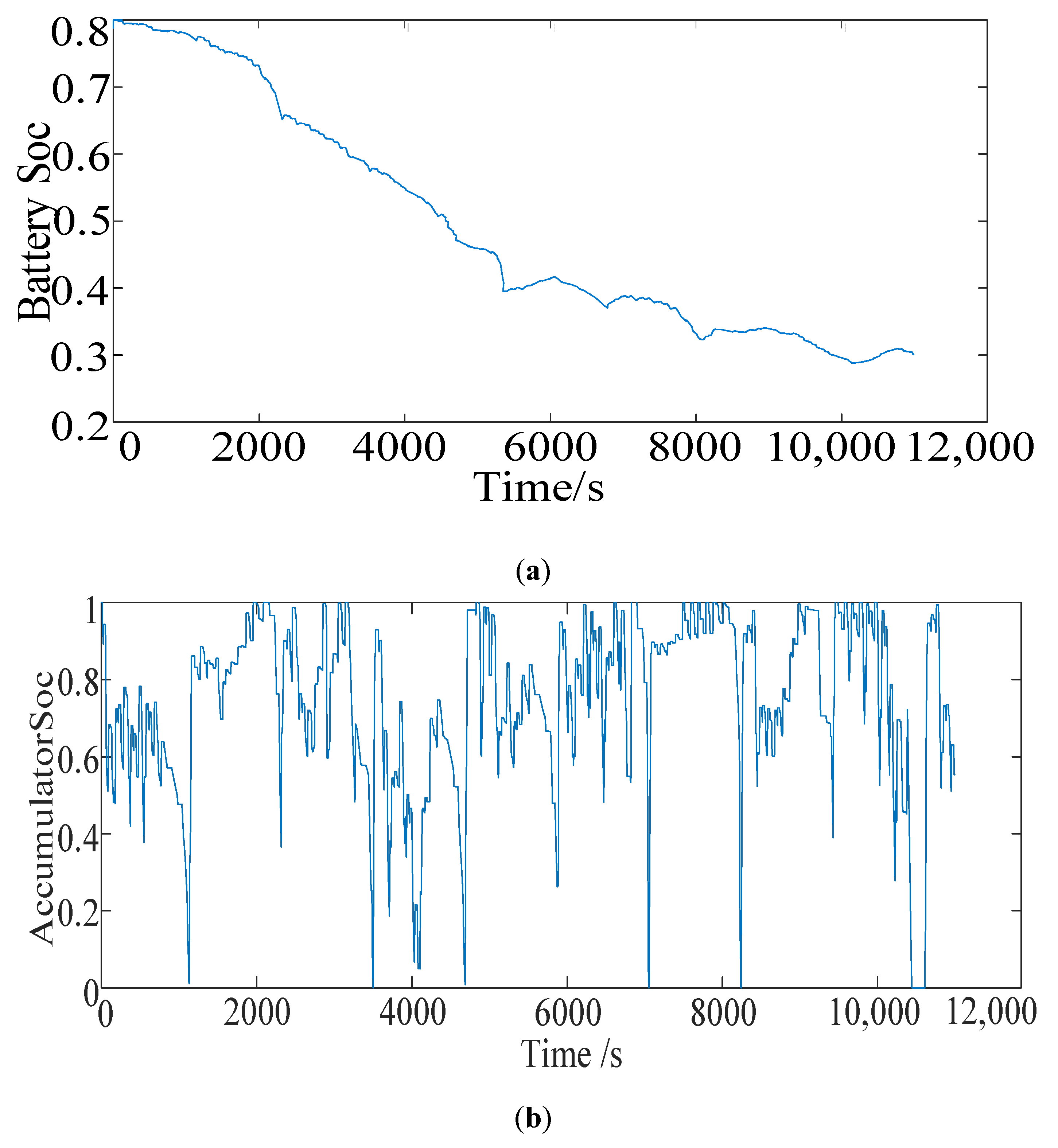
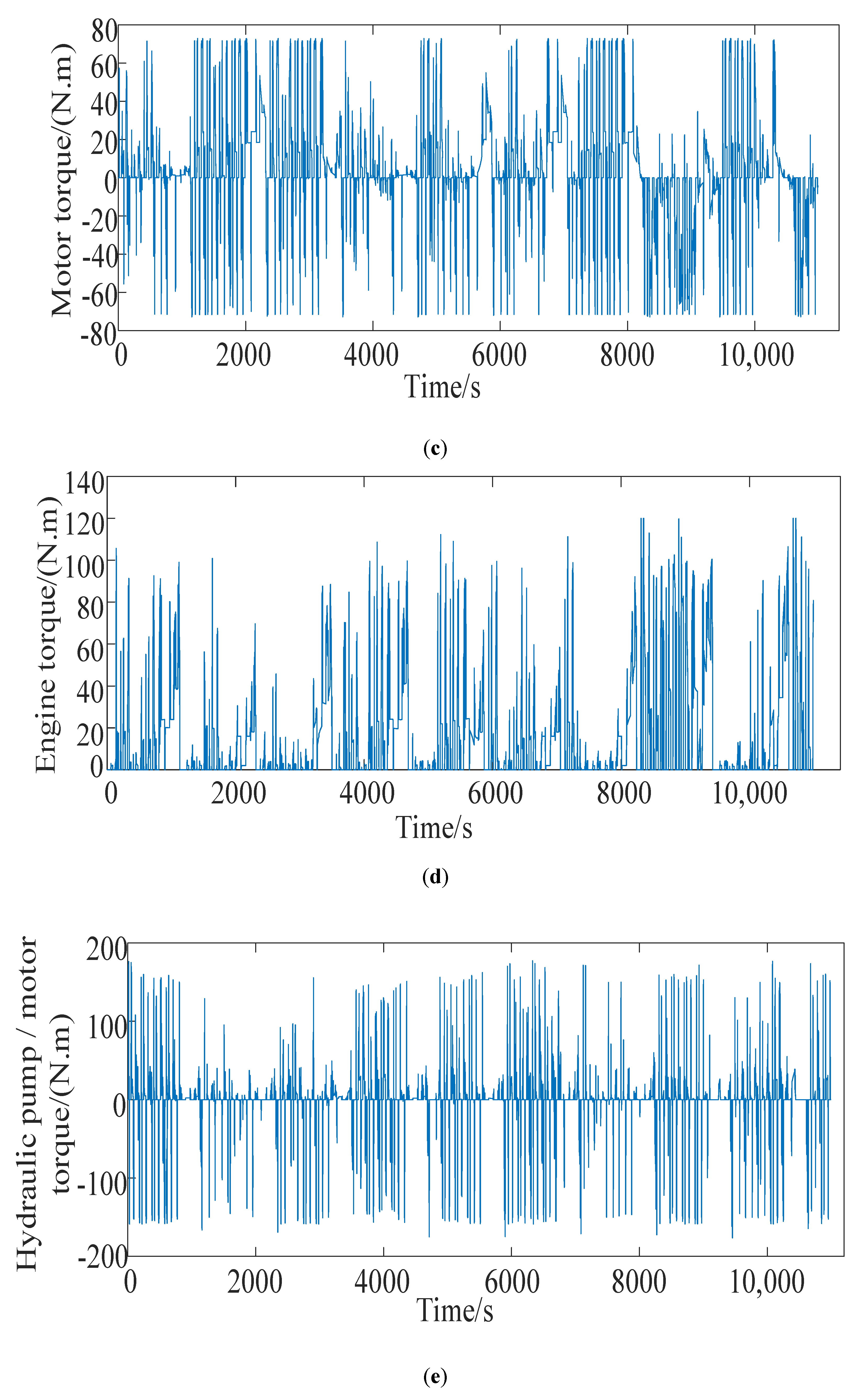
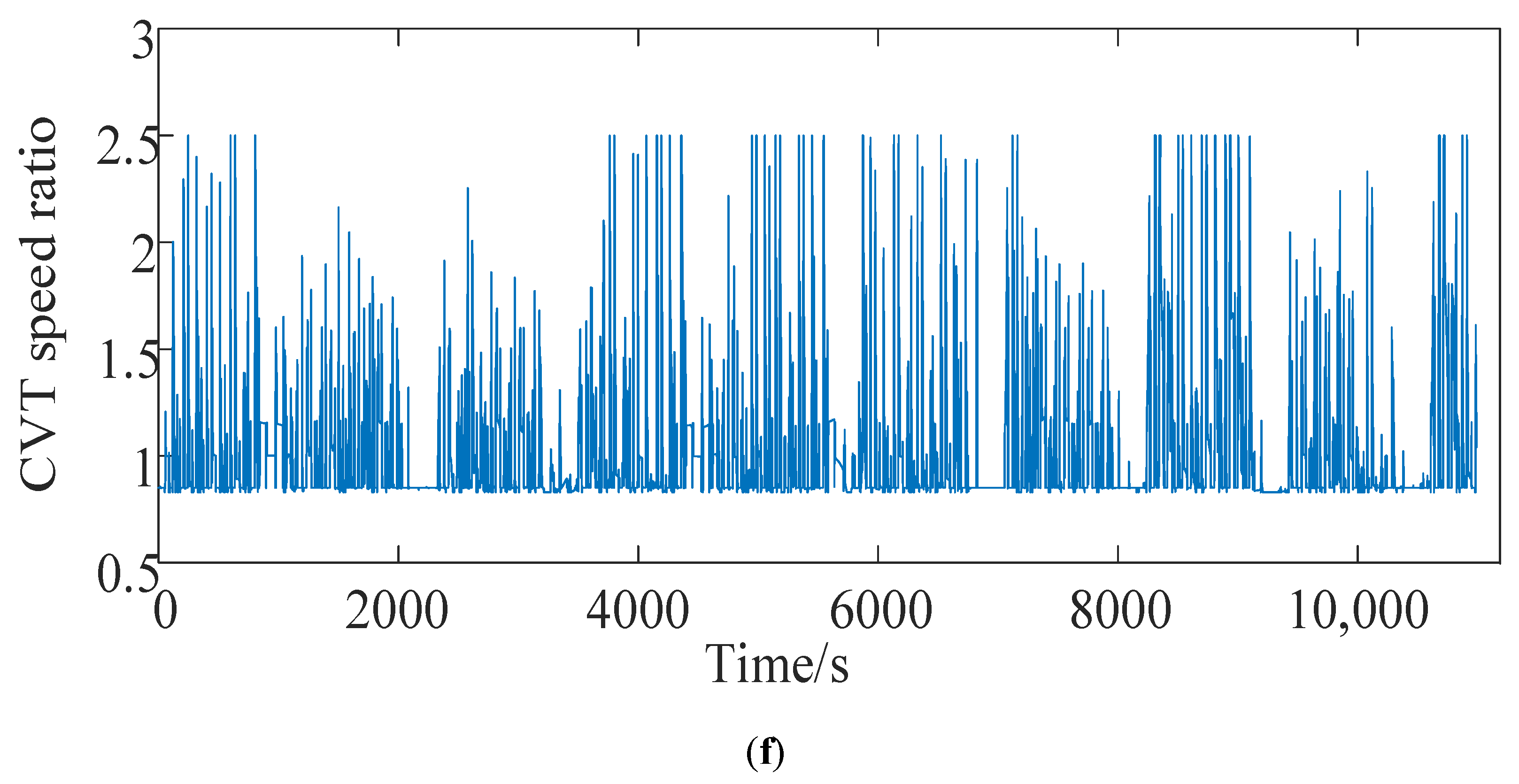
Aiming at managing energy when the vehicle is under driving condition, a real-time energy management strategy based on the lowest instantaneous energy consumption cost is proposed. The strategy uses the instantaneous energy consumption cost in the single power source driving mode or the hybrid driving mode as the objective function and utilizes the grid. The ergodic method solves the target values of different vehicle demand torques and vehicle speeds to form a MAP table for real-time control. For braking conditions, based on the braking force distribution strategy and ECE regulations for traditional four-wheel-drive vehicles, a braking force distribution strategy based on the highest energy recovery is proposed. The simulation results show that the energy management strategy proposed in this article can achieve reasonable distribution of torque and achieve the expected control effect, and saves about 32.14% compared with the fuel consumption cost of the original model 100 km 8 L.
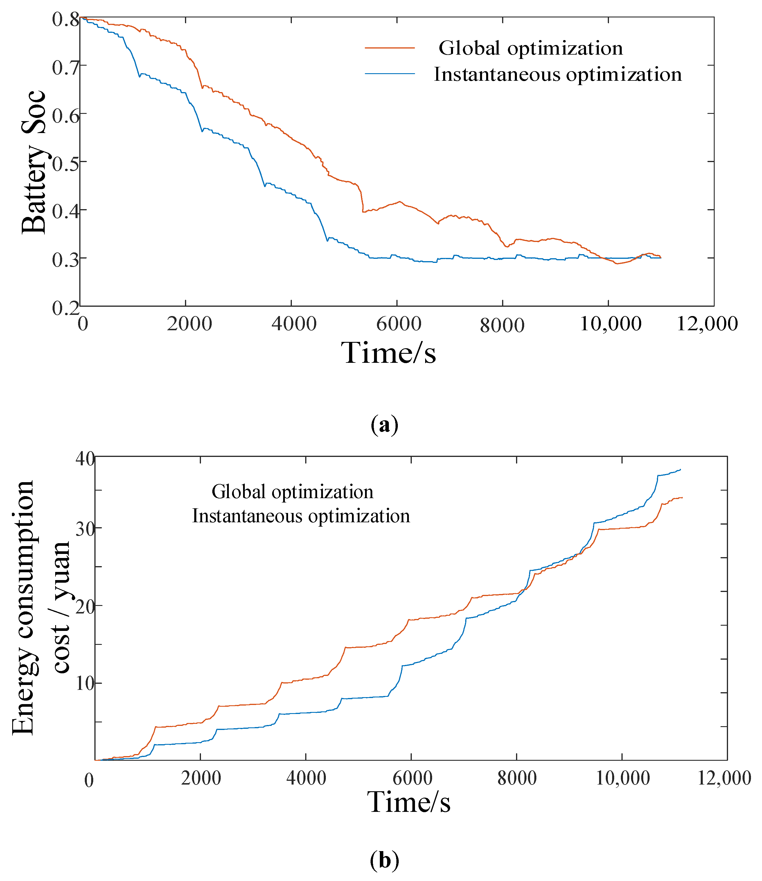
Simulation analysis of global optimization energy management strategy based on dynamic programming is performed, and the results prove that this strategy can be used as the basis for evaluating other strategies. The simulation comparisons under the NEDC working conditions show that the energy-saving effect of the real-time energy management strategy based on the minimum instantaneous energy consumption cost is similar to that of the global optimized energy management strategy.

Author Contributions

Y.Y. designed the oil–electric–hydraulic system and proposed the energy management control strategies; Z.Z. conducted model building, calculation, and analysis based on proposed control strategies; F.W. and C.F. matched the parameters of the oil–electric–hydraulic system and analyzed system performance. J.L. helped Z.Z. verify the energy management control strategies, and organized the manuscript format. All authors have read and agreed to the published version of the manuscript.

Funding

This research was funded by the National Key R&D Program of China (Grant No. 2018YFB0106100) and the National Natural Science Foundation of China (Grant No. 51575063).

Conflicts of Interest

The authors declare no conflict of interest.

References

  1. Zhou, H.C.; Xu, Z.P.; Liu, L.; Liu, D.; Zhang, L.L. A Rule-Based Energy Management Strategy Based on Dynamic Programming for Hydraulic Hybrid Vehicles. Rev. Math. Probl. Eng. 2018. [CrossRef] [Green Version]
  2. Li, J.Q.; Fu, Z.J.; Jin, X. Rule based energy management strategy for a battery/ultra-capacitor hybrid energy storage system optimized by pseudospectral method. In Review of 8th International Conference on Applied Energy (Icae2016), Beijing Inst Technol, Beijing, PEOPLES R CHINA, OCT 08–11, 2016; Yan, J., Sun, F., Chou, S.K., Desideri, U., Li, H., Campana, P., Xiong, R., Eds.; ELSEVIER SCIENCE BV: Amsterdam, The Netherlands, 2017; Volume 105, pp. 2705–2711. [Google Scholar]
  3. Liu, Y.G.; Xie, Q.B.; Qin, D.T. Energy Management Strategy Optimization of Hybrid Electric Vehicle Based on Working Condition Identification. Mech. Transm. 2016, 40, 64–69. [Google Scholar] [CrossRef]
  4. Yin, C.F.; Wang, S.H.; Yu, C.Q.; Li, J.X.; Zhang, S. Fuzzy optimization of energy management for power split hybrid electric vehicle based on particle swarm optimization algorithm. Rev. Adv. Mech. Eng. 2019, 11, 1–12. [Google Scholar] [CrossRef]
  5. Jiao, X.H.; Li, Y.; Xu, F.G.; Jing, Y. Real-time energy management based on ECMS with stochastic optimized adaptive equivalence factor for HEVs. Rev. Cogent Eng. 2018, 5. [Google Scholar] [CrossRef]
  6. Zhang, F.Q.; Xi, J.Q.; Langari, R. An Adaptive Equivalent Consumption Minimization Strategy for Parallel Hybrid Electric Vehicle Based on Fuzzy PI. In Review of 2016 IEEE Intelligent Vehicles Symposium (Iv), Gothenburg, SWEDEN, JUN 19–22 2016; IEEE: New York, NY, USA, 2016; pp. 460–465. [Google Scholar]
  7. Wang, Y.Q.; Wu, Z.; Chen, Y.Y.; Xia, A.Y.; Guo, C.; Tang, Z.Y. Research on energy optimization control strategy of the hybrid electric vehicle based on Pontryagin’s minimum principle. Rev. Comput. Electr. Eng. 2018, 72, 203–213. [Google Scholar] [CrossRef]
  8. Zhu, X. Research on Energy Management Strategy of Parallel Hybrid Electric Vehicle Based on Dynamic Programming. Master’s Thesis, Hefei University of Technology, Hefei, China, 2017. [Google Scholar]
  9. Wang, X.M.; He, H.W.; Sun, F.C.; Zhang, J.L. Application Study on the Dynamic Programming Algorithm for Energy Management of Plug-in Hybrid Electric Vehicles. Rev. Energ. 2015, 8, 3225–3244. [Google Scholar] [CrossRef] [Green Version]
  10. Xu, F. Development of plug-in hybrid electric vehicle. Master’s Thesis, Jilin University, Jilin, China, 2013. [Google Scholar]
  11. Zeng, Y.P. Parameter optimization of plug-in hybrid electric vehicle based on quantum genetic algorithm. Rev. Clust. Comput. J. Netw. Softw. Tools Appl. 2019, 22 (Suppl. S6), 14835–14843. [Google Scholar] [CrossRef]
  12. Chen, Z.; Zhou, L.Y.; Sun, Y.; Ma, Z.L.; Han, Z.Q. Multi-objective parameter optimization for a single-shaft series-parallel plug-in hybrid electric bus using genetic algorithm. Rev. Sci. China Technol. Sci. 2016, 59, 1176–1185. [Google Scholar] [CrossRef]
  13. Li, P.X. Research on Vehicle Electro-hydraulic Hybrid Transmission System. Master’s Thesis, Chongqing University, Chongqing, China, 2016. [Google Scholar]
  14. Wang, C. Coordinated control strategy for plug-in hybrid vehicle braking mode switching. Master’s Thesis, Chongqing University, Chongqing, China, 2018. [Google Scholar]
Figure 1. Structure of oil–electric–hydraulic hybrid power system.
Energies 13 00784 g001
Figure 2. Mode selection logic diagram.
Energies 13 00784 g002
Figure 3. Optimal operating curve of motor.
Energies 13 00784 g003
Figure 4. The optimal operating curve of the engine.
Energies 13 00784 g004
Figure 5. Optimal operating curve of engine.
Energies 13 00784 g005
Figure 6. Optimal operating curve of motor.
Energies 13 00784 g006
Figure 7. Grid traversal algorithm flow chart.
Energies 13 00784 g007
Figure 8. Optimization results in the purely electric mode: (a) target torque of motor; (b) target speed ratio of continuously variable transmission (CVT).
Energies 13 00784 g008
Figure 9. Optimization results in the engine mode: (a) target torque of engine; (b) target speed ratio of CVT.
Energies 13 00784 g009
Figure 10. Optimization results in the electro-hydraulic hybrid drive mode: (a) hydraulic pump/motor target torque; (b) motor target torque; (c) target speed ratio of CVT.
Energies 13 00784 g010
Figure 11. Optimization results in oil–electro hybrid drive mode: (a) engine target torque; (b) motor target torque; (c) CVT of target speed ratio.
Energies 13 00784 g011
Figure 12. Optimization results in oil-electro-hydraulic hybrid drive mode: (a) hydraulic pump/motor target torque; (b) engine target torque; (c) motor target torque; (d) CVT target speed ratio.
Energies 13 00784 g012aEnergies 13 00784 g012b
Figure 13. Braking force distribution curve of hybrid vehicles.
Energies 13 00784 g013
Figure 14. Optimization results in the regenerative braking mode: (a) target torque of motor; (b) target speed ratio of CVT.
Energies 13 00784 g014aEnergies 13 00784 g014b
Figure 15. Simulation result: (a) vehicle speed following curve; (b) hydraulic accumulator state of charge (SOC) trajectory curve; (c) battery SOC trajectory curve; (d) torque distribution curve.
Energies 13 00784 g015aEnergies 13 00784 g015b
Figure 16. Simulation results of the energy management strategy based on dynamic programming (DP): (a) battery Soc; (b) accumulator Soc; (c) motor torque; (d) engine torque; (e) hydraulic pump/motor torque; (f) CVT speed ratio.
Energies 13 00784 g016aEnergies 13 00784 g016bEnergies 13 00784 g016c
Figure 17. Comparison of simulation results under two strategies: (a) battery SOC versus time curve; (b) energy consumption cost versus time curve.
Energies 13 00784 g017
Table 1. Working modes of the hybrid system.
Working ModeClutch StatusDescription
C1C2
Motor drive aloneStart and low-speed working conditions, Accumulator pressure reaches the lower limit
Hydraulic drive aloneStart and low-speed working conditions, Improve vehicle efficiency
Engine drive aloneMedium and high-speed working conditions. Increase driving distance
Electro-hydraulic hybrid driveImprove vehicle traffic
Oil-hydraulic hybrid driveHigh load conditions such as rapid acceleration and climbing
Oil-electro hybrid driveHigh load with high battery power and low and medium load with low battery power
Oil-electro-hydraulic hybrid driveLarge power demand and more energy in batteries and accumulators
Regenerative braking modeMotor or hydraulic pump meets ECE regulations
Friction brakeEmergency braking. Provide braking torque for as much energy recovery as possible
Note: ○ means the clutch is disengaged, ● means the clutch is engaged.
Table 2. Basic parameters of each key component.
ComponentProjectParameterComponentProjectParameter
EnginePeak power/kW60Pump/motorPeak power/kW40
Peak torque/Nm140Peak torque/Nm105
MotorPeak power/kW30AccumulatorMaximum working pressure/MPa25
Rated power/kW15Minimum working pressure/MPa15
Peak speed r/min7000Volume/L35
Rated speed r/min2000
BatteryVoltage level/V251Transmission systemCVT speed ratio range[0.83,2.5]
Power/KW33Front axle final drive speed ratio6
Capacity/Ah48Rear-axle final drive speed ratio3
Table 3. Optimization variable interval.
VariableUnitDescriptionOptimization Interval
PemaxkwEngine peak power[50,70]
PmmaxkwMotor peak power[20,40]
max_factorkwEngine maximum operating power factor[0.7,0.95]
min_factorkwEngine minimum operating power factor[0.15,0.3]
SOC_s-CD-CS Mode switching value (battery)[0.3,0.4]
Table 4. Comparison of simulation results.
Engine Peak PowerMotor Peak PowerEngine Minimum FactorEngine Maximum FactorMode Switch SOCPower System CostEnergy Cost
Before optimization60300.150.950.313,22732.3
After optimization57.332.70.160.890.3213,00329.6

