Hydrogel Leclanché Cell: Construction and Characterization


Abstract
1. Introduction
2. Materials and Methods
2.1. Design of Experiment
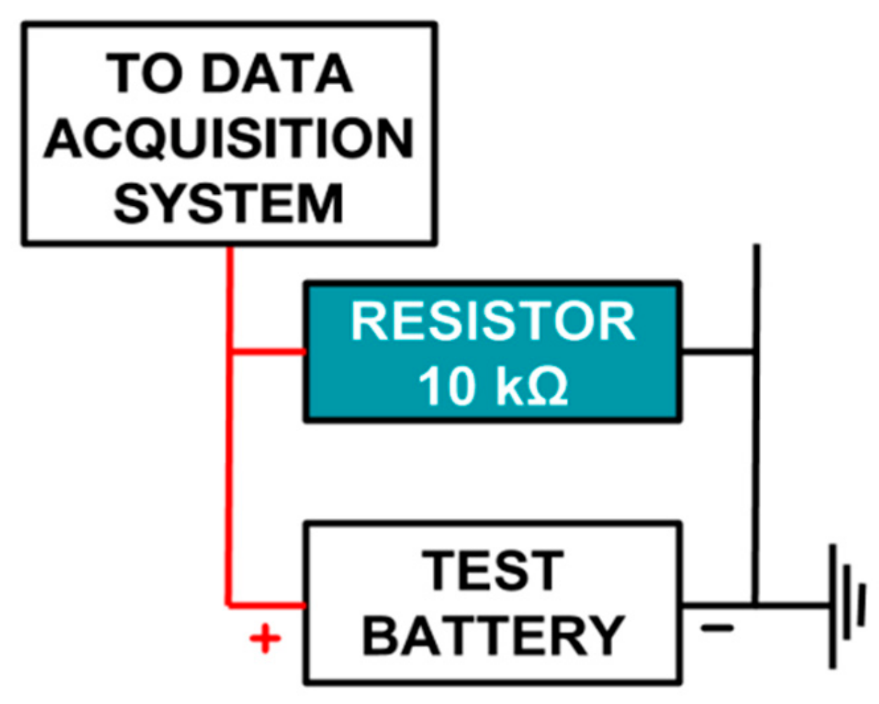
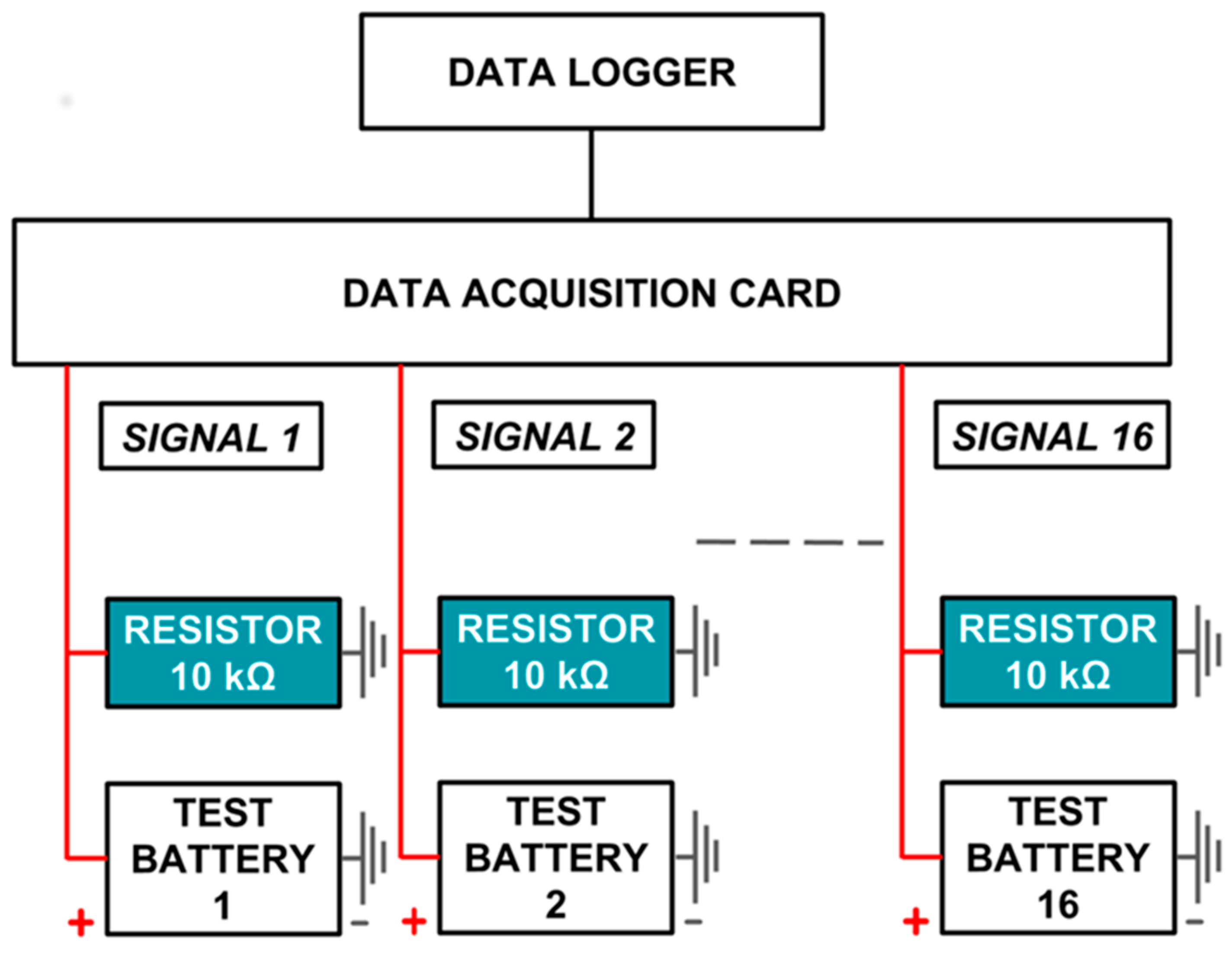
2.2. Data Acquisition System
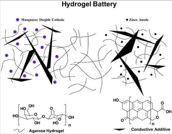
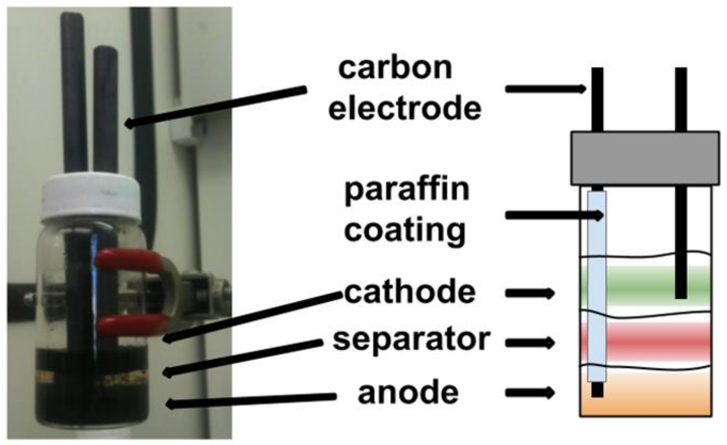
2.3. Gel Leclanché Cell Construction
2.4. Gel Leclanché Cells with Various Conductive Additives
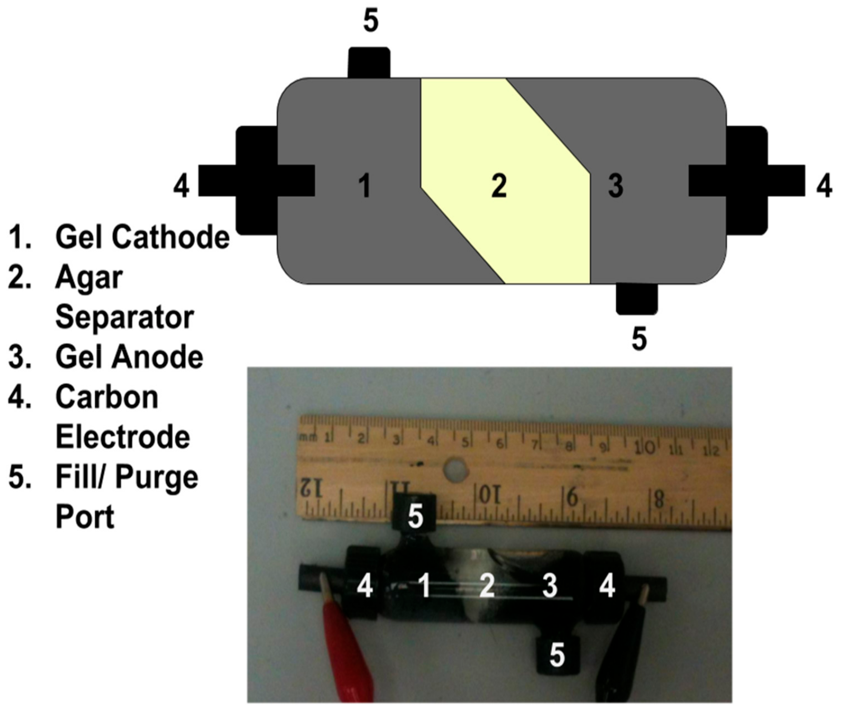
2.5. Closed Leclanché Gel Cell Construction and Purging
3. Results
3.1. Gel Leclanché Cell: Proof of Concept
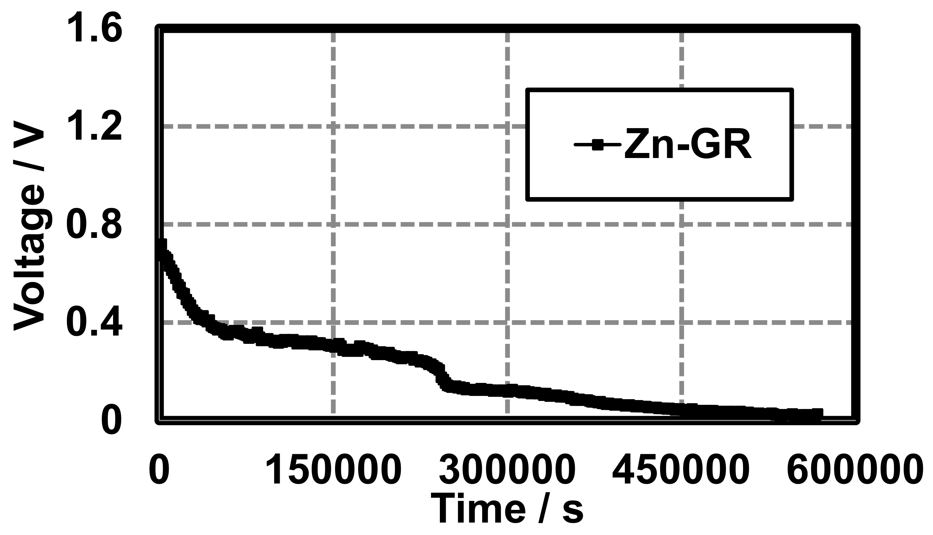
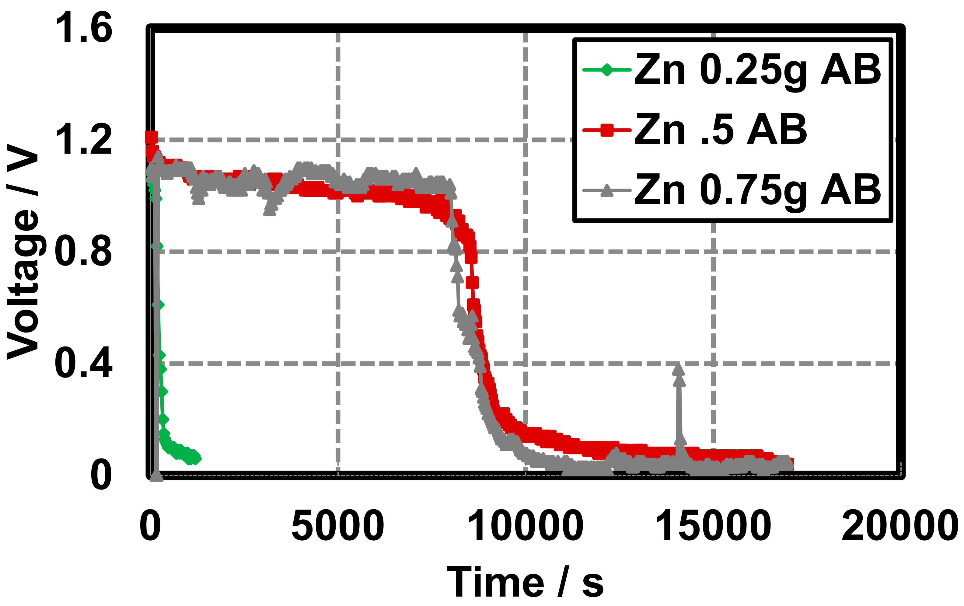
3.2. Different Conductive Additives
3.3. Cell Purge and Refill
4. Discussion
4.1. General Discharge Characteristics
4.2. Role of Active Material
4.3. Role of Conductive Additive
4.4. Purge and Refill
5. Conclusions and Future Work
Author Contributions
Funding
Acknowledgments
Conflicts of Interest
References
- Nicholls, M. Pioneers of cardiology: Rune Elmqvist, MD. Circulation 2007, 115. [Google Scholar] [CrossRef]
- Greatbatch, W. Origins of the implantable cardiac pacemaker. J. Cardiovasc. Nurs. 1991, 5, 80–85. [Google Scholar] [PubMed]
- Deforge, W. Cardiac pacemakers: A basic review of the history and current technology. J. Veter Cardiol. 2019, 22, 40–50. [Google Scholar] [CrossRef] [PubMed]
- Mallela, V.S.; Ilankumaran, V.; Rao, N.S. Trends in Cardiac Pacemaker Batteries. Indian Pacing Electrophysiol. J. 2004, 4, 201–212. [Google Scholar] [PubMed]
- Kotsakou, M.; Kioumis, I.; Lazaridis, G.; Pitsiou, G.; Lampaki, S.; Papaiwannou, A.; Karavergou, A.; Tsakiridis, K.; Katsikogiannis, N.; Karapantzos, I.; et al. Pacemaker insertion. Ann. Transl. Med. 2015, 3, 42. [Google Scholar] [CrossRef]
- Kindermann, M.; Schwaab, B.; Berg, M.; Frohlig, G. Longevity of dual chamber pacemakers: Device and patient related determinants. Pacing Clin. Electrophysiol. 2001, 24, 810–815. [Google Scholar] [CrossRef]
- Mond, H.G.; Freitag, G. The Cardiac Implantable Electronic Device Power Source: Evolution and Revolution. Pacing Clin. Electrophysiol. 2014, 37, 1728–1745. [Google Scholar] [CrossRef]
- Leclanché, G. Notes sur l’emploi des piles électriques en télégraphie, pile constante au peroxyde de manganeèse à un seul liquide; Impr. de Hennuyer et fils: Paris, France, 1867. [Google Scholar]
- Larcin, J. Chemical and Electrochemical Studies of Leclanché Cells. Ph.D. Thesis, Middlesex University, London, UK, 1991. [Google Scholar]
- Stimming, U.; Bele, P. Fuel Cells-Lots of Energy for 2016. Fuel Cells 2016, 16, 2. [Google Scholar] [CrossRef][Green Version]
- Stimming, U.; Bele, P. Further Ahead with Electrochemical Energy Technology. Fuel Cells 2017, 17, 2. [Google Scholar] [CrossRef][Green Version]
- Stimming, U.; Bele, P. Fuel Cells in a Changing Energy World. Fuel Cells 2018, 18, 3. [Google Scholar] [CrossRef]
- Linden, D.; Reddy, T.B. Linden’s Handbook of Batteries; McGraw-Hill: New York, NY, USA, 2001. [Google Scholar]
- Guo, Y.-G. Nanostructures and Nanomaterials for Batteries; Springer Science and Business Media: Berlin/Heidelberg, Germany, 2019. [Google Scholar]
- Khalid, N.; Ismail, Y.B.; Mohamad, A.A. ZnCl2− and NH4Cl− hydroponics gel electrolytes for zinc–carbon batteries. J. Power Sources 2008, 176, 393–395. [Google Scholar] [CrossRef]
- An, L.; Zhao, T.; Zhou, X.; Yan, X.; Jung, C. A low-cost, high-performance zinc–hydrogen peroxide fuel cell. J. Power Sources 2015, 275, 831–834. [Google Scholar] [CrossRef]
- Li, G.; Mezaal, M.A.; Zhang, R.; Zhang, K.; Lei, L. Electrochemical Performance of MnO2-based Air Cathodes for Zinc-air Batteries. Fuel Cells 2016, 16, 395–400. [Google Scholar] [CrossRef]
- Jensen, W.B. The Leclanché Cell. Notes from the Oesper Collections; University of Cincinnati: Cincinnati, OH, USA, 2014; Available online: http://www.che.uc.edu/jensen/W.%20B.%20Jensen/Museum%20Notes/24.%20The%20Leclanch%C3%A9%20Cell.pdf.
- Jenson, G.; Singh, G.; Bhama, J.K.; Ratner, A. A refillable hyrdogel battery: Construction and characterization. J. Energy Storage 2019, 23, 504–510. [Google Scholar] [CrossRef]
- Ahmed, E.M. Hydrogel: Preparation, characterization, and applications: A review. J. Adv. Res. 2013, 6, 105–121. [Google Scholar] [CrossRef]
- Zhang, X.; Kim, G.J.; Kang, M.G.; Lee, J.K.; Seo, J.W.; Tae, J.; Hong, K.; Cha, J.M.; Shin, S.R.; Bae, H. Marine Biomaterial-Based Bioinks for Generating 3D Printed Tissue Constructs. Mar. Drugs 2018, 16, 484. [Google Scholar] [CrossRef]
- Basu, P.; Saha, N.; Alexandrova, R.; Andonova-Lilova, B.; Georgieva, M.; Miloshev, G.; Saha, P. Biocompatibility and Biological Efficiency of Inorganic Calcium Filled Bacterial Cellulose Based Hydrogel Scaffolds for Bone Bioengineering. Int. J. Mol. Sci. 2018, 19, 3980. [Google Scholar] [CrossRef] [PubMed]
- Ahmad, N.; Colak, B.; Gibbs, M.J.; Zhang, D.-W.; Becer, C.R.; Watkinson, M.; Gautrot, J.E.; Krause, S. Collagenase Biosensor Based on the Degradation of Peptide Cross-Linked Poly(Ethylene Glycol) Hydrogel Films. Proceedings 2018, 2, 961. [Google Scholar] [CrossRef]
- Mittmann, E.; Gallus, S.; Bitterwolf, P.; Oelschlaeger, C.; Willenbacher, N.; Niemeyer, C.M.; Rabe, K.S. A Phenolic Acid Decarboxylase-Based All-Enzyme Hydrogel for Flow Reactor Technology. Micromachines 2019, 10, 795. [Google Scholar] [CrossRef]
- González-Martínez, A.; De Simón-Martín, M.; López, R.; Táboas-Fernández, R.; Bernardo-Sánchez, A. Remediation of Potential Toxic Elements from Wastes and Soils: Analysis and Energy Prospects. Sustainability 2019, 11, 3307. [Google Scholar] [CrossRef]
- Lu, J.; Zhang, X.; Gao, H.; Cui, W. Three-Dimensional Structure of PANI/CdS NRs-SiO2 Hydrogel for Photocatalytic Hydrogen Evolution with High Activity and Stability. Nanomaterials 2019, 9, 427. [Google Scholar] [CrossRef] [PubMed]
- Singh, R.; Veer, B. Hydrogels: Promising Energy Storage Materials. ChemistrySelect 2018, 3, 1309–1320. [Google Scholar] [CrossRef]
- Crulhas, B.R.; Ramos, N.P.; Basso, C.R.; Costa, V.E.; Castro, G.R.; Pedrosa, V.A. Fabrication and Characterization of Ferrocenece Containing Hydrogel for Glucose Biosensor Application. Int. J. Electrochem. Sci. 2014, 9, 7596–7604. [Google Scholar]
- Chen, M.; College of Chemistry and Environmental Engineering, Yangtze University. Microporous N-doped Carbon Electrochemical Catalyst Derived from Polyacrylamide Hydrogel for Oxygen Reduction Reaction in Alkaline Media. Int. J. Electrochem. Sci. 2018, 13, 2401–2411. [Google Scholar] [CrossRef]
- Rosi, M.; Iskandar, F.; Abdullah, M. Hydrogel-polymer electrolytes based on polyvinyl alcohol and hydroxyethylcellulose for supercapacitor applications. Int. J. Electrochem. Sci. 2014, 9, 4251–4256. [Google Scholar]
- Marliana, Y.; Ismail, B.; Haliman, H.; Mohamad, A.A. Hydroponics Polymer Gels for Zn-MnO2 Alkaline Batteries. Int. J. Electrochem. Sci. 2012, 7, 3555–3566. [Google Scholar]
- Mainar, A.R.; Iruin, E.; Colmenares, L.C.; Kvasha, A.; De Meatza, I.; Bengoechea, M.; Leonet, O.; Boyano, I.; Zhang, Z.; Blázquez, J.A. An overview of progress in electrolytes for secondary zinc-air batteries and other storage systems based on zinc. J. Energy Storage 2018, 15, 304–328. [Google Scholar] [CrossRef]
- Kim, J.-M.; Yoo, S.; Lim, J.-M.; Park, S.; Lee, S.-Y. Agarose-biofunctionalized, dual-electrospun heteronanofiber mats: Toward metal-ion chelating battery separator membranes. J. Mater. Chem. A 2015, 3, 10687–10692. [Google Scholar] [CrossRef]
- Armisen, R.; Galatas, F. Production and Utilization of Products from Commercial Seaweeds; McHugh, D.J., Ed.; FAO Fisheries Technical Report; FAO Fisheries: Rome, Italy, 1987. [Google Scholar]
- Arduino Reference. Available online: https://www.arduino.cc/ (accessed on 7 May 2019).
- Hawley, W.B.; Li, J. Electrode manufacturing for lithium-ion batteries—Analysis of current and next generation processing. J. Energy Storage 2019, 25. [Google Scholar] [CrossRef]
- American National Standard for Portable Primary Cells and Batteries with Aqueous Electrolyte-General and Specifications. Available online: https://www.batterybob.com/Battery-Reference/ansi_c18_1part1.pdf. (accessed on 22 January 2020).
- Rogulski, Z.; Czerwiński, A. Cathode modification in the Leclanché cell. J. Solid State Electrochem. 2003, 7, 118–121. [Google Scholar] [CrossRef]
- Bockris, J.O.; Conway, B.E.; Yeager, E.; White, R.E. Electrochemical Processing. In Comprehensive Treatise of Electrochemistry; Springer: Berlin/Heidelberg, Germany, 1981. [Google Scholar]
- Alkaline Manganese Dioxide Handbook and Application Manual, Energizer LLC. 2018. Available online: https://data.energizer.com/pdfs/alkaline_appman.pdf (accessed on 22 January 2020).
- Ghiurcan, G.A.; Liu, C.-C.; Webber, A.; Feddrix, F.H. Development and Characterization of a Thick-Film Printed Zinc-Alkaline Battery. J. Electrochem. Soc. 2003, 150, A922–A927. [Google Scholar] [CrossRef]
- Benson, G.; Gluck, J.; Kaufmann, C. Electrical Conductivity Measurements of Carbon Blacks. Trans. Electrochem. Soc. 1946, 90, 441. [Google Scholar] [CrossRef]
- Sebok, E.; Taylor, R.L. Carbon blacks. Encycl. Mater. Sci. Technol. 2001, 902–906. [Google Scholar] [CrossRef]
- Singh, G.; Esmaeilpour, M.; Ratner, A. The effect of acetylene black on droplet combustion and flame regime of petrodiesel and soy biodiesel. Fuel 2019, 246, 108–116. [Google Scholar] [CrossRef]
- Singh, G.; Lopes, E.; Hentges, N.; Becker, D.; Ratner, A. Experimental Investigation of the Settling Characteristics of Carbon and Metal Oxide Nanofuels. J. Nanofluids 2019, 8, 1–7. [Google Scholar] [CrossRef]
- Singh, G.; Esmaeilpour, M.; Ratner, A. Effect of carbon-based nanoparticles on the ignition, combustion and flame characteristics of crude oil droplets. arXiv 2019, arXiv:1910.12135. [Google Scholar]
- Celzard, A.; Marêché, J.; Payot, F.; Furdin, G. Electrical conductivity of carbonaceous powders. Carbon 2002, 40, 2801–2815. [Google Scholar] [CrossRef]
- Zhang, X.; Cui, Y.; Lv, Z.; Li, M.; Ma, S.; Cui, Z.; Kong, Q. Carbon nanotubes, Conductive Carbon Black and Graphite Powder Based Paste Electrodes. Int. J. Electrochem. Sci. 2011, 6, 6063–6073. [Google Scholar]
- Marinho, B.; Ghislandi, M.; Tkalya, E.; Koning, C.E.; De With, G. Electrical conductivity of compacts of graphene, multi-wall carbon nanotubes, carbon black, and graphite powder. Powder Technol. 2012, 221, 351–358. [Google Scholar] [CrossRef]
- Du, Z.; Li, J.; Wood, M.; Mao, C.; Daniel, C.; Wood, D. Three-dimensional conductive network formed by carbon nanotubes in aqueous processed NMC electrode. Electrochim. Acta 2018, 270, 54–61. [Google Scholar] [CrossRef]
- Tsai, H.-L.; Hsieh, C.-T.; Li, J.; Gandomi, Y.A. Enabling high rate charge and discharge capability, low internal resistance, and excellent cycleability for Li-ion batteries utilizing graphene additives. Electrochim. Acta 2018, 273, 200–207. [Google Scholar] [CrossRef]
- Li, J.; Armstrong, B.L.; Daniel, C.; Kiggans, J.; Wood, D.L.; Kiggans, J. Optimization of multicomponent aqueous suspensions of lithium iron phosphate (LiFePO4) nanoparticles and carbon black for lithium-ion battery cathodes. J. Colloid Interface Sci. 2013, 405, 118–124. [Google Scholar] [CrossRef] [PubMed]


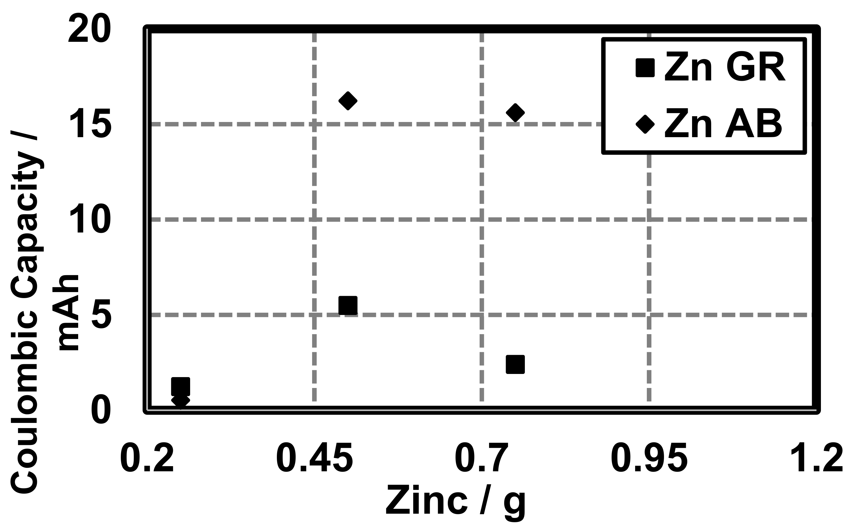
 ), 0.5 g (
 ), and 0.75 g (
 ).
), 0.5 g (), and 0.75 g ().
).
), 0.5 g (), and 0.75 g ().
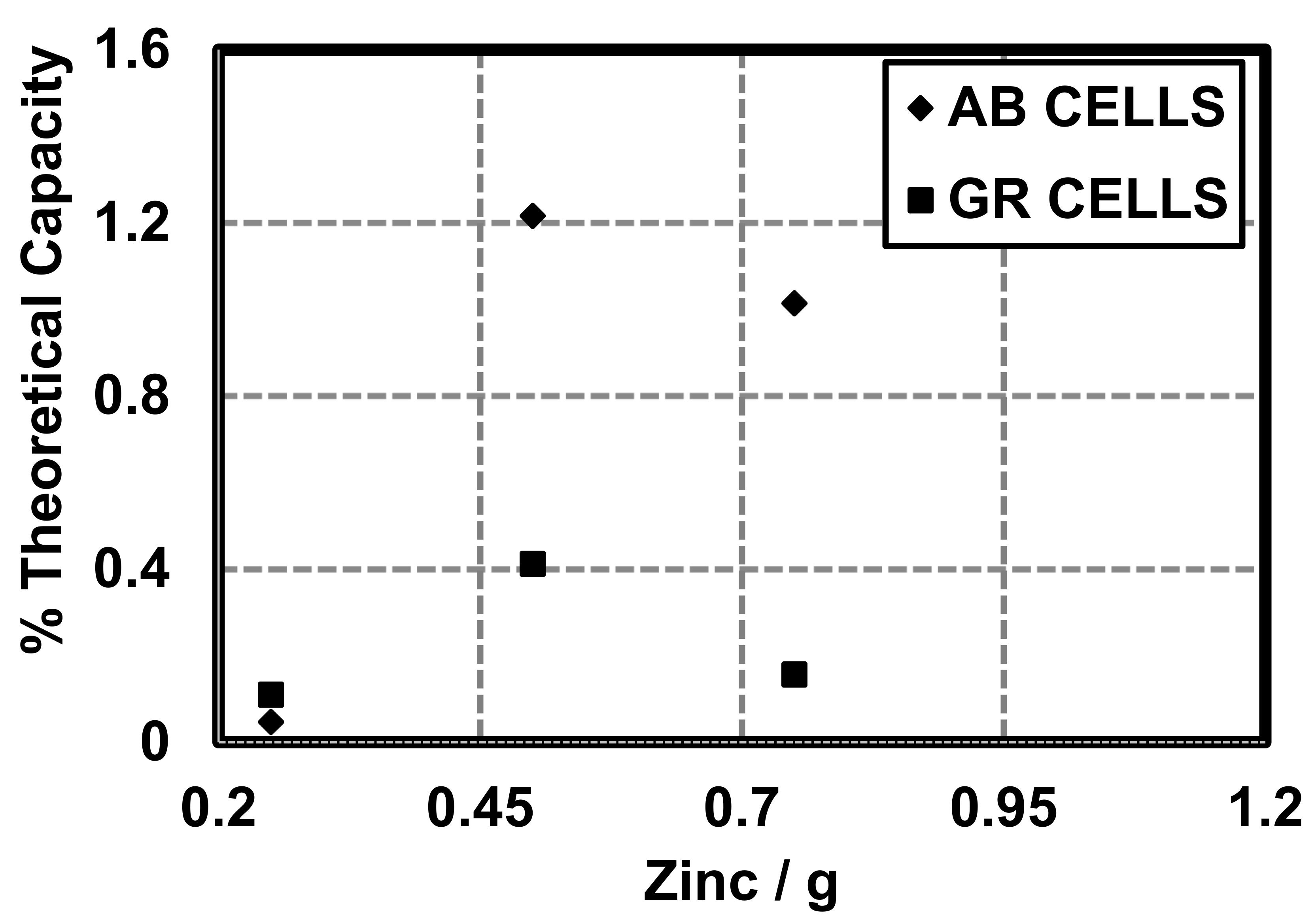
 ), 0.5 g (
 ), and 0.75 g (
 ).
), 0.5 g (), and 0.75 g ().
).
), 0.5 g (), and 0.75 g ().


© 2020 by the authors. Licensee MDPI, Basel, Switzerland. This article is an open access article distributed under the terms and conditions of the Creative Commons Attribution (CC BY) license (http://creativecommons.org/licenses/by/4.0/).
Share and Cite
Jenson, G.; Singh, G.; Bhama, J.K.; Ratner, A. Hydrogel Leclanché Cell: Construction and Characterization. Energies 2020, 13, 594. https://doi.org/10.3390/en13030594
Jenson G, Singh G, Bhama JK, Ratner A. Hydrogel Leclanché Cell: Construction and Characterization. Energies. 2020; 13(3):594. https://doi.org/10.3390/en13030594
Chicago/Turabian StyleJenson, Greg, Gurjap Singh, Jay K. Bhama, and Albert Ratner. 2020. "Hydrogel Leclanché Cell: Construction and Characterization" Energies 13, no. 3: 594. https://doi.org/10.3390/en13030594
APA StyleJenson, G., Singh, G., Bhama, J. K., & Ratner, A. (2020). Hydrogel Leclanché Cell: Construction and Characterization. Energies, 13(3), 594. https://doi.org/10.3390/en13030594