Article

Numerical Study on Novel Design for Compact Parallel-Flow Heat Exchanger with Manifolds to Improve Flow Characteristics

1
Regional Leading Research Center, Changwon National University, Changwon 51140, Korea
2
Department of Aerospace Engineering, Pusan National University, Busan 46241, Korea
3
Department of Mechanical Engineering, Changwon National University, Changwon 51140, Korea
*
Authors to whom correspondence should be addressed.
Energies 2020, 13(23), 6330; https://doi.org/10.3390/en13236330
Submission received: 7 October 2020 / Revised: 10 November 2020 / Accepted: 26 November 2020 / Published: 30 November 2020
(This article belongs to the Special Issue Heat Exchangers: Cooling and Heating Systems)

Abstract

:
Parallel flow heat exchangers with manifolds are widely used in various industries owing to their compact size and ease of application. Research has been conducted to understand their flow characteristics and improve flow distribution and pressure drop performance; however, it is difficult to derive generalized improvements under different conditions for each application. This study proposes a novel design to improve the flow characteristics of a compact heat exchanger with a sudden expansion area of a dividing manifold and uses computational fluid dynamics simulation to verify it. The abrupt cross-sectional area change in the dividing manifold induces a jet flow near the entry region, which causes the flow maldistribution of the first few parallel tubes. To improve the efficiency of the dividing manifold, simple and novel designs with a converging-diverging area in the manifold header have been proposed. Parametric studies on the novel designs show improvements of up to 37.5% and 52.0% flow uniformity and 2.65% and 0.74% pressure drop performance for U- and Z-types, respectively, compared to the base model. Thus, the simple and easily fabricated quadrilateral shape can improve the flow maldistribution and pressure drop caused by a dividing manifold with a sudden area expansion.

1. Introduction

Compact parallel-flow heat exchangers with manifolds, such as boilers, condensers, solar energy collectors, and multi-pipe earth-to-air heat exchangers, have been widely used in industrial fields for heating or cooling. Typically, they are composed of multiple manifolds and parallel tubes, and the manifolds are classified into dividing and combining flow manifolds. A dividing manifold receives fluid through a single inlet and distributes the fluid through multiple exits; a combining manifold receives fluid through multiple inlets and discharges the fluid through a single exit.
Uniform flow distribution in parallel-flow heat exchangers is important in the system operation of process engineering for obtaining a higher heat exchange performance and a lower pressure drop. To achieve this goal, the fluid pressure must remain constant based on the system requirements. Therefore, an appropriate manifold design must be selected to achieve a uniform flow distribution with a minimum pressure drop in the system.
Many researchers have studied parallel-flow heat exchangers with manifolds. Early studies investigated flows experimentally and analytically to understand flow physics. Acrivos et al. [1] proposed one-dimensional calculation models for manifold flow distribution. The prediction results were in accordance with the observed flow patterns in most cases. Kubo and Ueda [2] suggested formulas for calculating the flow rate ratio of each branch pipe. The formulas were experimentally verified using water over a wide range of Reynolds numbers and branch pipe resistances with orifice plates of different sizes. Bajura and Jones [3] studied the flow distribution in manifolds both analytically and experimentally. They predicted the flow rates and pressures in headers and compared the analytical and experimental results obtained. Subsequently, they proposed an analysis method for general applications to evaluate the performance of flow distribution systems.
Another group attempted to numerically achieve a uniform flow distribution using computational fluid dynamics (CFD). Choi et al. [4] investigated the laminar flow distribution in the manifolds of liquid cooling modules. They reported that the distribution curves were strongly affected by the area ratio, thereby affecting the performance of the heat exchanger. Wang et al. [5,6] studied single-phase distributions in a parallel flow heat exchanger through experimental and numerical investigations. They reported that the flow distribution for the U-type flow is more uniform than that for the Z-type flow, with a small deviation in flow uniformity between experiments and simulations. Furthermore, they experimentally compared typical dividing manifold designs with five different modifications of the inlet header. They studied the dependency on the header shape and flow rate for the flow distribution and obtained an average flow ratio close to 0.111 with a baffle with multiple sized holes. Gandhi et al. [7] studied the flow and pressure distributions in a pipeline network. They performed extensive investigations using CFD to obtain a uniform flow distribution, demonstrating that the uniformity in the distribution is a unique function of the distributor geometry and inlet kinetic energy. They concluded that the tube diameter, number of tubes, and locational arrangement with respect to inlet and outlet are the most important design parameters. Huang and Wang [8] conducted Z-type compact parallel flow heat exchanger optimization with the Levenberg–Marquardt method and CFD. They selected the diameter of the tubes and entrance length as design parameters to obtain the desired uniform flow distribution. Tong et al. [9] investigated manifold design strategies to achieve the same rate of mass outflow through each of the exit ports of a distribution manifold with two-dimensional numerical simulation. They concluded that the four most promising strategies are enlargement, variation, linear, and non-linear tapering of the cross-sectional area of the distribution method.
Although numerous studies have been performed to understand the flow characteristics of parallel-flow heat exchangers, a solid methodology for the optimum design of a manifold system with multiple branches has not been proposed yet. From the aforementioned studies, the contributions to improve flow uniformity can be summarized as follows:
  • Studies on the effects of major shape dimensions such as tube diameter, length, and number of tubes;
  • Development of several designs of reduced cross-section along the flow path in the inlet header;
  • Use of baffle plates or tubes with different-sized holes along the dividing manifold.
Parallel heat exchangers with manifolds for flow distributions are typically used for systems of compact sizes, such as cooling devices for electronics and fuel cell stacks [4,10]. The manifold design can be very important in such compact systems to achieve better performance in terms of uniform flow distribution and moderate pressure drop compared to large heat exchangers [11]. Applying complex geometries to achieve flow uniformity in a confined space can create difficulties in manufacturing and result in increased pressure loss.
The objective of this study is to propose simple and novel designs and investigate their effects on flow characteristics through numerical simulation. The novel designs are aimed at controlling the local pressure distribution with a small converging and diverging shape in a small dividing manifold with a sudden area expansion inlet.

2. Geometrical Details and Numerical Methods

2.1. Model Description

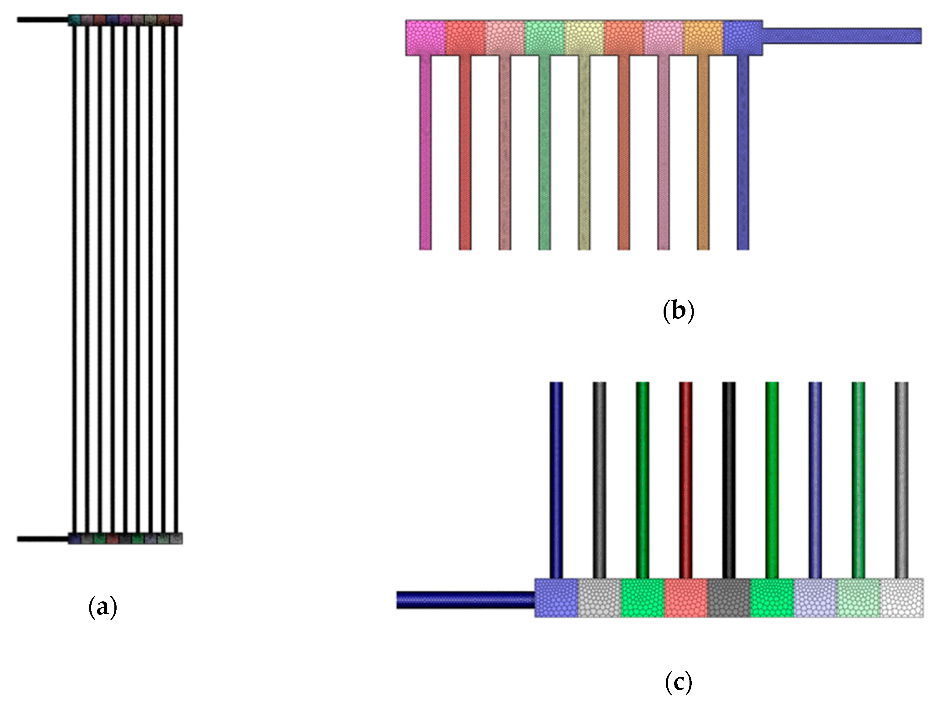
The benchmark test model discussed in this study is referenced from the model of Wang et al. [5,6]. Schematic of conventional U- and Z-types parallel flow heat exchangers with manifolds are presented in Figure 1.
The system is composed of nine tubes and two combining and dividing manifolds. The tube nearest to the inlet was assigned as the first tube. The tube length was 400 mm, and the cross-section of the manifold was 9 mm × 9 mm. The manifolds had circular inlet and outlet tubes located below the centerline of the square header. The geometric details are provided in Table 1.

2.2. Governing Equations and Model Assumption

The governing equations were the continuity equation for the conservation of mass and the Navier–Stokes equation for the conservation of momentum:
· u = 0 ,
ρ u t + ρ u · u = p + μ 2 u ρ g ,
where u is the fluid velocity vector [m/s],   ρ is the coolant density [kg/m3], p is the pressure [Pa], μ is the dynamic viscosity [Pa s], and g is the gravitational acceleration [m2/s].
Simulations were performed using the commercial CFD code FLUENT with E5-2620 2.0 GHz CPU 24 cores and 32 GB DDR3 RAM. It solves fully implicit conservation equations for a turbulent flow based on the Reynolds-averaged Navier–Stokes approach [12].
In this study, water was used as the working fluid, and numerical simulations were conducted based on the following assumptions:
  • No phase change or heat transfer occurs inside the compact heat exchangers;
  • The density variation is disregarded, and the flow is considered incompressible.
The boundary conditions were an inlet mass flow rate of 11 pm and a pressure outlet at the exit of the computational domain. The symmetric condition along the z-axis was used to reduce the computational resources for the full domain, and the no-slip condition was specified for the solid walls.
All the solutions were considered to converge when the residual was below 1 × 10⁻⁵, and the time-history of the mass flow rates remained variable in the specific channel.
To evaluate the flow distribution among the parallel tubes of a heat exchanger, two dimensionless variables were introduced, as follows:
β i = Q i Q ,
where β i and Q i represent the flow ratio and volume flow rate in the ith tube (m3/s), respectively; Q is the total volume flow rate (m3/s) [5,8].
The dimensionless standard deviation of the flow ratio was used to estimate the uniformity, Φ , as this is a measure of the variation of a set of values:
Φ = i = 1 N ( β i β ¯ ) 2 N ,
where N is the total number of tubes in the parallel flow heat exchangers, and β ¯ is the average flow ratio defined as β ¯ = i = 1 N β i N [5,8]. A lower value of Φ represents a uniform flow distribution in the system.

2.3. Grid Dependence

To determine the reliability of the simulation results, grid analysis was conducted in the target domain. Polyhedral mesh elements were generated, as shown in Figure 2. Compared with hexahedral and tetrahedral meshes, polyhedral mesh elements are rapidly and semi-automatically generated, with low numerical diffusion.
The flow uniformity index was compared for seven different mesh numbers. Figure 3 shows the results of the grid-dependence study.
As the number of nodes increased, the flow non-uniformity index converged. Subsequently, the appropriate number of nodes (2.14 M) was selected.

2.4. Model Validation

To accurately predict the fluid flow and pressure distribution in a system, the present CFD model must be validated. Experimental data from Wang et al. [5] and Huang and Wang [8] were used for model validation.
The turbulence model used in CFD for predicting the performance of flow characteristics in parallel-flow was presented with realizable k-ε and renormalized group k-ε [13,14]. However, Menter [15] reported that the shear stress transport (SST) model is an improved model for all flows, with adverse pressure gradients compared with other eddy viscosity models. Therefore, it was used in this study. The SST model offers the advantages of the k-ε and k-ω models with a blending function. The k-ω model was used in the near-wall region, whereas the k-ε model was adapted in the region far from the wall. The Y+ value for the first grid from the wall was less than 1.
Single-phase CFD simulations were conducted under steady-state conditions, and the validation results are provided in Table 2.
A good agreement on the flow uniformity index was achieved between the experimental and the CFD simulation results.

3. Novel Design and Parameter Study

Although geometrical variations of manifolds to improve the flow uniformity and pressure drop in a system have been proposed, they are not sufficient to satisfy all the requirements of the manufacturing method, cost, and feasibility. In this study, a novel quadrilateral shape is proposed to improve the flow distribution considering manufacturing convenience.
The schematic and associated design parameters are shown in Figure 4. A simple quadrilateral shape based on the converging and diverging geometry was used to compensate for the local pressure drop near the entry region in a dividing manifold owing to the sudden expansion of the cross-sectional areas. When the flow enters a sudden expansion region at the inlet, a single jet flow is induced. Therefore, the flow rates of the tubes nearest to the entry region significantly decrease. A quadrilateral shape participates in recovering the pressure by reducing the cross-sectional area near the first tube of the header.
The length, height, and installation location in the inlet region of the header were set as the major parameters of the quadrilateral shape. This selection was based on the flow maldistribution near the entry region due to the jet effect in the sudden expansion of the cross-sectional area. The parameters for each quadrilateral shape are listed in Table 3.

4. Results and Discussion

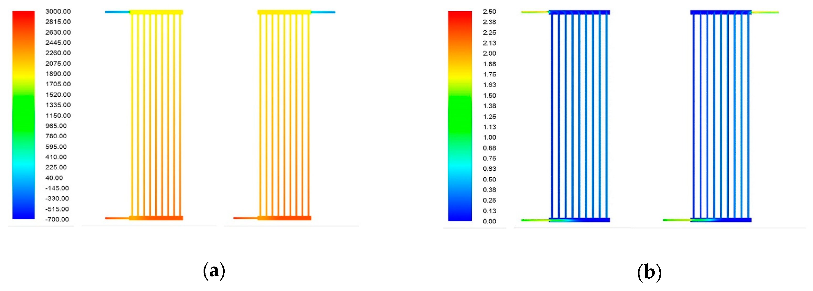
Figure 5a shows the static pressure contours in the base model of the U- and Z-type parallel-flow heat exchangers. As the flow passed along the inlet header, the pressure increased. The pressure near the inlet was relatively low, which caused a flow imbalance in the first few tubes from the entry. As seen in Figure 5b, the jet flow was dominant at the entrance owing to the sudden area expansion. The first few tubes indicated the lowest velocity distribution owing to the low pressure. The jet penetration length was the same for both cases; however, for the Z-type, the direction of the jet gradually changed toward the connected tube.
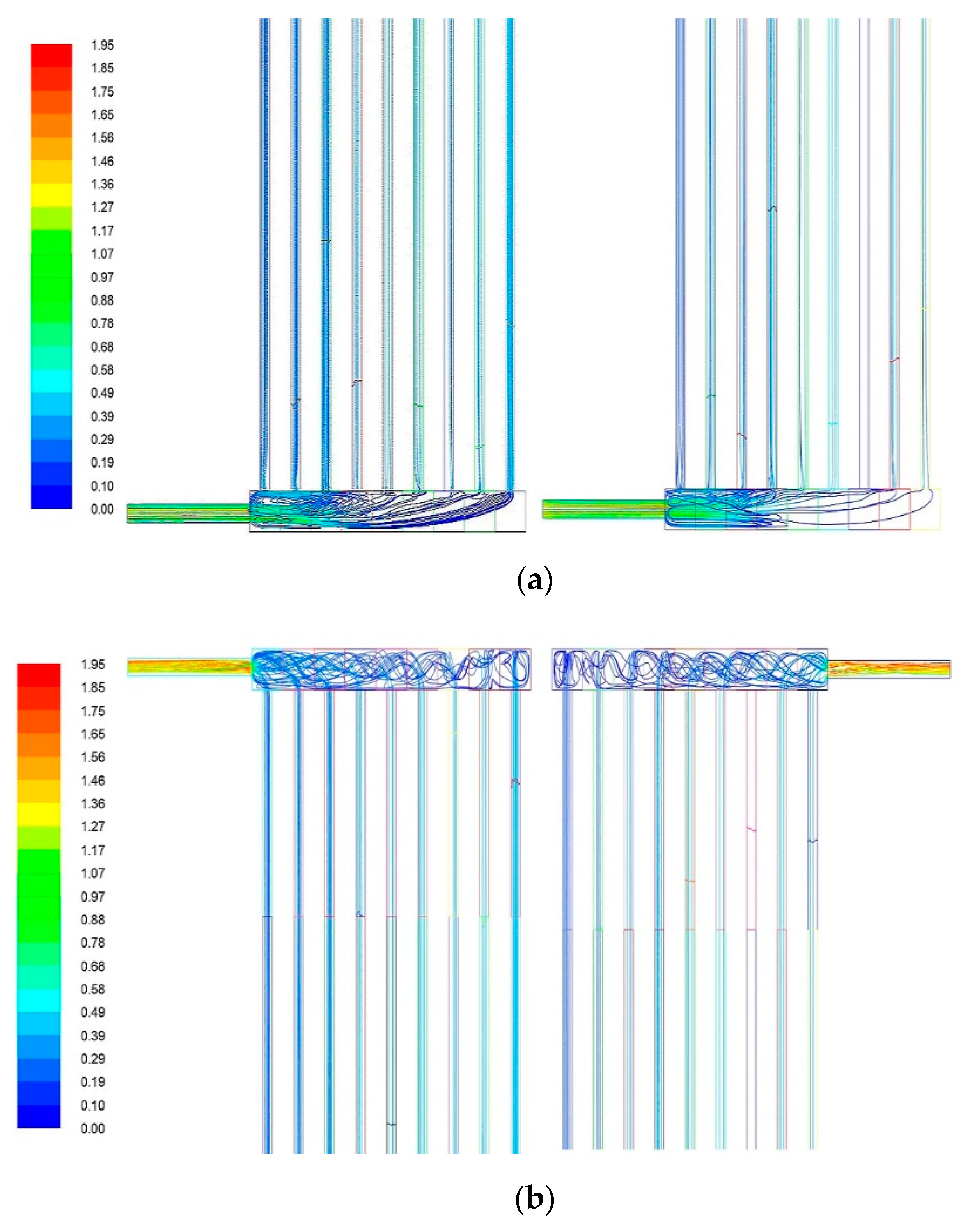
For these phenomena, the flow characteristics were evident from the velocity streamline, as shown in Figure 6. As the jet flow induced by the sudden area expansion entered the header of the dividing manifold, a vortex flow occurred during fluid mixing. This caused a lower flow rate in the first few tubes located near the entry region. In the case of the flow outlet, there was no noticeable difference between the two cases, as the combined manifold has a sudden area contraction limiting the flow control. From these basic results, we can conclude that flow maldistribution is inevitable for structures with a sudden area change, and flow control must be performed in the dividing manifold to improve the flow characteristics.
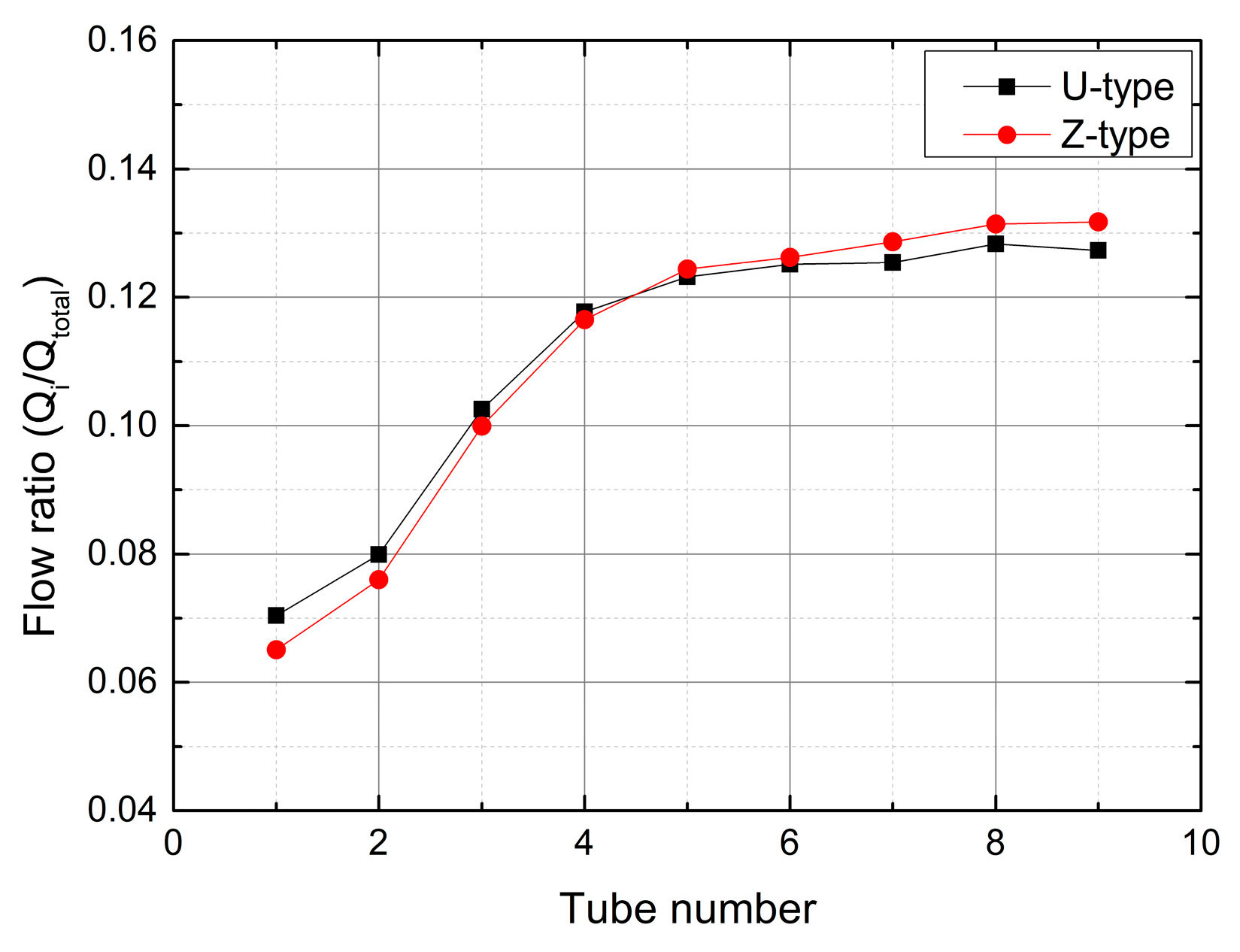
The flow distribution of each tube in Figure 7 indicates that the overall distribution is more uniform in the U-type than in the Z-type. This result is in accordance with previous research [5], and the same conclusion is also derived in the research on earth-to-air heat exchangers [14]. The flow distribution in the first tube closest to the inlet deviates approximately 36.6% and 41.4% from the ideal value for U- and Z-types, respectively. In addition, the steepest gradient exists from the first to the fourth tube in a dividing manifold, which means that the flow maldistribution depends on the jet caused by a sudden area expansion.
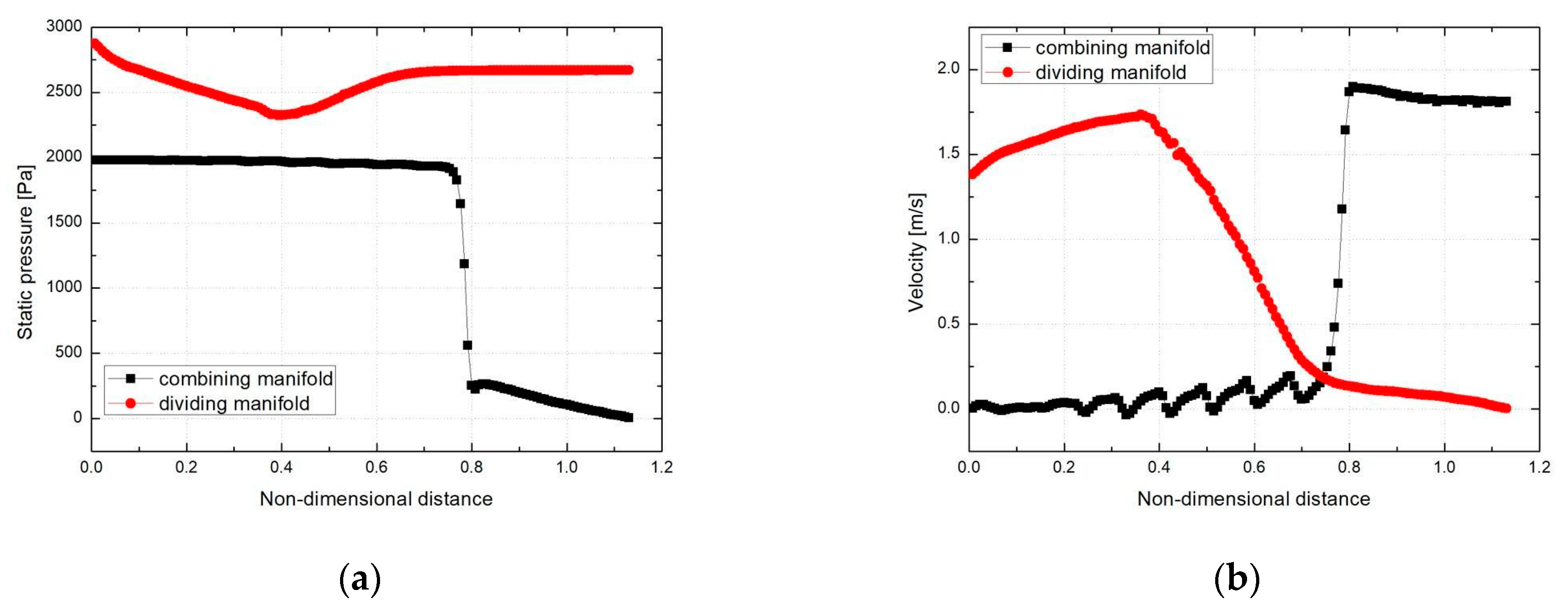
Figure 8 shows the pressure and velocity distribution along the flow axis of the U-type manifolds. As the fluid flowed along the flow axis in the dividing manifold, the pressure decreased with the acceleration of the fluid in the inlet circular tube. When the fluid entered the header of the dividing manifold, its velocity rapidly decreased through the flow mixing. The static pressure was the lowest near the first tube after the sudden area expansion, which yielded the lowest pressure difference between the dividing and combining manifolds. Consequently, flow maldistribution was more intense in the first tube and gradually recovered along the flow path.
The pressure and velocity distributions along the flow axis of the Z-type manifolds are shown in Figure 9. The issues encountered were the same as those in the U-type manifolds.
The benchmark test result indicates that when a sudden cross-sectional change occurs in the manifolds of a compact parallel-flow heat exchanger, a flow maldistribution occurs in the first few tubes near the entry region. Therefore, the flow maldistribution must be improved using the dividing manifold near the entry region because the effect of flow control in the outlet region is restricted by the sudden contraction area.
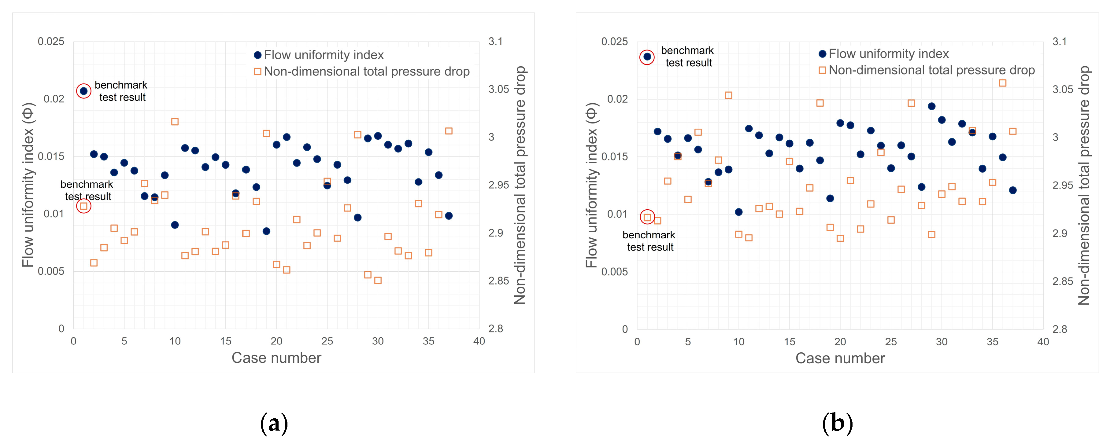
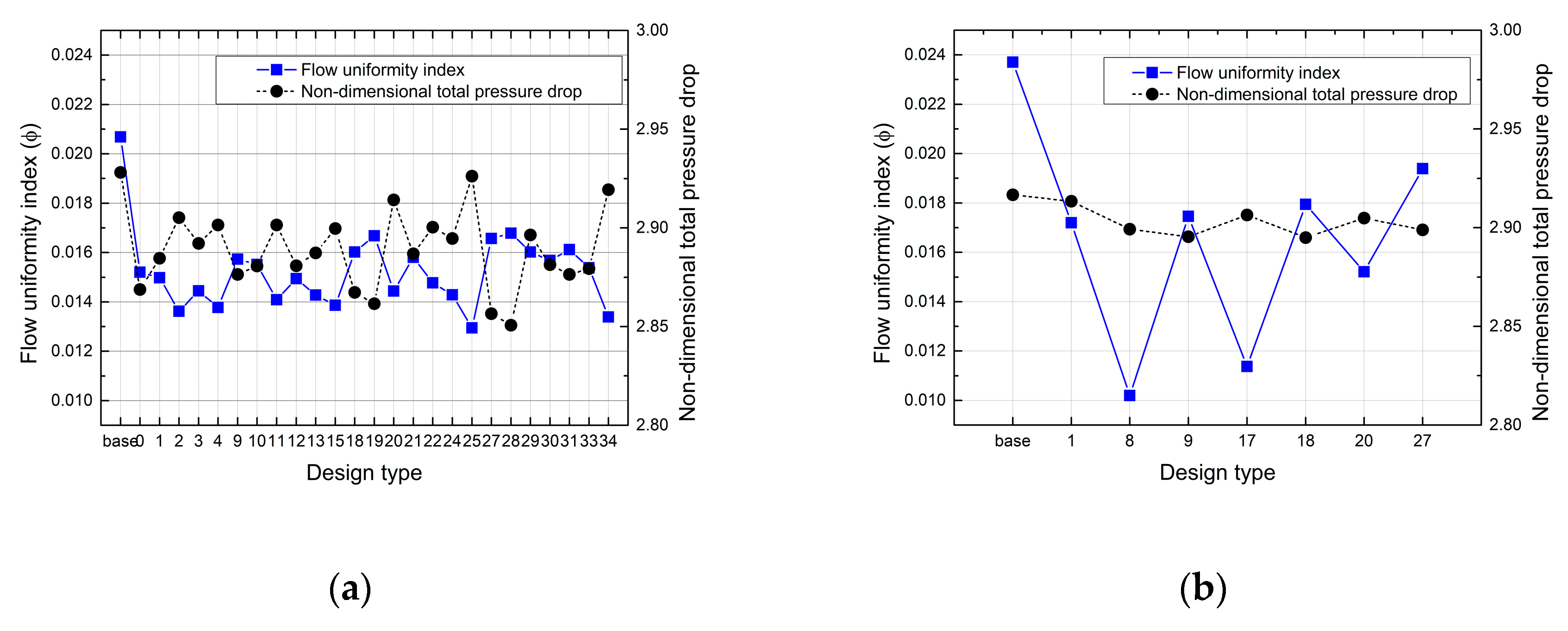
The primary focus of novel designs is to improve the flow maldistribution near the entry region. Figure 10 shows the effect of each shape on the flow uniformity and total pressure difference compared with the U- and Z-types benchmark test results. In terms of flow uniformity, the ideal flow ratio for each tube should be approximately 0.111. The pressure drop across the system must be minimized to obtain the objective of a novel design. For both the U- and Z-type manifolds, their flow uniformities were improved by adapting quadrilateral shapes in the dividing manifold. However, the pressure drop was dependent on each parameter, particularly the height of the quadrilateral shape.
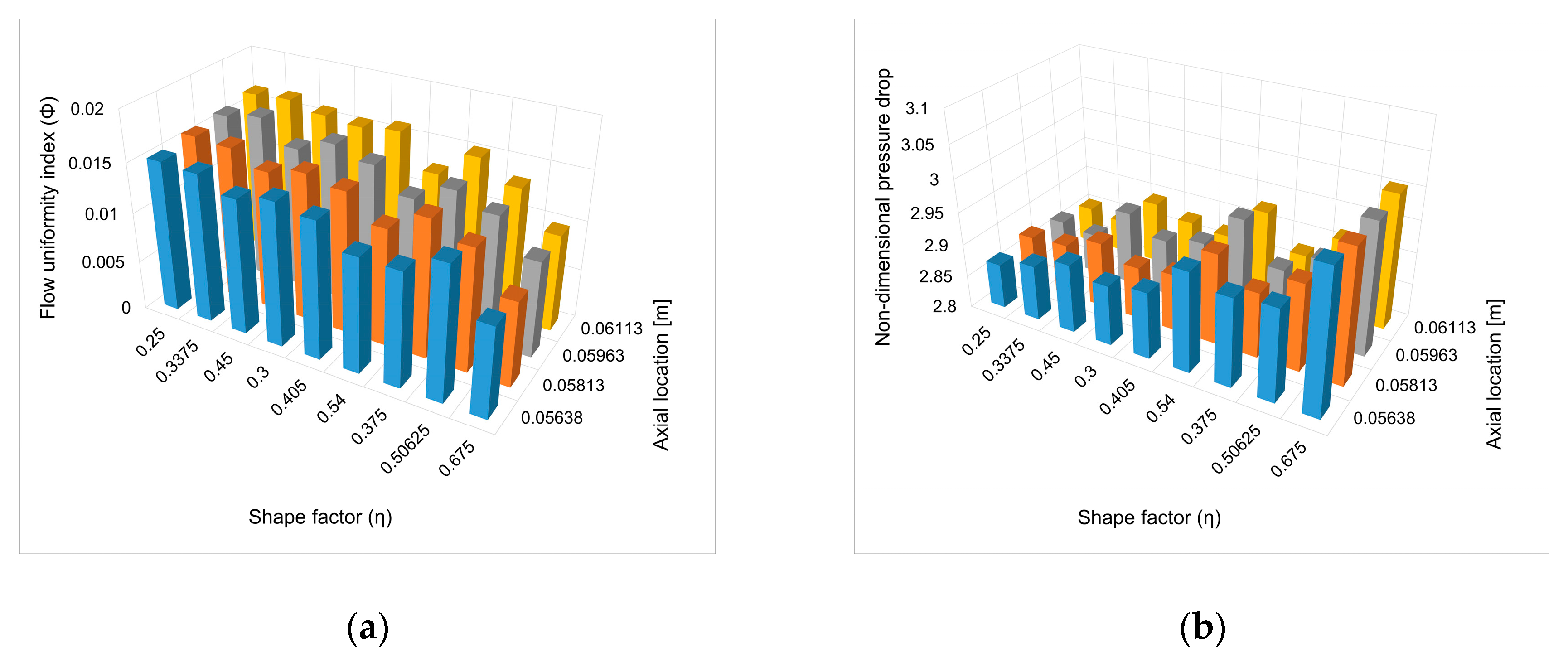
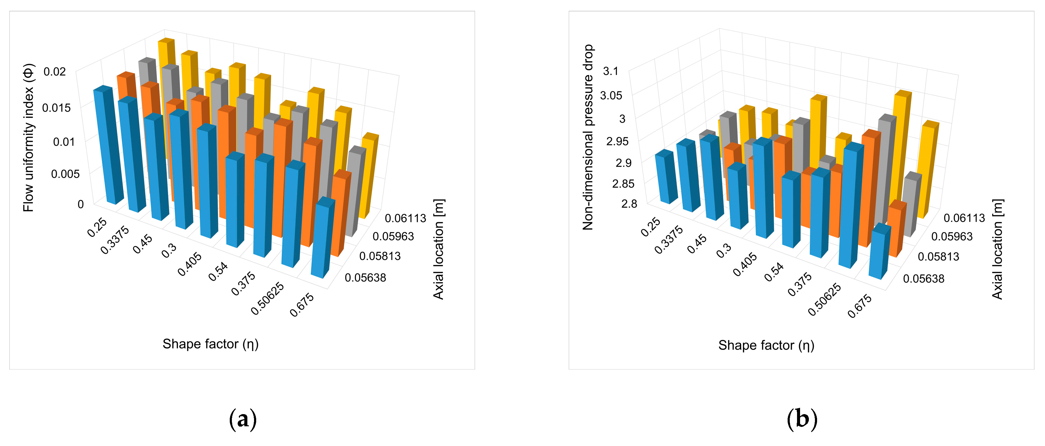
To investigate the correlation between the design parameters, flow uniformity, and pressure drop, the shape factor was defined as the height-to-length of the quadrilateral shape, reducing the three parameters to two. Figure 11 and Figure 12 show the results of correlations between the shape factor, axial installation location, and flow characteristics of the flow uniformity and pressure drop.
The flow uniformity decreases as the shape factor decreases and the axial installation location becomes farther from the entry region. If the shape factor increases, the pressure drop also increases. These results are identical for both the U- and Z-type manifolds, as shown in Figure 11 and Figure 12, respectively.
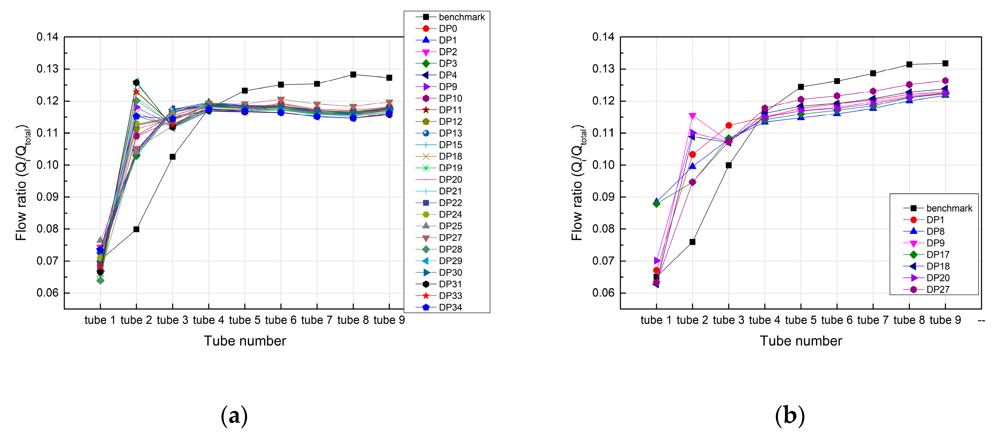
As mentioned earlier, compared to the base model, novel designs yielded improved results for all design parameters in terms of flow uniformity. However, there were cases for which the non-dimensional total pressure drop increased. Figure 13 shows the cases where the flow characteristics in novel designs are better than those in the base model. According to the results, the flow uniformity index improved up to 37.46% and 52.00%, and the non-dimensional total pressure drop improved up to 2.65% and 0.74% for the U- and Z-types, respectively.
The flow distribution of each tube for the U- and Z-types is presented in Figure 14. The flow distribution of novel designs is significantly improved compared to the base model, shown in black in each figure. The base model tends to be non-uniform from the first to the third tube, but novel designs improve uniformity depending on the design conditions. It can be seen that the U-type is more effective than the Z-type under the same conditions.
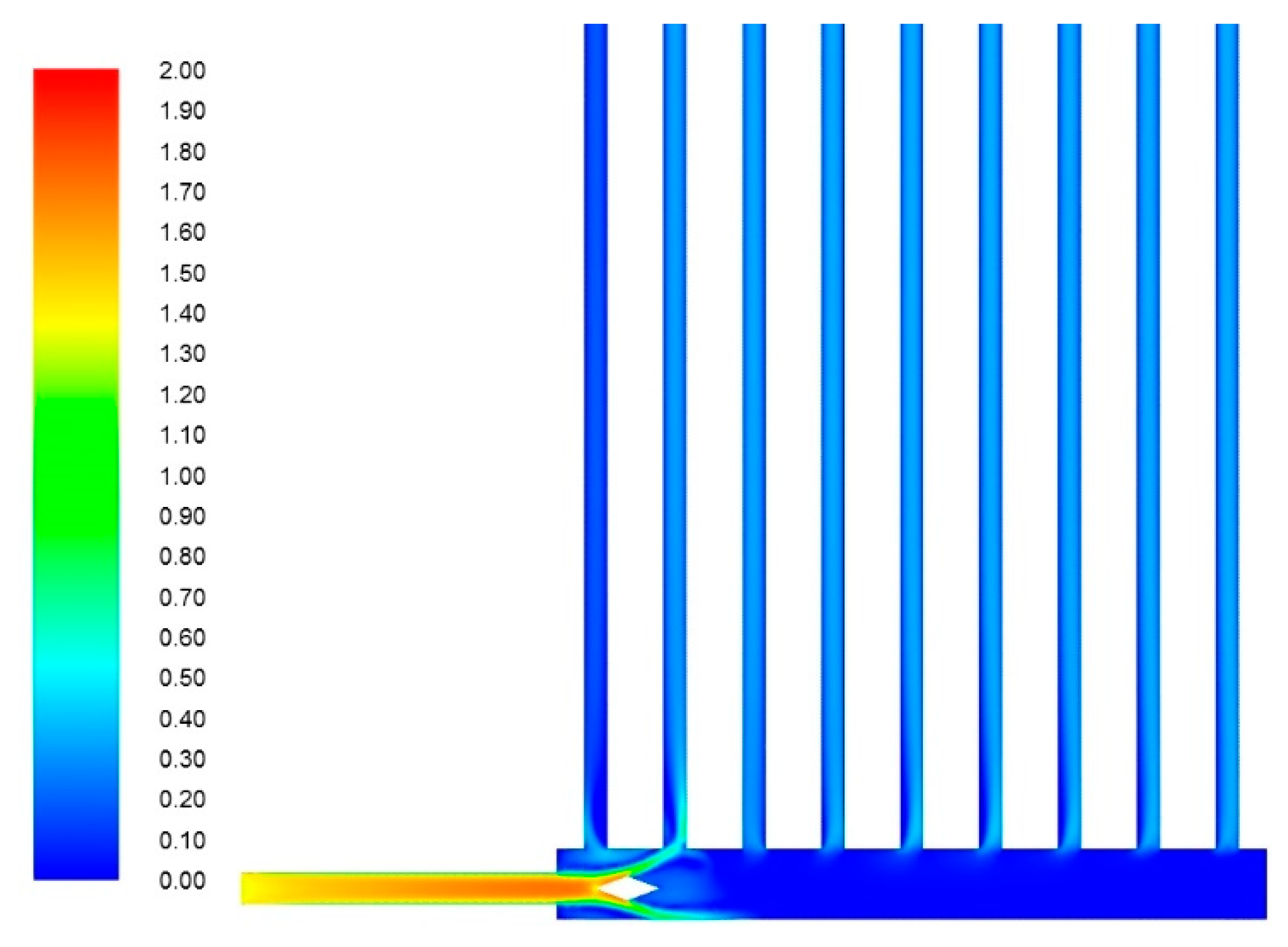
A peak value appeared in the second tube for some design parameters, which may have been caused by a flowing stream directly toward the second tube. To observe this, the velocity distribution of a sample case among various design parameters is shown in Figure 15. In the base model, the effect of the jet at the inlet almost reaches the fourth tube, but in novel designs, the effect is quickly dissipated by the quadrilateral shape.
Although the flow distribution and pressure drop in the system have considerably improved, it is difficult to derive a generalized correlation among the design parameters based on the results mentioned. This study suggests novel designs to improve the flow characteristics with minimal change in the shape of the dividing manifold, but further research is required to determine the optimized shape among design parameters. To this end, we plan to conduct shape optimization with two objective functions: flow uniformity and pressure drop, and manufacturability through 3D metal printing.

5. Conclusions

A novel design to improve flow uniformity and pressure drop in compact U- and Z-type parallel-flow heat exchangers with a sudden area expansion was proposed and investigated via numerical simulation. The main geometrical features of the base model are a manifold cross-section of 9 mm × 9 mm and a length of 90 mm, inlet and outlet tube diameters of 4 mm, parallel tube diameters of 3 mm, and length of 400 mm. The results are summarized as follows:
  • When there was a sudden expansion of the cross-sectional area at the inlet of the dividing manifold, a jet flow was induced. This jet flow caused a certain level of flow maldistribution near the entry region owing to the lowest pressure difference between the dividing and combining manifolds.
  • A novel design was proposed by combining converging and diverging cross-sectional areas along the dividing manifold. This shape improved the flow uniformity and pressure drop in a system with minimum geometry change, as suggested by other researchers. For U- and Z-types, the flow uniformity index ( Φ ) improved up to 37.46% and 52.00%, respectively, and the non-dimensional total pressure drop improved up to 2.65% and 0.74%, respectively. The worst flow distribution was observed in the first tube; when the novel design was applied, the values of the flow distribution ( β i ) in the U- and Z-types improved up to 8.60% and 39.95%, respectively.
  • The volume flow was 1 lpm of water, equivalent to Re = 5780 based on the inlet tube, thus making it difficult to draw a generalized conclusion. However, as the flow rate increases, it can be predicted that the flow maldistribution will increase due to the change in the jet penetration length at the inlet and the increase in the pressure inside manifolds.
  • To obtain the correlation among the parameters of the novel designs, analyses were conducted. As the flow shape factor decreased and the axial installation location moved away from the inlet, the flow uniformity deteriorated. Moreover, as the shape factor increased, the pressure drop also increased. According to the results, some correlations among parameters to improve the characteristics of the system were derived, but the optimized design factors were unclear. Therefore, further consideration will be given to the optimal shape based on objective functions of the flow uniformity index and pressure loss and the manufacturability through 3D metal printing. This will be explored in future research.

Author Contributions

Conceptualization, B.K. and K.K.; methodology, K.K.; software, B.K.; validation, B.K., K.K., and S.K.; writing—original draft preparation, B.K.; writing—review and editing, B.K. and S.K.; supervision, K.K. and S.K.; funding acquisition, S.K. All authors have read and agreed to the published version of the manuscript.

Funding

This work was supported by the National Research Foundation of Korea (NRF) grant funded by the Korean government (MSIP) through the Regional Leading Research Center (No. 2019R1A5A80832012).

Conflicts of Interest

The authors declare no conflict of interest.

References

  1. Acrivos, A.; Babcock, B.D.; Pigford, R.L. Flow distributions in manifolds. Chem. Eng. Sci. 1959, 10, 112–124. [Google Scholar] [CrossRef]
  2. Kubo, T.; Ueda, T. On the characteristics of divided flow and confluent flow in headers. Bull. JSME 1969, 12, 802–809. [Google Scholar] [CrossRef]
  3. Bajura, R.A.; Jones, E.H. Flow distribution manifolds. J. Fluid Eng. 1976, 98, 654–665. [Google Scholar] [CrossRef]
  4. Choi, S.H.; Shin, S.; Cho, Y.I. The effect of area ratio on the flow distribution in liquid cooling module manifolds for electronic packaging. Int. Comm. Heat Mass Transf. 1993, 20, 221–234. [Google Scholar] [CrossRef]
  5. Wang, C.C.; Yang, K.S.; Tasi, J.S.; Chen, I.Y. Characteristics of flow distribution in compact parallel flow heat exchangers, part I: Typical header. Appl. Therm. Eng. 2011, 31, 3226–3234. [Google Scholar] [CrossRef]
  6. Wang, C.C.; Yang, K.S.; Tasi, J.S.; Chen, I.Y. Characteristics of flow distribution in compact parallel flow heat exchangers, part II: Modified inlet header. Appl. Therm. Eng. 2011, 31, 3235–3242. [Google Scholar] [CrossRef]
  7. Gandhi, M.S.; Ganguli, A.A.; Joshi, J.B.; Vijayan, P.K. CFD simulation for steam distribution in header and tube assemblies. Chem. Eng. Res. Des. 2012, 90, 487–506. [Google Scholar] [CrossRef]
  8. Huang, C.H.; Wang, C.H. The design of uniform tube flow rates for Z-type compact parallel flow heat exchangers. Int. J. Heat Mass Transf. 2013, 57, 608–622. [Google Scholar] [CrossRef]
  9. Tong, J.C.K.; Sparrow, E.M.; Abraham, J.P. Geometric strategies for attainment of identical outflows through all of the exit ports of a distribution manifold in a manifold system. Appl. Therm. Eng. 2009, 29, 3552–3560. [Google Scholar] [CrossRef]
  10. Wang, J. Theory and practice of flow field designs for fuel cell scaling-up: A critical review. Appl. Energy 2015, 157, 640–663. [Google Scholar] [CrossRef]
  11. Zhang, W.; Hu, P.; Lai, X.; Peng, L. Analysis and optimization of flow distribution in parallel-channel configurations for proton exchange membrane fuel cells. J. Power Sources 2009, 194, 931–940. [Google Scholar] [CrossRef]
  12. ANSYS Inc. ANSYS Fluent User’s Guide; 275 Technology Drive; ANSYS Inc.: Canonsburg, PA, USA, 2013. [Google Scholar]
  13. Chen, A.; Sparrow, E.M. Turbulence modeling for flow in a distribution manifold. Int. J. Heat Mass Transf. 2009, 52, 1573–1581. [Google Scholar] [CrossRef]
  14. Amanowicz, L.; Wojtkowiak, J. Validation of CFD model for simulation of multi-pipe earth-to-air heat exchangers (EAHEs) flow performance. Therm. Sci. Eng. Prog. 2018, 5, 44–49. [Google Scholar] [CrossRef]
  15. Menter, F.R. Two-equation eddy-viscosity turbulence models for engineering applications. AIAA J. 1994, 32, 1598–1605. [Google Scholar] [CrossRef] [Green Version]
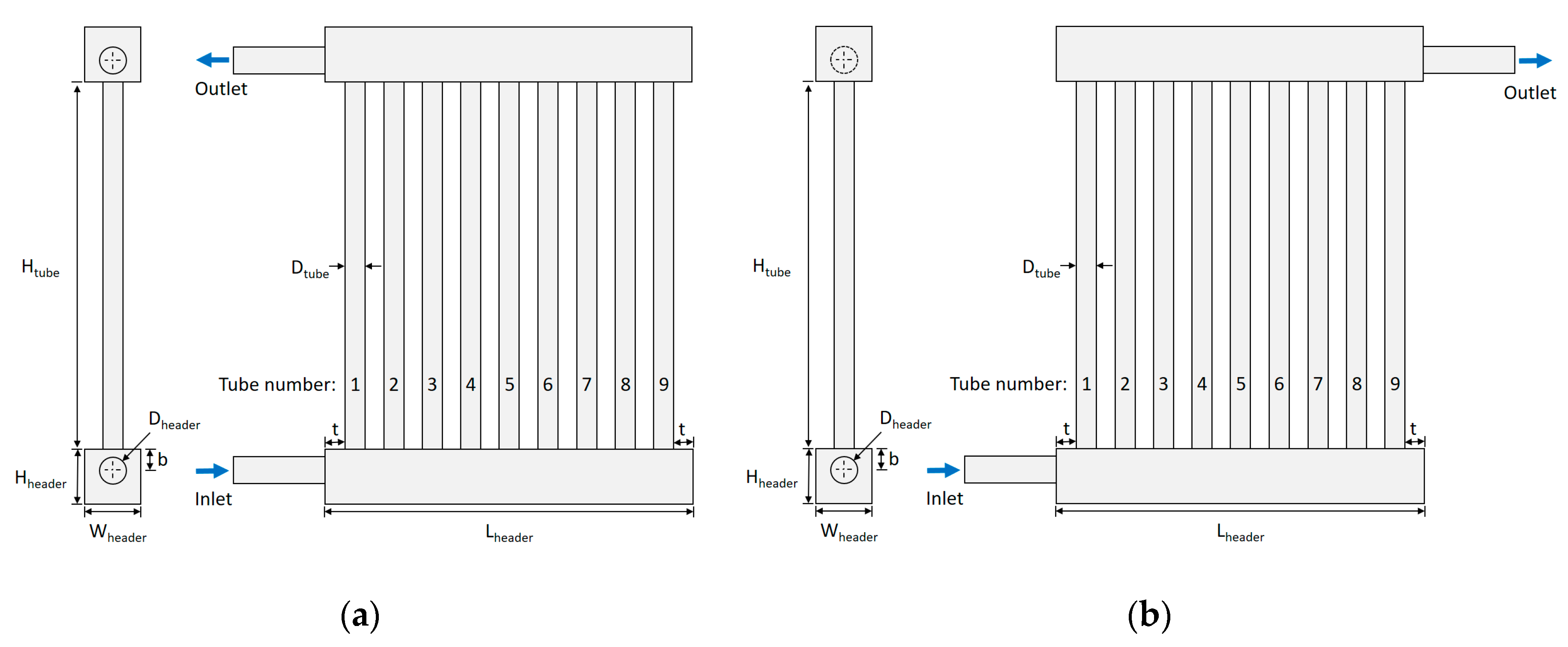
Figure 1. Schematic of conventional parallel-flow heat exchangers: (a) U-type; (b) Z-type.
Energies 13 06330 g001
Figure 2. Three-dimensional (3D) polyhedral mesh using Fluent meshing: (a) full system; (b) combining manifold; (c) dividing manifold.
Energies 13 06330 g002
Figure 3. Comparison of flow non-uniformity index for different numbers of nodes.
Energies 13 06330 g003
Figure 4. Novel design concept in a dividing manifold: (a) Schematic; (b) 3D model.
Energies 13 06330 g004
Figure 5. Flow characteristics of the base model (U- and Z-types): (a) Static pressure distribution; (b) velocity distribution.
Energies 13 06330 g005
Figure 6. Velocity streamlines in the U- and Z-types: (a) dividing and (b) combining manifolds.
Energies 13 06330 g006
Figure 7. Flow distribution comparison between the U- and Z-types.
Energies 13 06330 g007
Figure 8. Pressure and velocity distributions along flow axis of U-type manifold: (a) Static pressure plot; (b) velocity plot.
Energies 13 06330 g008
Figure 9. Pressure and velocity distributions along flow axis of Z-type manifold: (a) Static pressure plot; (b) velocity plot.
Energies 13 06330 g009
Figure 10. Flow uniformity index and non-dimensional total pressure drop for the parameter studies of novel designs: (a) U-type; (b) Z-type.
Energies 13 06330 g010
Figure 11. Correlation among parameters in novel U-type manifold design: (a) Flow uniformity index vs. shape factors and axial installation locations; (b) non-dimensional pressure drop vs. shape factors and axial installation locations.
Energies 13 06330 g011
Figure 12. Correlation among parameters in novel Z-type manifold design: (a) Flow uniformity index vs. shape factors and axial installation locations; (b) non-dimensional pressure drop vs. shape factors and axial installation locations.
Energies 13 06330 g012
Figure 13. Comparison of flow characteristics between the base model and novel designs: (a) U-type; (b) Z-type.
Energies 13 06330 g013
Figure 14. Result comparison between novel designs by parameter changes and the benchmark test model. Flow distribution of each tube in (a) U-type and (b) Z-type.
Energies 13 06330 g014
Figure 15. Sample of velocity contours in the U-type adopting a novel design.
Energies 13 06330 g015
Table 1. Geometric sizes of the benchmark test model (units: mm).
DtubeDheaderHtubeHheaderWheaderLheaderbt
34400999053.5
Table 2. Flow uniformity index comparison between experimental data and computational fluid dynamics (CFD) simulation.
ExperimentCFD% Error
U-type0.0209 [5]0.02070.96
Z-type0.0245 [8]0.02373.27
Table 3. Geometric parameters for novel designs (units: mm).
ParametersValue 1Value 2Value 3Value 4Total Number of Cases
Laxial56.3858.1359.6361.134 × 3 × 3 = 36
Lquad8.0010.0012.00-
Hquad3.004.055.40-
Publisher’s Note: MDPI stays neutral with regard to jurisdictional claims in published maps and institutional affiliations.