Article

Composite Membranes Using Hydrophilized Porous Substrates for Hydrogen Based Energy Conversion

Department of Green Chemical Engineering, College of Engineering, Sangmyung University, Cheonan 31066, Korea
*
Author to whom correspondence should be addressed.
Energies 2020, 13(22), 6101; https://doi.org/10.3390/en13226101
Submission received: 20 October 2020 / Revised: 18 November 2020 / Accepted: 19 November 2020 / Published: 21 November 2020

Abstract

:
Poly(tetrafluoroethylene) (PTFE) porous substrate-reinforced composite membranes for energy conversion technologies are prepared and characterized. In particular, we develop a new hydrophilic treatment method by in-situ biomimetic silicification for PTFE substrates having high porosity (60–80%) since it is difficult to impregnate ionomer into strongly hydrophobic PTFE porous substrates for the preparation of composite membranes. The thinner substrate having ~5 μm treated by the gallic acid/(3-trimethoxysilylpropyl)diethylenetriamine solution with the incubation time of 30 min shows the best hydrophilic treatment result in terms of contact angle. In addition, the composite membranes using the porous substrates show the highest proton conductivity and the lowest water uptake and swelling ratio. Membrane-electrode assemblies (MEAs) using the composite membranes (thinner and lower proton conductivity) and Nafion 212 (thicker and higher proton conductivity), which have similar areal resistance, are compared in I–V polarization curves. The I–V polarization curves of two MEAs in activation and Ohmic region are very identical. However, higher mass transport limitation is observed for Nafion 212 since the composite membrane with less thickness than Nafion 212 would result in higher back diffusion of water and mitigate cathode flooding.

1. Introduction

The unstable crude oil prices and global warming caused by greenhouse gases drive us to use alternative energy sources. Companies and governments have made substantial investments in new and renewable energy over the past few years [1]. Among the new and renewable energy, hydrogen had begun to be translated into the alternative energy source area due to easy deployment into electricity infrastructure, diversified energy sources to produce hydrogen from fossil fuels to biomass, improvement of local air pollution, and recent matured technologies such as fuel cells and electrolyzers [2,3]. Using the electrochemistry-driven energy conversion technologies, hydrogen could be produced from water by using electricity and could be consumed to convert into the water along with generating electricity (H2 + O2 ↔ H2O) [4,5,6].
Fuel cells are the most promising technology utilizing hydrogen. Proton exchange membrane fuel cells (PEMFCs) using hydrogen as fuel show high efficiency during the direct conversion of chemical energy to electric energy. In addition, there is no greenhouse gas emission when hydrogen is produced by water electrolysis using electricity supplied from renewable energy sources such as wind, solar, biomass, etc. [1,7]. Nevertheless, the installation cost is still higher than conventional energy conversion technology such as internal combustion engine and the technical level of durability and reliability must be raised to a higher level to enter the full-fledged fuel cell market [8,9,10]. Membrane-electrodeassembly (MEA) is a key component in PEMFCs, which consists of a piece of proton exchange membrane (PEM) sandwiched between two catalyst layers as an electrode [11]. The recent approach for PEM development has shifted from more proton conductivity to more proton conductance (in other words, from less resistivity to less areal specific resistance) at low relative humidity and higher temperature. Thus, the development of thinner PEMs is crucial to minimize areal specific resistance by the trade-off between less thickness and mechanical/chemical stability. It directly results in a significant decrease in Ohmic losses which is an increase in stack power density and a decrease in material cost [10]. Mechanical reinforcement of thin PEMs (ca. 10–20 μm) is one of the approaches to overcome less mechanical/chemical stability by thinning the thickness. The reinforcement could be achieved by the development of porous substrate-reinforced composite membranes. It could be done only by filling high-conductivity ionomers into porous substrates or by forming a three-layered structure (ionomer/ionomer filled substrate/ionomer) [12,13,14,15,16,17,18,19,20]. Perfluorosuflonic acid (PFSA) ionomers are still the most frequently used material even though less expensive hydrocarbon membranes have been intensively developed [7,21,22,23] Among many reasons for the use of PFSA ionomers, the main one would be the good stability against mechanical and chemical stress occurring during fuel cell or water electrolysis operation. Since the less volume of PFSA is used compared to non-reinforced PFSA membranes, benefits can be obtained in terms of material cost [12,24,25]. To prepare reinforced composite membranes, PFSA ionomer dispersion normally in a mixed solvent of water and alcohols and poly(tetrafluoroethylene) (PTFE) porous substrate is often used due to high proton conductivity of the ionomers and polymeric compatibility with PFSA, respectively [26,27,28]. Nevertheless, the preparation process of porous PTFE-reinforced PFSA composite membranes is very difficult since not all the hydrophilic ionomer dispersions are compatible with hydrophobic PTFE porous substrates. The fabrication of the composite membranes with an incomplete filling of PFSA ionomers into the substrates causes them to lose mechanical strength and chemical stability as well as gas permeability [29]. However, few studies to discuss the effect of materials for hydrophilic treatment of porous substrates for the preparation of porous PTFE-reinforced PFSA composite membranes have been reported.
The hydrophilization of the hydrophobic material surface could be attained by oxygen plasma, UV radiation, grafting, surface oxidation by strong acids, hydrolysis, coating, or lamination. Hydrophilization treatment with plasma or UV radiation is effective because it directly exposes energy to the hydrophobic material surface. However, the hydrophilization using plasma has a limitation in that the process must be performed in a vacuum state, and the one using long-term or strong UV radiation may damage the material surface to irreversibly change the properties of materials. In addition, there is a limit to completely hydrophilize the inner pores of porous substrates. Similarly, lamination is not good for materials with complicated structure. The coating is lower than the plasma and UV radiation in terms of durability, but it is much simpler than the aforementioned methods and inexpensive. Thus, it is frequently used in the industrial hydrophilization process [30]. Initially, the increase in hydrophilicity of PTFE surfaces was obtained by surfactants, but there are too many parameters to be considered for good wettability [31,32]. Recently, biomimetic materials have been deposited on porous hydrophobic microfiltration/ultrafiltration membranes for better water flux from the oil-in-water emulsion and protein wastewater [33]. It is found that the pyrogallol moiety in gallic acid (GA) with amino-terminated substances (ATS) such as siloxane generated a similar mussel-inspired adhesive coating via Michael addition/Schiff base reactions in alkaline conditions [34,35,36]
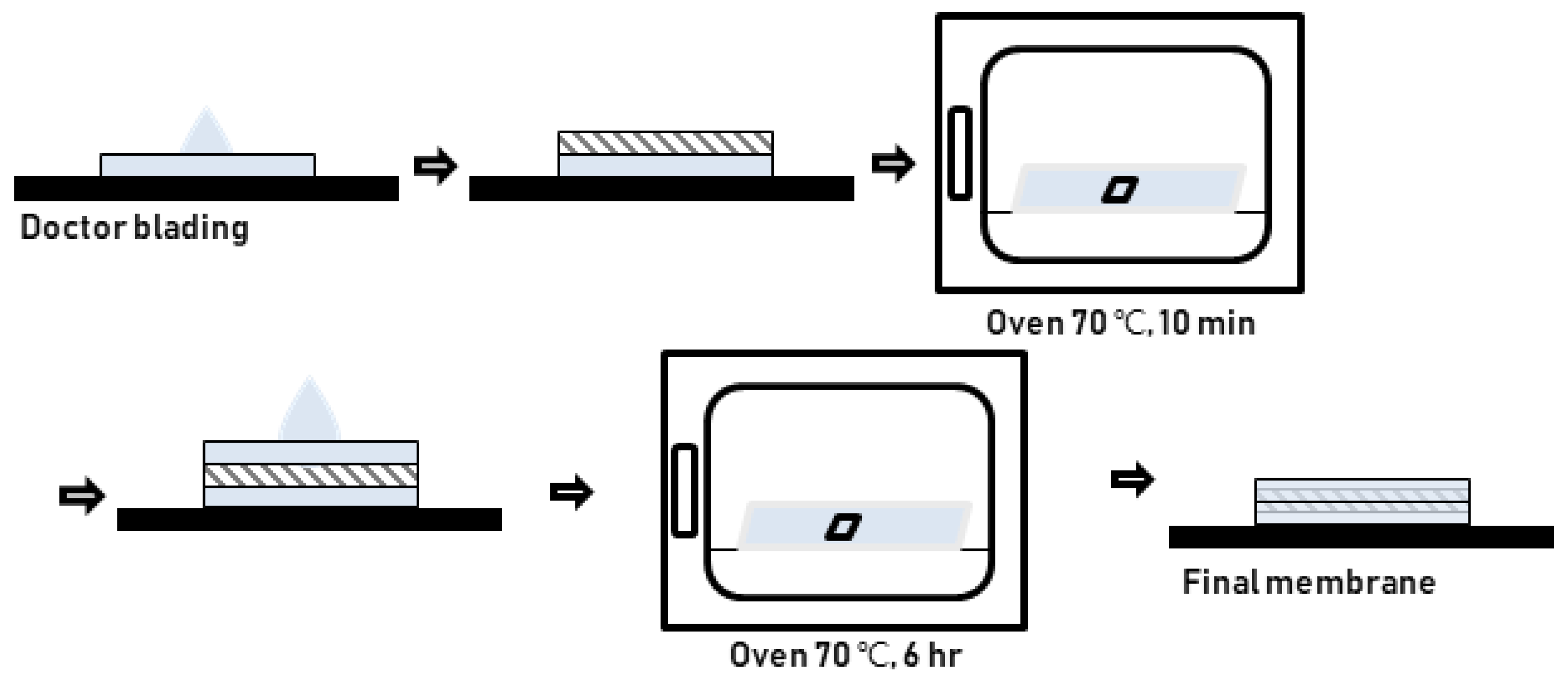
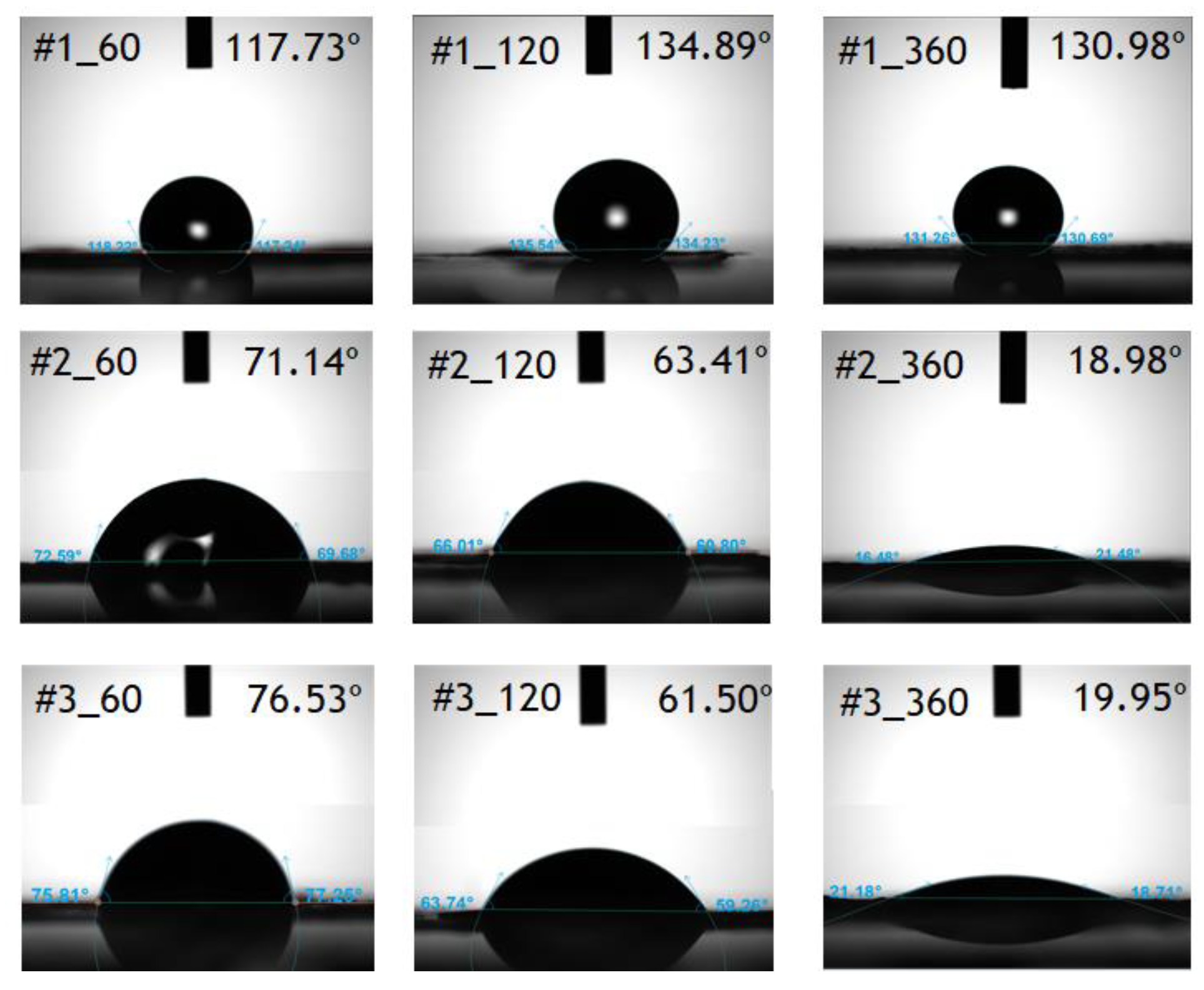
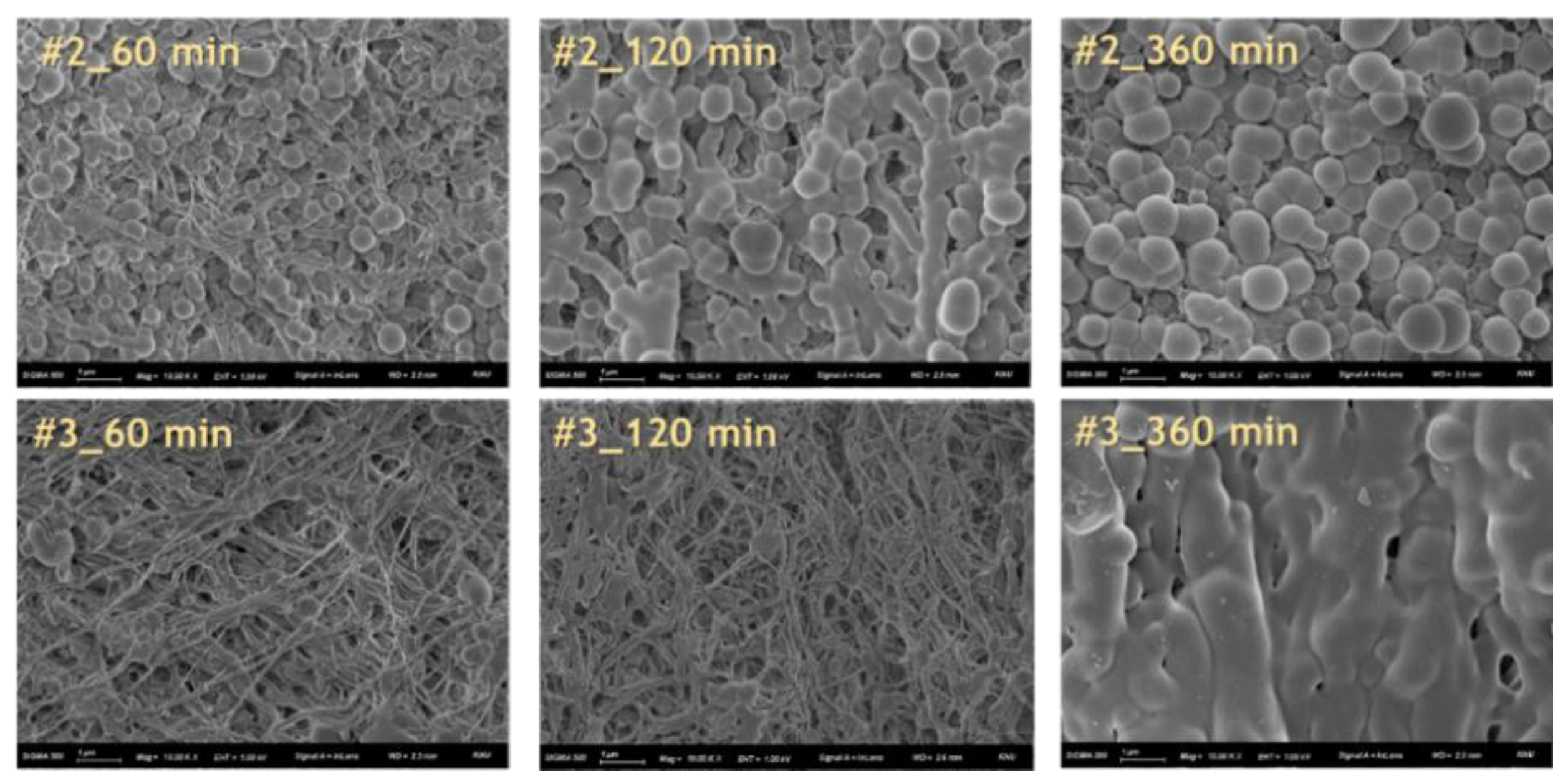
Herein, an approach to increase the wettability of hydrophobic PTFE substrates is investigated by using the nature-born materials, i.e., mussel-inspired silicified polysiloxane adhesive materials, to overcome the aforementioned incompatibility between hydrophobic PTFE substrates and hydrophilic ionomer dispersions. Hydrophilization on porous PTFE substrates (porosity 40‒90%) from the polymerization of GA with respect to the ATS, i.e., 3-aminopropyltriethoxysilane (APTES), N-[3-(trimethoxysilyl)propyl]ethylenediamine (TMPEDA), and (3-trimethoxysilylpropyl)diethylenetriamine (TMPDETA) is carried out, not on microfiltration (MF) or ultrafiltration (UF) which is less porous (porosity <40%) than PTFE. The properties of composite membranes using the porous substrates hydrophilically treated by GA and one of the amino-terminated substances are discussed in terms of water contact angle of hydrophilically treated porous substrates and proton conductivity of composite membranes. Afterward, fuel cell performance of composite membranes is measured and discussed to investigate the effect of the biomimetic coating materials on the properties of porous PTFE-reinforced composite membranes.

2. Materials and Methods

2.1. Materials

Aeos™ ePTFE and PTU0214210 PTFE substrates were purchased from Zeus, the USA, and Sterlitech, USA, respectively. The main physical properties are summarized in Table 1. The 3,4,5-trihydroxybenzoic acid (GA), APTES, TMPEDA, and TMPDETA were obtained from Sigma Aldrich. Their chemical structures are shown in Table 2. For pH 8.5 buffer, trizma® hydrochloride (Tris-HCl) was purchased from Dongin Biotech Co., Ltd., South Korea. All the chemicals were used as received without further purification.

2.2. Hydrophilic Coating of GA/ATS on PTFE Substrates

PTFE substrates were immersed in acetone and ethanol for 6 h, respectively, and then dried in the air prior to hydrophilic treatment. GA of 0.2 g was dissolved in 10 mM Tris-HCl of 100 mL for a GA solution, and three different ATS solutions of 0.13 M using APTES (coded as #1), TMPEDA (coded as #2), and TMPDETA (coded as #3) were prepared in ethanol for ATS solutions. GA/ATS solutions were prepared by mixing 100 mL of the GA solution and 20 mL of the corresponding ATS solution. For the coating of hydrophilic materials, PTFE substrates were immersed in zipper bags filled by the corresponding solutions placed on a plate orbital shaker and were incubated at room temperature for a certain time period under shaking, followed by rinsing with distilled water and drying in the air. The abbreviated incubation conditions are summarized in Table 3.

2.3. Preparation of Porous PTFE-Reinforced Composite Membranes

Reinforced composite membranes were prepared by hydrophilized PTFE substrates and D1021 Nafion™ dispersion (EW 1100, 10 wt.%, Chemours). As shown in Figure 1, the hydrophilically treated porous substrate provides better wettability for the Nafion™ dispersion. However, the untreated pristine one completely repels the dispersion of the substrate surface. The procedure consists of six steps as follows: (1) the PTFE substrates were immersed into the dispersion for 5 min; (2) the membranes were placed on a glass plate doctor-bladed by a film applicator with a thickness of 10 μm; (3) the membranes were dried in a convective oven at 70 °C for 10 min; (4) another 10 μm-layer Nafion was coated on another side of the membranes; (5) the membranes were dried again in a vacuum oven at 70 °C for 6 h; (6) finally the membranes were annealed in a convective oven at 190 °C for 12 min. The scheme of the preparation is illustrated in Figure 2. All the composite membranes were boiled in a 0.5 M H2SO4 solution for 6 h for protonation and boiled in distilled water for 6 h for removal of residual acid prior to use.

2.4. Characterization of Material Structure and GA/ATS Solutions

Measurement of contact angle of PTFE substrates with and without hydrophilic material coating was carried out using a contact angle meter (Attension® Theta Lite, Bioline Scientific, Sweden) as soon as a droplet of the Nafion dispersion falls on substrates. Microcosmic morphology of the substrates and the composite membranes were obtained using a field emission scanning electron microscopy (FE-SEM) system (ZEISS Sigma 500, Germany). Attenuated total reflectance-Fourier transformed infrared spectroscopy (ATR-FTIR) characterization of samples was obtained by a JASCO FT-IR 4700 spectrometer (USA) with an ATR accessory containing a Ge crystal with a wavenumber resolution of 4 cm−1 and range of 600‒4000 cm−1. The microscopic state of GA/ATS solutions was detected by dynamic light scattering (DLS) (ELSZ-1000, Otsuka Electronics Co., Ltd., Japan).

2.5. Characterization of Porous PTFE-Reinforced Composite Membranes

Water uptake of composite membranes was measured by immersing the membranes into distilled water at room temperature for 12 h after the dry membranes (Wdry) were weighed. Afterward, the membranes were taken out, surface water was wiped out, and the wet weight (Wwet) was then measured. Finally, the water uptake of composite membranes was calculated by using the following equation [37]:
Water   uptake ( % ) = W w e t W d r y W d r y × 100 .
The swelling ratio is calculated by the following equation:
Swelling   ratio ( % ) = L w e t L d r y L d r y × 100
where Ldry and Lwet are the dimension (length, width, and thickness) of composite membranes.
The ion exchange capacity (IEC) of composite membranes is firstly soaked in 1.0 M H2SO4 for 24 h to replace functional groups with a proton. The excess acid solution on the surface of the membrane was thoroughly washed off with distilled water, and the membranes were immersed in 1.0 M NaCl (precisely 20 mL) for 24 h. The amount of proton ion-exchanged with Na+ was measured by a titration method with 0.01 N NaOH by an auto-titrator (848 Titrino plus, Metrohm, Switzerland). The IEC was calculated by the following equation:
IEC = n × M × V m
where n is the number of electrons gain or lost, M is the molar concentration of the titration solution (mmol/mL), V is the consumed volume of the titration solution (mL) and m is the weight of the dry membrane [38].
The transport number of composite membranes was measured by using the electromotive force (emf) method which is a method of estimating the transport number of conducting species in ionic and mixed conductors in a two-compartment cell with a composite membrane as a diaphragm in two separate solutions having different concentrations. First of all, composite membranes with a size of 2 × 2 cm2 were immersed in 0.001 M NaCl for 24 h, were taken out, and were installed between two compartment cells which were filled with 0.001 and 0.005 M NaCl on both sides of the cells. Air bubbles on the membrane surfaces were completely removed. Finally, two Luggin capillaries with Ag/AgCl wires filled in a saturated KCl solution were mounted to the nearest locations to the installed membrane. Two wires exposed out of each Luggin capillary reference electrode were then connected to a digital voltage meter (34401A, Agilent, USA) to record voltage between two electrodes. The transport number of composite membranes was calculated by the following equation:
E m = R T F ( 1 2 t + ¯ ) ln C 1 C 2
where, Em is the measured membrane potential, T is the temperature of the solution (K), F is the Faraday constant (96485 C eq−1), R is the ideal gas constant (8.3145 J mol−1 K−1), and C1 is the lower electrolyte concentration, C2 is the higher electrolyte concentration [38].
For the determination of proton conductivity of composite membranes, the electrical impedance of composite membranes was measured. The membranes were cut into a piece with 2 × 2 cm2 and then were impregnated with 1 M H2SO4 for 12 h to replace functional groups into a proton. A piece of a sample was washed with distilled water and was placed in a four-electrode in-plane conductivity cell. The in-plane cell was immersed in distilled water, and the impedance value was measured at a frequency range from 106 to 10−3 Hz using a potentiostat/galvanostat with a frequency response analyzer (SP-150, BioLogic, France). Proton conductivity of composite membranes is calculated by the following equation:
σ   ( S / cm ) = L R · A
where, L is the thickness of a membrane, R is the impedance of a membrane at zero phase angle and A is the cross-sectional area of a membrane.

2.6. Fuel Cell Performance Using Porous PTFE-Reinforced Composite Membranes

The membrane-electrode assemblies (MEAs) were made by a spraying technique using a commercially available Pt-based electrocatalyst (Alfa Aesar HiSPEC™ 4000, USA) with the catalyst loading of 0.4 mg cm−2 and Nafion® 212 (Chemours) or a lab-made composite membrane. MEAs prepared in this study were mounted in a unit cell with an electrode active area of 9 cm2 and were evaluated in a test station (CNL Energy Co. Ltd., Republic of Korea). Hydrogen crossover was measured by using a test station (CNL Energy Co. Ltd., Republic of Korea) at 70 °C, with H2/N2 flows fixed at 0.2/0.2 L min−1 and 2.5 bar absolute pressure in the anode and cathode compartment. The cell operation conditions were in 100% relative humidity for both anode and cathode and the cell temperature of 70 °C. The fuel and oxidant were hydrogen and air to the anode and cathode with a stoichiometry ratio of 1.2 and 2.0, respectively.

3. Results and Discussion

3.1. Characterization of GA/ATS Solutions

Surface coating of adhesive hydrophilic materials is based on the synthesis of polysiloxane from GA/ATS, which is caused by adhesive deposition of the mussel-inspired coating [35]. To confirm in-situ biomimetic silicification, the reactions between GA with the catechol hydroxyl moiety and ATS with the amino moieties have been investigated. Firstly, the visual observation of GA/ATS solutions with incubation time was carried out. Figure 3 shows the co-deposition of GA and ATS. Color and transparency of the GA/#1 change and the co-deposit particles in the GA/#1 solution are not clearly formed. It is, however, observed that the GA/#2 and GA/#3 solutions successfully formed the co-deposition. Initially, both solutions are transparent and yellow. As the incubation time increases, the color of the solutions becomes opaque and dark brown by visual observation. This is also confirmed by the laser transmission of the synthetic solutions in Figure 3. In all cases, laser light penetrates clear solutions immediately after mixing GA and #2 but does not penetrate any more after 120, 30, and 30 min for the GA/#1, GA/#2, and GA/#3, respectively. In addition, the GA/#3 shows more scattered laser light penetration at the beginning compared to the GA/#1 and GA/#2. It infers that the homogeneous reaction is faster than the others. In the case of the GA/#3, after the incubation time of 120 min, laser light penetrates again since the synthetic material begins to grow massively and to sink, finally permitting laser light to transmit slightly again through the supernatant.
The hydrophilic treatment of the porous PTFE-substrates could be attained by the self-coating of the adhesive polysiloxane on the surface of the two kinds of substrates when the substrates are immersed in the GA/ATS/alkaline buffer solutions. The self-coating results in a decrease in the contact angle of the surface of the substrates in a solid-water-air system. Normally, the surface is hydrophobic when the contact angle larger than 90° and hydrophilic when the contact angle is less than 90°. As shown in Figure 4, the treatment of GA and #1 results in no decrease in contact angle as the incubation time increases, which means that the surface of both substrates was not treated to be hydrophilic. It was reported that GA and #1 in alkaline buffer successfully deposited hydrophilic polysiloxane on MF and UF filters [33]. However, no significantly hydrophilic coating was attained for the substrates with higher porosity than MF and UF. In contrast, #2 and #3 with GA in alkaline buffer successfully achieved the hydrophilic coating on the substrates. Thus, the GA/#1 was excluded for further hydrophilic treatment. Figure 5 shows the change in the contact angle of the surface of two substrates treated by GA/#2 and GA/#3 with incubation time. Hydrophilicity in all the cases increased with the incubation time. The minimum incubation time for the increase was 30 min for both GA/ATS solutions. It was observed that there was no change in hydrophilicity prior to 30 min. A decrease rate in the contact angle for the thinner substrate (Zeus) was greater than the thicker substrate (Sterlitech). There is no distinct difference in hydrophilic coating for the thicker substrate with the type of the solutions, but better hydrophilic treatment by the GA/#3 for the thinner substrate is observed than that by the GA/#2. In addition, the contact angle of the GA/#3 treated thinner substrate only becomes less than 90° with an incubation time of 30 min. As a result, the combination of the thinner substrate having ~5 μm and the GA/#3 solution is effective for hydrophilic coating by in-situ biomimetic silicification. In particular, the ATS with the longer amino moieties results in better Michael addition and Schiff base reactions with the catechol hydroxyl moiety of GA. In addition, according to the results of the size distribution of co-deposits formed in the GA/#2 and GA/#3 solutions (see Figure 6 and Table 4), the GA/#3 forms narrower and smaller particles than the GA/#2 as the incubation time increases. Hence, the porous substrate immersed in the GA/#3 results in better hydrophilic treatment. It could be concluded that the hydrophilic treatment of the Zeus porous PTFE substrates in the GA/#3 solution for 30 min incubation time is optimal.
As shown in Figure 7, the microscopic surface morphology of porous substrates shows an obvious coating layer after simple immersion in the GA/#2 and GA/#3 solutions in the corresponding SEM images. However, after the incubation time of 120 min, the coating material covers most of the surface of porous substrates. It could cause improper impregnation of PFSA ionomers into porous substrates due to the blocking of the surface pores of substrates by the covered hydrophilic material. As a result, Zeus porous substrates immersed in the GA/#3 show a significant decrease in contact angle less than 90° at the incubation time of 30 min due to the formation of smaller co-deposits.

3.2. Characterization of GA/ATS-Treated Porous PTFE Substrate Based Composite Membranes

As determined earlier, the GA/#3 and Zeus porous substrates are only used for the preparation of composite membranes. Table 5 summarizes the results of the physical characterization of the composite membranes using GA/#3 treated Zeus porous substrates. All data in Table 5 are the average values of five samples with less than 10% standard deviation. The thickness of the composite membranes increased as the incubation time increased in all composite membranes. When the hydrophilically treated porous substrates were immersed in PFSA dispersion in the first step of the preparation of composite membranes, the porous substrates with higher incubation time absorbed more PFSA dispersion. It results in an increase in thickness for composite membranes with higher incubation time in the GA/#3. Thick composite membranes have thick skin layers on both sides of substrates since the thickness of substrates is similar. Accordingly, the water uptake of the composite membranes also increases as the incubation time increases. The main reason for using composite membranes in fuel cell applications is the suppression of swelling ratio in the area since the electrodes coated on polymeric electrolyte membranes could be cracked due to continuous areal expansion and contraction of membranes by hydration and dehydration during on and off cyclic operation of fuel cells [39]. Due to the skeleton effect of porous substrates, the variation of swelling ratio in the area is lower than that in thickness. Similarly, both swelling ratios also increase with the incubation time.
Table 6 summarizes the results of the characterization of the composite membranes using GA/#3 treated Zeus porous substrates. All data in Table 6 are the average values of five samples with less than 6% standard deviation. As discussed earlier, the higher amount of hydrophilic co-deposits is coated on the substrate as the incubation time increases. Consequently, the inactive volume for proton transport increases, leading to a decrease in the ion-conducting fraction of the composite membranes which was comprised of pore-impregnated PFSA ionomer. Hence, it is observed in Table 6 that the ion conductivity of the composite membranes using the porous substrates with higher incubation time decreases. Similarly, the ion exchange capacity of the composite membranes also decreases with incubation time since the equivalent weight of the sulfonic acid group of PFSA ionomer in dry weight of composite membranes decreases. In addition, the transport number representing the ability of permselectivity of proton for the composite membranes using porous substrates treated by the GA/#3 for the incubation time greater than 120 min decreases substantially. It means that the composite membranes still have pores to allow to penetrate co-ions. It might be due to the coverage of hydrophilic co-deposits on the surface of the substrate or the filling of those into the substrate. The co-deposits could not provide permselectivity and result in a decrease in transport number.
Among the composite membranes, the GA/#3_30-treated composite membrane is chosen to compare with Nafion 212 as reference. As summarized in Table 7, the composite membrane has a very similar areal resistance to Nafion 212 even though the proton conductivity of the composite membrane is less than that of Nafion 212 due to thickness difference. It is presumed that they could lead to very similar fuel cell performance. Figure 8 shows I–V polarization curves of the MEAs using Nafion 212 and the composite membrane. First of all, it was found that the crossover of hydrogen in the MEA using the GA/#3_30-treated composite membrane exhibited approximately 0.5 mA cm−2 which confirms no defect composite membrane. As expected, the I–V polarization curves of two MEAs in activation and Ohmic region are very identical, but higher mass transport limitation is observed for Nafion 212. The main reason to show higher mass transport voltage loss at high current densities is due to water flooding at cathode since a water forming oxygen reduction reaction occurs as well as proton transport causes electro-osmotic drag from the anode to the cathode [40]. Under the same conditions except for the type of electrolyte membranes in the I–V polarization curves, electrolyte membranes could substantially affect the cathode flooding. The composite membrane facilitates back diffusion of water to prevail on electro-osmotic drag leading to the net water transport toward the anode [41]. Diffusion is driven by a gradient in concentration over a moving distance. Hence, the gradient becomes higher if the moving distance, i.e., the thickness of membranes, is shorter, leading to an increase in diffusion flux. In the same way, the composite membrane with less thickness than Nafion 212 would result in higher back diffusion of water and mitigate cathode flooding. Finally, it leads to lessening the mass transport voltage loss.

4. Conclusions

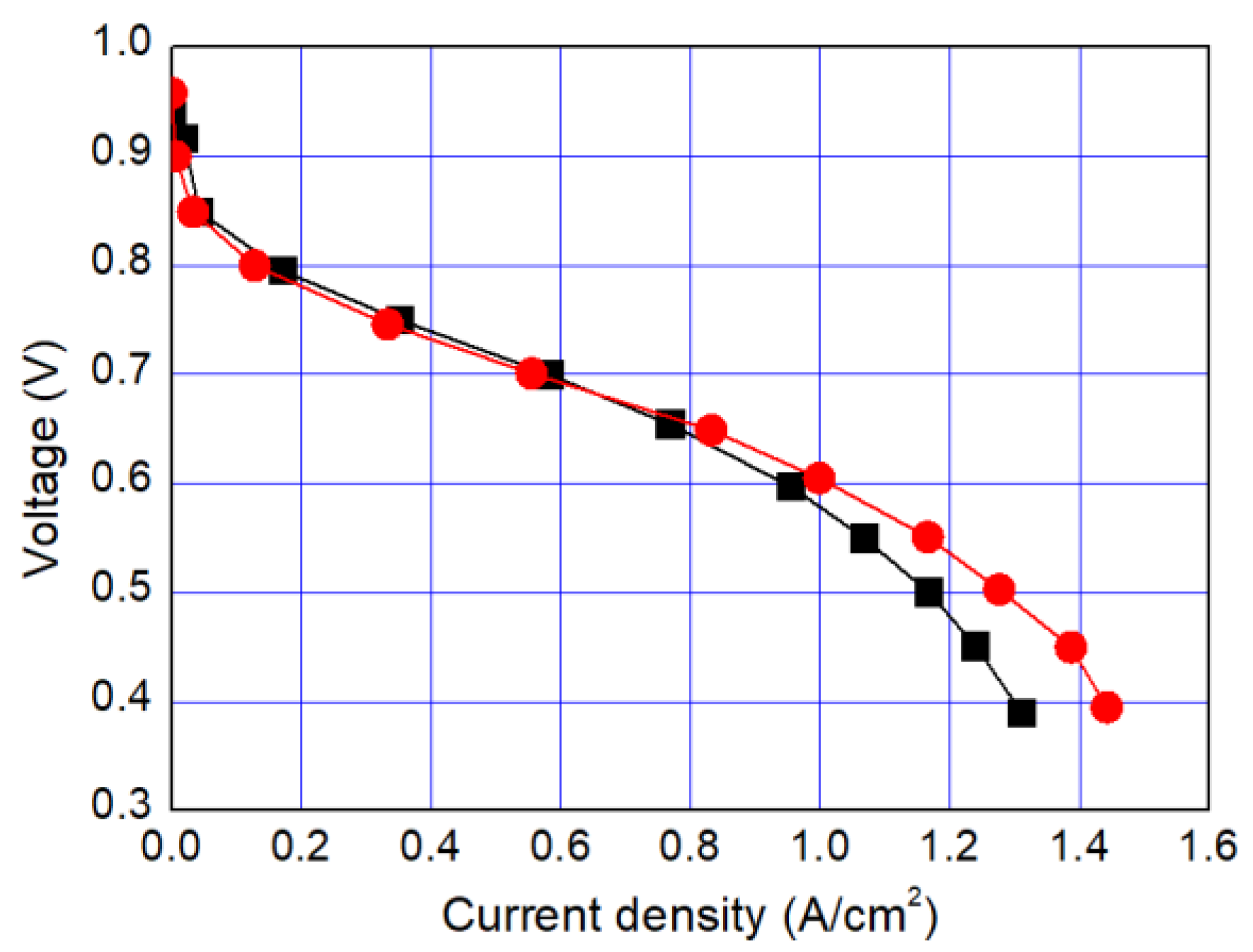
In this study, we have developed a new hydrophilic treatment method for PTFE porous substrates to impregnate PFSA ionomers into strongly hydrophobic porous substrates. Two different PFTE substrates were used: the one has the thickness of ~5 μm and the porosity of ~80% and another has the thickness of ~25 μm and the porosity of ~60%. For hydrophilic treatment, we have used in-situ biomimetic silicification which the pyrogallol moiety in gallic acid (GA) with amino-terminated substances (ATS) such as siloxane generated a similar mussel-inspired adhesive coating via Michael addition/Schiff base reactions in alkaline conditions. We investigated three different ATS materials, i.e., 3-aminopropyltriethoxysilane (APTES), N-[3-(trimethoxysilyl)propyl]ethylenediamine (TMPEDA), and (3-trimethoxysilylpropyl)diethylenetriamine (TMPDETA) with GA. It was found that GA/APTES showed no hydrophilic treatment on both substrates with higher porosity than microfiltration or ultrafiltration membranes. On the other hand, GA/TMPEDA and GA/TMPDETA using ATS with the longer amino moieties showed effective hydrophilic treatment on both substrates. However, GA/TMPDETA has obtained the best contact angle result at less incubation time for the thinner substrates. The thinner substrate having ~5 μm treated by the GA/TMPDETA solution with the incubation time of 30 min shows the best hydrophilic treatment result. In addition, the composite membranes using the porous substrates show the highest proton conductivity and the lowest water uptake and swelling ratio. MEAs using the composite membranes (thinner and lower proton conductivity) and Nafion 212 (thicker and higher proton conductivity), which have similar areal resistance, are compared in I–V polarization curves. The I–V polarization curves of two MEAs in activation and Ohmic region are very identical. However, higher mass transport limitation is observed for Nafion 212 since the composite membrane with less thickness than Nafion 212 would result in higher back diffusion of water and mitigate cathode flooding. It could be concluded that the composite membrane would be advantageous in proton exchange membrane fuel cell application since it has similar areal resistance to Nafion 212 to obtain similar Ohmic loss and less thickness than Nafion 212 to allow higher water flux from cathode to anode to obtain lower mass transport loss in I–V polarization curves.

Author Contributions

Conceptualization, J.-S.P.; methodology, S.L. and J.-S.P.; experimentation, S.L. and J.-S.P.; validation, J.-S.P.; investigation, S.L. and J.-S.P.; resources, J.-S.P.; writing—original draft preparation, S.L. and J.-S.P.; writing—review and editing, J.-S.P.; supervision, J.-S.P.; project administration, J.-S.P.; funding acquisition, J.-S.P. All authors have read and agreed to the published version of the manuscript.

Funding

This research was funded by a 2018 Research Grant from Sangmyung University.

Conflicts of Interest

The authors declare no conflict of interest.

References

  1. Peng, L.; Wei, Z. Catalyst engineering for electrochemical energy conversion from water to water: Water electrolysis and the hydrogen fuel cell. Engineering 2020, 6, 653–679. [Google Scholar] [CrossRef]
  2. The Future of Hydrogen: Seizing Today’s Opportunities. Available online: https://www.iea.org/reports/the-future-of-hydrogen (accessed on 15 October 2020).
  3. Chaube, A.; Chapman, A.; Shigetomi, Y.; Huff, K.; Stubbins, J. The role of hydrogen in achieving long term Japanese energy system goals. Energies 2020, 13, 4539. [Google Scholar] [CrossRef]
  4. Holladay, J.D.; Hu, J.; King, D.L.; Wang, Y. An overview of hydrogen production technologies. Catal. Today 2009, 139, 244–260. [Google Scholar] [CrossRef]
  5. Zhang, W.Q.; Yu, B.; Chen, J.; Xu, J.M. Hydrogen production through solid oxide electrolysis at elevated temperatures. Prog. Chem. 2008, 20, 778–787. [Google Scholar]
  6. Yu, H.; Yi, B. Hydrogen for energy storage and hydrogen production from electrolysis. Strat. Stud. Chin. Acad. Eng. 2018, 20, 58–65. [Google Scholar] [CrossRef]
  7. Park, J.S.; Shin, M.S.; Kim, C.S. Proton exchange membranes for fuel cell operation at low relative humidity and intermediate temperature: An updated review. Curr. Opin. Electrochem. 2017, 5, 43–55. [Google Scholar] [CrossRef]
  8. Uchida, M. PEFC catalyst layers: Effect of support microstructure on both distributions of Pt and ionomer and cell performance and durability. Curr. Opin. Electrochem. 2020, 21, 209–218. [Google Scholar] [CrossRef]
  9. Pollet, B.G.; Kocha, S.S.; Staffell, I. Current status of automotive fuel cells for sustainable transport. Curr. Opin. Electrochem. 2019, 16, 90–95. [Google Scholar] [CrossRef]
  10. Craig, S.G.; Kongkanand, A.; Masten, D.; Gu, W. Materials research and development focus areas for low cost automotive proton-exchange membrane fuel cells. Curr. Opin. Electrochem. 2019, 18, 81–89. [Google Scholar]
  11. Song, C.H.; Park, J.S. Effect of Dispersion Solvents in Catalyst Inks on the Performance and Durability of Catalyst Layers in Proton Exchange Membrane Fuel Cells. Energies 2019, 12, 549. [Google Scholar] [CrossRef] [Green Version]
  12. Liu, F.; Yi, B.; Xing, D.; Yu, J.; Zhang, H. Nafion/PTFE composite membranes for fuel cell applications. J. Membr. Sci. 2003, 212, 213–223. [Google Scholar] [CrossRef]
  13. Tang, H.; Pan, H.; Wang, F.; Shen, P.K.; Jiang, S.P. Highly durable proton exchange membranes for low temperature fuel cells. J. Phys. Chem. 2007, 111, 8684–8690. [Google Scholar] [CrossRef] [PubMed]
  14. Li, M.Q.; Scott, K. A polymer electrolyte membrane for high temperature fuel cells to fit vehicle applications. Electrochim. Acta 2010, 55, 2123–2128. [Google Scholar] [CrossRef]
  15. Zhao, Y.; Yu, H.; Xing, D.; Lu, W.; Shao, Z.; Yi, B. Preparation and characterization of PTFE based composite anion exchange membranes for alkaline fuel cells. J. Membr. Sci. 2012, 421, 311–317. [Google Scholar] [CrossRef]
  16. Wang, L.; Yi, B.L.; Zhang, H.M.; Liu, Y.H.; Xing, D.M.; Shao, Z.G.; Cai, Y.H. Sulfonated polyimide/PTFE reinforced membrane for PEMFCs. J. Power Sources 2007, 167, 47–52. [Google Scholar] [CrossRef]
  17. Kim, K.H.; Ahn, S.Y.; Oh, I.H.; Ha, H.Y.; Hong, S.A.; Kim, M.S.; Lee, Y.K.; Lee, Y.C. Characteristics of the Nafion®-impregnated polycarbonate composite membranes for PEMFCs. Electrochim. Acta 2004, 50, 577–581. [Google Scholar] [CrossRef]
  18. Rodgers, M.P.; Berring, J.; Holdcroft, S.; Shi, Z. The effect of spatial confinement of Nafion in porous membranes on macroscopic properties of the membrane. J. Membr. Sci. 2008, 321, 100–113. [Google Scholar] [CrossRef]
  19. Tezuka, T.; Tadanaga, K.; Matsuda, A.; Hayashi, A.; Tatsumisago, M. Utilization of glass paper as a support of proton inorganicorganic hybrid 3-glycidoxypropyltrimethoxysilane. Electrochem. Commun. 2005, 7, 245–248. [Google Scholar] [CrossRef]
  20. Lee, J.R.; Kim, N.Y.; Lee, M.S.; Lee, S.Y. SiO2-coated polyimide nonwoven/Nafion composite membranes for proton exchange membrane fuel cells. J. Membr. Sci. 2011, 367, 265–272. [Google Scholar] [CrossRef]
  21. Miyahara, T.; Hayano, T.; Matsuno, S.; Watanabe, M.; Miyatake, K. Sulfonated polybenzophenone/poly(arylene ether) block copolymer membranes for fuel cell applications. ACS Appl. Mater. Interfaces 2012, 46, 2881–2884. [Google Scholar] [CrossRef]
  22. Goto, K.; Rozhanskii, I.; Yamakawa, Y.; Otsuki, T.; Naito, Y. Development of aromatic polymer electrolyte membrane with high conductivity and durability for fuel cell. Polym. J. 2009, 41, 95–104. [Google Scholar] [CrossRef] [Green Version]
  23. Gubler, L.; Nauser, T.; Coms, F.D.; Lai, Y.H.; Gittleman, C.S. Prospects for durable hydrocarbon-based fuel cell membranes. J. Electrochem. Soc. 2018, 165, 3100–3103. [Google Scholar] [CrossRef] [Green Version]
  24. Nouel, K.M.; Fedkiw, P.S. Nafion (R)-based composite polymer electrolyte membranes. Electrochim. Acta 1998, 43, 2381–2387. [Google Scholar] [CrossRef]
  25. Yamaguchi, T.; Miyata, F.; Nakao, S. Polymer electrolyte membranes with a pore-filling structure for a direct methanol fuel cell. Adv. Mater. 2003, 15, 1198–1201. [Google Scholar] [CrossRef]
  26. Penner, R.M.; Martin, C.R. Ion transporting composite membranes: I. Nafion-impregnated Gore-Tex. J. Electrochem. Soc. 1985, 132, 514–515. [Google Scholar] [CrossRef]
  27. Satterfield, M.B.; Majsztrik, P.W.; Ota, H.; Benziger, J.B.; Bocarsly, A.B. In Mechanical properties of Nafion and Nafion/titania membranes for PEM fuel cells. In Proceedings of the 2006 AIChE Annual Meeting, San Francisco, CA, USA, 16 November 2006. [Google Scholar]
  28. Shin, S.H.; Nur, P.J.; Kodir, A.; Kwak, D.H.; Lee, H.; Shin, D.; Bae, B. Improving the mechanical durability of short-side-chain perfluorinated polymer electrolyte membranes by annealing and physical reinforcement. ACS Omega 2019, 4, 19153–19163. [Google Scholar] [CrossRef] [Green Version]
  29. Liu, Y.; Naguyen, T.; Kristian, N.; Yu, Y.; Wang, X. Reinforced and self-humidifying composite membrane for fuel cell applications. J. Membr. Sci. 2009, 330, 357–362. [Google Scholar] [CrossRef]
  30. Cho, E.H.; Cheong, S.I.; Rhim, J.W. Study on the fouling reduction of the RO membrane by the coating with an anionic polymer. Membranes 2012, 22, 481–488. [Google Scholar]
  31. Chaudhuri, R.G.; Sunayana, S.; Paria, S. Wettability of a PTFE surface by cationic–non-ionic surfactant mixtures in the presence of electrolytes. Soft Matter 2012, 8, 5429–5433. [Google Scholar] [CrossRef]
  32. Eykens, L.; Sitter, K.D.; Dotremont, C.; Schepper, W.D.; Pinoy, L.; Bruggen, B.V.D. Wetting resistance of commercial membrane distillation membranes in waste streams containing surfactants and oil. Appl. Sci. 2017, 7, 118. [Google Scholar] [CrossRef] [Green Version]
  33. Yang, X.; Sun, H.; Pal, A.; Bai, Y.; Shao, L. Biomimetic silicification on membrane surface for highly efficient treatments of both oil-in-water emulsion and protein wastewater. ACS Appl. Mater. Interfaces 2018, 10, 29982–29991. [Google Scholar] [CrossRef] [PubMed]
  34. Zhan, K.; Kim, C.; Sung, K.; Ejima, H.; Yoshie, N. Tunicate-inspired gallol polymers for underwater adhesive: A comparative study of ctechol and gallol. Biomacromolecules 2017, 18, 2959–2966. [Google Scholar] [CrossRef] [PubMed]
  35. Cheng, X.Q.; Wang, Z.X.; Guo, J.; Ma, J.; Shao, L. Designing multifunctional coatings for cost-effectively sustainable water remediation. ACS Sustain. Chem. Eng. 2018, 6, 1881–1890. [Google Scholar] [CrossRef]
  36. Cheng, X.Q.; Wang, Z.X.; Zhang, Y.; Zhang, Y.; Ma, J.; Shao, L. Bio-inspired loose nanofiltration membranes with optimized separation performance for antibiotics removals. J. Membr. Sci. 2018, 554, 385–394. [Google Scholar] [CrossRef]
  37. Shin, M.S.; Lim, S.; Park, J.H.; Kim, H.J.; Chae, S.; Park, J.S. Thermally crosslinked and quaternized polybenzimidazole ionomer binders for solid alkaline fuel cells. Int. J. Hydrog. Energy 2020, 45, 11773–11783. [Google Scholar] [CrossRef]
  38. Kim, D.H.; Choi, Y.E.; Park, J.S.; Kang, M.S. Capacitive deionization employing pore-filled cation-exchange membranes for energy-efficient removal of multivalent cations. Electrochim. Acta 2019, 295, 164–172. [Google Scholar] [CrossRef]
  39. Seo, D.; Lee, J.; Park, S.; Rhee, J.; Choi, S.W.; Shul, Y.G. Investigation of MEA degradation in PEM fuel cell by on/off cyclic operation under different humid conditions. Int. J. Hydrog. Energy 2011, 36, 1828–1836. [Google Scholar] [CrossRef]
  40. Ji, M.; Wei, Z. A review of water management in polymer electrolyte membrane fuel cells. Energies 2009, 2, 1057–1106. [Google Scholar] [CrossRef] [Green Version]
  41. Nguyen, T.V.; White, R.E. A water and heat management model for proton-exchange-membrane fuel cells. J. Electrochem. Soc. 1993, 140, 2178–2186. [Google Scholar] [CrossRef]
Figure 1. Wettability test of the Nafion™ dispersion on pristine (A) and GA/#3_60-treated PTFE porous substrates (B).
Energies 13 06101 g001
Figure 2. Schematic diagram of the preparation of porous PTFE-reinforced composite membranes.
Energies 13 06101 g002
Figure 3. Visual observation of GA/ATS/alkaline buffer solutions with incubation time (#1): APTES; (#2): TMPEDA; (#3): TMPDETA.
Energies 13 06101 g003
Figure 4. The contact angle of the surface of the porous PTFE substrate (Zeus) treated by GA and APTES (#1) at the first row, GA and TMPEDA (#2) at the second row, and GA and TMPDETA (#3) at the third row with the incubation time of 60, 120, and 360 min from the left-hand side, respectively.
Energies 13 06101 g004
Figure 5. Change of contact angle of the surface of the porous PTFE substrate treated by GA and TMPEDA (#2) at the left-hand side (blue) and GA and TMPDETA (#3) at the right-hand side (red) with incubation time and the type of substrates (Sterlitech in the top row and Zeus in the bottom row).
Energies 13 06101 g005
Figure 6. A dynamic light scattering of the GA/#2 (left) and GA/#3 (right) with incubation time.
Energies 13 06101 g006
Figure 7. SEM images of the surface on the Zeus PTFE substrates after hydrophilic coating (GA/#2 in the top row and GA/#3 in the bottom row).
Energies 13 06101 g007
Figure 8. I–V polarization curves of the membrane-electrode assemblies using Nafion 212 (black) and the composite membrane (red) using the GA/#3_30-treated porous substrate.
Energies 13 06101 g008
Table 1. Specifications of poly(tetrafluoroethylene) (PTFE) substrates used in this study.
SubstratesZeus Aeos™ ePTFESterlitech PTU0459010
thickness (μm)~5~25
porosity (%)~80~60
pore size (μm)0.2‒0.50.45
Table 2. Chemical structures of 3,4,5-trihydroxybenzoic acid (GA), 3-aminopropyltriethoxysilane (APTES), N-[3-(trimethoxysilyl)propyl]ethylenediamine (TMPEDA), and (3-trimethoxysilylpropyl)diethylenetriamine (TMPDETA).
ChemicalsGAATS
APTESTMPEDATMPDETA
chemical structure Energies 13 06101 i001 Energies 13 06101 i002 Energies 13 06101 i003 Energies 13 06101 i004
Table 3. Incubation conditions of PTFE substrates and their abbreviations.
SamplesCoating MaterialsGA/ATS (mL/mL)Incubation Time (min)
#1_60GA/APTES5/160
#1_120GA/APTES5/1120
#1_360GA/APTES5/1360
#2_60GA/TMPEDA5/160
#2_120GA/ TMPEDA5/1120
#2_360GA/ TMPEDA5/1360
#3_60GA/TMPDETA5/160
#3_120GA/TMPDETA5/1120
#3_360GA/TMPDETA5/1360
Table 4. Average sizes of the particles formed in the GA/#2 and GA/#3 with incubation time.
Time (min)Average Particle Sizes (nm)
GA/#2GA/#3
0185205
3011421050
6012641377
9019381781
12030231810
Table 5. Physical properties of composite membranes using Zeus porous substrates with incubation time in the GA/#3 solution.
SamplesThickness (μm)Water Uptake (%)Swelling Ratio (%)
AreaThickness
#3_302711.621.8712.50
#3_402716.524.4013.58
#3_503017.725.4816.67
#3_603322.524.4416.83
#3_1203825.624.3820.69
#3_2403929.326.3222.22
#3_3604035.929.7423.53
Table 6. Electrochemical properties of composite membranes using Zeus porous substrates with incubation time in the GA/#3 solution.
SamplesProton Conductivity (S cm−1)Ion Exchange Capacity (meq g−1)Transport Number (-)Areal Resistance (Ω cm2)
#3_300.0690.8430.990.039
#3_400.0650.8340.990.042
#3_500.0640.8260.990.047
#3_600.0550.8150.990.060
#3_1200.0530.7890.980.072
#3_2400.0500.7620.970.078
#3_3600.0490.7420.850.082
Table 7. Physical properties of Nafion 212 and the composite membrane using the GA/#3_30 and the summary of the I–V polarization curves of the membrane-electrode assemblies using Nafion 212 and the composite membrane.
SamplesThickness (μm)Proton Conductivity (S/cm)Areal Resistance (Ω cm2)Ohmic Resistance from I–V (Ω cm2)High-Frequency Resistance (Ω cm2)
Nafion 212500.120.0420.2120.382
Composite membrane270.0690.0390.2330.409
Publisher’s Note: MDPI stays neutral with regard to jurisdictional claims in published maps and institutional affiliations.

