Abstract
In order to supply the single-phase locomotive load and mitigate the negative sequence current, this paper develops a V/V transformer-based connection and control strategy of three-phase photovoltaic (PV) converters integrated into railway traction power supply systems. In this V/V transformer-based connection, the two-phase traction voltage is converted into the three-phase voltage. This approach can offer a common low voltage AC bus, which is more convenient for more access to three-phase PV converters. Based on this V/V transformer-based connection, an individual phase current control strategy with the hybrid current reference is fully designed. In this control strategy, the current reference, containing two parts, is generated. One is the asymmetrical part for powering the single-phase locomotive load and mitigating the negative sequence current. The other is the symmetrical part for feeding the surplus power back to the utility grid. Then, each phase current replaces the dual-sequence current to be controlled to track the corresponding phase current reference. Consequently, PV converters can flexibly inject the symmetrical and asymmetrical currents without the dual-sequence extraction for a simpler implementation. Finally, the effectiveness of the developed connection and control strategy is validated by the simulation studies.
1. Introduction
In recent decades, renewable resources have attracted more attention and experienced a rapid increase in power generation due to concerns about climate change and environmental pollution [1,2]. Among various types of renewable resources, wind and solar energy continue to dominate, with 176 GW renewable capacity expansion all over the world in 2019, jointly accounting for 90% of the total. Due to the cost reduction and the flexible installation of photovoltaic (PV) panels, PV generation achieves a higher growth than wind power generation. The installed capacity of PV generation increased by 98 GW (+20%) in 2019, and the cumulative installed capacity of PV generation has amounted to 586 GW with a 23% share of global renewable energy generation [3]. However, the drastic increase of PV generation is associated with severe solar curtailment, which is the main obstacle for the future development of PV generation. Thus, the consumption of the electric power produced from PV generation is recently highlighted.
It is noted that the transport sector accounts for 29% of final energy consumption. From an energy and emissions perspective, rail transport is among the most energy-efficient and lowest-emitting transport modes. Furthermore, rail transport is the most electrified transport sector, where three-quarters of the passenger movements and half of the freight trains rely on electricity. It is indicated that the strong growth of railways brings up energy demand such that the total electricity consumption will be nearly 700 TWh by 2050 [4]. The dramatic increase in electricity consumption exacerbates the contradiction of the power supply and demand. Following the Paris Agreement to restrict global temperature rise to 2.0 °C, more renewable energy is expected to be consumed in the form of electricity, which is forecasted to share 84.8% of the total energy consumption by 2050 [5]. It is essential to upgrade the power supply with additional access to more renewable energy. Several examples of PV generation installed in the rail sector are carried out without increasing land use, which effectively relieves the contradiction of the power supply and demand. In 2011, Japan Rail-East operated its first installed 453 kiloWatt peak (kWp) PV generation at Tokyo Station for serving the traction of Tokaido Line trains [6]. Several other examples of similar installations are a 90 kWp rooftop PV generator at the Korail headquarters buildings [7], a 30 kWp PV generator in Aldershot, England [8], and a 2.4 MWp rooftop PV generator at Shaling railway lots, China [9]. In Reference [10], the total potential of PV generation in China’s rail sector is calculated to be 239.6 TWh per year. Meanwhile, the International Energy Agency reports that by 2030, the electricity consumption in China’s rail sector will increase to 191.9 TWh [11]. Together with the 10% utilization rate of the total generation potential, the share of renewable electricity produced by itself is around 12.5%. Consequently, the approach of taking full use of the growing role of PV generation in the rail’s own available space plays an important role in the railway power supply with more renewable energy and fewer carbon emissions.
The most common solution is to connect PV generation to the high voltage 110 kV or 220 kV bus of the railway feeder stations with no modification on railway traction power supply systems (TPSSs) [12,13]. Since the output voltage of PV panels and PV converters are relatively low, a high-ratio transformer is needed for the power delivery. Meanwhile, the locomotive load is connected to the railway traction network, which is powered by a step-down transformer in railway TPSSs. The entire delivery of solar power is complicated by multi-transformers with more power loss. Thus, a direct connection of PV converters to the traction network is preferred. In Reference [14], a single-phase-based connection of PV converters to the TPSSs is designed. Two AC ports of the back-to-back single-phase converter are connected to the secondary-side of two single-phase step-down transformers, respectively. A DC/DC converter is connected to the common DC link of the two DC/AC converters to deliver the maximum power of the PV panels. Due to the absence of a common bus, it is difficult to access more PV converters at the connection point. In Reference [15], a multi-port railway power conditioner with a common DC bus is proposed. Two AC ports of the single-phase cascaded H-bridge converter are directly connected to the railway traction network without transformers. A three-port isolated DC/DC converter is employed in this configuration, whose high-voltage DC ports are connected to the corresponding high-voltage DC links of H-bridge modules, and low-voltage DC ports are connected to a common bus to access more converters. However, this implementation is of high complexity with H-bridges and three-port isolated DC/DC converters. Besides, for guaranteeing the balanced current injection and the constant power delivery, coordinated control of the two single-phase cascaded H-bridge converters are essential, but this would lead to reactive current circulation between two AC ports with more power loss. Thus, the connection of PV converters to TPSSs needs further study.
Since the locomotive is a single-phase load, PV converters are required to inject asymmetrical currents, which consist of both a positive sequence current (PSC) and negative sequence current (NSC). For regulating both PSC and NSC, various controllers are proposed in the stationary reference frame to track the corresponding current reference with zero steady errors, e.g., hysteresis [16], repetitive [17], predictive [18], back-stepping [19], and proportional plus resonant (PR) controllers [20]. Several generation strategies for asymmetrical current provision are presented on the basis of instantaneous power theory for achieving a variety of power characteristics [21,22,23,24]. These current generation strategies all have predefined control targets, such as the rebalance of injected currents [21], the mitigation of DC voltage fluctuations [22], and the achievement of constant active and reactive power [23,24]. For a compromise among the aforementioned targets, a flexible reference generation of PSC and NSC is given in Reference [25], which is implemented with two extra coefficients. The common focus of all the reference generation strategies is on directly regulating PSC and NSC for controlling the power oscillations in the three-phase system, which is considered only from the grid point of view. However, seen from the load point of view, limited work has been done considering single-phase electric trains.
Therefore, this paper develops a V/V transformer-based connection and individual phase current (IPC) control strategy of PV converters integrated into railway TPSSs. In this connection, another V/V transformer is introduced to convert the two-phase traction voltage to the three-phase voltage. This approach can provide an LV AC bus for more access to phase converters. For supplying the locomotive load and mitigating the negative sequence current, an IPC control strategy with a hybrid current reference is developed. In this strategy, the hybrid current reference, containing the symmetrical and asymmetrical parts, is generated in the stationary reference frame. Then, the individual phase current is controlled instead of the positive and negative sequence current to track the corresponding references. Thus, the flexible current injection is achieved for both supplying the locomotive with the asymmetrical currents and feeding back to the utility grid with the symmetrical currents. The rest of this paper is organized as follows. In Section 2, the V/V transformer-based connection of PV converters integrated into railway TPSSs is discussed. In Section 3, an IPC control strategy with a hybrid current reference is fully designed. Then, the simulation results are presented and compared in Section 4. Finally, Section 5 draws the conclusions.
2. Connection Topology
In the railway electrification systems, 50 Hz, 25 kV two-phase AC electrification is dominated due to the simpler implementation and lower power loss. For converting three-phase grid voltage into two-phase traction voltage, several special traction transformers are designed. For single-phase locomotives, the utilization factor is 100% in the V/V transformer, while it is 75.6% in the wye-delta-connected transformer, 81.6% in the Scott transformer, and 84.5% in the Le Blanc transformer [26]. This main advantage of the V/V transformer makes it widely used in the 50 Hz, 25 kV two-phase railway electrification system. Thus, a V/V transformer-based railway TPSS is taken in the following. Figure 1 gives a V/V transformer-based connection of PV converters integrated into the railway TPSSs.
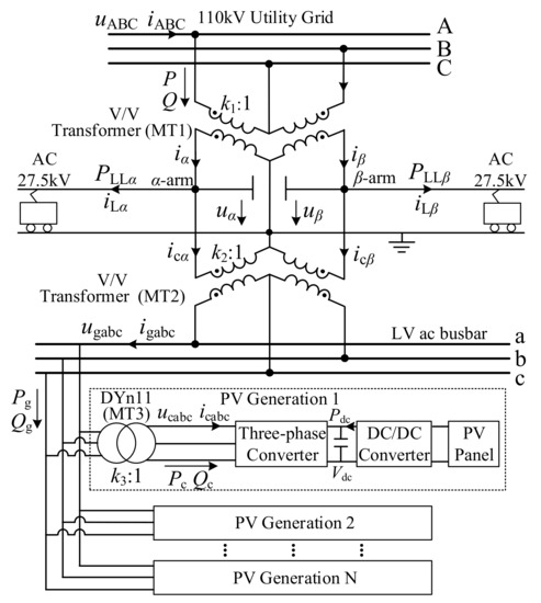
Figure 1.
A V/V transformer-based connection.
As shown in Figure 1, it is used to offer two-phase voltage at 27.5 kV in the traction network with feeder lines, called the α- and β-arm. Another step-down V/V transformer (MT2) is used to convert a two-phase traction voltage of 27.5 kV to a three-phase voltage of 10(6) kV, which is regarded as an LV AC bus. Thereby, it is convenient to access more PV systems typically operating at a low voltage.
In this study, the grid is assumed to be of no zero-sequence voltage and harmonics in a three-phase three-wire system. Accordingly, the line voltage relationship of the utility grid, the traction network, and the LV AC bus can be expressed as,
where k1 and k2 are the ratios of V/V transformer MT1 and MT2, uAB, uBC, uCA are the utility grid line voltages, uα, uβ are the traction voltages, ugab, ugbc, ugca are the LV AC bus line voltages, respectively.
As a result, the line voltage of the LV AC bus is proportional to the utility grid, which is obtained as,
where superscript T refers to the matrix transpose.
It is seen that the LV AC bus can provide three-phase voltage, similar to that of the utility grid, which is convenient for the access of common three-phase PV converters. Then, for stepping down the common bus voltage and suppressing 3rd harmonic currents, an isolated DYn11 transformer (MT3) is introduced in the PV system. Thus, the phase of the common bus line voltage is 30°, lagging that of the converter line voltage. Meanwhile, the amplitude of the bus line voltage is k3 times higher than that of the converter line voltage, where k3 is the ratio of the isolated DYn11 transformer. Based on the equivalent circuit of the DYn11 transformer, the line voltage between phase c and a in MT3′s primary-side winding has the same phase angle as the converter voltage of phase a in the secondary-side winding, but its amplitude is k3 higher than that of the converter phase voltage. Thus, as analyzed, the following voltage and current relationships are obtained as,
where uca, ucb, ucc are the converter phase voltages, ica, icb, icc are the converter currents, and igab, igbc, igca are the phase currents of the primary-side windings, respectively.
Based on (3) and (4), the converter voltage in the terms of the utility grid voltage is obtained as,
As seen, the converter phase voltage is in the same phase as the grid line voltage and proportional to the amplitude of the grid line voltage. Besides, the converter phase voltage contains no zero-sequence voltage, even if there is a zero-sequence grid phase voltage. It is evident that the developed V/V transformer-based connection provides a three-phase LV AC bus for more convenient accesses to the three-phase PV converters. When no locomotive load is on each traction arm, PV converters offer a three-phase symmetrical current injection for the power delivery to the utility grid. It avoids the unbalanced current and the reactive circulation, which are the main advantages of this V/V transformer-based connection.
The current relation of the primary-side and secondary-side of step-down V/V transformer MT1 and MT2 can be expressed as,
where iA, iB, iC are line currents in utility grid, iga, igb, igc are line currents in LV AC bus, iα, iβ are α- and β-arm traction currents, iCα, iCβ are currents injected by the LV AC bus in the α- and β-arm, respectively.
As seen from Figure 1, the traction currents are made up of two parts. One is the locomotive load current produced by electric trains in the traction arm. The other one is the current injected by the PV converter. Thus, the expression of the traction current can be presented as,
where iLα, iLβ are the locomotive load currents in α- and β-arm, respectively.
As a result, together with (6) and (7), the current relation of the utility grid, the locomotive load, and the PV converter is obtained by,
As seen, the current in the utility grid is made up of the locomotive load current and the converter current. If the PV converter is properly controlled with the asymmetrical current provision, the NSC caused by a single-phase locomotive load can be mitigated. As an example, for powering an electric train on an α traction arm, all the solar power is required to be delivered through phases a and c of the LV AC bus, and the current of phase b is controlled to be zero. Since the converter current of each phase has a clear correspondence to the phase current in the LV AC bus, it is recommended to regulate the individual phase current (IPC) of the PV converter instead of the PSC and NSC for the asymmetrical current injection. Under a case that supplies a single-phase locomotive load, the control strategy regulating each phase current has more advantages over the dual-sequence current control, including the obvious correspondence of current and no sequence extraction of voltage and current. As a result, the IPC control strategy is suggested to be employed for PV converters connected to the railway traction network.
3. Control System
3.1. Current Tracking
For the PV converter shown in Figure 1, the front-end DC/DC converter is responsible for delivering the maximum solar power into the common DC link, while the rear-end DC/AC voltage source converter (VSC) is controlled to transfer the DC power into the AC power by maintaining a constant DC link voltage. Since the front-end DC/DC converter is not in the scope of this paper, a stiff power source is connected to the common DC link instead of a DC/DC converter to deliver the solar power. As widely used in VSCs, for maintaining a constant dc-link voltage, a proportional integral (PI)-based DC voltage control loop is applied as
where Vdcref is the reference of the dc-link voltage, kvp and kvi are the proportional and integral parameters, and Pcref is the power reference of the converter, respectively.
Due to the positive direction of current into the converter, the mathematical model of the converter voltage, the modulated voltage, and the converter current is given as,
where vcabc, icabc and ucabc are the modulated phase voltage, the converter phase current, and the converter phase voltage, and L and R are the filter inductance and resistance, respectively.
Then, the modulated voltage vca, vcb and vcc of each phase can be obtained in the stationary abc reference frame as,
where , and are the outputs of the current controllers,
where icaref, icbref and iccref are the current references of phases a, b, and c, and G(s) is the transfer of the adopted current controller, respectively.
It is noted that since all the calculations and implementations are carried out in the stationary reference frame, the current reference in this proposed IPC control strategy must be AC signals. Meanwhile, the proper current provision is needed for supplying the single-phase locomotive load and mitigating the NSC in the utility grid. Consequently, the hybrid current reference containing the asymmetrical and symmetrical parts is essential in the developed IPC control strategy of PV converters integrated in the TPSSs.
3.2. Hybrid Current Reference
In this study, it is assumed that the locomotive load is powered by the α-arm, and no load is on the β-arm in the traction network. According to Figure 1, for supplying this locomotive load, the current is required to be injected through phases a and c of the LV AC bus, and then the phase b current should be controlled to be zero. Since modern electric trains with pulse-width modulation (PWM)-based rectifiers are launched for unity-power-factor operation, PV converters need only inject the active current and power. Then, based on the instantaneous power theory, the active power in the LV AC bus is obtained as,
where ugca is the line voltage between phase c and a, Pg is the active power in the LV AC bus.
Since PV converters are only required to inject the active current, the current of phase c is in the same phase angle as the line voltage ugca between phase c and a, which is calculated as,
where Igm is the line current amplitude of the LV AC bus, Ugm is the line voltage amplitude of the LV AC bus, φ is the phase angle of the line voltage ugca, and ω is the grid angular frequency, respectively.
Submitting (15) into (14), the active power in the LV AC bus is rewritten as,
As seen, the delivered power contains both the average part and the oscillating part at twice the grid frequency. In order to maintain a constant DC link voltage, the average power in (16) must follow the power reference of a DC signal, which is given in (10). Consequently, the injected current amplitude is obtained by,
Together with (15), in the terms of the line voltage of the LV AC bus, the phase current of the LV AC bus is given as,
Then, for providing the injected current in the LV AC bus as required in (18), the output current of the PV converter, i.e., the current reference, is set as,
where Ucm is the amplitude of the converter phase voltage,
As seen, for powering the single-phase locomotive, the asymmetrical current injection of the PV converter is essential. If the solar power is less than the locomotive load, all the solar power is used to supply the locomotive load. Under such a case, the locomotive load is powered not only by the PV converter, but also by the utility grid. When the solar power is larger than the locomotive, the solar power is divided into two parts. One is to supply the single-phase locomotive load and the other one is fed back to the utility grid. If the surplus power is fed back to the utility grid with the asymmetrical current injection, it would introduce current unbalance and power oscillations in the grid.
To address this, a hybrid current reference containing both asymmetrical and symmetrical parts is needed. It can flexibly provide both the asymmetrical current reference for powering the single-phase locomotive and the symmetrical current reference to fed the surplus power back to the grid.
If the locomotive load is larger than the solar power, all the solar power is delivered to the locomotive load with the aforementioned asymmetrical current injection in (20). The other required power is offered by the utility grid and then the asymmetrical grid currents arise in the utility grid. it is noted that this is inevitable due to the power supply of the single-phase locomotive load.
If the solar power is larger than the locomotive load, the partial power supplies the locomotive with the asymmetrical current injection, while the surplus power is fed back to the utility grid with the symmetrical current injection. Thus, the current reference, containing the asymmetrical and symmetrical parts, is expressed as,
where icaref1, icbref1, and iccref1 are the asymmetrical current reference of each phase for powering the single-phase locomotive load, icaref2, icbref2, and iccref2 are the symmetrical current reference of each phase for feeding back to the utility grid, respectively.
As analyzed previously, for powering the single-phase locomotive loads, the asymmetrical current reference is given as,
where PLL is the locomotive load.
It is noted that due to opposite current directions between the feeder line and LV AC bus, a minus sign needs to be inserted to represent the outputted active power of the PV converter.
For feeding the surplus power back to the utility grid, the symmetrical current injection is essential. Under such a case, the current amplitudes of each phase are all equal. Then, for only injecting the active currents, the converter current of each phase is expected to be in the same phase angle as the corresponding phase voltage. Thus, the symmetrical current reference for feeding the surplus power back to the utility grid is given as,
where Icbal is the amplitude of symmetrical current reference.
Together with the positive direction of the current in Figure 1, except for the partial power for the locomotive load, the surplus power for feeding back to the utility grid is calculated as,
where PG is the surplus power feeding back to the utility grid.
Accordingly, the amplitude of the symmetrical current injection is given as,
Consequently, under such a case that the solar power is larger than the locomotive load, the hybrid current reference, containing both the asymmetrical and symmetrical parts, is obtained as,
As seen, the first term is responsible for powering the locomotive with the asymmetrical current, while the second term is for injecting the symmetrical current for feeding the surplus power back to the utility grid. In a per-unit system, the based voltage and current are set as the amplitudes of the rated phase voltage and current of PV converter. The based power is fixed at its rated power. Thus, the based voltage, current, and power is expressed as,
where Ub, Ib and Pb are the based values of voltage, current and power, Icm is the amplitude of the rated current, respectively.
Together with (22) and (26), the hybrid current reference with the flexible injection of both the asymmetrical and symmetrical currents is rewritten in the predefined per-unit system as,
where subscript * refers to the per-unit values, sat( ) and dead( ) are the saturation and dead-zone functions, given as,
It is noted that the voltage fluctuation caused by the locomotive loads may lead to the three-phase voltage unbalance on the converter side. This means that the voltage amplitudes on the converter side may not be equal to each other. Then, as given in (29), the symmetrical current cannot be injected. Thus, to guarantee the symmetrical current injection with the unbalanced voltage, the voltage phase angle is used to replace the instantaneous voltage. The unbalanced current injection caused by the unbalanced voltage is avoided. As a result, (29) can be rewritten as,
where θca, θcb, and θcc, are the voltage phase angle of phase a, b, and c, respectively.
Under another case that the locomotive load is powered by the traction β-arm, similarly to the previous analysis, the hybrid current reference, containing the asymmetrical and symmetrical parts, is given as,
For clear statements, Figure 2 gives a diagram of the hybrid current reference generation. Based on the locomotive power on α- and β-arm, it is easy to switch to the required vector. Then, together with the solar power and the locomotive load, the hybrid current reference, containing the asymmetrical and symmetrical parts, is generated. If all the power is delivered in the form of the asymmetrical current injection, the current amplitude will reach its maximum value. It is twice as much as the rated value, as shown in (32). Consequently, it requires a two-fold larger converter rating for the power delivery under such cases that the PV converters are connected to the TPSS for supplying the single-phase locomotive load.
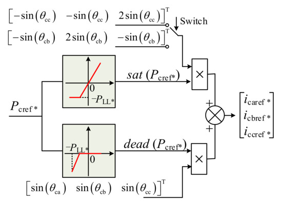
Figure 2.
A diagram of the hybrid current reference generation.
3.3. System Implementation
Figure 3 presents the diagram of the proposed IPC control strategy of PV converters injecting both the symmetrical and asymmetrical currents. In this diagram, the connection point refers to the secondary-side of the DYn11 isolated transformer (MT3). As seen, the proposed IPC control strategy consists of three main parts: (1) the DC link controller guaranteeing that the average DC link voltage tracks its reference with zero steady-state errors; (2) the current reference generation providing the hybrid current reference, containing both the asymmetrical and symmetrical parts, synchronized with the grid voltage; (3) the current controller regulating the feedback current to follow the hybrid current reference. In the part of the current reference generation, the single-phase phase-locked loop is applied to obtain the voltage angle of each phase in the converter side. Since it is not in the scope of this paper, a standard power-based phase-locked loop, as given in Reference [27], is employed to achieve each phase angle of the converter voltage.
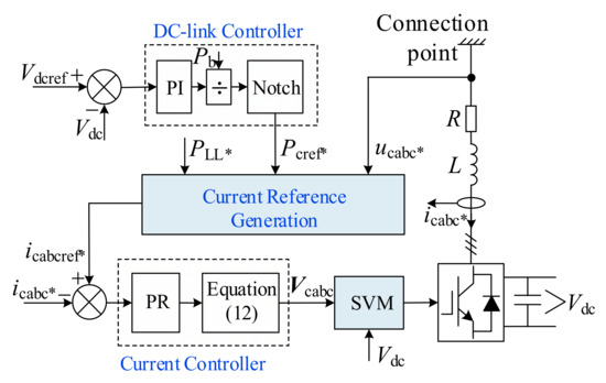
Figure 3.
The diagram of the IPC control strategy.
As analyzed previously, if the solar power is less than the locomotive load, all the solar power is delivered to the locomotive load. Then, the other required power is supplied by the utility grid with the asymmetrical current provision. If the solar power is larger than the locomotive load, the PV converter is controlled to flexibly inject the asymmetrical current for powering the locomotive and the symmetrical current for feeding the surplus power back to the utility grid. As seen, whatever the relationship between the solar power and the locomotive load, the asymmetrical current injection, containing both positive sequence and negative sequence components is always enabled. the asymmetrical current leads to the power pulsations of twice the grid frequency, which would cause the twice-frequency voltage fluctuations in the DC link. As for the DC link PI controller with less control capability of ac signals, its output, i.e., Pcref*, contains a twice-frequency oscillating part. Thus, the twice-frequency ripple, introduced by the DC link controller, arises in the control loop. As indicated in References [28,29], such a ripple would produce the 3rd harmonic component in the current reference.
In order to prevent the generation of the current harmonics, a notch filter tuned at twice the grid frequency is inserted into the control loop for the cancellation of the twice-frequency ripple and is expressed as,
where ξ is a damping ratio and is set as ξ = 0.707.
For the AC current regulation, PR controllers are employed due to the sufficient amplitude gain at operating frequency and the simple implementation among various stationary controllers. For a reduced sensitivity against slight frequency variations around resonant poles, a cutoff frequency ωc = 5–20 rad/s is introduced as a damping factor for both the rapid response and preferable stability. Thus, the complete transfer function of the PR current controller is given as,
where kip and kir are the proportional and resonant parameters, and ωc = 10 rad/s is the cutoff frequency, respectively.
Then, together with the feedforward terms in (12), the modulated converter voltage is obtained,
where Vcabc, Ucabc, and Icabc, are the vectors of the modulated voltage, the converter voltage, and the converter current, Vcabc_PR is the output of the PR controllers, respectively.
Finally, based on the modulated voltage in (35), a space vector modulation is introduced to generate the required switching signals for the PV converter.
As seen, the proposed IPC control strategy regulates each phase current instead of the positive and negative sequence current for the flexible symmetrical and asymmetrical current injection. Meanwhile, the hybrid current reference is generated on the basis of the delivered power and the phase angle in the stationary reference frame. It is noted that the grid condition is assumed to be non-distorted in this paper. To address the harmonic issue in future work, an improved power-based phase-locked loop is needed to extract the phase angle of the fundamental component from the distorted voltage. In order to guarantee the simultaneous regulation of the fundament and harmonic currents with zero steady-state errors, a proportional plus multi-frequency resonant (P-MFR) controller, tuned at the fundamental and harmonic frequencies, is needed. However, as indicated in Reference [30], the introduction of the P-MFR controller leads to the reduced phase margin of the control system and then makes negative impacts on the system stability.
The proposed IPC control strategy need not distinguish the dual-sequence current during the current reference generation and its regulation. Meanwhile, based on the traction power of the α- and β-arm, the proposed IPC control strategy can switch to the proper current reference as given in (31) and (32) for supplying the locomotive load on different traction arms. Thus, compared to the existing solutions, the main advantage of the proposed IPC control strategy is the lack of dual-sequence extraction with a simple implementation.
4. Simulation Results
In order to evaluate the V/V transformer-based connection and IPC control strategy, a simulation model with its main circuit as Figure 1 is developed on Matlab/Simulink (R2020a, MathWorks. Inc, Natick, MA, USA). In this test, an equivalent PV converter of 5.0 MW is used to represent all the converters connected to the common LV AC bus. Since the front-end DC/DC converter is not in the scope, a stiff power source can be applied instead of the front-end converter for delivering the solar power into the common DC link. Most electric trains are equipped with PWM rectifiers and usually operate in the unity-power-factor mode; thus, the locomotive load can be replaced by resistance. All the parameters are listed in Table 1.

Table 1.
Simulation parameters.
In the studies, all the simulation results are given per-unit with a based power of 5.0 MW. The locomotive load of 3.0 MW (0.6 p.u.) is assumed to be on the α traction arm. Due to the single-phase locomotive load, this would lead to voltage unbalance in the high-voltage side and the converter side. Thus, a 5% voltage dip in phases a and c resulting in the unbalanced grid voltage condition is considered in the grid condition. Then, the delivered solar power is initially set at 2.0 MW (0.4 p.u.) and then increased to 5.0 MW (1.0 p.u.) at 0.2 s. For comparing different behaviors with different current references, two operation modes of the PV converter are implemented. In Mode I, the current reference only containing the asymmetrical part, as shown in (19), is always applied in the PV converter regardless of the locomotive load and the solar power. Nevertheless, in Mode II, the hybrid current reference containing both the symmetrical and asymmetrical parts, as shown in (31), is enabled in the control system of the PV converter.
Figure 4 presents the simulation results of Mode I with the asymmetrical current reference. All the simulation results are given in per-unit values.
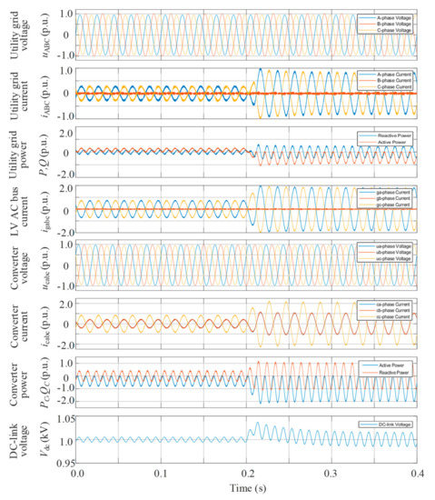
Figure 4.
Simulation results of Mode I with the asymmetrical current reference.
It is noted that in 0–0.2 s, the delivered solar power is initially at 0.4 p.u., which is less than the locomotive load of 0.6 p.u. The PV converter offers the asymmetrical current injection for delivering all the solar power of 0.4 p.u. to the locomotive load, while the remaining required power of 0.2 p.u. is supplied by the utility grid in the form of the asymmetrical current. Under such a case, the injected maximum current of the utility grid reaches around 0.35 p.u. Then, at 0.2 s, the solar power is increased to 1.0 p.u., which is larger than the locomotive load. Under such conditions, all the solar power is still delivered with the asymmetrical current reference given in (19). The converter current is highly sinusoidal with its total harmonic distortion (THD) being 1.8%. However, as with more access to PV converters, the interaction between multi-converters and the traction network may lead to more harmonics in the current provision and may even cause the harmonic instability. This poses new challenges to the stability and power quality in the AC railway [31,32]. For guaranteeing enhanced stability and power quality, several additional methods, including control system optimization, mitigation device installation, and traction network enhancement, can be adopted. Besides, the maximum amplitude of the converter current reaches 2.0 p.u., because all the solar power is delivered through two specific phases with the line voltage instead of three phases with the phase voltage. Focused on the dc-link voltage of the converter, since the asymmetrical current causes the twice-frequency power fluctuations, there would be ±15 V voltage fluctuations in the common dc-link. With Mode I enabled, the surplus power of 0.4 p.u. is fed back to the utility grid with the asymmetrical current injection. Under such conditions, there would inevitably be a current unbalance and twice-frequency power pulsations in the utility grid.
Figure 5 gives the simulation results of Mode II with the hybrid current reference. In this mode, the hybrid current reference is enabled and generated on the basis of the locomotive load and the solar power.
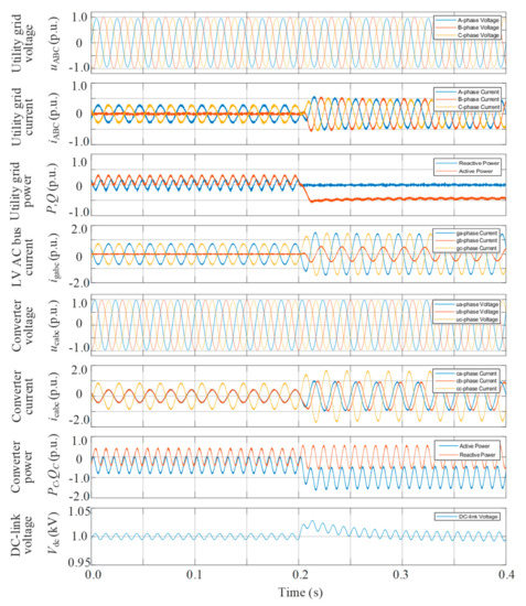
Figure 5.
Simulation results of Mode II with the hybrid current reference.
It is noted that in 0–0.2 s, since the solar power is less than the locomotive load, as analyzed previously, all the solar power is delivered in the form of the asymmetrical current injection for powering the locomotive load. Under such a case, the current reference produced by (31) is the same as that of (19); thus, the simulation results are in the same condition as Figure 4. Except for the partial power offered by the PV converter, the other power of 0.2 p.u. required by the locomotive load is supplied by the utility grid with asymmetrical current provision. Then, at 0.2 s, the solar power is increased to 1.0 p.u., which is 0.4 p.u. larger than the locomotive load. As analyzed previously, the partial solar power of 0.6 p.u. is delivered in the form of the asymmetrical current for supplying the locomotive load, while the surplus solar power of 0.4 p.u. is fed back to the utility grid in the form of the symmetrical current. Since there is the symmetrical current provision for delivering the surplus 0.4 p.u. power, the maximum current amplitude of the PV converter is reduced to 1.6 p.u., which is less than that of Mode I. Due to less asymmetrical current injection with Mode II active, the dc-link voltage fluctuations are suppressed to ±10 V. Focused on the utility grid, the symmetrical current provision with its amplitude being 0.4 p.u. is achieved. However, there are slight power pulsations in the utility grid, which are mainly caused by the unbalanced grid voltage.
For clear comparisons, Table 2 presents the PSC and NSC of the utility grid and the converter with Mode I and II enabled, respectively. When the solar power is less than the locomotive load in 0–0.2 s, all the solar power is delivered through the same asymmetrical current injection in these two cases. Thus, the PSC and NSC in both the utility grid and PV converter are in the same condition. Then, at 0.2 s, the solar power increases to 1.0 p.u., larger than the locomotive load. The solar power can be divided into two parts. One is for powering the locomotive load and the other one is for feeding back to the utility grid. With Mode I employed, the PV converter is controlled to deliver the solar power through the asymmetrical current injection with its PSC and NSC being 1.00 p.u. and 1.00 p.u., respectively. Under such a case, the PSC and NSC in the utility grid are 0.39 p.u. and 0.38 p.u., respectively. It is noted that the NSC in the utility grid is produced by the PV converter in the surplus power delivery. However, with Mode II enabled, the hybrid current reference, containing the symmetrical and asymmetrical parts, is applied on the basis of the locomotive load and solar power. The PV converter is controlled to inject 1.00 p.u. PSC and 0.60 p.u. NSC. The NSC produced by the PV converter can just compensate the NSC caused by the single-phase locomotive load in the traction network. Then, the NSC in the utility grid decreases to 0.0 p.u.
Table 2.
Comparisons of different operation modes.
Figure 6 gives the simulation results of Mode II from the α-arm to the β-arm. In this case, the locomotive load is powered by the α-arm in 0–0.2 s with a 5% voltage dip in phases a and c, while due to the displacement of the train, it is powered by the β-arm in 0.2–0.4 s with a 5% voltage dip in phases b and c. In the simulation, the delivered solar power is assumed to be 5.0 MW (1.0 p.u.). Under such cases, based on the traction power of alpha-arm and beta-arm, the proposed IPC control strategy can switch to the proper current reference as given in (31) and (32). As seen, the proposed IPC control strategy with the hybrid current reference can provide a rapid switching of the current provision based on the locomotive load from the α-arm to the β-arm. Then, the PV converter can still be well controlled to inject the required asymmetrical current for supplying the locomotive, and then the NSC in the utility grid is removed. Thus, the symmetrical current provision is guaranteed in the utility grid with enhanced power quality.
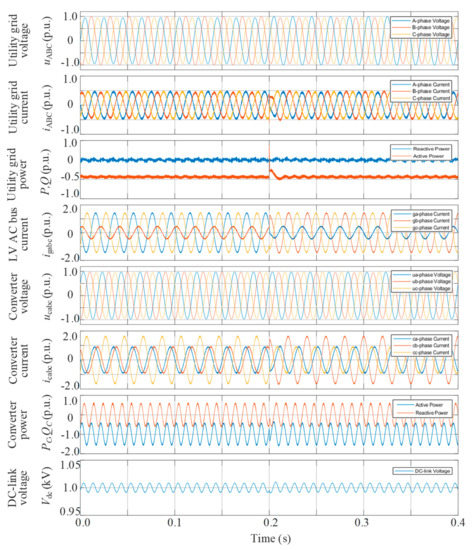
Figure 6.
Simulation results of Mode II from the α-arm to the β-arm.
Therefore, it is evident that the proposed IPC control strategy with the hybrid current reference can not only supply the single-phase locomotive loads with the asymmetrical current injection but also offer the symmetrical current provision for feeding back to the utility grid with enhanced power quality.
5. Conclusions
This paper develops a V/V transformer-based connection and IPC control strategy of PV converters integrated into railway TPSSs. In the V/V transformer-based connection, a common LV AC bus is offered for more access of PV converters with conventional three-phase configuration. Then, to supply the single-phase locomotive load and mitigate the NSC in the utility grid, the IPC control strategy with the hybrid current reference is proposed. In this IPC control strategy, the hybrid current reference of each phase is generated, and then each phase current is controlled well to track its corresponding reference in the stationary reference frame. Then, the asymmetrical and symmetrical currents are flexibly injected without the dual-sequence extraction for a simpler implementation. Thereby, the PV converter operates with the asymmetrical current provision for the supply of the single-phase locomotive load and the symmetrical current provision for mitigating the NSC in the utility grid. Finally, the effectiveness of the V/V transformer-based connection and IPC control strategy is confirmed by the simulation results.
Author Contributions
Conceptualization, P.C. and C.W.; methodology, P.C.; software, P.C. and H.K.; validation, C.W., H.K. and Y.Q.; formal analysis, P.C.; investigation, P.C.; resources, P.C.; data curation, P.C.; writing—original draft preparation, P.C.; writing—review and editing, P.C., C.W. and F.B.; visualization, P.C. and C.W.; supervision, P.C. and F.B.; project administration, P.C.; funding acquisition, P.C. and Y.Q. All authors have read and agreed to the published version of the manuscript.
Funding
This work was funded by the National Natural Science Foundation of China under Grant 51807182 and Zhejiang Provincial Natural Science Foundation of China under Grant No. LQ18E070001.
Conflicts of Interest
The authors declare no conflict of interest.
References
- Marczinkowski, H.M.; Barros, L. Technical Approaches and Institutional Alignment to 100% Renewable Energy System Transition of Madeira Island—Electrification, Smart Energy and the Required Flexible Market Conditions. Energies 2020, 13, 4434. [Google Scholar] [CrossRef]
- Mancini, F.; Nastasi, B. Solar Energy Data Analytics: PV Deployment and Land Use. Energies 2020, 13, 417. [Google Scholar] [CrossRef]
- Renewable Capacity Statistics. 2020. Available online: https://www.irena.org/publications/2020/Mar/Renewable-Capacity-Statistics-2020 (accessed on 8 March 2020).
- Morris, B.; Federica, F.; Hamed, J.K. The Evolution of Railway Power Supply Systems Toward Smart Microgrids. IEEE Electrif. Mag. 2020, 8, 12–23. [Google Scholar] [CrossRef]
- Global Energy Transformation: A Roadmap to 2050 (2019 Edition). Available online: https://www.irena.org/publications/2019/Apr/Global-energy-transformation-A-roadmap-to-2050-2019Edition (accessed on 10 April 2019).
- Hayashiya, H.; Suzuki, T.; Kawahara, K.; Yamanoi, T. Comparative study of investment and efficiency to reduce energy consumption in traction power supply: A present situation of regenerative energy utilization by energy storage system. In Proceedings of the 2014 16th International Power Electronics and Motion Control Conference and Exposition, Antalya, Turkey, 21–24 September 2014; pp. 685–690. [Google Scholar]
- Yoo, J.; Park, C.; Lee, J. A study on design of photovoltaic system using electrical railway stations. In Proceedings of the 19th International Conference of Electrical Machines Systems, Chiba, Japan, 13–16 November 2016. [Google Scholar]
- Riding Sunbeams: Powering Our Railways with Solar PV. Available online: https://www.ridingsunbeams.org/reports (accessed on 6 December 2017).
- Guangzhou Metro’s Yuzhu Depot Completes 5 MW of Largest Metro PV Power Station in China. Available online: https://www.sohu.com/a/283077992_180330 (accessed on 19 December 2018).
- Jia, L.; Ma, J.; Cheng, P.; Liu, Y. A Perspective on solar energy-powered road and rail transportation in China. CSEE J. Power Energy Syst. 2020, 6, 760–771. [Google Scholar]
- The Future of Rail: Opportunities for Energy and the Environment. Available online: https://www.iea.org/reports/the-future-of-rail (accessed on 3 January 2019).
- D’Arco, S.; Piegari, L.; Tricoli, P. Comparative Analysis of Topologies to Integrate Photovoltaic Sources in the Feeder Stations of AC Railways. IEEE Trans. Transp. Electrif. 2018, 4, 951–960. [Google Scholar] [CrossRef]
- Boudoudouh, S.; Maaroufi, M. Renewable Energy Sources Integration and Control in Railway Microgrid. IEEE Trans. Ind. Appl. 2018, 55, 2045–2052. [Google Scholar] [CrossRef]
- Wu, M.; Dai, Z.; Deng, W.; Gao, Y.; Chen, H.; Chen, W. Back-to-back PV generation system for electrified railway and its control strategy. In Proceedings of the 2017 IEEE Transportation Electrification Conference and Expo, Asia-Pacific (ITEC Asia-Pacific), Harbin, China, 7–10 October 2017. [Google Scholar]
- Ma, F.; Wang, X.; Deng, L.; Zhu, Z.; Xu, Q.; Xie, N. Multiport Railway Power Conditioner and Its Management Control Strategy with Renewable Energy Access. IEEE J. Emerg. Sel. Top. Power Electron. 2019, 8, 1405–1418. [Google Scholar] [CrossRef]
- Wang, Y.; Ruan, X.; Leng, Y.; Li, Y. Hysteresis Current Control for Multilevel Converter in Parallel-Form Switch-Linear Hybrid Envelope Tracking Power Supply. IEEE Trans. Power Electron. 2019, 34, 1950–1959. [Google Scholar] [CrossRef]
- Zhang, B.; Zhou, K.; Wang, D. Multirate Repetitive Control for PWM DC/AC Converters. IEEE Trans. Ind. Electron. 2014, 61, 2883–2890. [Google Scholar] [CrossRef]
- Li, J.; Wu, Z.; Gu, W.; Fu, H.; Zhang, X.-P. Aggregator service for PV and battery energy storage systems of residential building. CSEE J. Power Energy Syst. 2015, 1, 3–11. [Google Scholar] [CrossRef]
- Yu, Y.; Mi, Z.; Guo, X.; Niu, X.; Zheng, X.; Sun, C. Control design and implementation of a spiral spring energy storage system connected to a grid via PMSG. CSEE J. Power Energy Syst. 2018, 4, 339–351. [Google Scholar] [CrossRef]
- Fantino, R.A.; Busada, C.A.; Solsona, J.A. Optimum PR Control Applied to LCL Filters with Low Resonance Frequency. IEEE Trans. Power Electron. 2018, 33, 793–801. [Google Scholar] [CrossRef]
- Ma, K.; Chen, W.; Liserre, M.; Blaabjerg, F. Power Controllability of a Three-Phase Converter with an Unbalanced AC Source. IEEE Trans. Power Electron. 2014, 30, 1591–1604. [Google Scholar] [CrossRef]
- Zarei, S.F.; Mokhtari, H.; Ghasemi, M.A.; Peyghami, S.; Davari, P.; Blaabjerg, F. Control of Grid-Following Inverters Under Unbalanced Grid Conditions. IEEE Trans. Energy Convers. 2020, 35, 184–192. [Google Scholar] [CrossRef]
- Cheng, P.; Nian, H. Direct power control of voltage source inverter in a virtual synchronous reference frame during frequency variation and network unbalance. IET Power Electron. 2016, 9, 502–511. [Google Scholar] [CrossRef]
- Jia, J.; Yang, G.; Nielsen, A.H. A Review on Grid-Connected Converter Control for Short-Circuit Power Provision Under Grid Unbalanced Faults. IEEE Trans. Power Deliv. 2018, 33, 649–661. [Google Scholar] [CrossRef]
- Camacho, A.; Castilla, M.; Miret, J.; Borrell, A.; De Vicuna, L.G. Active and Reactive Power Strategies with Peak Current Limitation for Distributed Generation Inverters During Unbalanced Grid Faults. IEEE Trans. Ind. Electron. 2015, 62, 1515–1525. [Google Scholar] [CrossRef]
- Zhang, Z.; Wu, B.; Kang, J.; Luo, L. A Multi-Purpose Balanced Transformer for Railway Traction Applications. IEEE Trans. Power Deliv. 2009, 24, 711–718. [Google Scholar] [CrossRef]
- Golestan, S.; Guerrero, J.M.; Vasquez, J.C. Single-Phase PLLs: A Review of Recent Advances. IEEE Trans. Power Electron. 2017, 32, 9013–9030. [Google Scholar] [CrossRef]
- Karimi-Ghartemani, M.; Khajehoddin, S.A.; Jain, P.; Bakhshai, A. A Systematic Approach to DC-Bus Control Design in Single-Phase Grid-Connected Renewable Converters. IEEE Trans. Power Electron. 2013, 28, 3158–3166. [Google Scholar] [CrossRef]
- Merai, M.; Naouar, M.W.; Slama-Belkhodja, I.; Monmasson, E. An Adaptive PI Controller Design for DC-Link Voltage Control of Single-Phase Grid-Connected Converters. IEEE Trans. Ind. Electron. 2019, 66, 6241–6249. [Google Scholar] [CrossRef]
- Nian, H.; Song, Y. Optimised parameter design of proportional integral and resonant current regulator for doubly fed induction generator during grid voltage distortion. IET Renew. Power Gener. 2014, 8, 299–313. [Google Scholar] [CrossRef]
- Tao, H.; Hu, H.; Wang, X.; Blaabjerg, F.; He, Z. Impedance-Based Harmonic Instability Assessment in a Multiple Electric Trains and Traction Network Interaction System. IEEE Trans. Ind. Appl. 2018, 54, 5083–5096. [Google Scholar] [CrossRef]
- Hu, H.; Zhou, Y.; Li, X.; Lei, K. Low-Frequency Oscillation in Electric Railway Depot: A Comprehensive Review. IEEE Trans. Power Electron. 2020, 36, 295–314. [Google Scholar] [CrossRef]


Publisher’s Note: MDPI stays neutral with regard to jurisdictional claims in published maps and institutional affiliations. |
© 2020 by the authors. Licensee MDPI, Basel, Switzerland. This article is an open access article distributed under the terms and conditions of the Creative Commons Attribution (CC BY) license (http://creativecommons.org/licenses/by/4.0/).