Article

Design Optimization of a Reluctance Lead Screw for Wave Energy Conversion

1
Department of Logistics Engineering, Shanghai Maritime University, Shanghai 201306, China
2
Department of Energy Technology, Aalborg University, DK-9220 Aalborg, Denmark
*
Author to whom correspondence should be addressed.
Energies 2020, 13(20), 5388; https://doi.org/10.3390/en13205388
Submission received: 12 August 2020 / Revised: 6 October 2020 / Accepted: 14 October 2020 / Published: 15 October 2020
(This article belongs to the Section A3: Wind, Wave and Tidal Energy)

Abstract

:
A reluctance lead screw (RLS) is proposed in this paper which consists of a rotor and a translator, forming a magnetic device that is able to transfer low-speed linear motion into high-speed rotational motion. Permanent magnets (PMs) are only installed in the rotor, making it more suitable for long-stroke applications. The design aspects are assessed by finite element analysis (FEA) and the performance is evaluated. In addition, the thrust force per magnet volume is presented for evaluating the utilization rate of the PMs. The simulation results show that RLS has an advantage in terms of the PM utilization rate. A new method for realizing spiral magnets has also been developed which can not only reduce the manufacturing difficulties, but also ease the installation work. Finally, based on the simulations and analyses, two RLS prototypes designed for wave energy converters (WECs) are presented to show the potential applications of this novel topology.

1. Introduction

The ongoing debate about environmental problems and the decrease in fossil fuels have made it necessary for more clean energies to be developed. Although wave energy technologies are far from mature, it is believed that wave energy is able to become a major contributor of energy in the future because of its predictability and availability [1,2]. The key of extracting wave energy is the transmission mechanism; up to now, several transmission structures have been in practical use.
First comes the mechanical gears—they are commonly used in wave energy converters (WECs) [3,4]. Among the many applications of traditional mechanical gears, the demand for linear drive and high force density is essential. Due to the constant mechanical contacts and friction between parts, those mechanical gears are subject to wear and tear, noise, and frequent maintenance. When working in overload situations, they are likely to break down.
The hydraulic power takeoff (PTO) system is a good substitute for mechanical gears and has been utilized in some WECs, such as the Sharp Eagle Xian Dao 1 and Pelamis. Although hydraulic-based WECs enjoy benefits from high pressure levels of up to 35 MN/m2, the transmission efficiency is limited to about 60% [5]. In addition, the hydraulic components require constant maintenance, which is unacceptable for most deep sea applications.
One promising alternative to the above-mentioned devices is the linear permanent magnet (PM) generator, as shown in [6,7,8,9,10]. One representative is the Archimedes Wave Swing (AWS) system, which is a completely submerged device that captures the linear motion with a cylindrical air-filled chamber. A linear PM generator is finally driven by the linear motion. Linear PM generators still need improvements because of their lower force density compared with that of hydraulic actuators.
The magnetic lead screw (MLS) can also realize indirect force transmission [11,12]. The MLS, as depicted in Figure 1, is composed of a magnetic nut (rotor) and a magnetic screw (translator); it can not only transfer linear motion into rotary motion, but also has no direct mechanical contact between the force-transferring parts. Hence, the MLS has an inherent self-protection ability. When the axial force exerted on the translator is too large, the moving parts will slide over some magnet poles and be recoupled at the next magnet poles. Compared with a mechanical coupled device such as the mechanical gear box system, the friction in the magnetic coupled device is much reduced, and this brings MLS another advantage of low maintenance. Thus, the MLS is commonly considered a promising device for WEC applications.
Due to the great changes in wave height, the traditional MLS utilized in WECs is always designed with long strokes, which means that a great number of magnets are required for building its rotor and especially the several-meter-long translator. Actually, the effective working length is equal to the axial length of the rotor magnets, so most magnets on the translator are in a non-working state for most of the time, which is a waste of those expensive materials. To make matters worse, ideal helical magnets are difficult to fabricate and install, and the total cost including materials and labor is unacceptable in mass production. For example, in the prototype MLS designed for Wavestar, up to 4000 pieces of PM blocks are installed to approximate the ideal helical magnet lines [13,14].
Attempting to replace PMs, an electromagnetic lead screw (EMLS) is proposed in [15,16]. The EMLS offers a much simpler, robust structure compared with that of MLS. Magnetic fields are generated from the coils wrapped around the mover threads and can be regulated by varying the currents in the coils. The magnetic field produced by the coil current is generally weaker than the field generated by PMs. A high-temperature superconductor electromagnetic screw is presented in [17], which is developed for an artificial heart. With the help of the superconductor, the force density can be improved effectively but is still lower than that of the MLS.
In this paper, a novel RLS topology for WEC is proposed which utilizes magnets only in one of its moving parts. As a supplement to the traditional MLS, the proposed RLS has advantages in its manufacture costs and PM consumptions. In addition, the magnets are discretized to simplify the fabrication process. Finally, an optimized prototype is designed and the applications in WECs are presented. In this paper, Section 2 includes the working principle and structure of the proposed RLS. Section 3 deals with the design optimizations of the RLS. Section 4 presents the RLS prototype design and potential applications in WECs. The final section is the conclusion.

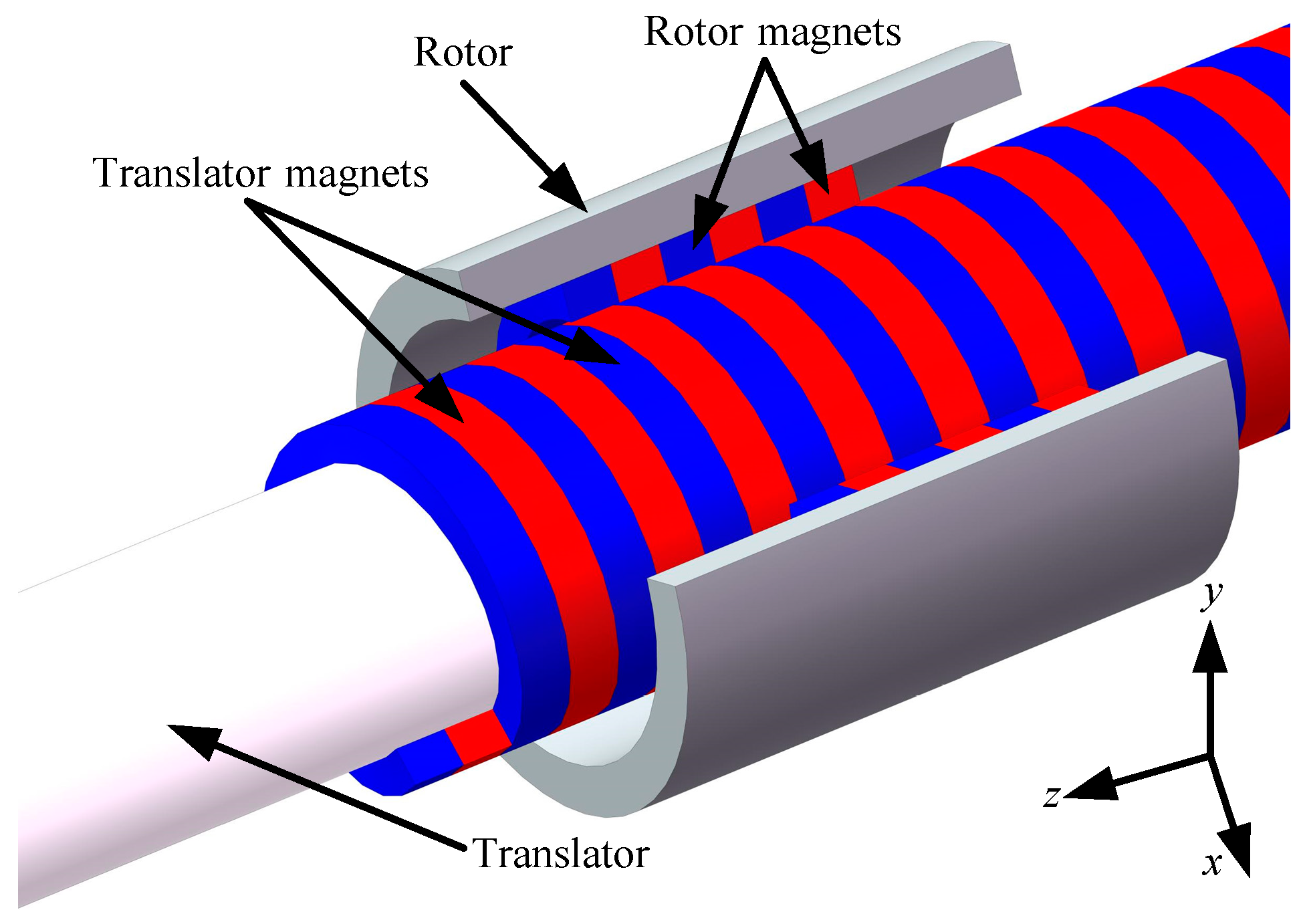
2. Fundamentals and Topology of the RLS

The RLS, as depicted in Figure 2, is a kind of linear actuator which is based on the same principle as the mechanical lead screw and MLS. Hence, RLS is composed of a rotating rotor and a linear translator. The rotor is a hollow cylinder with helically shaped magnets installed inside, and the translator is a lead screw with helical threads installed or manufactured around its cylindrical surface. Different from the traditional MLS, which has a tremendous amount of magnets on both the rotor and the translator, the RLS has no magnets on the translator, which not only saves PM consumption but also simplifies the installation process. The rotor and the translator are installed in the same axis with an air gap between them. The two parts of RLS are coupled by the rotor spiral magnetic field; as a result, when the rotor rotates one revolution, the translator will move linearly by a distance of four pole pitches, realizing the conversion between linear motion and rotary motion.
The rotor and translator are coupled by reluctance, forming an indirect coupling structure in WECs, which brings many advantages compared with conventional methods. For example, RLS has a self-protection ability; when the axial force exerted on the translator is too large, it will slide over some magnet poles and be recoupled with the rotor at the next magnet poles so that the RLS is still able to work. In addition, compared with the mechanical coupled device such as the mechanical gear box system, the friction in RLS is much reduced, and this brings RLS another advantage of low maintenance.
Figure 3 shows the two dimensional symmetric view of the RLS. The shape of the PMs on the rotor is a double helix, so the magnetic field exerted on the translator threads is N-S alternating. The magnetic flux goes from the magnet north pole to the translator thread, and the next thread channels the flux back to the magnet south pole, forming a closed loop. When the translator moves linearly along the z-axis back and forth, the rotor will rotate around the z-axis without linear movement. For example, when the translator moves linearly by the length of four pole pitches, the rotor will rotate by 2π rad, so the gear ratio is defined as follows:
G = π 2 τ p = ω υ ,
where τp is the pole pitch (m), ω is the rotor angular velocity (rad/s), and υ is the translator linear speed (m/s).
If the pole pitch is selected to be 10 mm, then the gear ratio would be 157.08. In this case, the RLS is able to convert the linear speed of 1 m/s into the rotational speed of 1500 r/min, realizing the conversion from low linear speed into high rotational speed. The key advantages of utilizing rotary generators are that they are commercially available for different power ratings with no necessity of designing a new generator, and the power density of rotary generators is usually higher than that of linear generators.
In stable state, the rotor and translator are in the aligned position, so the thrust force is zero, as shown in Figure 4a. In Figure 4b, the magnetic field is not symmetrical because the rotor and translator are axially displaced by 3/5 pole pitch. In this position, both the translator and the rotor generate force. As for the proposed RLS, the maximum thrust force will be reached when the axial displacement between the rotor and translator is 69% of two pole pitches. The effects of the structural parameters and magnet parameters on the RLS performance will be analyzed in the following section.

3. Design Optimization

This section deals with the analysis of the design aspects, including the structure design and magnet design, while affect the thrust force of the RLS. Finite element analyses (FEA) are utilized for evaluating the parameters’ influences [18,19,20]. Due to the fact that electromagnetic finite element analyzing software has been widely used, a simulation model is constructed in such an FEA software to ensure the accuracy of the results. Figures 6–13 are plotted with the simulation results and necessary calculation results.
First of all, a set of basic parameters used for the initial analysis are given in Table 1 and shown in Figure 5. These parameters will be used in the simulations and remain unchanged unless otherwise specified.
Figure 6 shows the force characteristics of the RLS. The rotor is fixed with no movement and the translator moves axially by two pole pitches. From Figure 6, it can be seen that the maximum thrust force of the RLS is reached when the axial displacement between the rotor and translator is about 31% of two pole pitches (λ/2), and the minimum thrust force is reached when the displacement is about 69% of two pole pitches.

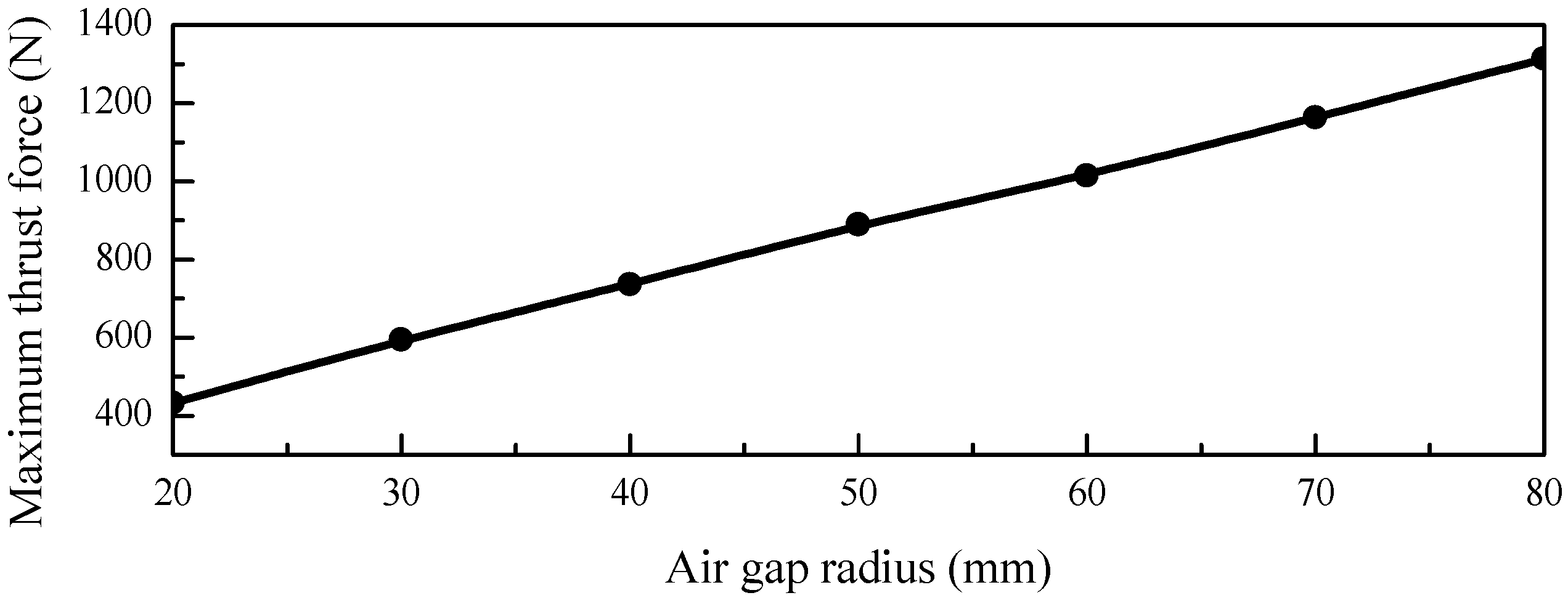
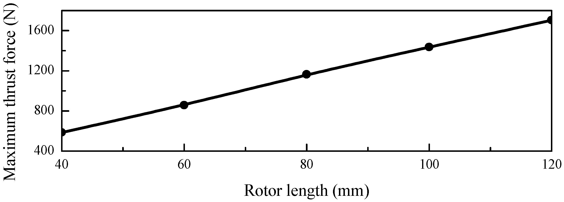
3.1. Ferromagnetic Structure Aspects
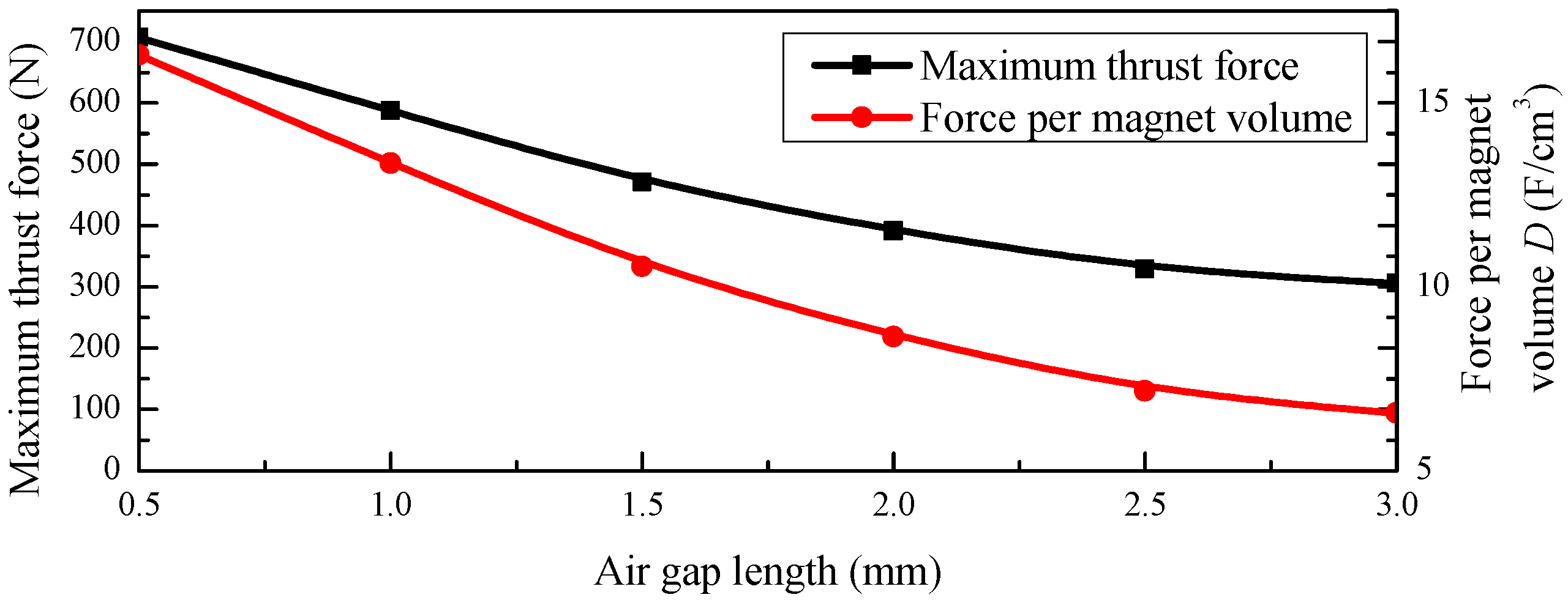
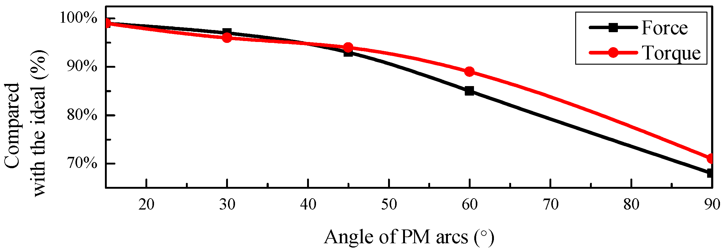
In this section, the ferromagnetic structural parameters are discussed and analyzed, including the rotor materials, air gap length, air gap radius, and thread thickness.
Various methods have been proposed for evaluating the performance of the MLS and linear motor; one of the most commonly used is the force per active volume. As analyzed in [21,22], this method is not suitable for different structures. For the RLS, it is reasonable to evaluate the PM utilization rate directly based on the magnet volume because the PM is the key. The thrust force per PM volume defined in this paper is named FpPM, and it can be calculated by the following equations:
F p P M = F / V p m ,
V p m = n τ p π h m ( 2 R r t i h m ) ,
where F is the maximum thrust force, which is exported from the simulation results; Vpm is the total PM volume, which can be calculated with the simulation parameters; n is the total number of helical magnet turns.
Figure 7 shows the variations in the maximum thrust force with different air gap radii Ra (Ra = Rrtihm). The air gap radius increases from 20 to 80 mm. It can be seen from the results that the maximum thrust force grows linearly when the air gap radius increases. The reason for this is that when the air gap radius increases, the magnet surface areas increase; at the same time, the magnetic flux density remains unchanged, so the force increases with the magnet surface areas. In [23], the MLS maximum thrust force is about 2.5 kN, and the PM volume is 211.0 cm3; the thrust force per PM volume is 11.8 N/cm3. In RLS, the maximum thrust force is about 585 N, the PM volume is 44 cm3, and FpPM is 13.3 N/cm3. Benefitting from the novel structure, the value of FpPM is higher in the RLS compared with in the MLS. In other words, the RLS is able to generate more force than the MLS with the same magnet volume, and it can be concluded that RLS gives better utilization of magnets.
The impacts of the air gap length on the thrust force are depicted in Figure 8. It can be seen that the maximum thrust force drops when the air gap length increases, which is because the air has a poor permeability. Commonly, a smaller air gap length is preferred in order to utilize the PM materials to the utmost, but this can sometimes introduce unexpected operation problems; for example, the magnets and translator threads could touch each other when eccentricity occurs. Based on the simulation results and previous laboratory experience in [24], an air gap of 1 mm is considered practical and reasonable.
The rotor nut is not only a supporting structure for bearing magnets, but also a medium for conducting magnetic fields. Figure 9 presents the comparisons of the maximum thrust force among several commonly used materials. Copper, alumina, and aluminum are non-ferromagnetic materials, so their permeability is not as good as that of iron. If these materials are selected for supporting the magnets, the force performance would be worse than that of the iron rotor. In addition, when the rotor nut material remains unchanged but the nut thickness is set to 0.5, 5, or 10 mm, three simulations show no difference in thrust force.
Threads are the helical structure installed or fabricated on the cylindrical surface of the translator. The thread pole pitch is the same as the rotor PM pole pitch to ensure that the rotor and the translator are stably coupled. Figure 10 illustrates the impacts of the thread thickness on the thrust force. An increase in the thread thickness leads to an increase in the maximum thrust force to some extent. When the thread thickness is set above 5 mm, both the thrust force and the FpPM can hardly increase any more.

3.2. Magnet Aspects

As can be seen from Figure 11, the maximum thrust force is proportional to the rotor length (active length). One pole pair of magnets (two complete helical circles) would generate 585 N of thrust force, which corresponds to a rotor length of 40 mm. When the rotor length is 80 mm, the simulation results show that the thrust force is about 1164 N. In [23], an MLS generated a 2.5 kN thrust force from an active length of 60 mm. To achieve the same thrust force, the active length of the RLS would be 170 mm. At the same time, the magnet consumption of RLS and MLS is 186.0 cm3 and 211.0 cm3, respectively. Considering the fact that the price of rare earth is about 100 times that of iron, although the iron consumption of the RLS is more than that of the MLS, its total material cost is still lower than that of the MLS.
Figure 12 shows the variation in the maximum thrust force and force per PM volume with different magnet thicknesses. With the magnet thickness increasing, the air gap magnetic fields tend to be saturated, so the thrust force grows more and more slowly. When the magnet thickness is more than 30 mm, the thrust force shows little increment. What is more, the FpPM value reaches the maximum when the magnet thickness is set to 10 mm. For the design aspects, this point is preferred as the best magnet thickness point.

4. Prototype Design for WECs

4.1. RLS Prototype Design

To ease the fabrication of the RLS, discrete PMs must be carefully designed for approximating the ideal helical magnets. Previous work focused on PMs with a bulge or small round PMs; PMs with a bulge are more difficult to manufacture, and round PMs cannot form the ideal magnetic field. In this paper, a simple method for realizing the helical magnets is proposed which not only reduces the manufacturing difficulties but also provides an easy PM installation. The magnet lines formed by the proposed discrete PM arcs can well approximate the helical magnets. In addition, the rotor nut is specially designed to further reduce the fabrication difficulties and enhance the PM stabilities.
Figure 13 illustrates the influences of different PM arc angles on the thrust force and torque. Helical magnets can be approximated by several pieces of discrete PM arcs. The piece number can be at least 2, or up to 24. If a lower number of PM arcs are used to form the magnet helix, the thrust force characteristics would become trapezoidal and the maximum thrust force would be reduced. The effects that discretization has on the thrust force and the torque are shown in Figure 13, it can be seen that more PM arcs in one turn would better approximate the helical magnets. The 45° PM arcs can produce 93% of the maximum ideal thrust force and 95% of the ideal torque. The 15° arcs can produce 99% of the maximum thrust force and 99% of the ideal torque. However, too many arcs in one turn would bring more installation work and more manufacture difficulties, which is undesirable in mass production.
Inspired from the above analyses, a 45° PM arc is considered reasonable and feasible. Figure 14 depicts the schematic of the 45° discrete PM arc; the axial displacement of each PM arc is λ/8 from the start to the end. Thus, eight PM arcs can well form a one-turn helical magnet. The sectional drawing of the PM arc is designed as a rectangle, rather than a parallelogram; as a result, at the junction faces of two arcs, they can well meet with each other with no mismatch. Compared with the discrete PM block in [23], this 45° PM arc is simplified in structure and the installation work will be reduced.
The design of the rotor nut is shown in Figure 15. The rotor is composed of two hollow semi-cylinders, and the inner surfaces of each semi-cylinder is grooved helically, forming the double helix slots for bearing the magnets. Experiments in the laboratory show that this design method can well simplify the PM installation work and ensure the PM stability. The final rotor installed with PMs is shown in Figure 15. According to Figure 10, the thrust force and force per PM volume show little growth when the thread thickness is set above 5 mm. For the manufacturing aspects, a thinner thread is always easier to machine than the thicker one, so a 5 mm thread thickness is selected as the best design parameter.

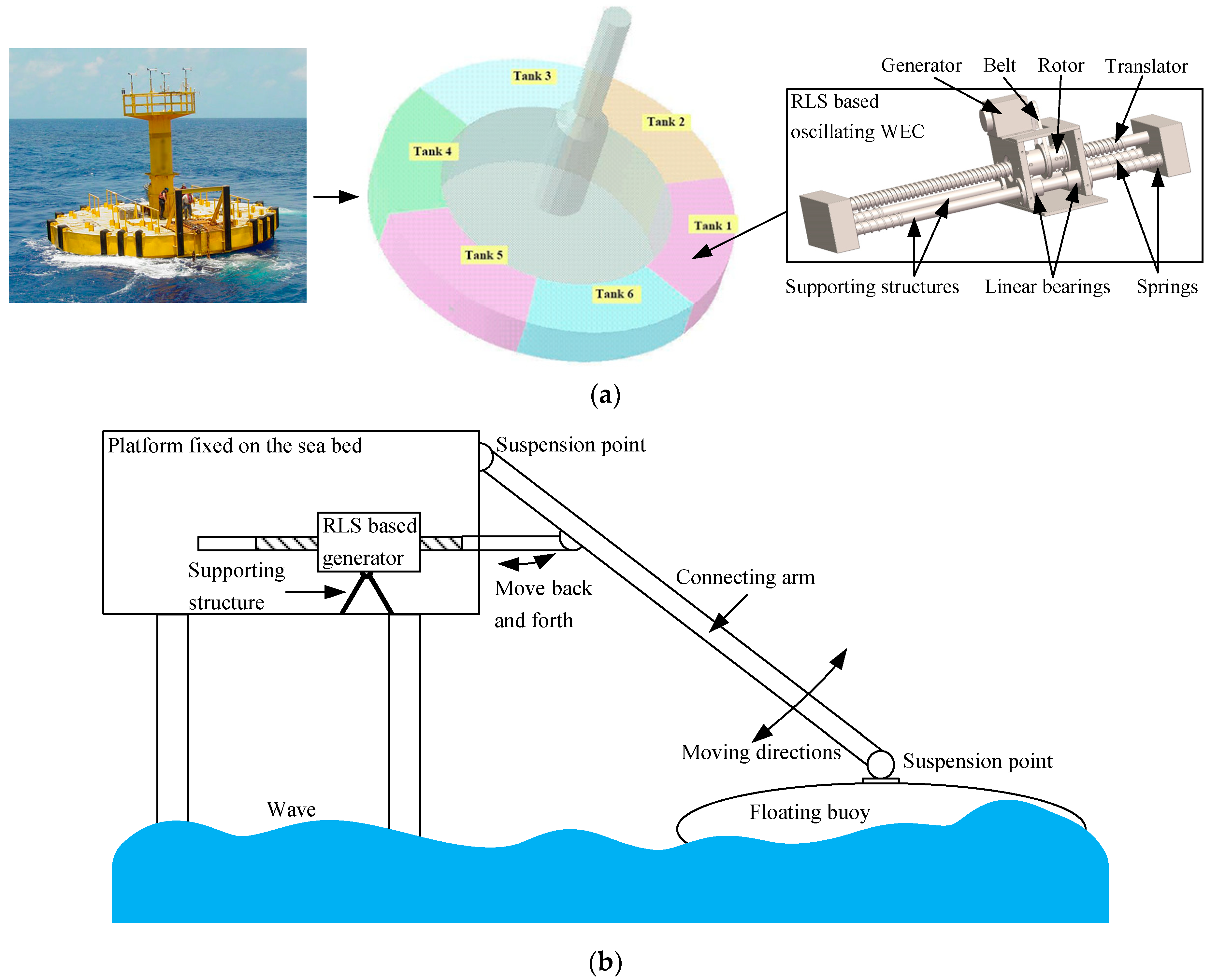
4.2. Potential Applications in WECs

Figure 16 depicts the potential applications of the RLS. Figure 16a shows the RLS-based oscillating WEC and Figure 16b shows the RLS-based heaving buoy WEC.
The power shortage always appears in hydro-meteorological buoy systems because the photovoltaic panel can only offer power in the sunshiny daytime, so an oscillating type WEC is designed and would be installed in the buoy cabins. As shown in Figure 16a, the buoy heaves in the waves, driving rotor into linear back and forth movement along the translator, then the linear movement is converted into rotary motion by the RLS rotor. Finally, the rotational motion is transferred to the generator by a belt. It should be noted that, during the back and forth movement of the RLS rotor, the generator would also be in the bidirectional rotational motion. In fact, it is possible that the RLS rotor keeps recoupling in one direction during the operation in severe sea conditions because of its inherent self-protection ability. This may introduce an undesired risk of damage to the supporting structures when the rotor hits the end of the translator. Therefore, springs are installed at both ends of its supporting structures to provide protection for RLS and ensure the safe operation of the oscillating WEC. Gravity is the main energy source of the RLS-based oscillating WEC, so the power rating is limited to several Watts.
In Figure 16b, an RLS-based heaving buoy WEC is presented. Wave energy is captured by the buoy and transferred to the RLS through the connecting arm. Then, the linear motion is converted into rotary motion by the RLS. Finally, the generator is driven by the rotary motion. It should be noticed that Figure 16b is just an attempt to provide an inspiring idea for potential applications of RLS, instead of offering a solution for constructing a real WEC system. Wave energy is captured by the floating buoy, so the power levels would be up to several kilowatts or tens of kilowatts, which is determined by the specific size of the buoy.
For the applications inside a 10 m buoy, the RLS translator length would be two meters. Hence, many magnet materials would be saved compared with the MLS. Comparisons between the RLS and MLS are shown in Table 2. It can be seen that although the PM consumption in RLS is much lower than that in the MLS, the RLS is still able to offer a higher maximum thrust force. In addition, at the same thrust force level, the rotor length of the RLS would be about three times that of the MLS, resulting in a reduction in the effective stroke length. Thus, RLS is not suitable for applications requiring a very large thrust force and short stroke length.

5. Conclusions

In this paper, a reluctance lead screw is proposed which aims to offer an alternative for magnetic geared transmissions. From the simulations, analyses, and comparisons, it can be concluded that the RLS can well reduce the PM consumptions. Though the maximum thrust force is not as high as that of the MLS, the RLS is still able to offer a satisfactory thrust force with a longer active length. More importantly, compared with the MLS at the same thrust force level, about 12% of PMs will be saved for the RLS, since the RLS has no magnets on its translator. More PMs will be saved in longer translator applications. In addition, a simple method for approximating the helical magnets by discrete PMs has been also proposed. Potential applications in WECs are presented in the end. An RLS-based WEC is under development in the laboratory, and we intend to harness the potential wave energy at a competitive cost.

Author Contributions

Author contributions, investigation, and writing—original draft, T.T.; resources, writing—review and editing, W.W. and K.L.; software and data curation, J.J.; supervision, L.Z. and F.B. All authors have read and agreed to the published version of the manuscript.

Funding

This research was funded by the National Natural Science Foundation of China, grant number 51477094.

Conflicts of Interest

The authors declare no conflict of interest.

References

  1. Mork, G.; Barstow, S.; Kabuth, A.; Pontes, M.T. Assessing the Global Wave Energy Potential. In Proceedings of the 29th International Conference on Ocean, Offshore and Arctic Engineering (OMAE), Shanghai, China, 6–11 June 2010; pp. 447–454. [Google Scholar]
  2. David, R. Power from the Waves; Oxford University Press: Oxford, UK, 1995. [Google Scholar]
  3. Symonds, D.; Davis, E.; Ertekin, R. Low-power autonomous wave energy capture device for remote sensing and communications applications. In Proceedings of the 2010 IEEE Energy Conversion Congress and Exposition, Atlanta, GA, USA, 12–16 September 2010; pp. 2392–2396. [Google Scholar]
  4. Curto, D.; Frazitta, V.; Trapanense, M. Designing an innovative system for sea wave utilization. In Proceedings of the OCEANS 2018 MTS/IEEE Charleston, Charleston, SC, USA, 22–25 October 2018; pp. 1–6. [Google Scholar]
  5. Hansen, R.H.; Andersen, T.O.; Pedersen, H.C. Model based design of efficient power take-off systems for wave energy converters. In Proceedings of the 12th Scandinavian International Conference on Fluid Power, Tampere, Finland, 18–20 May 2011; pp. 18–20. [Google Scholar]
  6. Carpita, M.; Beltrami, T.; Besson, C.; Gavin, S. Multiphase active way linear motor: Proof-of-concept prototype. IEEE Trans. Ind. Electron. 2011, 59, 2178–2188. [Google Scholar] [CrossRef]
  7. Cao, R.; Cheng, M.; Zhang, B. Speed control of complementary and modular linear flux-switching permanent-magnet motor. IEEE Trans. Ind. Electron. 2015, 62, 4056–4064. [Google Scholar] [CrossRef]
  8. Choi, S.Y.; Lee, C.Y.; Jo, J.M.; Choe, J.H.; Oh, Y.J.; Lee, K.S.; Lim, J.Y. Sub-Sonic Linear Synchronous Motors Using Superconducting Magnets for the Hyperloop. Energies 2019, 12, 4611. [Google Scholar] [CrossRef] [Green Version]
  9. Polinder, H.; Damen, M.E.; Gardner, F. Linear PM generator system for wave energy conversion in the AWS. IEEE Trans. Energy Convers. 2004, 19, 583–589. [Google Scholar] [CrossRef] [Green Version]
  10. Spooner, E.; Grimwade, J. SnapperTM: An efficient and compact direct electric power take-off device for wave energy converters. In Proceedings of the World Maritime Technology Conference, London, UK, 6–10 March 2006; pp. 6–10. [Google Scholar]
  11. Hussain, H.A. A Novel Contactless Rotary-to-Linear Magnetic Actuator. In Proceedings of the 2019 IEEE International Electric Machines & Drives Conference (IEMDC), San Diego, CA, USA, 12–15 May 2019; pp. 1081–1086. [Google Scholar]
  12. Liu, X.; Liu, Y.; Li, X. Parametric Analysis and Design of Magnetic Lead Screw. In Proceedings of the 2019 IEEE International Electric Machines & Drives Conference (IEMDC), San Diego, CA, USA, 12–15 May 2019; pp. 1990–1995. [Google Scholar]
  13. Holm, R.K.; Berg, N.I.; Walkusch, M.; Rasmussen, P.O.; Hansen, R.H. Design of a magnetic lead screw for wave energy conversion. IEEE Trans. Ind. Appl. 2013, 49, 2699–2708. [Google Scholar] [CrossRef]
  14. Ling, Z.; Zhao, W.; Ji, J.; Liu, G. Design of a new magnetic screw with discretized PMs. IEEE Trans. Appl. Supercond. 2016, 26, 1–5. [Google Scholar] [CrossRef]
  15. Lu, K.; Wu, W. Electromagnetic lead screw for potential wave energy application. IEEE Trans. Magn. 2014, 50, 1–4. [Google Scholar] [CrossRef]
  16. Wang, J.; Atallah, K.; Wang, W. Analysis of a magnetic screw for high force density linear electromagnetic actuators. IEEE Trans. Magn. 2011, 47, 4477–4480. [Google Scholar] [CrossRef]
  17. Ling, Z.; Zhao, W.; Ji, J.; Zhu, J.; Mao, J. Design and Analysis of a New HTS Electromagnetic Screw. IEEE Trans. Magn. 2017, 53, 1–4. [Google Scholar] [CrossRef]
  18. Gao, F.; Wang, Q.; Jibin, Z. Analytical Modeling of 3-D Magnetic Field and Performance in Magnetic Lead Screws Accounting for Magnetization Pattern. IEEE Trans. Ind. Electron. 2019, 67, 4785–4796. [Google Scholar] [CrossRef]
  19. Heya, A.; Nakata, Y.; Sakai, M.; Ishiguro, H.; Hirata, K. Force Estimation Method for a Magnetic Lead-Screw-Driven Linear Actuator. IEEE Trans. Magn. 2018, 54, 1–5. [Google Scholar] [CrossRef]
  20. Gao, F.; Wang, Q.; Hu, Y.; Chen, B.; Zhao, B. Performance Evaluation of Magnetic Lead Screws Equipped With Skewed Arc Magnets Instead of Helical Ones. IEEE Trans. Magn. 2018, 54, 1–5. [Google Scholar] [CrossRef]
  21. Pakdelian, S.; Frank, N.W.; Toliyat, H.A. Magnetic design aspects of the trans-rotary magnetic gear. IEEE Trans. Energy Convers. 2014, 30, 41–50. [Google Scholar] [CrossRef]
  22. Cirolini, M.; Flores Filho, A.F.; Wu, Y.C.; Dorrell, D.G. Design Aspects of a Reluctance-Based Magnetic Lead Screw. IEEE Trans. Magn. 2019, 55, 1–6. [Google Scholar] [CrossRef]
  23. Ling, Z.; Ji, J.; Wang, J.; Zhao, W. Design optimization and test of a radially magnetized magnetic screw with discretized PMs. IEEE Trans. Ind. Electron. 2017, 65, 7536–7547. [Google Scholar] [CrossRef]
  24. Zhao, A.; Wu, W.; Jiang, J.; Zhu, L.; Lu, K.; Blaabjerg, F. Design and experiment of a magnetic lead screw for the point-absorbing wave energy conversion system. IET Electr. Power Appl. 2020, 49, 618–626. [Google Scholar] [CrossRef]
Figure 1. Schematic view of traditional magnetic lead screw (MLS).
Energies 13 05388 g001
Figure 2. The proposed reluctance lead screw (RLS).
Energies 13 05388 g002
Figure 3. 2D symmetric view of the RLS.
Energies 13 05388 g003
Figure 4. Magnetic field distribution. (a) Stable state (aligned position), (b) unstable state (displaced axially by 3/5 pole pitch).
Energies 13 05388 g004
Figure 5. Physical meaning of the parameters shown in Table 1.
Energies 13 05388 g005
Figure 6. Variation in the thrust force with different axial displacements between the rotor and translator.
Energies 13 05388 g006
Figure 7. Variation in the maximum thrust force with different air gap radii.
Energies 13 05388 g007
Figure 8. Variation in the maximum thrust force and force per permanent magnet (PM) volume with different air gap lengths.
Energies 13 05388 g008
Figure 9. Comparisons of the maximum thrust force when the rotor is made from different materials.
Energies 13 05388 g009
Figure 10. The maximum thrust force and force per PM volume when the thread thickness varies from 1 to 10 mm.
Energies 13 05388 g010
Figure 11. Variation in the maximum thrust force with different rotor lengths.
Energies 13 05388 g011
Figure 12. Variation in the maximum thrust force and force per PM volume with different PM thicknesses.
Energies 13 05388 g012
Figure 13. Influences of different PM arc angles on the thrust force and torque.
Energies 13 05388 g013
Figure 14. Schematic view of the proposed PM arc and one-turn magnets formed by 8 PM arcs.
Energies 13 05388 g014
Figure 15. Rotor semi-cylinder, the final rotor installed with PMs, and the final RLS.
Energies 13 05388 g015
Figure 16. Two potential applications of RLS. (a) RLS-based oscillating wave energy converter (WEC). (b) RLS-based heaving buoy WEC.
Energies 13 05388 g016
Table 1. Initial parameters of the RLS.
ParameterQuantityUnit
Translator radius Rtl19mm
Translator length Ltl200mm
Rotor outer radius Rrto50mm
Rotor internal radius Rrti40mm
Rotor length Lrt80mm
magnet thickness hm10mm
Pole pitch τp10mm
Lead λ 40mm
Air gap g1mm
Thread width wi10mm
Thread thickness hi10mm
PM remanence Br1.1T
PM coercivity Hc838.0kA/m
Table 2. Comparisons in the RLS and MLS.
Parameters and UnitsRLSMLS
Translator radius/mm1918
Translator length/mm20002000
Rotor outer radius/mm5041
Rotor length/mm12036
Maximum Force/kN1.81.5
PM consumption/cm3131.91543.5
Publisher’s Note: MDPI stays neutral with regard to jurisdictional claims in published maps and institutional affiliations.

