Article

Comparative Analysis of the Mining Cribs Models Filled with Gangue

by
Krzysztof Skrzypkowski
Faculty of Mining and Geoengineering, AGH University of Science and Technology, Mickiewicza 30 av., 30-059 Kraków, Poland
Energies 2020, 13(20), 5290; https://doi.org/10.3390/en13205290
Submission received: 8 September 2020 / Revised: 7 October 2020 / Accepted: 10 October 2020 / Published: 12 October 2020
(This article belongs to the Special Issue Green Coal Mining Techniques 2020)

Abstract

:
In the article, comparative laboratory strength tests of three-point and four-point wooden cribs models are presented. In the case of cribs with a triangular cross-section, the notches made at an angle of 60 degrees were used for the first time. The individual beams of the three-point and four-point cribs were stacked horizontally and connected to each other by means of a quick-drying adhesive. The main aim of the research was to compare the empty models with cribs filled with a gangue. In order to better understand the mechanism of behavior of models under loads, load-displacement and pressure-compressibility characteristics are presented. It was found that filling the three-point and four-point crib with gangue increases its maximal load several times compared to the empty cribs.

1. Introduction

Contemporary underground mining is closely related to environmental protection through the use of waste rocks found in the heaps [1,2,3]. Rockfill is one of the oldest ways of filling post-exploitation spaces. Currently, this type of filling is widely used in the exploitation of hard coal, ores, and chemical raw materials. Yang et al. [4] stated that gangue backfilling mining technology constitute green mining technologies, especially to solve coal gangue emission. Li and Guo [5] and Sun et al. [6] revealed that filling the goaf area with gangue reduces the moving of rock mass. Cao et al. [7] presented wide strip backfilling method in order to control surface subsidence. Tai et al. [8] brought close mining technology of fully mechanized gangue backfilling with the connection of fully mechanized coal mining.
Filling the post-exploitation spaces with the application of rockfill is usually carried out by means of belt conveyors, self-propelled machines [9], scrapers [10], by gravity, and using compressed air pipelines. In Poland, gangue is used in the Legnica-Głogów Copper District of KGHM (Copper Mining and Smelting Complex) mines, especially for the room and pillar method with roof bending [11,12]. The waste rocks are delivered to the goaf using loading machines. Rockfill is very environmentally friendly, because waste rocks from preparatory and exploitation excavations can be directly used for backfilling, without having to remove them to the surface. In addition, it can be used in unconventional different operating conditions, when other methods of liquidation of goafs are impossible or technologically and economically burdensome. Considering the increase in depth, the use of rockfill has an advantage over hydraulic backfilling, whose installation must be able to withstand high pressure. Very often, to improve the strength parameters of rockfill, binding agents are added [13,14] and waste materials [15,16,17]. Tesarik et al. [18] and Emad et al. [19] informed about the application of cemented rockfill during pillar extraction in order to increase the stability of excavation.
However, it should be borne in mind that sometimes water from underground workings after the treatment process supplies cities with drinking water [20]. Considering the above criterion, the use of, for example, paste filling with the addition of fly ashes requires additional protection of excavations. In addition, operating costs and the hazard of mine water pollution increase significantly. Problematic issues related to rockfill are associated with, among others: dustiness in the forehead; the need to guarantee a continuous supply of waste rocks with massive use; compressibility, which in some cases can reach close to 50%; and difficulties in organizing transport over long distances.
Wooden crib support is commonly used to strengthen roadway and rooms [21,22,23]. Zhao [24] presented typical standing supports together with the wooden cribs used for gob-side entry retaining technology. The bearing capacity of a wooden crib increases with the increases of convergence [25,26]. In Polish ore mining, wooden cribs are used to strengthen rooms at the stage of cutting technological pillars and as a local support [27]. In South African underground ore mines depending on the ground conditions, wooden support is widely used in three different support systems: grout packs, crush pillar, and timber props [28]. Erasmus and Smit [29] stated that external support structures, such as timber packs or cribs, form a vital part of the support regime in a reef or seam type of mining operations. Piennar and Howell [30] stated that the new-generation timber packs can safely be used in seismically active areas.
Due to the huge amounts of waste rocks formed in underground ore mining as well as large spaces after exploitation, the author of the article conducted model tests of the three-point and four-point wooden cribs filled with gangue, indicating that they are an excellent way in order to waste management in the mining wooden support.

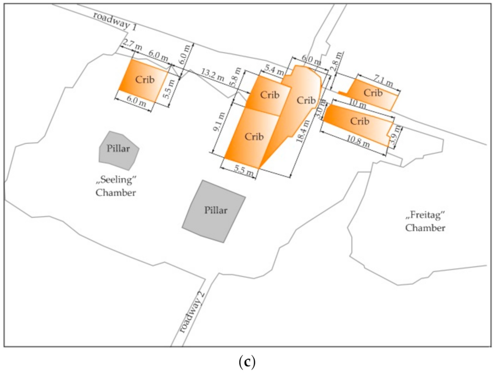
2. Wood and Cribs in Polish Mining

Wood as a material for supporting underground workings has been known and used in mining practice for a long time. Initially, as the only and basic type of support, it has lost its original meaning over the years, but nowadays it is very often a form of additional protection of workings [31]. Compared to other materials used in underground construction, wood has a number of positive properties, such as compressive strength, bending and flexibility, relatively low volume weight, and easy processing with simple tools, and thus the ability to quickly produce a support structure adapted to local conditions. The wooden support is of particular importance during the reconstruction of the collapses and in all kinds of rescue operations, where there is a need to quickly reach the cut-off areas in the mine through collapsed or endangered with collapses. The advantages of the wooden support include its ability to warn miners about increased pressure in the face, which is manifested by a characteristic crack. Recently, wood has been used in underground construction as an auxiliary material for all kinds of roadways [32], room, and stopes [33], partly in some mining excavations: longwall faces, strip, and room and pillar methods [34]. In shaft construction, wood is used to make inter-level shafts or shallow shafts with a rectangular cross-section. The following types of wood are used in Polish mining: pine, spruce, beech, oak, fir, and larch. The above-mentioned advantages and versatility of use put aside the disadvantages of wood, which include short service life, low durability, susceptibility to decay, and flammability. A common disadvantage of all types of wood is its tendency to absorb moisture and evaporate it when heated, which causes cracks. Increasing the humidity of the wood leads to its rotting, and also has a negative effect on its mechanical strength. Wood is protected against rotting and decaying with a layer of tar, asphalt, or concrete; carbonization of the surface layer by burning; and also by impregnation with special anti-rot preparations [35]. The wood used in the construction of mining support is exposed primarily to compressive and bending forces, and to a lesser extent to shear and tensile forces. The basic strength parameters of wood, i.e., an anisotropic material, are closely related to the direction of external forces. The direction of the force may be parallel, perpendicular to the fiber, radially, and perpendicular to the fiber, tangentially. The compressive strength along the fibers is higher than that across the fibers (Table 1).
One of the significant problems in the Polish national wood economy is the problem of the increasing shortage of wood every year. Therefore, introducing, among others, in mining technology, the most economical and rational use of this material by extending its service life (by impregnation) or replacing it with other materials (steel, concrete, brick, prefabricated elements, plastics) is fully justified and necessary. The ideal solution to this issue would be to replace wood with appropriate plastic materials, the properties of which would coincide with the advantages of wood and eliminate its negative features. The main obstacle at the present stage of the development of plastics chemistry are economic considerations and the relatively high unit cost of a new material compared to wood [37]. Therefore, wood will be used in mining for many years to come as a valuable and in many cases irreplaceable material.
The history of using wooden cribs in Polish salt mining dates back to the 13th century [38,39]. Full, openwork, empty, or filled cribs fulfill their role for centuries. The support of tourist and sanatorium excavations that occur in the Bochnia and Wieliczka Salt Mines is not only to preserve the stability of the excavation but also to preserve the monument of Polish culture as well as the evidence of the development of Polish mining. Currently, the Wieliczka and Bochnia Salt Mines serve only as a tourist and sanatorium. Wooden support in the form of cribs (Figure 1a–c) and props and long rock bolts made from glass-reinforced plastic constitute the basic method of protection of the salt excavations.
Another example of the wooden support, including wooden cribs, is the zinc and lead Olkusz-Pomorzany mine. Ore deposits in the Olkusz region in Poland occur in the form nest (Figure 2a) and lenses (Figure 2b). For irregularly lying deposits, the exploration drift grid is 100 m. The exploitation is carried out in a layer of ore-bearing dolomites with a thickness of about 40 m, at a depth of 80 to 120 m. The basic ore minerals are galena and sphalerite (Figure 2c). In the Olkusz-Pomorzany mine, room and pillar and also strip methods are used. The orebody is mined using explosives (emulsion materials: emulinit). The length of the blasting holes is from 2 to 3 m. The number of holes on the forehead with a cross-section of 25m2 is from 25 to 50. The excavations are secured with a resin rock bolt support with a length of 1.6 m. The post-mining areas are filled with a sand hydraulic filling. The average content of zinc and lead in the deposit is 2.6% and 1.3%, respectively. In 2019, production was at the level of 1.6 million tons. In the Olkusz-Pomorzany mine, the thick deposit is divided into horizontal layers parallel to each other with a thickness of 5 to 6 m. In the first layer, the room and pillar is always used, and in the following layers, the strip method. The strip method is used to mine orebodies with a variable thickness and mineralization with the inclination up to 20° and a thickness of up to 6 m. In the exploitation field, operational pillars 35 or 70 m wide are separated, for unidirectional and bidirectional exploitation (Figure 3a). From the raise gallery, the deposit is mined with a strip with a width and height from 5 to 6 m. The strip method is used in two variants with a barrier pillar and a side dam. In the case of roof rocks with a compressive strength above 50 MPa, the barrier pillar variant is used. For this variant, after mining the strip, the barrier pillar is exploited, starting from the end of the strip (Figure 3b). The maximum strip width is 10 m. To eliminate the phenomenon of sand slipping from the next strip, light canvas dams are used. For roof rocks with compressive strength below 50 MPa, the side dam variant is used. After mining a strip, a wooden filling dam is built along the strip sidewall, at intervals of about 0.8 m from the strip sidewall (Figure 3c). The dam provides additional roof support. In addition to the side dam, a front dam is being built (Figure 3d) with a hole to drain water. Sometimes, wooden cribs are placed next to the sidewall in order to strengthen the room and roadway excavation (Figure 3e). Backfilling begins at the front of the strip and continues continuously until complete filling. Next strips are mined one next to the other, alongside of side wooden dams.

3. Compressibility of the Gangue

In the laboratory tests, gangue was taken from the discharge grate of zinc and lead Olkusz-Pomorzany mine in Poland from a depth of 100 m (Figure 4a). It is worth mentioning that in this mine, rock pieces after blasting have an average diameter of 0.4 m. In order to fill the wooden cribs models, gangue was specially crushed. The average diameter was 0.018 m (Figure 4b). Li et al. [40] and Xiao et al. [41] studied rock material with similar granulation to dry filling. Subsequently, gangue (dolomitic limestone) was placed in oedometers (Figure 4c–d) in order to determine the compressibility. The test results are presented in Figure 5. The internal and outer diameter of the oedometer was 0.113 and 0.150 m, respectively. The diameter and height of the piston was 0.113 and 0.210 m, respectively. The compressibility of the crushed gangues was calculated according to the following formula [42]:
C = h b h a h b · 100 % ,
where:
  • C—compressibility/%,
  • hb—height of the gangues in an oedometer before test/mm,
  • ha—height of the gangues in an oedometer after test/mm.
Based on Figure 5, it can be drawn that at a pressure from 0.85 to 1.1 MPa, the compressibility of gangue is 10%. To achieve 20% compressibility, there must be a pressure that ranges from 3.5 to 4.7 MPa. However, the pressure ranges from 11 to 15 MPa corresponds to a compressibility of 30%. At present, exploitation in the zinc and the lead Olkusz-Pomorzany mine is carried out at a depth of 100 m. Assuming that the average unit weight of overburden is 2.7 Mg/m3, then the vertical pressure is about 2.7 MPa. For this pressure value, the compressibility range is between 15.2% and 18.4%.

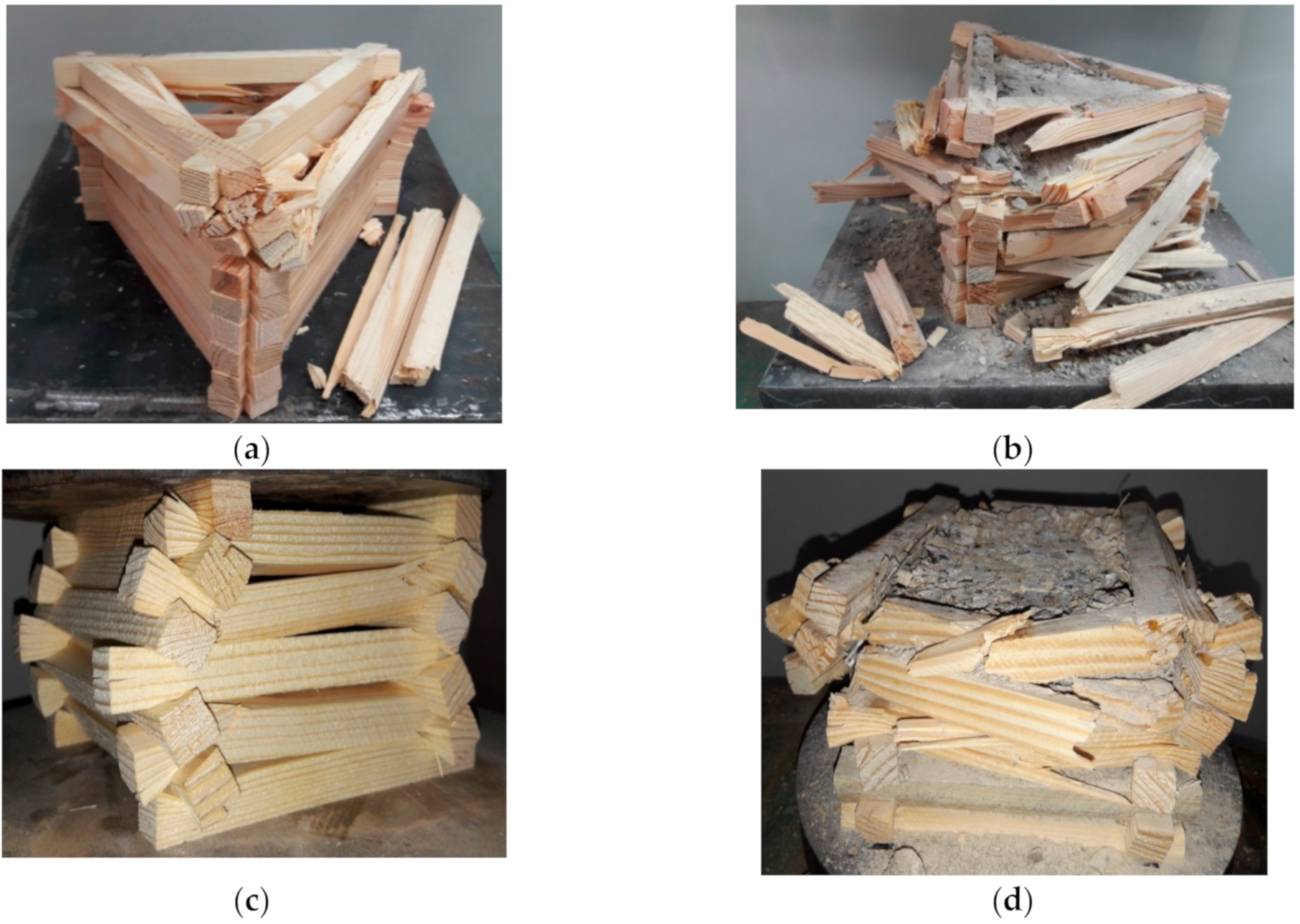
4. Laboratory Tests of Wooden Cribs Models

Laboratory tests were carried out at the AGH University of Science and Technology, Faculty of Mining and Geoengineering in Poland. The tests were carried out on a hydraulic testing machine with a manual hydraulic oil flow valve. In order to determine the load-displacement characteristics, specialized measuring equipment was used. All sensors were certified and marked by the manufacturer. Three strain gauge force sensors were used to measure the load, while an incremental cable encoder was used to measure the displacement. The individual sensors were connected to a measuring amplifier, which was connected to the computer via an internet cable. The computer was equipped with a specialized CatmanEasy program, with the help of which the load and displacement of the tested crib model were monitored on an ongoing basis. The measurement results were saved in ASCII format and in the Excell program, which was used to draw the load-displacement characteristics. On the laboratory station, three-point and four-point wooden cribs made of pine wooden beams with a triangular and square cross-section were used. The beams of the triangular crib had special notches, made at an angle of 60 degrees. The purpose of the notches was to connect adjacent beams (Figure 6). The individual beams were joined together by quick-drying adhesive. The setting time of the adhesive was 30 s. The height of three-point crib model was 0.180 m while the four-point was 0.150 m. Wooden beams, after appropriate cutting, were dried and had a humidity of 8% to 10%. For the construction of three-point and four-point wooden cribs, models used beams with dimensions of 0.2 m × 0.015 m × 0. 015 m and 0.15 m × 0.015 m × 0.015 m, respectively (Figure 7a–l). Models of three-point and four-point cribs were built of 36 and 20 beams, respectively. In addition, three-point and four-point cribs were filled with gangues (dolomitic limestone) (Figure 7d–f,j–l), with an average diameter 0.018 m. Dolomitic limestone was characterized by compression strength equal to 30 MPa [43]. Only for the four-point wooden cribs models, fiber glass building mesh as an inside lining with a dimension 0.005 m was additionally used.
The three-point models did not use an internal mesh as the crib beams were adjacent to each other.
The results of the compression tests are presented in Table 2 and in Figure 8a–d and in Figure 9a–d.
Based on Figure 9a–d, it can be drawn that up to maximal load, stiffness for the empty three-point wooden cribs models is 0.72 mm/kN, which means that it is 0.46 higher compared to four-point empty cribs. Comparing empty three-point and four-point cribs with cribs filled with gangue; it can be stated that the stiffness difference is 0.61 and 2.38 kN/mm, respectively. On the other hand, four-point filled models of cribs show much greater stiffness compared to the three-point filled models with gangue; the difference is as much as 1.31 kN/mm. In the process of compression wooden models of cribs, two characteristic failure models can be distinguished; compression until the material is destroyed and compression combined with bending of the crib beam. The first model relates to empty cribs, in which, in the first stage of compression, individual beams are fitted to each other, it is also related to the deletion of clearances between individual beams. Then, the beams of the crib are deformed; the beams press into each other. In the last stage of compression, the crib transfers the load until the wood delaminates and, consequently, leads to breakage of the beams and destruction of the crib structure. The second model of failure relates to the cribs filled with gangue. Compared to the empty cribs, it can be seen that the first compression step consists in eliminating the clearances between the crushed gangue and clamping the crib beams. As a result of the load increase, irregular pieces of the gangue press against the crib beams. In particular, free spaces between the beams are exposed to surface pressure. Due to these pressures, the wood is weakened, the beams break, which in turn leads to the combined process of bending and compressing the crib. This combined process continues until the gangue spills out.

5. Discussion

One the purposes of the research was the use of gangue; therefore, additionally, pressure-compressibility characteristics for three-point and four-point wooden cribs filled with gangue were made in this study (Figure 10a,b). Calculations of pressure and compressibility were made in the Excel spreadsheet by creating a special formula using the results of loading and displacement of the examined cribs. The pressure value was calculated as the ratio of the load to the surface area of the wooden crib models filled with gangue. The surface area was taken into account, in accordance with the dimensions shown in Figure 7e,k. On the other hand, the value of compressibility was calculated as the value of the displacement increase to the initial height of the crib; the result obtained was multiplied by 100%. The value of compressibility was calculated up to the value of 50%, bearing in mind that the three-point cribs achieved compressibility only up to 40%. Above this range, the three-point cribs were completely destroyed. The wooden crib models were tested under static load. The loading rate was 0.5 kN/s.
Based on Figure 10a,b, it can be concluded that for four-point cribs, much less pressure is needed than for three-point cribs. For the specified value of compressibility, the average value of pressure from five measurements was calculated. Then, the obtained results for four-point and three-point cribs were compared with each other, indicating the range of the variability. The difference in favor of the four-point crib is 0.725, 1.99, 2.31 and 1.35 MPa, in relation to 10%, 20%, 30%, and 40% of compressibility, respectively. Based on the obtained results, it can be concluded also that the four-point crib has significantly better strength parameters compared to the three-point crib, for which the fifth compressibility range can be marked (Figure 10b).
Potential directions for the use of wooden cribs filled with gangue could be used in the strip mining methods in the Olkusz-Pomorzany mine. Due to the shallow exploitation depth of about 100 m, the vertical pressure is about 2.7 MPa. Moreover, taking into account the fact that the exploitation of a part of the deposit is carried out in an undeveloped area and the lack of natural hazards, this means that the post-mining space can be developed with wooden cribs filled with the gangue. On the basis of the obtained results of the compressibility of the wooden cribs, it can be concluded that for the pressure equal to 2.7 MPa, the average compressibility is 17% and 30%, respectively, for the three-point and four-point cribs. Taking into account the fact that in industrial conditions, the value of the cribs’ deformation is much greater, and the range of compressibility would also be increased from a few to a dozen percent [25]. This is due to the scale effect of the tested samples [44]. Since the models of four-point cribs filled with gangue were characterized by more than twice the load-bearing capacity (Table 2) compared to three-point cribs, the more favorable model in terms of strength was selected for the analysis of the scale effect. An example of the application of the model tests of wooden cribs in industrial conditions is the underground hard coal mine LW Bogdanka S.A. in Poland. On the basis of the model tests of beech wooden cribs with different filling [45], wooden cribs were built in the mine, which were used to reinforce the maingate behind the longwall face [46]. As a result of the use of additional maingate strengthening, the convergence of the excavation was reduced by 20-30%. In this research, the scale effect was taken into account according to Weibull’s theory [47], which shows that the strength of an element depends on its volume, which is expressed by the relationship:
R 1 R 0 = V 0 V 1 1 m ,
where:
  • R1—predicted compressive strength of the crib filled with gangue on a geometric scale 1:1;
  • R0—compressive strength of the four-point wooden crib model filled with gangue;
  • V0—volume of the four-point wooden crib model filled with gangue;
  • V1—predicted volume of the crib filled with gangue on a geometric scale 1:1;
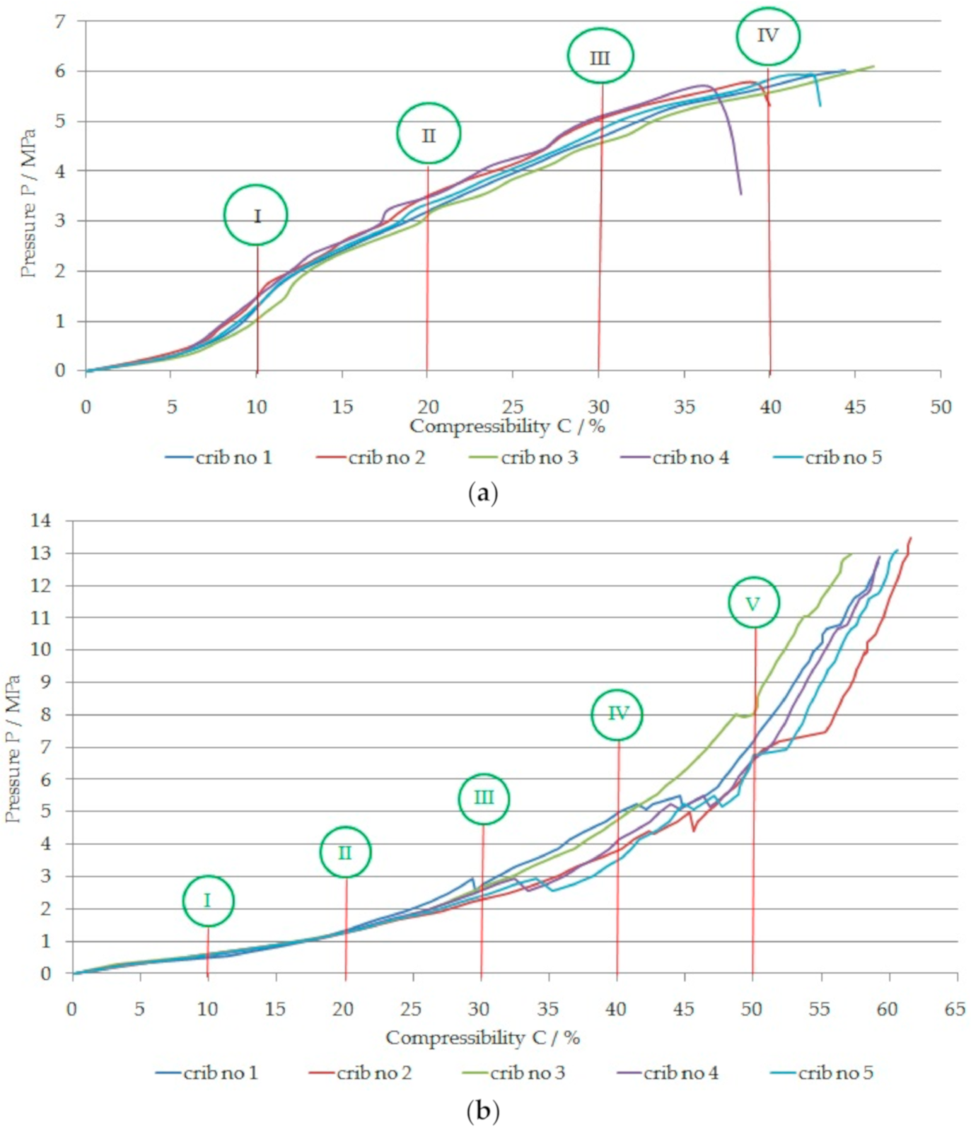
  • M—Weibull modulus; it can be estimated from the formula [44]:
    m = 1.2 C V ,
    where Cv is the coefficient of variation of the strength of the material, defined as the ratio of the standard deviation to the average value. It was assumed in this study that the volume of the four-point wooden crib model filled with waste rocks was 0.00150 m3 (Figure 7k–l); the average compressive strength determined experimentally under laboratory conditions for 10%, 20%, 30%, 40%, and 50% of compressibility is equal to 0.6, 1.4, 2.55, 4.25, and 7.31 MPa, respectively (Figure 10b). Taking into account that vertical stress in the mine is about 2.7 MPa, as the convergence of the excavation increases, the compressibility of the wooden cribs will increase, contributing to the improvement of stability conditions. Currently, in the Olkusz-Pomorzany mine, wooden cribs with round beams, as shown in Figure 3e, are used. Due to the fact that the exploitation in the aforementioned mine is carried out at a shallow depth of about 100 m below the ground surface and that there are no tremors or roof fall rocks in the mine (according to the research carried out by an expert for the support of mining excavations, it is possible to leave the rooms and roadways without a rock bolt support [48]), I performed model tests of wooden cribs indicating the possibility of their future consideration for use. The predicted volume of the wooden crib filled with gangue on a geometric scale of 1: 1 will be 205.78 m3, a material strength coefficient of variation (for models of cribs filled with gangue and compressive strength of 0.6, 1.4, 2.55, 4.25, and 7.31 MPa, respectively): Cv = 0.196, 0.084, 0.046, 0.083, 0.064, and Weibull modulus m is equal: 6.122, 14.285, 25.97, 14.45, and 18.75, respectively. Taking into account the above data, the predicted compressive strength of the wooden cribs filled with waste rocks on a geometric scale 1: 1 will be 0.09, 0.61, 1.62, 1.87, and 3.88 MPa for compressibility 10%, 20%, 30%, 40%, and 50%, respectively.
Comparing two technologies of liquidation of the post-mining spaces: wooden cribs filled with gangue and hydraulic backfill for the strip method, it can be stated that the total costs for wooden cribs will be significantly lower. The total costs associated with the use of hydraulic backfill can be expressed by the following formula:
T 1 = b 1 + b 2 + b 3 + b 4 + b 5 + b 6 + b 6 + b 7 +   b 8 + b 9   /   PLN ,
where:
  • b1—cost of filling material (sand)/PLN;
  • b2—cost of transporting of filling material /PLN;
  • b3—material cost of the filling pipeline /PLN;
  • b4—cost of the medium (water) transporting filling material /PLN;
  • b5—cost of construction the filling dams /PLN;
  • b6—energy costs associated with pumping out filling water /PLN;
  • b7—cost of building wooden dams with canvas /PLN;
  • b8—cost associated with taking the gangue to the surface /PLN;
  • b9—cost related to the storage of gangue on the surface /PLN.
However, the costs associated with the use of wooden cribs filled with gangue can be expressed by the following formula:
T 2 = w 1 + w 2 + w 3 +   w 4   /   PLN ,
where:
  • w1—material cost (wood for building cribs: either fresh or obtained from old railway sleepers)/PLN;
  • w2—cost of transporting wooden cribs,/PLN;
  • w3—costs of building wooden cribs,/PLN;
  • w4—costs of transport of gangue from the mining department to the strips,/PLN.
For wooden cribs filled with gangue, energy costs associated with pumping and draining water will be eliminated. It is worth noting that in the zinc and lead Olkusz-Pomorzany mine, the most energy-consuming and at the same time cost-intensive process is associated with pumping water into surface. The inflow of water is about 200 m3/min [49]. In order to minimize the costs associated with the use of gangue, it would be necessary to conduct separate mining, that is separate the gangue and orebody with valuable ore minerals, provided that the limitation of the presence of mineralization is clearly marked, as in Figure 2c. In the case of exploratory works in the waste rocks (Figure 2a,b), then there is no need to take it to the surface, but it must be transported directly to the strips.
An exemplary strip mining method for a zinc and lead ore deposit with wooden cribs filled with gangue is shown in Figure 11. The strip mining method can be divided into three stages. In the first stage (Figure 11a), the ore is mined in two directions, leaving a continuous inter-room pillars between the mining rooms. In the second stage, the mined ore deposit is filled with wooden cribs filled with gangue and then the inter-room pillars are mined on both sides (Figure 11b). In the third stage, wooden cribs are again built in the empty spaces and filled with gangue (Figure 11c).
One point to be considered in an inclined orebody is the forces acting on the crib (Figure 12). The values of individual forces were calculated according to the following formulas:
F 1 =   γ · H · a + l · b + l · cos α ,
F 2 =   c · γ · H · a + l · b + l · cos α ,
N 1 =   γ · H · a + l · b + l · cos 2 α ,
N 2 =   c · γ · H · a + l · b + l · sin 2 α ,
T 1 =   1 2 · γ · H · a + l · b + l · cos 2 α ,
T 2 =   1 2 · c · γ · H · a + l · b + l · sin 2 α ,
where:
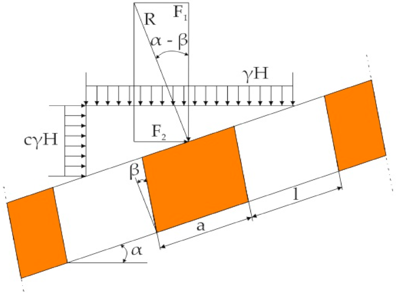
  • F1, F2—vertical and horizontal force, respectively/N;
  • N1, T1, N2, T2—components of vertical and horizontal forces (normal and shear loads), respectively /N;
  • γ—density of adjacent rocks/N/m3;
  • H—foundation depth of the crib/m;
  • l—strip width along the dip/m;
  • a—crib width along the dip/m;
  • l′—strip width along the strike/m;
  • b—crib width along the strike/m;
  • α—inclination angle of the orebody/°;
  • c—horizontal expansion factor (for geological conditions of the Olkusz-Pomorzany mine, c = 0.5).
By solving the system of forces and taking into account the surface of the cribs, the formulas for the value of average normal (σ) and shear (τ) stresses are obtained:
σ =   γ · H · S s · cos 2 α + c · sin 2 α ,
τ =   1 2 · γ · H · 1 c · S s · sin 2 α ,
where:
  • S—roof area per crib /m2;
  • S—crib surface /m2.
The compressive and shear strength of the crib between the strips should meet the condition:
s S   γ · H · cos 2 α + c · sin 2 α k c ,
s S   γ · H · 1 c · sin 2 α 2 · k t ,
where:
  • kc—allowable compressive stress/MPa;
  • kt—allowable shear stress/MPa.
In inclined orebodies, cribs should be tilted from the direction perpendicular to the roof and the floor of the strip towards the rise (Figure 13). Then, the concentration of compressive stresses is reduced and, consequently, the load capacity of the crib increases. The optimal angle of deflection β can be found according to the equation:
β = α arctg · c · tg α ,
where:
  • β—optimal angle of deflection (for α = 20°; β = 10°)/°;
  • arctg—inverse tangent;
  • α—inclination angle of the orebody/°.
The value of the resultant force (R) can be obtained by solving the system of forces shown in Figure 13:
R = c · γ · H · S · sin α sin α β .
Normal stresses in the section perpendicular to the axis of the crib can be calculated according to the formula:
  σ   = R s · cos β = γ · H · S s · c · sin α cos β · sin α β .
Assuming that the normal stresses are to be less than the allowable stresses in compression, we get:
s S γ · H · c · sin α cos β · sin α β k c .
Analyzing Formulas (12) and (19), it can be seen that they are similar to those for horizontally located orebodies (Formula (20)):
s S γ · H C s ,
where:
  • Cs—compressive strength of the crib /MPa.
Expressions in these formulas:
cos 2 α + c · sin 2 α = k α ,
and:
c · sin α cos β · sin α β = k α ,
where:
  • kα—factor of orebody inclination (for square cribs along the strike and along the dip, kα is equal 0.97 and 0.94 [50], respectively for α = 20°).
Inclined cribs show less load capacity than horizontal cribs. The dimensions of the inclined cribs can therefore be determined by the formulas given for horizontal orebodies, introducing into them the factor of orebody inclination kα, determined by Formulas (21) and (22).

6. Conclusions

Based on the laboratory research, it can be drawn:
  • Three-point empty wooden crib models have a higher load capacity of over 30% compared to the four-point crib.
  • Filling the three-point crib made of 36 beams filled with gangue increases its load capacity by more than twice.
  • Filling the four-point crib made of 20 beams filled with gangue increases its load capacity by over nine times.
  • The four-point wooden crib filled with gangue has a load capacity greater by 57% compared to the filled three-point wooden crib.
Underground ore mining continues to progress to deeper levels. The transport of excavated output and waste rocks contributes to increased production costs. A solution that has been used for a long time in mining technologies is the management of waste rock in both exploitation and preparatory excavations. At the intersection of excavations, where sidewalls are damaged very often, using three-point or four-point wooden cribs can be a quick and effective method of ensuring the stability of the excavation. Comparing the two types of crib connections, it should be stated that in mining conditions, the best solution would be to use four-point cribs due to the simple way of laying the beams. Moreover, considering the possibility of monitoring the load on the cribs, the four-point crib also has an advantage over the three-point crib as it is possible to place the sensor between the lower and upper crib beam at any height. Additionally, by filling the crib with waste rock, its condition can be macroscopically observed. Taking into account the amount of gangue that could be utilized in the crib (Figure 7e,k), it should be stated that the four-point crib creates much more favorable conditions. Its surface area for gangue management is 58% larger compared to the three-point crib. This means that to use the same amount of gangue, almost twice as many three-point cribs as four-point cribs should be used. The obtained results of laboratory tests may be helpful in making a decision on the method of securing the excavation with the simultaneous placement of gangue.

Funding

This research was prepared as part of AGH University of Science and Technology in Poland, scientific subsidy under number: 16.16.100.215.

Conflicts of Interest

The author declares no conflict of interest.

References

  1. Chang, Q.; Chen, J.; Zhou, H.; Bai, J. Implementation of Paste Backfill Mining Technology in Chinese Coal Mines. Sci. World J. 2014, 2014, 1–8. [Google Scholar] [CrossRef] [PubMed]
  2. Zhang, J.; Li, M.; Taheri, A.; Zhang, W.; Wu, Z.; Song, W. Properties and Application of Backfill Materials in Coal Mines in China. Minerals 2019, 9, 53. [Google Scholar] [CrossRef] [Green Version]
  3. Yildiz, T.D. Waste management costs (WMC) of mining companies in Turkey: Can waste recovery help meeting these costs? Resour. Policy. 2020, 68, 1–17. [Google Scholar] [CrossRef]
  4. Yang, G.-L.; Yang, R.-S.; Tong, Q.; Huo, C. Coalmine Green Mining with Gangue Backfilling Technique. Procedia Environ. Sci. 2011, 10, 1205–1209. [Google Scholar] [CrossRef] [Green Version]
  5. Li, H.; Guo, G. Surface Subsidence Control Mechanism and Effect Evaluation of Gangue-Backfilling Mining: A Case Study in China. Geofluids 2018, 2018, 1–9. [Google Scholar] [CrossRef]
  6. Sun, G.; Feng, T.; Liu, J. Survey on roof movement of the gangue backfill working face. J. Vibroeng. 2019, 21, 1107–1115. [Google Scholar] [CrossRef]
  7. Cao, W.; Wang, X.; Li, P.; Zhang, D.; Sun, C.; Qin, D. Wide Strip Backfill Mining for Surface Subsidence Control and Its Application in Critical Mining Conditions of a Coal Mine. Sustainability 2018, 10, 700. [Google Scholar] [CrossRef] [Green Version]
  8. Tai, Y.; Han, X.; Huang, P.; An, B. The mining pressure in mixed workface using a gangue backfilling and caving method. J. Geophys. Eng. 2019, 16, 1–15. [Google Scholar] [CrossRef]
  9. Ran, J.J. Safe mining practices under wide spans in underground non-caving mines—Case studies. Int. J. Min. Sci. Technol. 2019, 29, 535–540. [Google Scholar] [CrossRef]
  10. Yin, Y.; Zhao, T.; Zhang, Y.; Tan, Y.; Qiu, Y.; Taheri, A.; Jing, Y. An Innovative Method for Placement of Gangue Backfilling Material in Steep Underground Coal Mines. Minerals 2019, 9, 107. [Google Scholar] [CrossRef] [Green Version]
  11. Skrzypkowski, K. Case Studies of Rock Bolt Support Loads and Rock Mass Monitoring for the Room and Pillar Method in the Legnica-Głogów Copper District in Poland. Energies 2020, 13, 2998. [Google Scholar] [CrossRef]
  12. Skrzypkowski, K.; Korzeniowski, W.; Zagórski, K.; Zagórska, A. Modified Rock Bolt Support for Mining Method with Controlled Roof Bending. Energies 2020, 13, 1868. [Google Scholar] [CrossRef] [Green Version]
  13. Lingga, B.A.; Apel, D.B. Shear properties of cemented rockfills. J. Rock Mech. Geotech. Eng. 2018, 10, 635–644. [Google Scholar] [CrossRef]
  14. Jiang, H.; Fall, M.; Li, Y.; Han, J. An experimental study on compressive behaviour of cemented rockfill. Constr. Build. Mater. 2019, 213, 10–19. [Google Scholar] [CrossRef]
  15. Skrzypkowski, K.; Korzeniowski, W.; Poborska-Młynarska, K. Binding capability of ashes and dusts from municipal solid waste incineration with salt brine and geotechnical parameters of the cemented samples. Arch. Min. Sci. 2018, 63, 903–918. [Google Scholar] [CrossRef]
  16. Korzeniowski, W.; Poborska-Młynarska, K. Skrzypkowski, K. The idea of the recovery of municipal solid waste incineration (MSWI) residues in Kłodawa Salt Mine S.A. by filling the excavations with self-solidifying mixtures. Arch. Min. Sci. 2018, 63, 553–565. [Google Scholar] [CrossRef]
  17. Liu, W.; Xu, J.; Zhu, W.; Wang, S. A novel short-wall caving zone backfilling technique for controlling mining subsidence. Energy Sci. Eng. 2019, 7, 2124–2137. [Google Scholar] [CrossRef] [Green Version]
  18. Tesarik, D.R.; Seymour, J.B.; Yanske, T.R. Long-term stability of a backfilled room-and-pillar test section at the Buick Mine, Missouri, USA. Int. J. Rock Mech. Min. 2009, 48, 1182–1196. [Google Scholar] [CrossRef]
  19. Emad, M.Z.; Mitri, H.; Kelly, C. Dynamic model validation using blast vibration monitoring in mine backfill. Int. J. Rock Mech. Min. 2018, 107, 48–54. [Google Scholar] [CrossRef]
  20. ZGH Bolesław. Available online: https://www.zghboleslaw.pl (accessed on 21 September 2020).
  21. Timrite. Available online: http://www.timrite.co.za//products (accessed on 29 July 2020).
  22. Stratawordwide. Available online: https://www.strataworldwide.com/timber-roof-supports (accessed on 29 July 2020).
  23. Miningproducts. Available online: http://www.miningproducts.co.za/mining-products.html (accessed on 29 July 2020).
  24. Zhao, H. State-of-the-art of standing supports for gob-side entry retaining technology in China. J. S. Afr. Inst. Min. Metall. 2019, 119, 891–906. [Google Scholar] [CrossRef]
  25. Skrzypkowski, K. Decreasing mining losses for the room and pillar method by replacing the inter-room pillars by the construction of wooden cribs filled with waste rocks. Energies 2020, 13, 3564. [Google Scholar] [CrossRef]
  26. Korzeniowski, W.; Skrzypkowski, K.; Szumiński, A.; Zagórski, K. Laboratory investigations of the load capacity and load-strain characteristics of four-point cribs filled with waste rocks. Bull. Inst. Non-Ferrous Metals. 2015, 60, 303–308. [Google Scholar] [CrossRef]
  27. Skrzypkowski, K. The influence of dimension of mining crib model filled by waste rock on the course of load–displacement characteristic. Bull. Min. Energy Econ. Res. Inst. Pol. Acad. Sci. 2017, 99, 131–141. [Google Scholar]
  28. Ozbay, M.U.; Ryder, J.A.; Jager, A.J. The design of pillar systems as practiced in shallow hard-rock tabular mines in South Africa. J. S. Afr. Inst. Min. Metall 1995, 1/2, 7–18. [Google Scholar]
  29. Erasmus, P.N.; Smit, J. Assessment of Precast Cellular Lightweight Concrete (C.L.C.) Support Structures. In Proceedings of the International Symposium on Ground Support; Villaescusa, E., Windsor, C.R., Thompson, A.G., Eds.; Taylor & Francis Group: Kalgoorlie, Australia; Rottedram, The Netherlands, 1999; pp. 349–357. [Google Scholar]
  30. Pienaar, F.R.P.; Howell, M. The Rapid Loading of Packs. SANIRE Free State Symposium 2007. Redefining the Boundaries Part II; South African National Institute of Rock Engineering: Johannesburg, South Africa, 2007; pp. 1–10. [Google Scholar]
  31. Skrzypkowski, K. Strengthening the room excavation through the use of additional support in the form of wooden props in underground ore copper mines. Ores Non-Ferr. Met. Recycl. 2017, 5, 10–15. [Google Scholar]
  32. Brown, C.J. Development process for a higher capacity Propsetter® system. Int. J. Min. Sci. Technol. 2018, 28, 121–126. [Google Scholar] [CrossRef]
  33. Malan, D.F.; Napier, J.A.L. Rockburst support in shallow-dipping tabular stopes at great depth. Int. J. Rock Mech. Min. 2018, 112, 302–312. [Google Scholar] [CrossRef] [Green Version]
  34. Klemetti, T.M.; Sears, M.M.; Tulu, I.B. Design concerns of room and pillar retreat panels. Int. J. Min. Sci. Technol. 2017, 27, 29–35. [Google Scholar] [CrossRef]
  35. Strzelecki, Z. A Material Science Guide for Underground Construction of Mines; Śląsk Publishing House: Bytom, Poland, 1972; p. 21. [Google Scholar]
  36. Bańkowski, Z. Mechanic’s Guide; First Part; Scientific and Technical Publishers: Warszawa, Poland, 1988; p. 567. [Google Scholar]
  37. Solis, M.; Silveira, S. Technologies for chemical recycling of household plastics—A technical review and TRL assessment. Waste Manag. 2020, 105, 128–138. [Google Scholar] [CrossRef]
  38. The Bochnia Salt Mine. Available online: https://bochnia-mine.eu (accessed on 4 September 2020).
  39. The Wieliczka Salt Mine. Available online: https://www.wieliczka-saltmine.com (accessed on 4 September 2020).
  40. Li, M.; Zhang, J.; Sun, K.; Zhang, S. Influence of Lateral Loading on Compaction Characteristics of Crushed Waste Rock Used for Backfilling. Minerals 2018, 8, 552. [Google Scholar] [CrossRef] [Green Version]
  41. Xiao, Y.; Meng, M.; Daouadji, A.; Chen, Q.; Wu, Z.; Jiang, X. Effects of particle size on crushing and deformation behaviors of rockfill materials. Geosci. Front. 2020, 11, 375–388. [Google Scholar] [CrossRef]
  42. Skrzypkowski, K. Compressibility of materials and backfilling mixtures with addition of solid wastes from flue-gas treatment and fly ashes. E3S Web Conf. 2018, 71, 1–6. [Google Scholar] [CrossRef]
  43. Skrzypkowski, K. The influence of room and pillar method geometry on the deposit utilization rate and rock bolt load. Energies 2019, 12, 1–15. [Google Scholar] [CrossRef] [Green Version]
  44. Zweben, C. Designer’s corner. Is there a size effect in composites? Composites 1994, 25, 451–454. [Google Scholar] [CrossRef]
  45. Korzeniowski, W.; Skrzypkowski, K. Comparative investigations of the load capacity and load-strain characteristics of chocks with different filling. Mining Review. 2012, 68, 36–40. [Google Scholar]
  46. Korzeniowski, W.; Herezy, Ł.; Krazue, K.; Rak, Z.; Skrzypkowski, K. Rock Mass Monitoring Based on Analysis of Powered Support Response; AGH Publisher: Kraków, Poland, 2013; pp. 153–165. ISBN 978-83-7464-554-6. [Google Scholar]
  47. Weibull, W. A statistical distribution function of wide applicability. J. Appl. Mech. 1951, 18, 293–297. [Google Scholar]
  48. Regulation of the Minister of Energy of November 23, 2016 on detailed requirements for the operation of underground mining plants. Journal of Laws of the Republic of Poland, 9 June 2017; Item 1118.
  49. Hydrogeological Documentation of the Olkusz-Pomorzany Mine; Mining and Metallurgy Plant: Bukowno, Poland, 2020.
  50. Piechota, S. Technique of Underground Mining of Deposits; AGH Publisher: Kraków, Poland, 1988; p. 196. [Google Scholar]
Figure 1. Wooden support of chamber excavations in salt mining: (a) Round wooden crib made of round beams, full in the Bochnia Salt Mine; (b) Wooden crib filled with gangue in the Wieliczka Salt Mine; (c) Protection of “Seeling” Chamber by means of wooden cribs in the Wieliczka Salt Mine.
Energies 13 05290 g001aEnergies 13 05290 g001b
Figure 2. Exemplary forms of deposit in the Olkusz region in Poland: (a) Nests; (b) Lenses; (c) Usefull minerals located in the pillars.
Energies 13 05290 g002
Figure 3. Strip mining method in Olkusz-Pomorzany mine: (a) Unidirectional and bidirectional exploitation; (b) Exploitation with a barrier pillar; (c) Exploitation without a barrier pillar; (d) Construction of wooden dam with backfilling pipeline; (e) Additional wooden support in a room.
Energies 13 05290 g003
Figure 4. Gangue: (a) Discharge grate of mining department; (b) Jaw crusher with gangue; (c) Oedometers filled with gangue; (d) Laboratory test of compressibility.
Energies 13 05290 g004
Figure 5. Pressure–compressibility characteristics of gangue (dolomitic limestone): I, II, III—10%, 20%, and 30% of compressibility, respectively.
Energies 13 05290 g005
Figure 6. The beams of triangular crib with special notches.
Energies 13 05290 g006
Figure 7. Multi-point cribs: (a) Three-point, general view; (b) Three-point, top view; (c) Three-point, side view; (d) Three-point, filled with gangue, general view; (e) Three-point, filled with gangue, top view; (f) Three-point, filled with gangue, side view; (g) Four-point, general view; (h) Four-point, top view; (i) Four-point, side view; (j) Four-point, filled with gangue, general view; (k) Four-point filled with gangues, top view; (l) Four-point, filled with gangue, side view.
Energies 13 05290 g007aEnergies 13 05290 g007b
Figure 8. Wooden cribs models after compression test: (a) Three-point; (b) Three-point filled with gangue; (c) Four-point; (d) Four-point filled with gangue.
Energies 13 05290 g008
Figure 9. Load-displacement characteristics of crib models: (a) Three-point; (b) Three-point filled with gangue; (c) Four-point; (d) Four-point filled with gangue.
Energies 13 05290 g009aEnergies 13 05290 g009b
Figure 10. Pressure-compressibility characteristics of wooden crib models filled with gangue: (a) Three-point; (b) Four-point; I–V—compressibility range.
Energies 13 05290 g010
Figure 11. Strip mining method with the three stages of exploitation in relation to the management of wooden cribs filled with gangue: (a) First stage; (b) Second stage; (c) Third stage.
Energies 13 05290 g011
Figure 12. Scheme of loading of cribs in an inclined orebody.
Energies 13 05290 g012
Figure 13. Scheme of loading of cribs in an inclined orebody and inclined from the axis of cribs.
Energies 13 05290 g013
Table 1. Basic strength parameters for various types of wood commonly used in Polish underground mines, based on [36].
Type of WoodVolume Density
[kg/m3]
Compressive Strength [MPa]Tensile Strength [MPa]Shear Strength [MPa]
Along the FibersAcross the FibersAlong the FibersAcross the FibersAlong the FibersAcross the Fibers
Pine55043.57.510431021
Spruce470436902.76.722
Beech7305391357829
Oak71047119047.527
Fir450314.5842.35.127
Larch6904261072.3923
Table 2. Summary of the strength tests.
Crib ModelMaximal Load F/kNVertical Displacement Δl/mm (at Maximal Load)Average Specific Strain ε/%
fromtoAveragefromtoAverage
three-point33.537.935.7940.559.949.1827.32
four-point23272587.799.793.2662.17
three-point filled with gangue96.7103.2100.04658074.8341.57
four-point filled with gangue230243235.7685.792.389.359.53

