1. Introduction
Gas turbines exhibit an extraordinary power-to-weight ratio, and in the foreseeable future, they will be a promising source of clean, reliable and relatively cost-effective energy. Their applications can be found in power plants, aviation and maritime transport. Increasing requirements associated with environmental impact reduction and the strive towards a zero-emission economy encourages the use of gas turbine systems. The advanced systems that increase gas turbine efficiency include applications known from aviation: bleed valves and active clearance control, advance compressor variable geometry, low emission combustion chambers, improved cooling of turbine nozzles and blades; inter-stage cooling, water injection and heat exchangers known from industrial gas turbines. In the case of land-based gas turbines the advanced combined cycle gas turbine (CCGT) systems increases overall efficiency to 42–62% depending on turbine models, power plant altitude, ambient temperature and applied supplementary systems [
1,
2,
3].
Apart from the large gas turbines, one can distinguish small, miniature and micro-gas turbines. Miniature gas turbines are generally characterized by simple construction consisting of compressor, combustion chamber and turbine. Current main applications include aviation modeling, auxiliary power units (APU) and cruise missiles propulsion systems. Some efforts have been made to implement them in the automotive industry, but without success [
4]. Currently the main challenge in small and miniature gas turbine development is their limited efficiency [
5,
6].
Existing research on miniature gas turbines, often called micro-gas turbines (MGT), cover a wide spectrum of detailed design descriptions [
7,
8,
9], numerical modeling of its subsystems [
10,
11], experimental data and operation analysis [
6,
12]. Research on design and off-design performance of an MGT showed that tip clearance losses, effects of heat transfer between modules (resulting in thermal losses) and viscosity effects in flow through miniature channels highly limit the performance of miniature gas turbines [
6]. Supplementary systems, such as recuperators together with subsystem optimization have been proposed and considered to improve MGT performance.
Regarding variable geometry systems, they are traditionally utilized in large gas turbines in cold section modules, such as variable geometry compressors and booster bleed valves. These systems are mainly designed to guarantee proper high-pressure ratio gas turbine operation avoiding recognized issues, such as compressor stall [
13]. A variable geometry exhaust nozzle is an example of a system designed in order to permit low density, high energy flow to efficiently propel an aviation turbine engine with afterburner mode. This variable geometry system is the only one employed in the relatively hot section of a gas turbine. Recent research on variable geometry systems employed in large gas turbine is mainly related to adaptive cycle engines aiming to guarantee high specific thrust and low specific fuel consumption (SFC) by means of mass flow rate control through the engine [
14,
15]. There is little research on variable geometry application inside a miniature gas turbine, especially in its hot section: combustor and turbine.
Increasing requirements related to energy generation are shaped not only by traditional parameters, such as fuel consumption, reliability and maintenance costs, but also by regulations related to environment protection. Usually, efficiency of the energy generation system is regulated indirectly, though other parameters, such as CO
2 emissions, are strictly defined, questing for desired zero emission [
16]. NO
x emissions are also being controlled and analyzed, primary from the vehicle transportation perspective [
17,
18]. Some efforts are also directed towards estimating and improving total Product Environmental Footprint, which would consider all aspects of the gas turbine life cycle: starting from extracting resources needed for product manufacturing, manufacturing itself, through product utilization, maintenance and emissions and ending with recycling [
19]. Such a perspective sheds new light on small gas turbines that are lightweight and relatively simple to construct and recycle. These devices have high potential toward low emissions and high performance while operating on different fuels (including alternative fuels) provided the proposed variable geometry systems are employed.
The available literature mainly discusses traditional methods towards improving MGT performance, which include engine components flow optimization, considering low Reynolds number, high rotational speed, relatively low pressures and high temperatures. The crucial part in MGT performance is the combustion chamber. This module consists of the majority of the MGT mass and volume, and must ensure that there is appropriate flame stabilization, air flow recirculation and fuel mixing. Different designs of combustors have been considered together with alternative fuels [
20]. Other traditional improvements are related to compressor efficiency (decreased tip clearances, improved 3D airflow around impeller airfoils), diffuser losses reduction and turbine stage optimization [
6].
Different variable geometry combustion chamber systems have been described in multiple patents [
21,
22]. The patents discuss a spectrum of systems that allow the control of the amount of air delivered to different combustion chamber zones. For MGT, multiple studies have been performed based on KJ-66 engine combustion chamber. The importance of combustor chamber features, such as the atomizer and vaporizer, has been emphasized in [
10]. Authors showed that an excess of air delivered to the primary zone of the combustion chamber leads to leaner combustion and NOx reduction. Additionally, the authors presented combustion modeling results claiming that increased air flow through both primary and secondary zones facilitates lean combustion and help make the TIT profile more uniform.
The variable geometry turbine nozzle was first patented in 1965 [
23]. Then, variable area nozzle guide vanes (NGV) were studied for different applications, such as turboshaft heavy duty gas turbines. Niche applications are tank main engines (AGT1500 and GTD-1250). Some applications exist also marine and industrial applications are benefitting from efficient operation at partial load [
24,
25]. Recently, automotive applications in radial turbines are increasingly common [
25]. The use of this technology in axial flow engines, and especially in MGT, is limited. Per Walsh and Fletcher, the NGV technology is expensive due to high temperature resistance need and cooling requirements [
26]. Nonetheless, its application to the uncooled MGT turbine seems appropriate due to efficiency improvements at the off-design point.
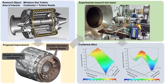
The objective of this study is to present experimental research performed on MGT hot section variable geometry. The variable geometry combustion chamber air holes and variable geometry turbine nozzle impact are discussed. The significance of the research is related to the increase of the efficiency of an MGT and the reduction in its pollutant emission. The novelty of the research is related to the presented variable area of the hot section modules’ impact on thermal efficiency and NOx emissions. The proposed thermal explanation of the variable geometry impact on the MGT global parameters has not been researched in the past, and based on achieved results, allows for the more efficient use of fuel chemical energy in wide operational regimes.
2. Materials and Methods
The research conducted on the proposed variable geometry combustion chamber and turbine section was performed on two research stands: a stationary combustion chamber test stand (test stand no. 1) that allowed simulation of the rotational speed and an MGT test stand (test stand no. 2). Both tests operated at a full regimen, including characteristic rotational speeds: 40,000, 60,000, 80,000, 100,000 and 120,000 rpm. Six cases of primary and dilution zone hole opening were evaluated: 100%, 83%, 59%, 39%, 22% and 14% [
27]. Variable geometry turbine nozzle tests were performed for four previously determined characteristic nozzle twist angles: −4°, 0°, +5° and +7° [
28,
29,
30]. Ambient parameters varied between +17 and +24 °C, an atmospheric pressure of 998 to 1009 hPa and a relative humidity of 38% up to 58%. Details of the test stand, measurement and acquisition system as well as experimental and numerical results can be found in previous articles [
27,
28,
29,
30,
31,
32].
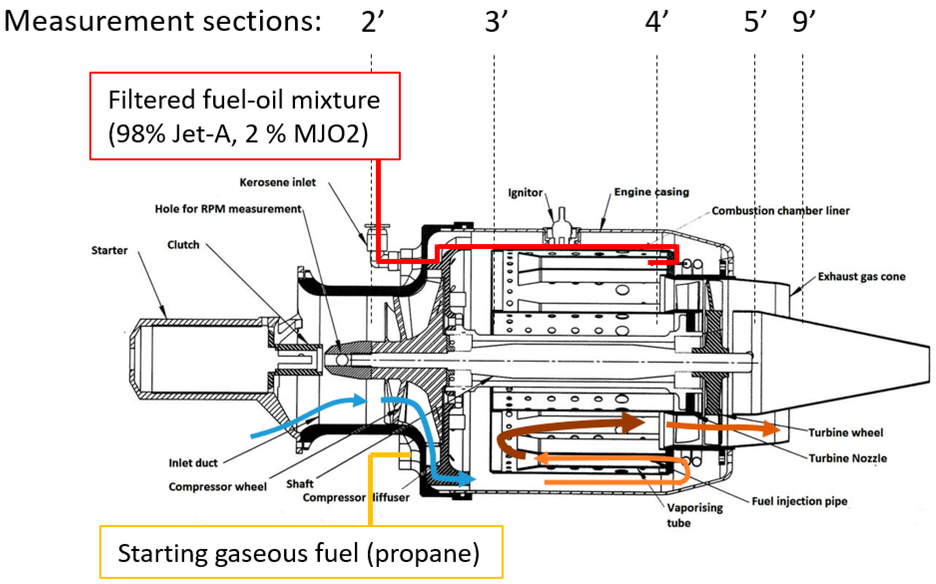
Figure 1 and
Figure 2 show the test stand configurations that were used to carry out the experimental campaign.
The proposed hot section variable geometry consists of two previously researched systems: combustion chamber variable area air holes described in detail in [
27] and the turbine’s variable area nozzle described in [
28,
29].
The first system allows the control of the area of the combustion chamber’s primary and dilution zone holes. The traditional and most robust way to adjust the area of the combustion chamber air holes is to use a unison ring with holes that can rotate around the gas turbine axis and change the holes’ effective area. The proposed design consists of two rotary rings, which can adjust the effective area of the holes allowing the control of the delivery of compressed air to the combustion chamber.
The proposed design of the combustion chamber with variable area air holes, in both primary and dilution zones, was devised, manufactured and evaluated on miniature combustion chamber test stand (test stand no. 1). Detailed results are presented in [
27,
30]. In
Figure 3a, a model of the variable area combustion chamber air holes and respective area of dilution holes is shown. The system was applied to the MGT combustion chamber model and was installed on an experimental test stand allowing for the monitoring and recording of the thrust, emissions, pressures and temperatures. The test stand, measurement techniques and methodology are described in detail in [
31,
32].
Available research on combustion chambers shows potential for combustion process optimization and emission reduction depending on the primary and dilution hole area. The change of air hole area changes the amount of air delivered to primary and dilution zones. The bigger the air hole area, the more air gets to a specific combustion chamber zone, effectively increasing local air to fuel ratio (AFR) and controlling local combustion temperature. Closing primary zone air holes increases the temperature in the primary combustion zone, but also reduces the temperature at the combustion chamber outlet due to additional cooling air redirected to the dilution zone. Similarly, closing the dilution holes increases the combustion chamber exit temperature as less air is added for quenching the hot combustion gases. Both methods allow for adjustment of the turbine inlet temperature (TIT) profile and pattern factors.
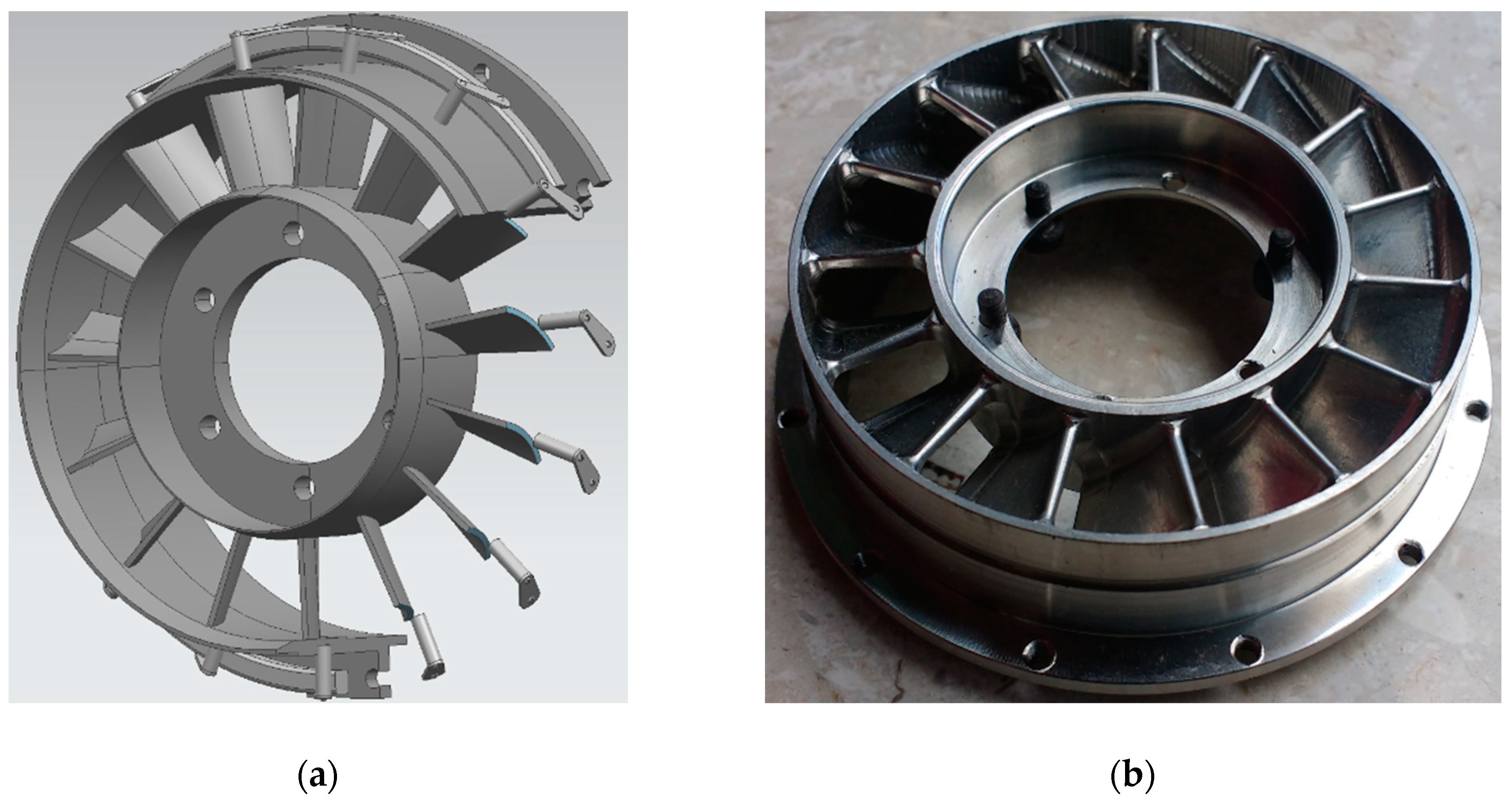
The second system contains adjustable turbine nozzles, whose effective area can be modified by changing the nozzle cascade inclination angle. The standard and the simplest way to adjust the nozzle angle is via lever arms connected with an external unison ring. However, considering the recent rapid development of wing-morphing technologies, one can propose an application to nozzle design. Lever arm technology allows the rotation of the entire airfoil around an axis passing through the aerodynamic center of the airfoil; wing-morphing technology allows for relative rotation of the different sections of an airfoil in such a way that the inclination angle changes spanwise. Such a hypothetical adjustable nozzle built using morphing technology would be able to change the effective area of the turbine without an adverse impact on clearances. One can also consider other ways to implement the variable geometry turbine nozzle system—e.g., by adjusting the rotor blade angle as in the case of water turbine nozzles and by controlling the area of turbine channels as afterburner exhaust nozzles do. The variable area nozzle (VAN) concept was experimentally tested on an MGT test stand (test stand no. 2). Details of the design and research have been previously discussed in [
27,
29]. The articles describe testing the stands’ set ups, methodology and materials used.
Figure 4 shows a 3D model of the variable area nozzle concept and the researched turbine nozzle section that was modified by twisting original nozzles by +5°.
The general idea behind the turbine’s variable area nozzle system is related to mass flow rate and thrust alteration in order to achieve increased efficiency at partial power. Thrust, mass flow, exit velocity exit pressure and turbine nozzle effective area are corelated. Turbine nozzle closure results in effective area reduction that decreases mass flow and thrust. On the other hand, gas turbine efficiency as described in [
26] is expected to rise as the result of increased TIT especially at partial power [
26,
33]. The Equations (1)–(3) describe general efficiency relations for a miniature gas turbine.
where:
Vi—inlet velocity,
Ve—outlet velocity.
From the Equation (1), one can observe that the propulsive efficiency increases with the exit velocity approaching the inlet velocity value. The propulsive efficiency parameter is often taken into consideration while designing gas turbines for aviation applications. It should also be taken into consideration that propulsive efficiency is only a component of the overall efficiency, described by Equation (2).
The thermal efficiency is described as a rate between the useful net work performed by the system and heat added to the system. Considering that the useful network is equal to the difference between heat added to the system and heat losses, the thermal efficiency can be described by Equation (3).
where:
Qin—heat that is added to the cycle and is also used to propel compressor;
Qout—heat loss removed to the ambient atmosphere.
Thermal efficiency is the main measure of efficiency for industrial and marine gas turbines. It generally depends on TIT and can be alternatively described as a function of the compressor pressure ratio. The gas turbine industry has been increasing TIT for decades, and this is due to subsequent thermal efficiency improvement. Every improvement of TIT allows for an increase in the optimum compressor pressure ratio, hence requiring more advanced airfoil and clearance control technologies. Recuperators and regenerators are often employed to further improve thermal efficiency at the cost of slight power decreases, which is the case of industrial gas turbines. It has been experimentally shown in [
29] that the turbine’s variable area nozzle adjustment not only affects mass flow through the gas turbine and consequently the efficiency of the compressor due to the change of the compressor turbine working line but also has an impact on the TIT, effectively changing combustion chamber working parameters. Such system can be used for optimizing maximum heat recovery, especially at gas turbine partial power [
26,
33]. Based on the above considerations, it can be concluded that proposed variable area systems allow for the change of the operating regime of the MGT. This change can be useful in many applications, such as the generation of the working medium with proper thermodynamic parameters to power the low pressure turbine, achieving optimum turbine efficiency for a wide spectrum of working regimes and controlling gas turbine emissions and fuel consumption.
Numerical analyses were carried out in order to interpolate and understand details of the achieved experimental results of both the variable geometry combustor and turbine nozzle. Three-dimensional numerical models of the GTM-120 engine and its components—combustion chamber and turbine—were prepared using methods such as laser scanning. Commercial codes based on ANSYS Fluent (3.6, Ansys, Inc, Canonsburg, PA, USA) were used to simulate combustion process and flow through the turbine. Details of the 3D numerical models are presented in [
27,
29].
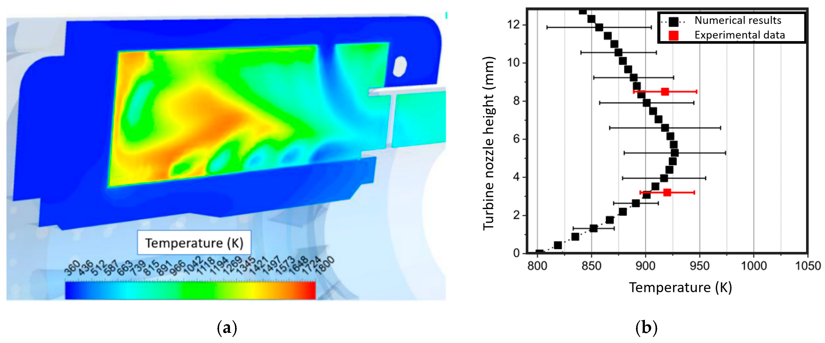
Figure 5 shows numerical and experimental results of TIT measurement and numerical modeling values. The achieved results show significant temperature variation along channel height. This variation impacts the measurement accuracy of TIT and further calculations. The calculated root-mean-square error (RMSE) of numerically and experimentally obtained TIT is equal to approximately 13.5°. Comparable results and conclusions were drawn by Oppong [
6]. For research clarity, the temperature tolerance measurement has been omitted on 3D graphs and presented on the resulting thermal efficiency graph.
3. Results
The results achieved using two different test stands are presented and discussed in this section. The air mass flow and fuel mass flow feeds were researched on test stand no. 2 in nominal configuration. Standard air and fuel mass flow rates at characteristic engine rotational speeds were established and used to feed the combustion chamber in test stand no. 1.
Table 1 and
Figure 6 show TIT measurements for nominal (100% opening) and variable combustion chamber air hole area achieved on test stand no. 1. The experimental measurement results on this and following 3D maps are marked with white bubbles. The achieved results are interpolated using the Renka–Cline algorithm [
34] to cover the whole spectrum of MGT rotational speeds. The TIT varies depending on the combustion chamber air hole area. Experimental research on the variable primary hole area shows the highest TIT measurements for the nominal (100%) opening for all researched rotational speeds (
Figure 6a). On the contrary, dilution hole area reduction allows for TIT increase at all rotational speeds. The highest TIT was achieved with 22% hole opening (
Figure 6b). This result can be attributed to reduced cooling of the exhaust gases from the combustion chamber, which had the highest effect in the case of maximum researched rotational speed.
The variable geometry turbine nozzle section testing was performed on both test stands: test stand no. 1 and test stand no. 2. Results from test stand no. 2 were chosen for the purpose of this study as they include mass flow change impact on engine performance. The test stand no. 2 governor was set to operate the engine at a specific rotational speed. The impact of turbine nozzle angle on TIT and fuel consumption is shown in
Figure 7. The highest TIT was achieved with +5° turbine nozzle closure. Further closure of the turbine nozzle to +7° led to significant mass flow rate decrease and TIT reduction. With +7°, flow through turbine nozzle reached supersonic speed and choked the flow through turbine. This effect can also be observed in the fuel consumption graph. Fuel consumption change follows TIT changes. With the highest TIT, an increase in fuel consumption can also be observed at 120,000 rpm with 0° and +5° nozzle closure.
3.1. Thermal Efficiency Analysis
Analysis of the experimental results obtained during research of the variable geometry systems was performed from the thermal efficiency perspective, which is directly related to TIT. At partial power, a decrease in compressor outlet temperature and hence TIT is the cause for the low performance of the gas turbine [
26,
33]. The researched variable geometry systems allow the control of the combustion chamber’s local and outlet temperatures. The analysis of the gas turbine thermal efficiency related to different variable geometry systems is shown in
Figure 6,
Figure 7 and
Figure 8. The researched thermal efficiency of the gas turbine was calculated for the whole gas turbine system and is defined by the Equations (4)–(6):
where:
cpe—specific heat of the combustion gases;
cpa—specific heat of air;
FAR—fuel to air ratio,
T0—inlet temperature;
T3′—temperature at compressor exit;
T4′—turbine inlet temperature;
T9′—temperature at the exit from gas turbine nozzle.
Thermal efficiency was calculated using results of two test stands described in [
27,
29]. These results cannot be directly used for quantitative thermal efficiency calculation; however, they show qualitative thermal efficiency improvement and direction for further detailed research.
Figure 8 shows the simulated thermal efficiency of the combustion chamber with primary cooling hole variable geometry employed. The results show relatively small improvement only at the lowest simulated rotational speed of 40,000 rpm for 39% and 59% of the cooling hole opening (1.8% and 3.5%, respectively). At rotational speeds of 80,000 and 120,000 rpm, the highest thermal efficiency was obtained for full (100%) primary hole opening.
Results of the dilution hole variable geometry impact on simulated thermal efficiency is shown in
Figure 9. The highest (up to 36%) thermal efficiency increase at high simulated rotational speed of 120,000 rpm was achieved with 22% dilution hole opening. The same dilution hole opening at lower rotational speeds of 40,000 and 80,000 rpm results in low thermal efficiency of 9% and 8%. This result is attributed to an increase in the combustion chamber temperature driven by dilution zone cooling decrease and the simultaneous increase in the primary combustion zone feed. The effect is especially strong when high air pressure is delivered at the highest rotational speed of 120,000 rpm. As discussed, this phenomenon reaches maximum at 22% dilution hole opening below which thermal efficiency decreases, when dilution hole area is further reduced to 14% of original opening. For other rotational speeds and dilution hole openings beyond 22%, only minor thermal efficiency improvement relative to 100% original hole opening can be observed at 80,000 rpm and 59% hole opening (by ca. 5% compared to original holes geometry). The applied Renka–Cline interpolation algorithm resulted in approximated pick close to the experimental measurement. The quantitative value of the visualized pick has not been experimentally confirmed.
The use of variable turbine nozzle geometry results in TIT increase and is applied in the industry—e.g., to maintain constant low-pressure turbine (LPT) entry temperature. This and other effects of the variable turbine nozzle geometry are discussed in [
26]. Its impact on MGT thermal efficiency shown in
Figure 10 indicates that the highest improvement was achieved at 120,000 rpm rotational speed with +7° turbine nozzle closure; however, at this rotational speed and nozzle closure, the MGT operation can become unstable and close to the stall margin. Therefore, the maximum recommended turbine nozzle closure is +5°, with maximum of 32% of thermal efficiency. This thermal efficiency improvement is directly driven by rapid TIT increase related to limited effective nozzle area and increased static parameters inside the combustion chamber. The effect was especially strong at the highest researched rotational speed, but a thermal efficiency of 6% at 80,000 rpm could also be noticed.
Opening the turbine nozzle at the −4° setting had a positive effect on thermal efficiency at low rotational speeds in the range of 40,000–80,000 rpm, while a drop in efficiency could be observed at 120,000 rpm. The improvement in thermal efficiency at 40,000–80,000 rpm is likely related to improvements in turbine flow conditions and combustion quality in the combustion chamber. However, a further increase in the rotational speed caused a significant deterioration of the conditions of flow through the turbine and consequently unstable operation of the gas turbine. During repetitive tests, the rotational speed of 120,000 rpm has not been reached in discussed turbine nozzle open configuration. The presented map is based on experimental result interpolation [
34].
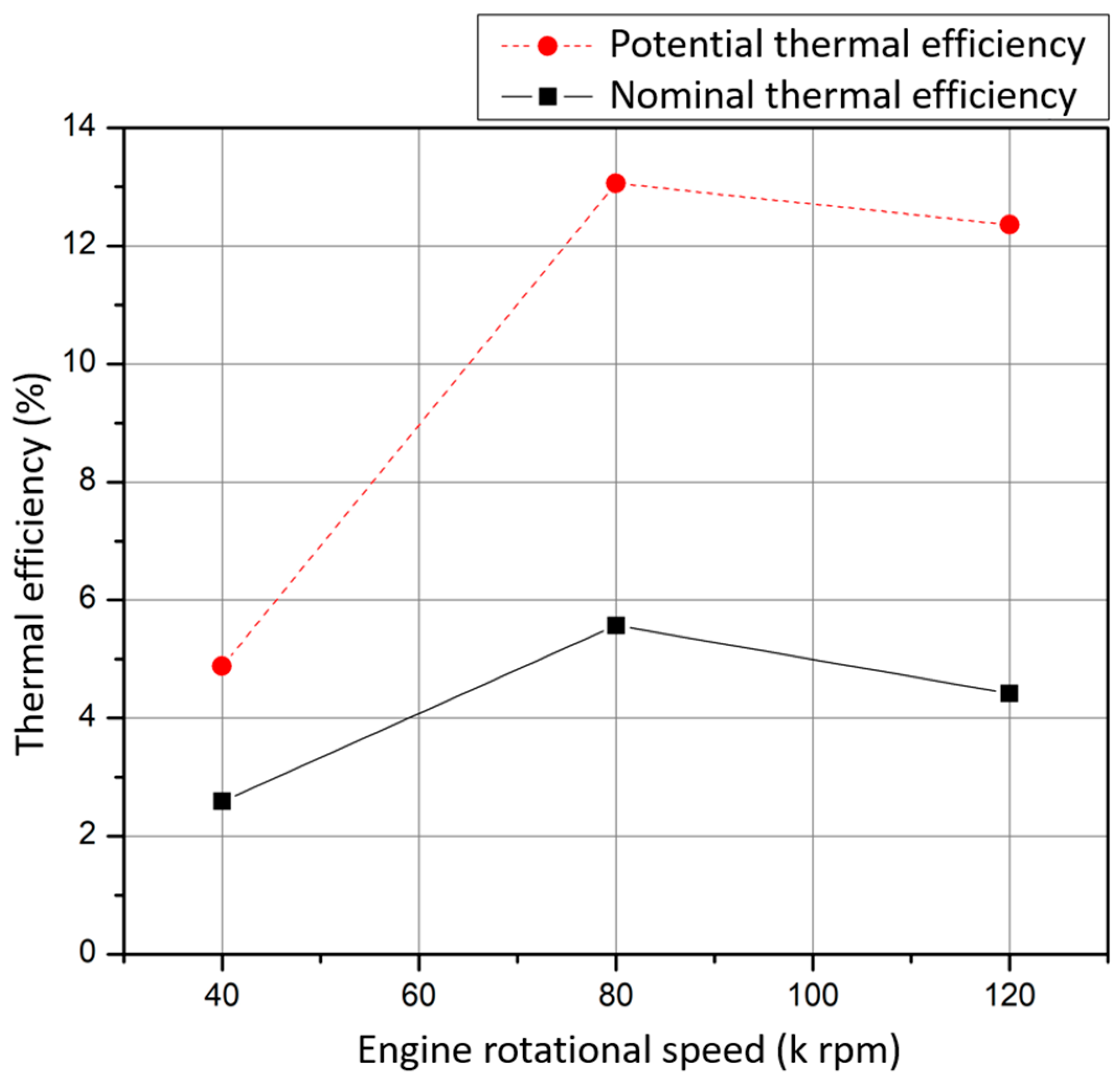
The total impact of the combustion chamber and turbine nozzle variable geometry systems on gas turbine thermal efficiency is presented in
Figure 11. The optimal thermal efficiency is the summary of results of thermal efficiency improvements at different rotational speeds due to variable geometry primary and dilution holes and turbine nozzle variable geometry research. The optimal thermal efficiency result features a significant error related to TIT measurement accuracy and its change in the real engine. Error estimation was performed using thermal efficiency calculations for the highest and lowest temperatures registered in each case.
The real cycle gas turbine efficiency is the product of efficiency of its components: inlet, compressor, combustor, turbine and nozzle. The discussed variable geometry systems have a direct improvement impact on combustor and turbine efficiencies and an indirect impact on other modules due to flow parameter changes. Its impact on gas turbine thermal efficiency can be estimated using the following Equations (7) and (8) assuming constant inlet, compressor and nozzle efficiencies:
The achieved results show that at rotational speed of 40,000 rpm with combustion chamber primary zone holes closed at 59% and the turbine nozzle closed by +5°, the projected thermal efficiency will rise to 5%. At 80,000 rpm, the highest thermal efficiency of 13% was projected with dilution zone holes at 59% opening and turbine nozzle closed by +5°. The highest efficiency gain can be expected at the highest researched rotational speed of 120,000 rpm. With dilution zone holes at 22% opening and turbine nozzles closed by +5°, projected efficiency would rise above 30%. In
Figure 11, the thermal efficiency at 120,000 rpm was reduced to 12.2% by limiting TIT to 1000 K. The limitation was related to turbine parent material durability in the high temperature environment at high rotational speed. The use of the better metal alloy should allow the improvement of turbine durability. The limitation can be skipped in the case of special gas turbine applications (e.g., one time use in aircraft target drone). It can also be overridden by hypothetical turbine cooling or application of a coating layer. The highest value of MGT projected thermal efficiency at 120,000 rpm speed is driven by raised TIT up to 1230 K and rapid temperature drop in the turbine due to improved expansion in the turbine nozzle at a high pressure ratio and locally supersonic nozzle outflow velocity allowing for better rotor flow energy recovery. These benefits result in lower fuel consumption compared to nominal turbine geometry operation. They also lead to compressor operating line shift and a resulting decrease in mass flow rate (by 6%) and specific thrust (by 15%), as shown in [
27]. The operating line of the compressor is also shifted, and hence, engine operation becomes sensitive to flow separation and can be subjected to compressor stall or surge. A literature review confirms that the margin of stable compressor operation is at the 0.1–0.2 level [
35] and, therefore, can be affected by the proposed variable geometry system.
3.2. Emissions Analysis
The impact of the nozzle geometry on the emissions of pollutants and oxygen concentration in exhaust gases is the result of change of the combustion chamber parameters. Experimental analysis of the NO and NO
2 emissions showed correlation between combustion chamber cooling hole diameter and NO
X production [
27,
30].
Primary combustor chamber cooling hole geometry impacts combustion temperature in the forward part of the chamber. Its effect on NO emissions is consistent with extended Zeldovich’s thermal NO production mechanism [
36], based on which the NO
x formation depends exponentially on temperature. Primary combustor chamber cooling holes allow for an increased amount of air to be delivered to the primary combustion zone. A smaller portion of air is directed towards the dilution zone decreasing the NO to NO
2 transformation rate. The effects of lower NO and NO
2 emissions at 100% primary zone combustion chamber hole opening are visible in
Figure 12a,c.
Decreased temperature in the dilution zone of the combustion chamber is a result of dilution zone air hole effective area increase. The excess of air reduces dilution zone temperature and accelerates the reactions with negative activation energy (nitrogen monoxide oxidation to nitrogen dioxide transformation reaction) and simultaneously decreases the amount of air delivered to the primary combustion zone. Therefore, opening of the dilution holes increases the emissions of NO, as a result of locally decreased AFR in the primary combustion zone and increases the emissions of NO
2, as shown in [
27]. On the contrary, closure of the dilution holes decreases the emissions of NO
2 by up 82% at 120,000 rpm. Both phenomena are presented in
Figure 12b,d, respectively.
The impact of variable turbine nozzle geometry on NO and NO
2 emissions has been studied and briefly discussed in [
27]. The impact of nozzle geometry on nitrogen oxides emissions is connected to its direct impact on the effective combustion chamber outflow area, which affects both combustion temperature and gas turbine fuel consumption, as shown in
Figure 13c,d, respectively. Closure of the nozzles increases the combustion chamber static temperature and pressure which accelerate NO creation reactions per thermal NO production mechanism [
27]. Similarly, closure of the nozzles decelerates the flow through the combustion chamber, effectively extending combustible gas residence time in the hot combustion zone. The effect of residence time reduction in a combustion chamber has been discussed in [
6] as a cause for increased viscous losses due to increased entropy change. In [
29], the authors showed plots of Mach number and static pressure for nominal and +5° closed turbine nozzle. The Mach number in front of the turbine nozzle decreased with nozzle closure, while static pressure increased.
As a result, significant changes in NO emission can be observed in
Figure 13a: at 40,000 rpm, an increase can be noted both when opening the nozzles by −4° (49% increase) and when closing the nozzles by +5° (58% increase) and then by +7° (51% increase). NO emission increase at turbine nozzle opening (−4°) is likely to be related to a relatively high combustion temperature (
Figure 13c), which accelerates NO production per thermal production mechanism.
At 80,000 rpm, NO emission significantly decreased at +5° nozzle closure (49% decrease) and the trend continued when nozzles were shuttered by +7° (78% NO emission decrease related to original configuration). Registered high NO emission decrease at +7° nozzle closure is the result of both reduced fuel consumption and TIT. With +7° nozzle closure fuel consumption decreased by 33% and temperature by 21%. The NO emission decrease at turbine nozzle closure is the result of thermal efficiency increase shown in
Figure 10, reduced fuel consumption and decreased combustion temperature. This comparison proves that increased combustion temperature has a direct impact on increased NO emissions.
At 120,000 rpm, the NO emission decreased when closing the nozzles by +5° by 31% compared to nominal geometry increase. The emissions at −4° nozzle opening and +7° closure have not been registered. Registered NO emission decrease at +5° nozzle closure reflected the rising impact of thermal efficiency improvement and hence performance improvement of the entire gas turbine, overwhelming the impact of the thermal NO production mechanism. Temperatures registered during experimental research reached a maximum of 1177 K at nozzles closed by +5°, while in nominal configuration with baseline nozzle geometry, the temperature was kept under the 993 K level (184 K increase).
Turbine nozzle closure by +7° at low power mode at 40,000 rpm resulted in 47% fuel consumption reduction (
Figure 13d). This result confirms the highest overall performance improvement at partial load and is supported by available research [
26].
Increased combustion temperature resulted in NO to NO
2 transformation rate decrease. This explains the decrease in NO
2 emission at turbine nozzle configuration closed by +5° and by +7° and increase in the NO
2 production with −4° nozzle opening visible in
Figure 13b.
4. Discussion
The results presented in this article show that the discussed hot section variable geometry systems significantly impact the thermal efficiency and emissions of the miniature gas turbine. The presented experimental research shows the improvement in thermal efficiency at all operational speeds, reduction in NO and NO
2 emissions and fuel consumption. The achieved results are consistent with other research on nitrogen oxides emissions [
37] showing temperature–NO
x emission proportionality and inverse proportionality with oxygen content [
27]. A review of existing solutions and applications connected with the increasing need for reliable alternative and emergency power supply sources support the need for further research on the miniature gas turbines and hot section variable geometry systems.
The research stands allowed for TIT and exit nozzle temperature measurements. These measurements are, however, prone to the significant TIT profile fluctuations due to the miniature size of the research channel. The average TIT profile is shown in
Figure 5. This challenge was solved using the standard temperature measurement location and multiple repeated tests. As a result, the average values were established for each research point.
It should be noted that the turbine variable area nozzle allows not only to improve the thermal efficiency but also to regulate the thrust of an MGT [
27]. For example, reducing thrust is not desirable when operating with a heavy load, but can be very beneficial when operating at a partial load, which was also mentioned in [
24]. The variable nozzle area effect on engine thrust, SFC and mass flow rate has been shown in
Figure 14. The SFC decreases for a wide range of engine operating points, characterized by thrust, with turbine nozzle closure (
Figure 14a). The highest decrease was observed at low thrust. Turbine nozzle closure also affects turbine operating line reducing mass flowrate and choking the flow at lower mass flow values (
Figure 14b).
The major results of the presented research demonstrate variable geometry combustor air hole impact on TIT and NO
x emissions. For primary zone air holes, a relatively small improvement at a rotational speed of 40,000 rpm has been shown with 39% and 59% of the cooling hole opening (1.8% and 3.5%, respectively). At rotational speeds of 80,000 and 120,000 rpm, the highest thermal efficiency was obtained for full (100%) primary hole opening. The research on variable area dilution holes revealed high TIT increase with air hole area reduced to 22%. The resulting TIT increase rises simulated thermal efficiency to 35%. By using variable geometry of the turbine nozzle, it is possible to influence the mass flow rate and thrust as shown in
Figure 14. Favorable changes in TIT and SFC contribute to an increase in thermal efficiency up to 35%. Results of the undertaken task to assess overall gas turbine efficiency with variable area nozzle are shown in
Figure 14a. SFC reduction can be achieved for low thrust operation. At high power, performance gain is relatively small.
Analysis of the NOx emission as result of variable geometry testing displays emission reduction as a result of primary air hole opening and dilution hole closure. The variable nozzle turbine presents reduced NOx emissions, consistent with nozzle closure and reduced power, at high temperature operation.
The practical impact of the achieved results has importance mainly for overall MGT operation efficiency. The impact of variable geometry combustor chamber air holes allows for better flow management and thus temperature distribution. Achieved TIT increase results in a rise in the thermal efficiency of the MGT. The variable geometry turbine impact is significant at part-power operation. Effective turbine nozzle area decrease results in mass flow rate reduction through the engine as shown in
Figure 14b. It is accompanied with TIT increase resulting in an improvement in thermal efficiency. Further experimental analysis considering compressor bleed may allow mass flow limitation due to nozzle closure to be overcome.
Nonetheless, the complex design of the proposed variable geometry system results in gas turbine structural mass increase and main flow leakages, further decreasing engine efficiency and increasing SFC [
26,
38]. Therefore, further research on specific variable geometry system solutions is needed.
4.1. Research Assumptions and Limitations
The research assumptions are related mainly to test stands configurations, measurement precision and accuracy of the locally manufactured gas turbine elements. The stationary combustion chamber test stand (test stand no. 1) allowed only for the simulation of the rotational speed without the impact of the compressor-turbine rotor. The MGT test stand (test stand no. 2) was equipped with a modified geometry turbine nozzle that did not include tip and platform clearances characteristic for variable geometry airfoils. The precision of temperature measurements, although optimized using standard measurement locations and multiple repeated tests, is prone to combustion chamber outlet temperature profile variation (150 K or 16% variation radially). The custom designed combustion chamber unison rings and turbine nozzles were manufactured to the highest quality but may slightly differ from their digital models due to complex shapes that were not inspected with e.g., CMM equipment.
4.2. Future Work
Future research should include the need for better understanding of phenomena responsible for TIT and NOx emissions changes due to the proposed use of variable geometry hot section systems. The detailed design of proposed variable geometry nozzle system and following CFD modeling of the flow around the variable turbine nozzle will allow a better understanding of the clearances impact on losses. Further detailed CFD modeling showing the variable geometry impact on combustion chamber mixing and chemistry is also needed to quantify chemical reaction changes inside a combustion chamber. The miniature nature of the MGT, high losses related to viscosity and heat fluxes together with low Reynolds number flows constitute a unique and challenging research environment.
A further potential research area from the MGT variable geometry implementation perspective is fuel–water emulsion application. The non-homogeneous fuel mixture with water droplets and surfactant additions decreases the combustion temperature due to its higher heat absorption capability. It also has a potentially beneficial impact on fuel emulsion spray and mixing with air inside the combustion chamber as overheated water droplets eventually disintegrate by micro-explosions effectively scattering fuel emulsion inside the combustion chamber. Initial research on fuel–water emulsion application in MGT revealed the potential for up to 27% NO emission reduction [
39]. Variable geometry may allow the adjustment of MGT operation to specific fuel operation.
Additionally, alternative clean fuels such as hydrogen are considered to supply MGT [
40]. Low mass, compact design and high reliability compensate for the current complexity of existing hydrogen production, storage and supply systems. In order to guarantee low nitrogen oxide emission, hydrogen combustion requires a high air-to-fuel ratio, which can be easily guaranteed by a miniature gas turbine. Potential applications are wide: gas turbine-based power systems, alternative for reciprocating engines and supersonic vehicles. Micro-turbine-based power systems are developed by Capstone and other companies for distributed generation needs. Reciprocating engines cannot be easily modified for hydrogen combustion due to limited piston volume and need for air compression. MGT advantage is a surplus of compressed air, and there is no need to rescale the entire engine for hydrogen use. Hydrogen supply requires noble metal application to eliminate the adverse hydrogen embrittlement effect on gas turbine components. The research on efficient high speed propulsion in air turbo-rocket hydrogen-fueled configuration was studied in the frame of the EU funded program LAPCAT II and presented in [
41]. The research considered variable cycle turbofan engine combined with an air turbo-rocket cycle (ATR) so that high efficiency was obtained during the acceleration phase. For such an application, already featuring multiple variable geometry systems, a variable geometry turbine nozzle system may be needed in order to maintain the combustor chamber appropriate wall temperature within the thermal capability of the material applied. Additionally, studies on distributed hydrogen propulsion show promising efficiency improvement, based on an aircraft study example [
42]. Such applications may easily incorporate an MGT fed with hydrogen. Another interesting idea is to feed an MGT with a hydrogen blend. Multiple studies exist on diesel-hydrogen blend combustion [
43], though further research on such MGT supply is needed.
5. Conclusions
The conducted research shows that the use of variable geometry in the hot section of the gas turbine (combustion chamber and turbine) allows for a significant improvement in thermal efficiency and specific fuel consumption, as well as for reducing the emission of harmful substances, especially NOx. The achieved results are attributed to combustion chamber local and outlet temperature changes, mass flow alteration and flow path reorganization.
The novelty of the research and achieved results consists of thermal efficiency analysis of the variable geometry combustor and turbine. Proposed variable geometry systems allow for non-traditional improvement of the MGT efficiency. Moreover, thermal explanation has been proposed to elucidate NOx emission reduction in and changes of the global MGT parameters.
Research performed at the Warsaw University of Technology demonstrated a significant decrease in fuel consumption (up to 47% reduction) at assumed engine rotating speed. Such a phenomenon was achieved thanks to modified turbine nozzle geometry, corresponding TIT increase and thrust decrease. It allowed the improvement in the thermal efficiency of the MGT at partial power. Together with TIT increase and thermal efficiency improvement, nitrogen oxide emission reduction was achieved. Nitrogen monoxide emission decreased by a maximum of 78% compared to nominal values at 80,000 rpm and +7° turbine nozzle closure. Combustion chamber dilution hole variable geometry system research resulted in nitrogen dioxide emission reduction by maximum 82% at simulated 120 rpm turbine speed.
Mutual adjustment of the combustion chamber and turbine operating parameters creates an additional opportunity to improve the operating conditions of the gas turbine unit in a wide range of rotational speed changes. Thanks to this, by using an appropriately selected control system, operating on the basis of maps determining mutual favorable operating points, it is possible to obtain an improvement in efficiency and reduction in emissions for various rotational speeds and loads. The use of variable geometry in relation to the design of the hot part of the gas turbine seems to be particularly attractive in relation to small gas turbines characterized by relatively low efficiency and high emission of pollutants.


