Abstract
A two-dimensional axisymmetric thermal-fluid-solid coupled mathematical model of a contact mechanical seal is established. The finite difference method is used to solve the control equations for the fluid pressure and temperature of the seal end face, and the finite element method is used to determine the thermal deformation state of the seal. The seal’s performance at different working speeds was studied and verified by experiments. The results show that under the combined actions of thermal and mechanical deformations, the seal end face forms a convergent leakage gap from the outer diameter to the inner diameter. The minimum film thickness is observed on the inner diameter side of the seal end face, and the highest end face temperature coincides with this location. With increasing working speed, the contact force at the inner diameter side increases, the temperature difference between the inner diameter and the outer diameter of the end face increases, and the leakage rate correspondingly increases. The numerical simulation results are in good agreement with the experimental results. The model and calculation method can be applied to other forms of mechanical seal design and optimization.
1. Introduction
A mechanical seal is an axial end face device, and the fluid pressure and elastic force (or magnetic force) of the compensation mechanism keep the end faces of the rotor and stator in contact and allow sliding to prevent fluid leakage; thus, such seals are called end face seals [1,2]. With the development of industrial technology, mechanical seals have been widely used in the petrochemical industry, engineering machinery, the automobile industry, deep sea operations, aerospace, and other fields [3]. Mechanical seals are among the most critical components in these devices. Seal performance directly affects the normal operation of devices and can seriously endanger the safety of operators and passengers. For example, the 1986 explosion of the National Challenger was caused by fuel leakage due to the failure of a seal ring [4]. The explosion led to the disintegration of the space shuttle, killing seven crew members. In 2004, the mechanical seal of the compressor on the synthetic ammonia production equipment at Jilin Chemical Industry Company Chemical Fertilizer Plant was excessively worn, resulting in the failure of the seal ring [5].
In recent years, scholars from all walks of life have performed research on mechanical seals and achieved various results. Blasiak et al. [6] established a numerical simulation model of a noncontact mechanical seal considering the thermal deformation of the seal end face and the heat transfer of the film between seal faces. The results showed that thermal deformation cannot be ignored when designing mechanical seal structures under high operating conditions. Migout et al. [7] studied the vaporization evolution trend of film on a seal end face considering face deformation. Notably, a large temperature gradient can adversely affect the stability of the film at the seal face. Zhu et al. [8] established a numerical model of multifield thermodynamic coupling. The correctness of the model was verified by experimental research, and the model was developed into software convenient for application. Galenne et al. [9] established a two-dimensional thermoelastic flow model, considered the coupling relationship between fluid dynamics and the thermoelastic deformation of the structure through the influence matrix, and analyzed the stress form of the seal structure. Brunetiere et al. [10,11] established a three-dimensional thermoelastic-hydrodynamic numerical model to analyze seal performance under steady-state conditions. The results showed that if the influence of thermal deformation is not considered in the analysis process, the simulation results have large errors. Chen Huilong et al. [12] established a three-dimensional geometric model of a mechanical seal with CAD software and performed a multifield coupling simulation analysis with the Ansys Workbench. The results showed that the maximum deformation and stress of the seal ring were obviously affected by the medium pressure, and the working speed had little effect on these variables. Zhou Min et al. [13] performed simulation analyses of three-dimensional flow field dynamics based on a self-pumped groove mechanical seal in Fluent software and determined the effects of relevant geometric structure parameters on seal performance. Peng Xudong et al. [14] established a two-dimensional axisymmetric model of a mechanical seal with MSC Marc finite element software. The Reynolds equation and energy equation were solved by the finite difference method. The results showed that an increase in the pretightening force increases the opening force and leakage rate. Yang Dandan et al. [15] established periodic models of rotors and stators using finite element software and performed three-dimensional force coupling and force-heat coupling calculations. The results showed that the seal face will form a circumferential wave degree deformation and convergently taper. Most of the above-mentioned researchers simplified the coupling effect between the seal ring and the oil film without considering the change in the radial curvature of the seal. Moreover, weak coupling is generally adopted in multifield coupling research, which leads to prediction errors for the seal face deformation characteristics and seal performance.
In this paper, the author established an axisymmetric multifield coupling model for mechanical seals by considering the relationship between mechanical deformation and thermal deformation, the pressure field distribution of the lubricating film, and the viscosity–temperature characteristics of the liquid film. The finite difference method combined with a numerical iteration technique was used to obtain the numerical solution of the theoretical model. The influence of the working speed on seal performance was analyzed, and an experimental study was conducted.
2. Theoretical Model
2.1. Geometric Model
The mechanical seal structure for an aviation pump was studied. The specific structure is shown in Figure 1; the rotor is fixedly connected to the rotating shaft and rotates with the rotating shaft, while the stator is a floating ring. There are 18 coil springs as compensation springs on the back of the stator seat. To improve the calculation efficiency and shorten the calculation time, some simplifications were made, as the rotor and stator of the mechanical seal are axisymmetric structures, we can simplify them into a geometric model of the longitudinal section. The inner side of the seal ring is at atmospheric pressure Pi, and the outer side of the seal ring is at the medium pressure Po. It is simpler and clearer to express the structure dimension drawing separately from the simulated boundary conditions. See Figure 2 for the simulated boundary conditions.
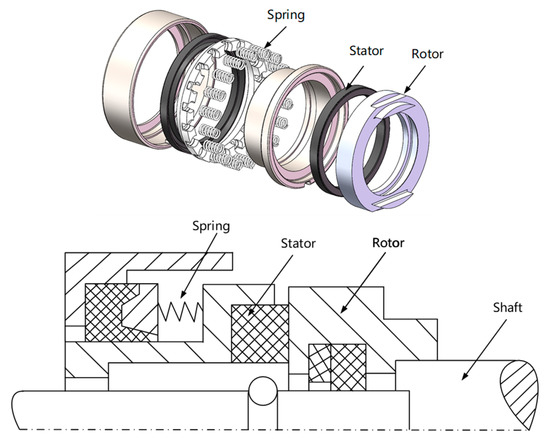
Figure 1.
Schematic diagram of the mechanical seal structure.
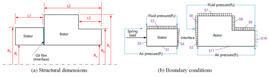
Figure 2.
Mechanical seal simulation model.
2.2. Mathematical Model
2.2.1. Fluid Domain Governing Equations
To avoid losing generality, it is assumed that the sealing medium is a Newtonian fluid, and the effect of the volume force is ignored. The fluid does not slip at the interface. Regardless of pressure changes in the film thickness direction, the fluid flow is laminar. According to the above assumptions and the characteristics of the geometric model, the Reynolds equation [16] of the film pressure distribution in cylindrical coordinates can be obtained through the Navier–Stokes equation and the continuity equation, as shown in Formula (1).
where ρ is the liquid density, h is the film thickness between the seal end faces, p is the film pressure, t is time, ω is the angular velocity of rotation, r and θ are column coordinate variables, and μ is the film viscosity.
The steady-state Reynolds equation expressed in the polar coordinates is given by
In the current research, there are several commonly used viscosity–temperature relations. Because it is convenient in numerical calculations, the fluid film viscosity–temperature equation for Reynolds lubrication [17] was adopted, as shown in Equation (3).
In the formula, μ0 is the reference viscosity, T0 is the reference temperature, β is the viscosity–temperature coefficient, and T is the film temperature at the end face.
2.2.2. Energy Equation
For a lubricating liquid film, the heat generated by viscous shearing is dissipated by heat conduction and convection to the surroundings, and a stable temperature field is formed; this field is influenced by the energy equation and its boundary conditions. Without considering the effects of the volume force and thermal radiation, an energy equation [16] suitable for this model can be obtained, as shown in Equation (4).
where ρ is the liquid density, cv is the specific heat of the film, T is the seal ring temperature, Vr is the radial velocity, Vθ is the circumferential velocity, Vz is the axial velocity, k is the thermal conductivity coefficient, and μ is the liquid viscosity. The detailed expressions of Vr and Vθ are shown below.
2.2.3. Heat Flux Equation
The temperature rise of the sealing ring comes from the frictional heat flow q of the end face, including the viscous shear heat flow of the liquid film qf and the frictional heat flow of the end face contact qc. Where qf is calculated as follows:
where ω is the angular speed of the stator, h is the film thickness, and μ is the film dynamic viscosity, expressed by the viscosity–temperature equation of Formula (3).
The frictional heat flow of the sealing end contact qc is determined by the following formula:
In the formula, f is the dry friction coefficient of the sealing end face, and pc is the contact pressure of the sealing end face.
2.2.4. Contact Pressure Equation
Using the plastic contact model and assuming that the height of the convex body is Gaussian normal distribution [18], the contact pressure pc can be determined by the following formula:
where H is the yield strength of the seal ring material, and Ra is the standard deviation of the roughness of the face.
2.2.5. Heat Conduction Equation
The heat of the rotor and the stator comes mainly from the friction heat between the seal faces. To simplify the complexity of the heat distribution, a global method is used to solve for the temperature field distribution. The rotor and stator are modeled as one component, and the heat generated between the end faces is taken as the internal heat source. Based on numerical heat transfer, the temperature control formula [19] for the seal ring is shown in Equation (9):
where T is the temperature distribution in the seal ring, r and θ are column coordinate variables, zi is the axial coordinate of the seal ring, and i = 1 and 2 represent the rotor and the stator, respectively.
2.2.6. Solid Deformation Equation
Considering the regular shape of the mechanical seal we studied and the absence of dynamic pressure grooves on the end face, the deformation of the seal end face was considered consistent in the circumferential direction. Therefore, a two-dimensional axisymmetric model was used to replace the three-dimensional model and calculate deformation; this approach reduced computational resource use and improved computational efficiency. The weak integral form of the thermoelastic deformation formula for a seal ring is derived by using the principle of virtual displacement [20]:
where {ε} is the strain component; [D] is an elastic matrix; {u} is a displacement array; and {P} is the face force load array, which encompasses the contact force, medium pressure, atmospheric pressure, and spring force. {ε0} is the strain component associated with the temperature increase of the seal ring. For axially symmetric mechanical seals , α is the thermal expansion coefficient of the material.
2.3. Boundary Conditions
- (1)
- Pressure boundary conditions. The film on the seal end face serves to isolate the high- and low-pressure chambers. The outer diameter is in contact with the sealing medium in the seal chamber, and the inner diameter is in contact with the atmosphere [16]. Therefore, if the pressure at the inner diameter of the oil film is Pi and the pressure at the outer diameter is Po, then the forced boundary condition adopted is that given in Equation (11). Periodic boundary conditions are also adopted (12).
- (2)
- Temperature boundary conditions. The boundary condition in [11] was also adopted in this study. Figure 2b shows the temperature boundary; at S4 and S5, a continuous boundary condition for heat flow is adopted. The expression of S4 is Formula (13), and that of S5 is Formula (14); at S3, S6, S7, S8, and S9, a thermal convection boundary condition is adopted; and the remaining boundaries S1, S2, S10, and S11 are considered adiabatic.
where ki is the thermal conductivity of the seal ring, and i = 1, 2. Hj is the heat convection heat transfer coefficient.
- (3)
- Force and displacement boundary conditions. As shown in Figure 2b, at contact boundaries S1 and S11, axial slip constraint boundaries are established; S2 is an elastic support boundary; S3, S6, S7, S8, and S9 are uniform pressure boundaries; and S10 is a fixed-constraint boundary. The pressure at seal end face boundaries S4 and S5 is the fluid film pressure calculated from the control Equation (2).
2.4. Sealing Performance Parameters
The main parameters used to measure the seal’s performance are the opening force, leakage rate, and friction torque.
The formula for calculating the opening force is given in Equation (16):
The formula for the leakage rate is given in Equation (17):
The friction torque formula is given in Equation (18):
3. Calculation Process
All the above control equations are solved using the finite difference method combined with multiple iterative numerical algorithms. The computational procedure is shown in Figure 3. This procedure includes three iterations. The first cycle is the iteration of the oil film pressure field at the end face, the second cycle is the force balance cycle, and the third cycle is the cycle of thermoelastic deformation at the end face. There are two ways to judge whether the iterative process converges: the absolute convergence criterion and the relative convergence criterion. The relative convergence criterion is chosen in this paper. As long as the load of two iterations meets the relative accuracy, the iteration is considered to converge, which is defined as follows:
where X stands for pressure and temperature, respectively, ε is the relative accuracy, which is usually 0.01 ~ 10−6 according to the convergence difficulty of the problem. In this paper, taking into account the requirement of calculation accuracy and calculation time cost, it was set as 10−3. When the program reaches iterative accuracy, the seal performance parameter can be derived.
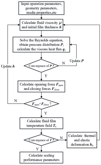
Figure 3.
Computational procedure.
4. Calculation Examples and Results
4.1. Calculation Parameters
A multifield coupling mathematical model that considers the thermodynamic coupling between the solid domain and the fluid domain was established. The governing equations, such as the Reynolds equation, energy equation, and heat conduction equation, were solved by the finite difference method. The parameters of the sealing medium, geometric parameters of the seal rings, and material properties used in the calculation are shown in Table 1, Table 2 and Table 3, respectively.

Table 1.
Properties of the sealing medium.
Table 2.
Geometric parameters of the seal rings.
Table 3.
Material properties of seal rings.
4.2. Analysis of Results
Figure 4 shows the change in heat generation power with the rotation speed. The heat generation power increased approximately linearly with increasing working rotation speed. Figure 5 shows the end face temperature distribution along the radius at different rotational speeds. As the rotating speed increased, the temperature increased gradually because the increase in rotating speed leads to increases in the viscous shear heat and contact friction heat in the seal gap. The temperature difference between the inner and outer diameters increased gradually due to the contact friction of the microprojections at the inner diameter and the strong convection heat exchange at the outer diameter.
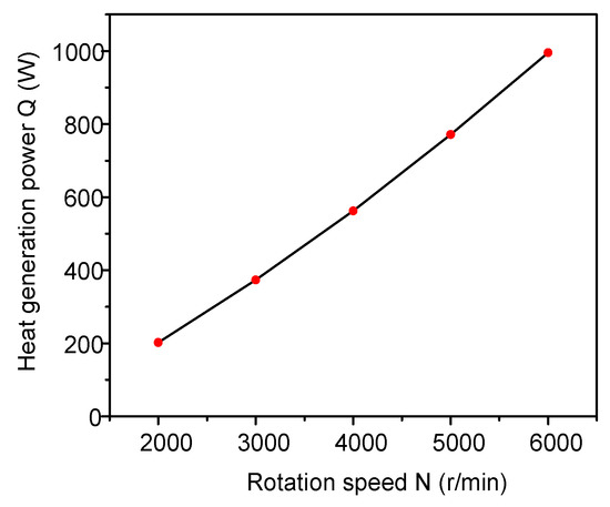
Figure 4.
Variation in heat generation power with rotation speed.
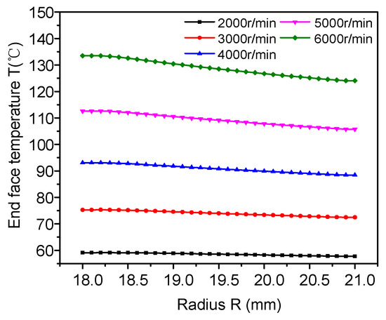
Figure 5.
End face temperature distribution over the end face radius at different rotation speeds.
Figure 6 shows the change in film thickness in the radius direction at different rotational speeds. The gap between seal rings was convergent at different rotating speeds, and the convergence degree gradually increased with increasing rotating speed. The main reason for this trend is that the temperature difference between the inner and outer diameters gradually increased, which caused the thermal deformation at the inner diameter location to gradually increase and eventually caused the convergence degree of the seal gap to gradually increase. Therefore, there is a positive correlation between the change in the end face temperature and the change in the seal gap convergence degree at different rotating speeds: the higher the end face temperature is and the greater the end face temperature difference between the inner and outer diameters is, the stronger the seal gap convergence degree.
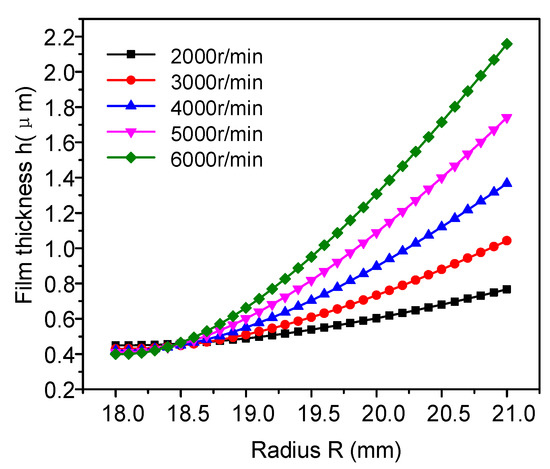
Figure 6.
Variation in film thickness in the radius direction at different rotation speeds.
Figure 7a,b shows the film pressure distribution and the contact pressure distribution in the radial direction of the seal end face at different working speeds, respectively. As shown in Figure 7a, the film pressure distribution at different working speeds exhibited approximately the same quadratic curve. With increasing rotating speed, the wedge shape of the film thickness became increasingly obvious, and the oil film pressure gradually increased in the radial direction, with the amplitude increasing first and then decreasing, reflecting a convex distribution. The greater the increase in the rotating speed is, the more obvious the convex shape becomes. Figure 7b shows that the higher the working speed is, the more uneven the contact pressure near the inner diameter and the greater the maximum contact pressure. The decrease in the minimum film thickness caused the local contact pressure to increase rapidly. An excessive contact pressure may cause severe local wear at the seal end face, resulting in excessive leakage and failure. These issues will be addressed in subsequent experimental studies.
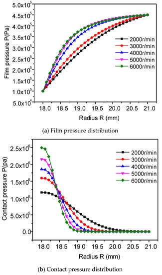
Figure 7.
Film pressure and contact pressure distribution in the radius direction at different rotation speeds.
Figure 8 shows the variation in the composition of the opening force with the rotation speed. Notably, with increasing rotational speed, the proportion of the contact force to the opening force gradually decreased, and the proportion of the film force to the opening force increased. Specifically, the oil film thickness increased, and a convergent gap formed as the rotational speed increased.
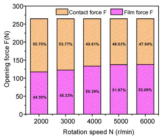
Figure 8.
Proportion of the opening force.
Figure 9 shows the variation in the friction torque with the operating speed. The friction torque first decreased rapidly and then increased slowly with the working speed. Notably, as the rotating speed increased, a lubricating oil film gradually formed at the seal end face, thus reducing the friction torque. When the rotating speed was further increased, the end face forms became convergent, and thermal deformation and force deformation occurred. The inner diameter of the seal ring was in contact with the face, so the friction torque increased. For the mechanical seal structure studied in this paper, the torque was minimum at 4500 rpm.
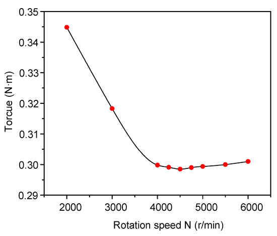
Figure 9.
Torque at different rotation speeds.
Figure 10 shows the variation in the leakage rate with the operating speed. As the working speed increased, the leakage rate also increased. However, from the perspective of the whole change process, the change in the early stage was slow, and a sharp change occurred in the late stage.
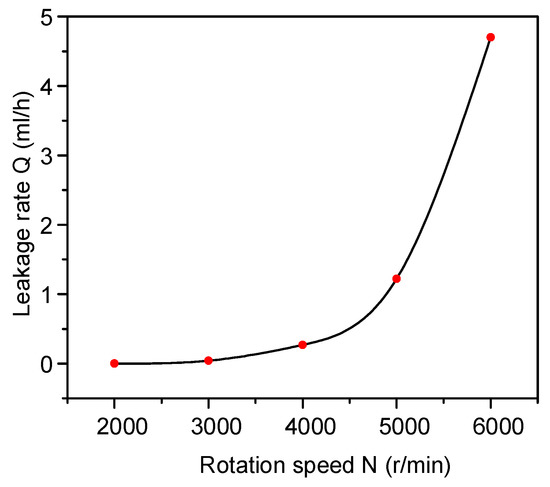
Figure 10.
Variation in the leakage rate with rotation speed.
5. Experimental Research
In this paper, a self-developed multifaceted mechanical seal system was used, as shown in Figure 11. The test rig included the following parts: (1) a servo motor (HSML-954C, 0–10,000 r/min, IP67), (2) a transmission shaft, (3) a torque meter (DR2212, 0–10 Nm, precision: 0.05%), (4) an oil inlet pipe, (5) an oil outlet pipe, (6) a test chamber, (7) a measurement cup, (8) a temperature sensor (MBT5250, −10–150 °C, precision: 0.5%), and (9) a pressure sensor (M20X1.5, 0–6 MPa, precision: ±0.5%). After the stage experiment was completed, the amount of oil in the measuring cup was measured with a high-precision pipette (precision of 0.001 mL), and this amount is the experimental leakage.
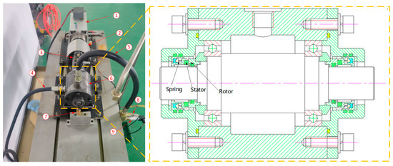
Figure 11.
Mechanical seal test rig.
During the test, the medium temperature in the sealed cavity was 40 °C, and the medium pressure was 0.45 MPa. The spindle speed was controlled at 2000, 3000, 4000, 5000, and 6000 r/min, and the running time of each test speed was 30 min. To reduce the error, each test speed was averaged over three tests.
Among the many parameters that reflect mechanical seal performance, we selected torque and leakage rate as two key parameters for experimental verification and comparison. Figure 12 shows a comparison between the simulation results and the test results for friction torque. The trend of the test values was consistent with that of the simulated values, with the maximum error within 5%. The variations in data are due to small errors associated with the assembly of the test rig and the slight vibration of parts during the test. Figure 13 is a comparison of leakage rates. From the figure, the experimental and simulated values displayed excellent consistency, and the maximum error was within 5%. From the above results, we can conclude that the numerical simulation model established in this paper is accurate and reliable. This method can be applied to mechanical seals in other types of structures.
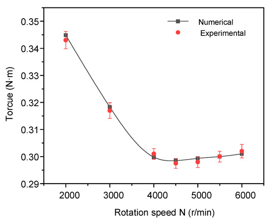
Figure 12.
Variation in the friction torque with rotation speed.
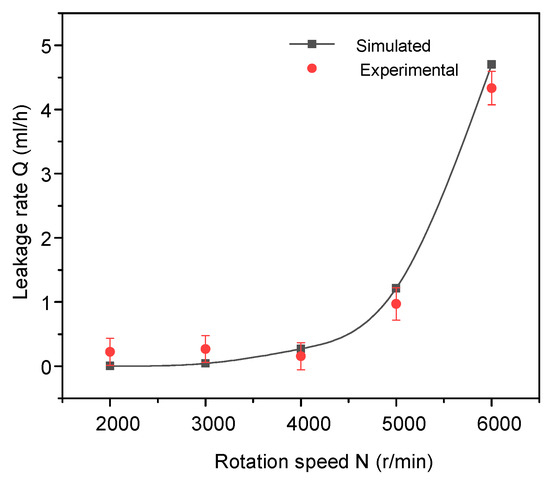
Figure 13.
Leakage rate variations with rotation speed.
6. Conclusions
The main conclusions obtained in this paper are as follows:
- (1)
- The film thickness distribution between the seal interfaces suggests that the comprehensive deformation of the seal end face was not linearly distributed in the radial direction. Therefore, the multifield coupled mathematical model established in this paper effectively reflects the actual situation, thus providing a valuable technical reference for the design of mechanical seals in the future.
- (2)
- With increasing working speed, the heat generation power, end face temperature, maximum contact pressure, and leakage rate increased. The minimum film thickness at the end face decreased, and the friction torque decreased initially and then increased.
- (3)
- With multifield coupling, the minimum film thickness and the maximum temperature of the mechanical seal were observed at the inner diameter of the seal end face. The whole seal gap was a convergent gap with direct contact at the inner diameter and no contact at the outer diameter.
Author Contributions
Conceptualization, G.K., X.L. and Y.W.; Methodology, G.K., Software, C.T. and K.Z.; Validation, G.K. and X.Y.; Formal analysis, G.K.; Data curation, C.T.; Writing—original draft preparation, G.K.; Writing—review and editing, G.K., X.L. and Y.W. All authors have read and agreed to the published version of the manuscript.
Funding
This research is funded by Grants (51567018) of the National Natural Science Foundation of China, the Science and technology research project (GJJ151131) of Jiangxi Provincial Department of Education, and the national Science Foundation of Jiangxi Province in China (20161BAB206119; 20161BAB216105).
Conflicts of Interest
The authors declare no conflict of interest.
References
- Gu, Y. Practical Technology of Mechanical Seal, version 1; Machine Press: Beijing, China, 2001. [Google Scholar]
- Yu, H.; Zhuang, Q.; Cai, J.; Lin, S. Review of dynamic characteristics analysis of mechanical seals. PetroChem. Equip. 2012, 41, 44–48. [Google Scholar]
- Sun, Y.; Li, S.; Li, J. Mechanical Seal Technology; Chemical Industry Press: Beijing, China, 2014. [Google Scholar]
- Fu, H. Finite Element Analysis and Structure Optimal Design for Seal of Main Shaft and Door of Manned Spacecraft; Harbin Institute of Technology: Harbin, China, 2009. [Google Scholar]
- Liu, D.; Zhao, G.; Yang, C.; Zhang, J.; Gong, M. Leakage analysis of dry gas seal in ammonia compressor and revamping with China-made parts. Chem. Ind. Eng. Prog. 2006, 25, 452–455. [Google Scholar]
- Blasiak, S.; Takosoclu, J.E.; Laski, P.A. Heat transfer and thermal deformations in non-contacting face seals. J. Therm. Sci. Tech. 2014, 9, T11. [Google Scholar] [CrossRef]
- Migout, F.; Brunetiere, N.; Tournerie, B. Study of the fluid film vaporization in the interface of a mechanical face seal. Tribol. Int. 2015, 92, 84–95. [Google Scholar] [CrossRef]
- Zhu, G. Computer prediction of mechanical seal performance and experimental validation. Proc. Inst. Mech. Eng. J J. Eng. 1999, 213, 433–449. [Google Scholar] [CrossRef]
- Erwan, G.; Pierre-Danos, I. Thermo-elasto-hydro-dynamic modeling of hydrostatic seals in reactor coolant pumps. Tribol. Trans. 2007, 50, 466–476. [Google Scholar]
- Brunetiere, N.; Tournerie, B.; Frene, J. TEHD lubrication of mechanical face seals in stable tracking mode: Part 1—Numerical model and experiments. J. Tribol. 2003, 125, 608–616. [Google Scholar] [CrossRef]
- Brunetiere, N.; Tournerie, B.; Frene, J. TEHD lubrication of mechanical face seals in stable tracking mode: Part 2—Parametric study. J. Tribol. 2003, 125, 617–627. [Google Scholar] [CrossRef]
- Chen, H.; Liu, Y.; Zhao, B.; Lui, T. Deformation analysis of upstream pumping mechanical seals based on one-way fluid-solid coupling. J. Jiangsu Univ. 2014, 1, 25–28. [Google Scholar]
- Zhou, M.; Sun, J.; Ma, C.; Yu, Q.; Zhou, P. Performance analysis of hydrodynamic mechanical seals based on self-pumping principle. CIESC J. 2015, 66, 687–694. [Google Scholar]
- Peng, X.; Kang, Y.; Meng, X.; Bai, S.; Sheng, S. Study on factors affecting seal performance of a hydrostatic mechanical seal in reactor coolant pumps. J. Mech. Eng. 2012, 48, 83–90. [Google Scholar] [CrossRef]
- Yang, D.; Hao, M.; Zhang, Y.; Zhang, D.; Zhuang, Y.; Wang, X. Fluid thermosetting coupling analysis of liquid membrane seal for high temperature pump. Appl. Math. Mech. 2015, 36, 274–284. [Google Scholar]
- Huang, P. Lubrication Numerical Calculation Methods; Higher Education Press: Beijing, China, 2012. [Google Scholar]
- Wen, S.; Huang, P. Principles of Tribology, version 4; Tsinghua University Press: Beijing, China, 2012. [Google Scholar]
- Harp, S.R.; Salant, R.F. Analysis of mechanical seal behavior during transient operation. J. Tribol. 1998, 120, 191–197. [Google Scholar] [CrossRef]
- Yang, S.; Tao, W. Heat Transfer, version 5; Higher Education Press: Beijing, China, 2018. [Google Scholar]
- Wang, X. Finite Element Method; Tsinghua University Press: Beijing, China, 2003. [Google Scholar]


© 2020 by the authors. Licensee MDPI, Basel, Switzerland. This article is an open access article distributed under the terms and conditions of the Creative Commons Attribution (CC BY) license (http://creativecommons.org/licenses/by/4.0/).