Optical-Interference Mitigation in Visible Light Communication for Intelligent Transport Systems Applications

 , , , , ,
  , and
, and
Abstract
1. Introduction
2. Related Works and Contribution
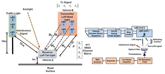
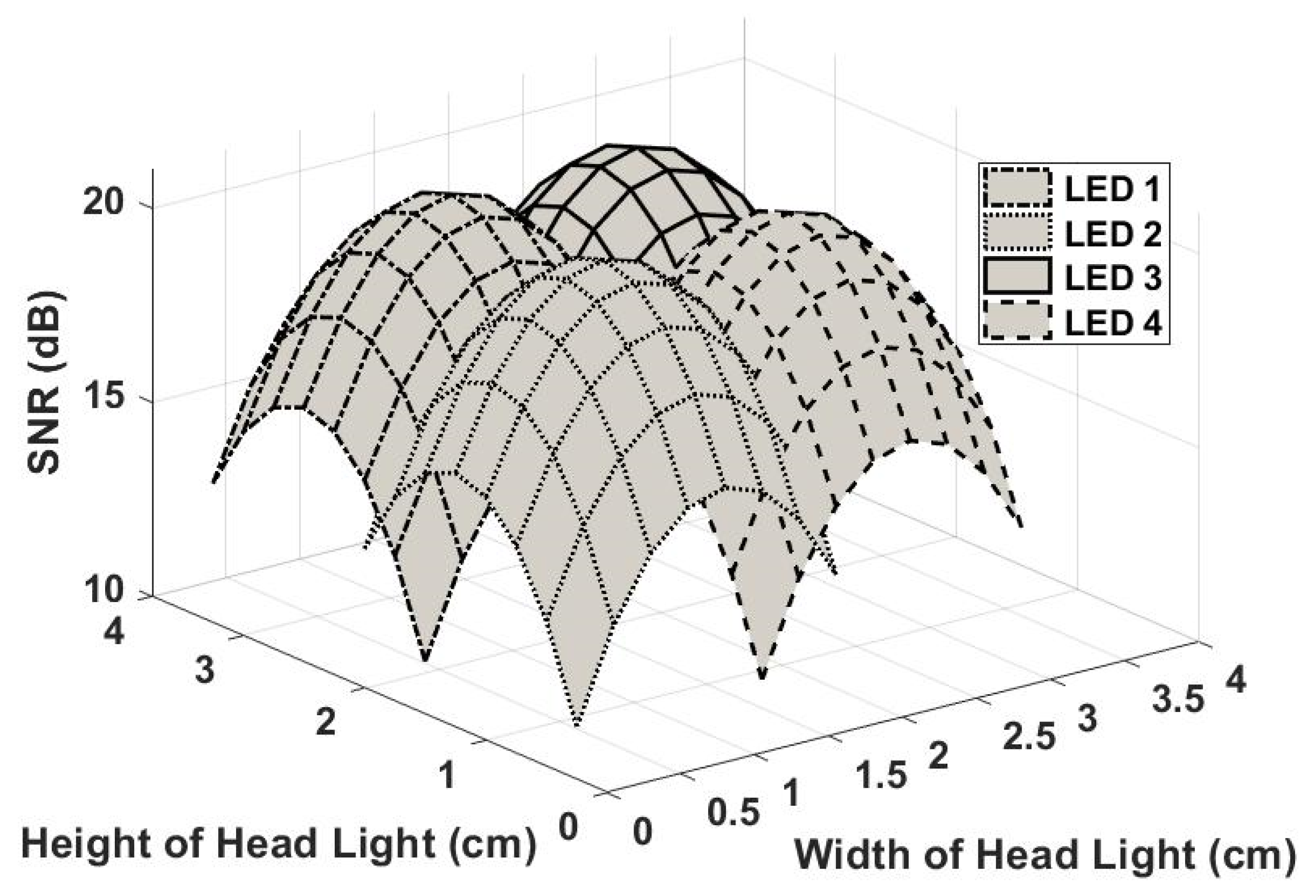
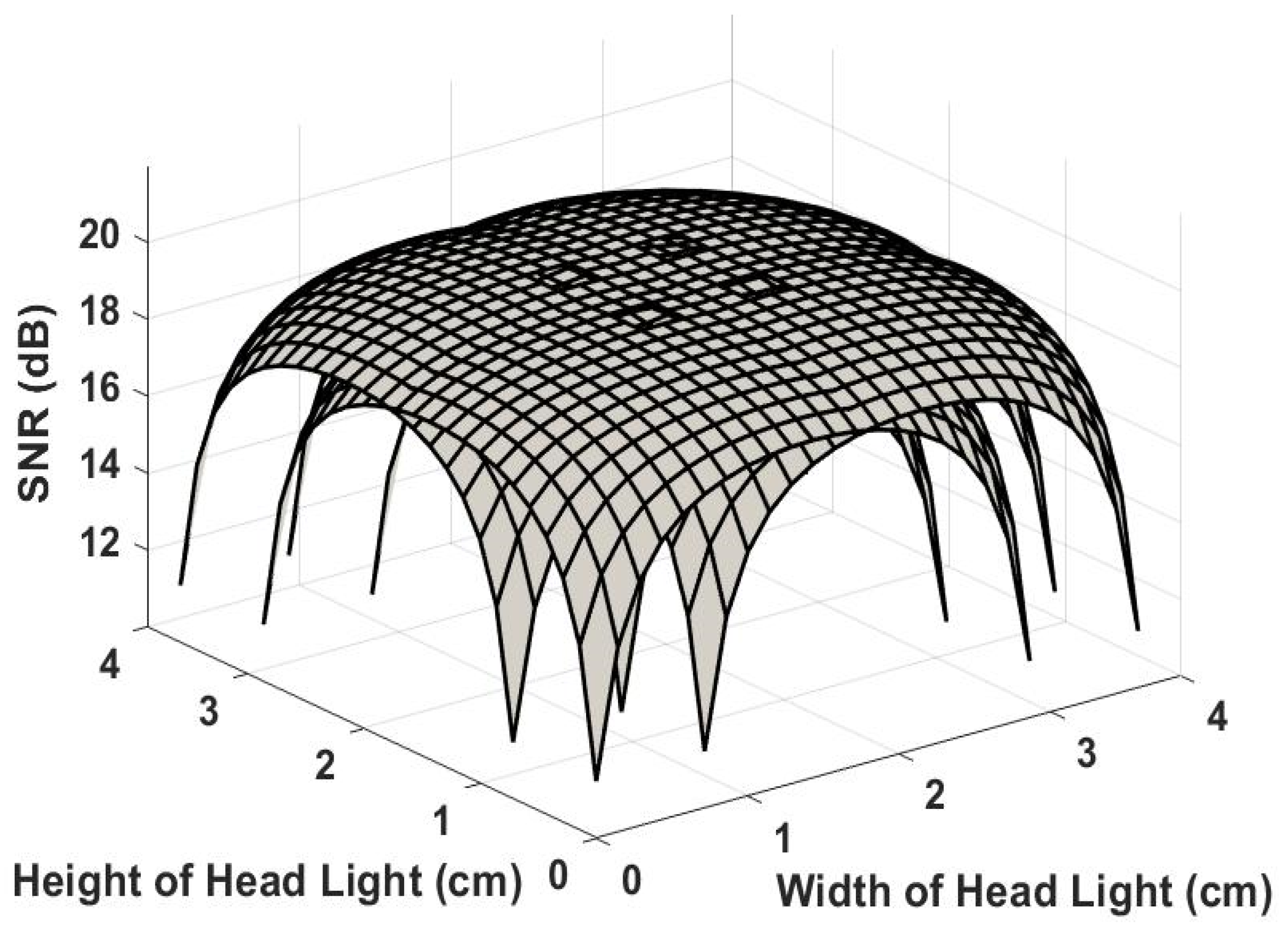
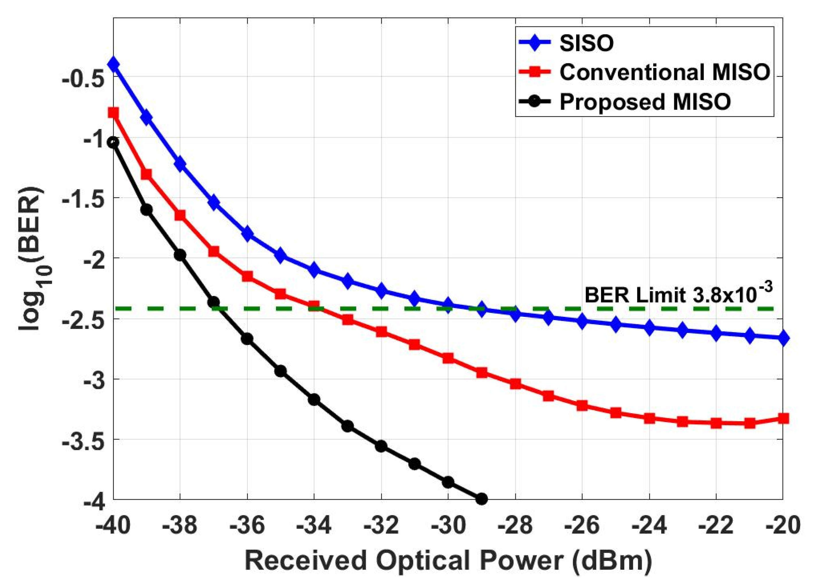
- A 4 × 1 MISO-based VLC system for ITS is considered in this work, to enhance the reliability of the LED-based transmission system.
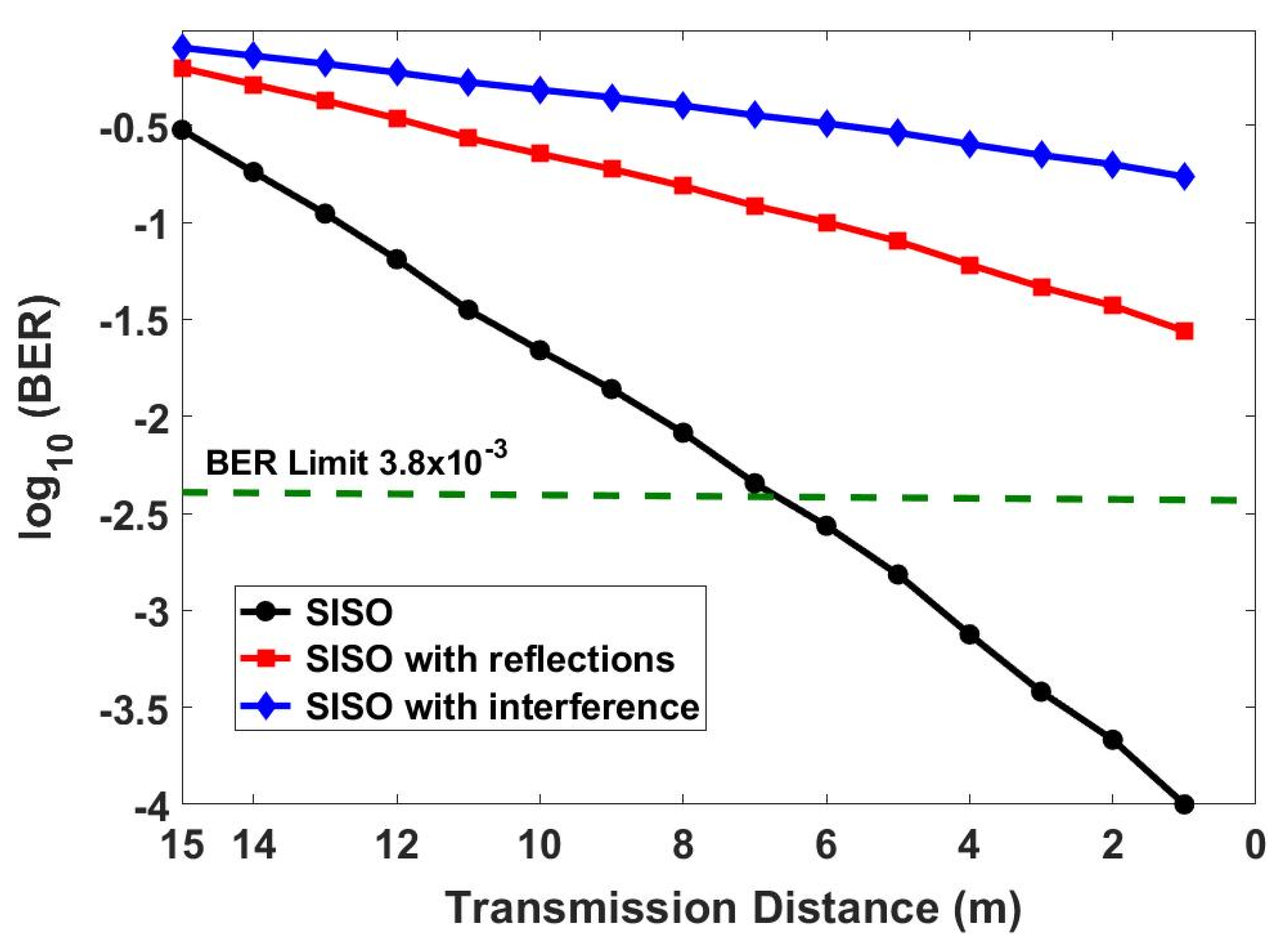
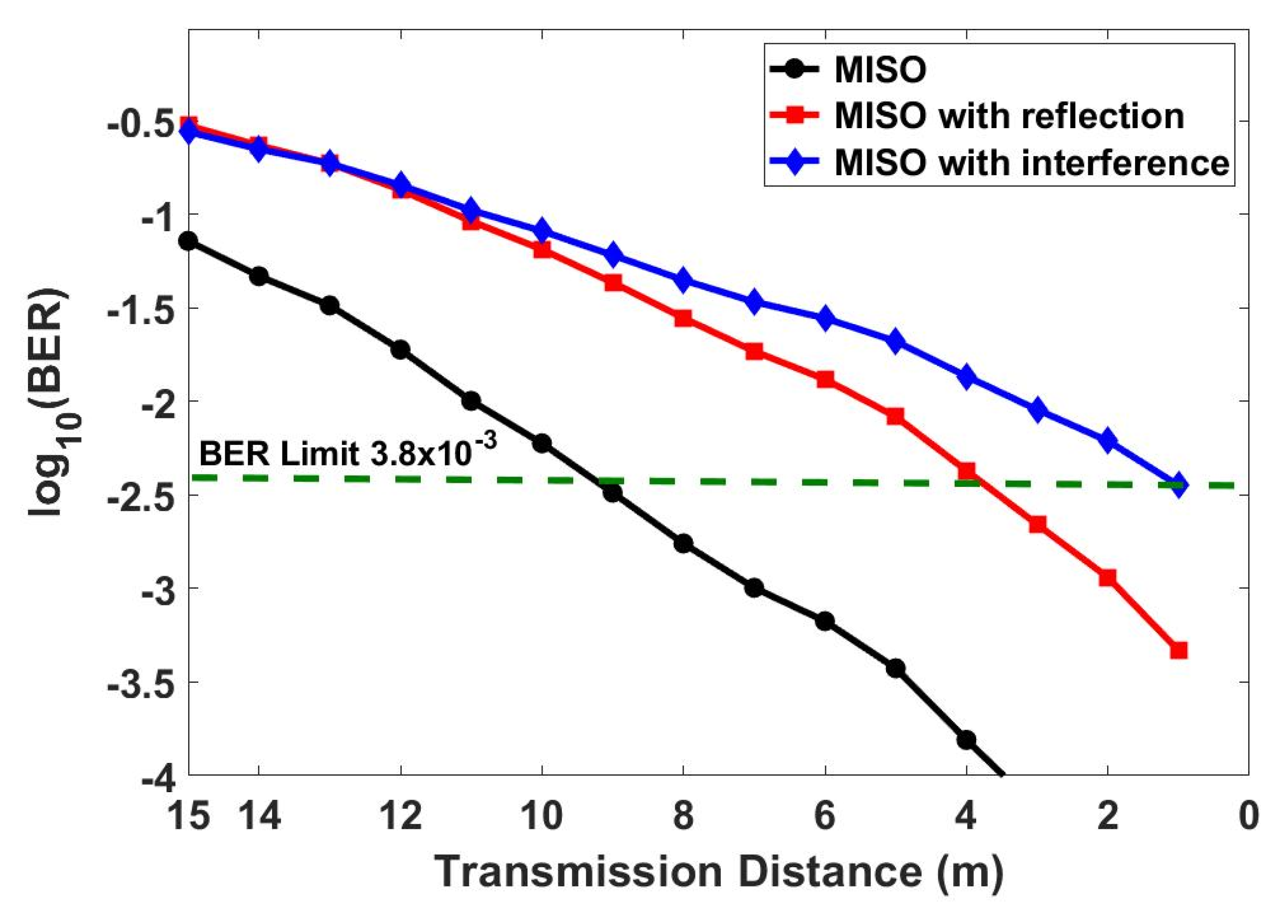
- The effect of link range and interference signal is analyzed in terms of bit error rate (BER) to quantify the performance improvement due to the proposed optimal receiver.
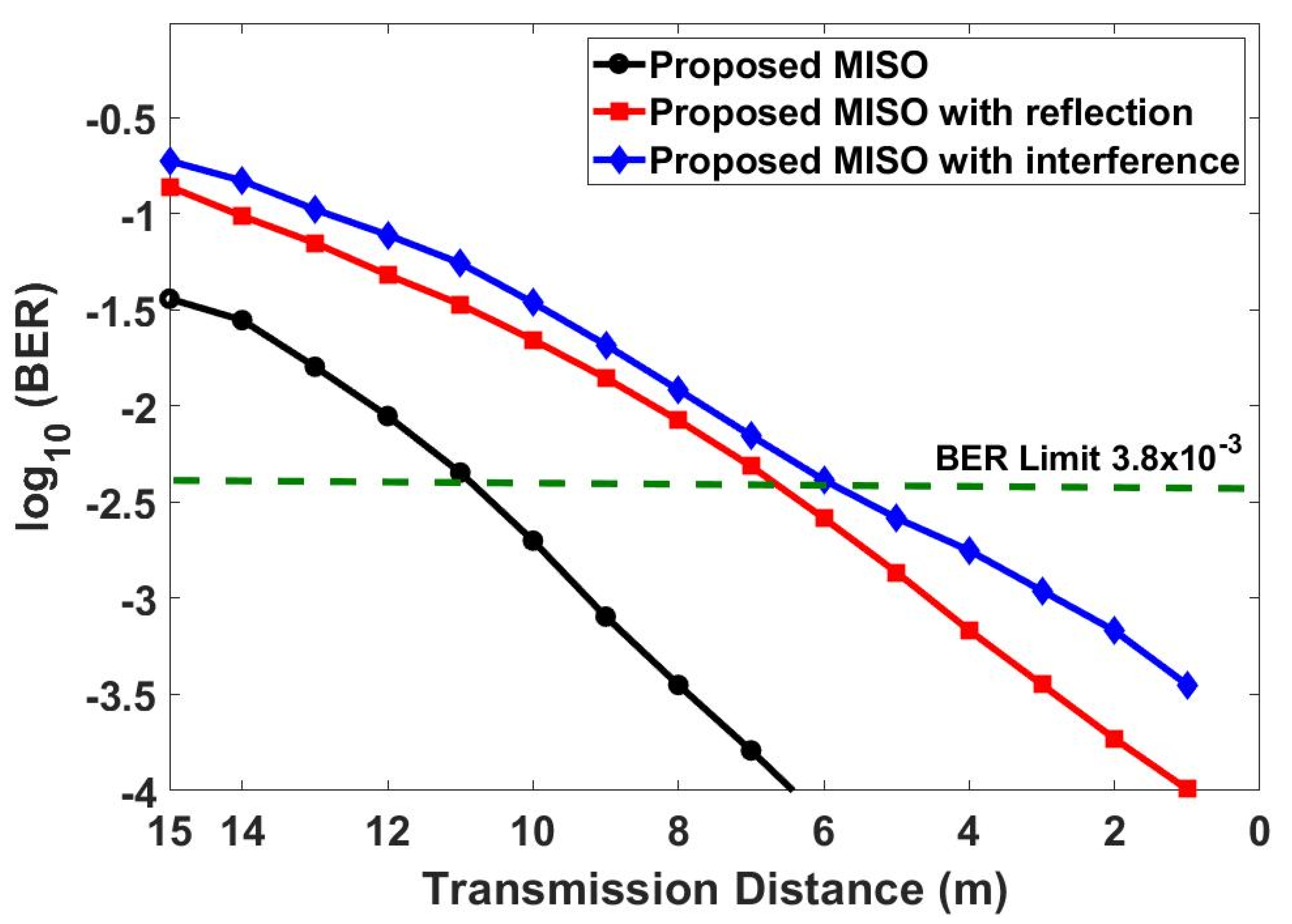
- Another variant of MISO is used with encoding performed at the transmitter side to compare the performance of the system in the presence of channel effects (multipath reflection and optical interference signal) using practical set of parameters for the VLC.
- An optimal design of the MISO receiver is proposed for the VLC transmission and analyzed for different transmission distances and received optical powers for practical channel conditions. The results shows the superiority of the proposed approach over conventional MISO.
3. Analytical Model
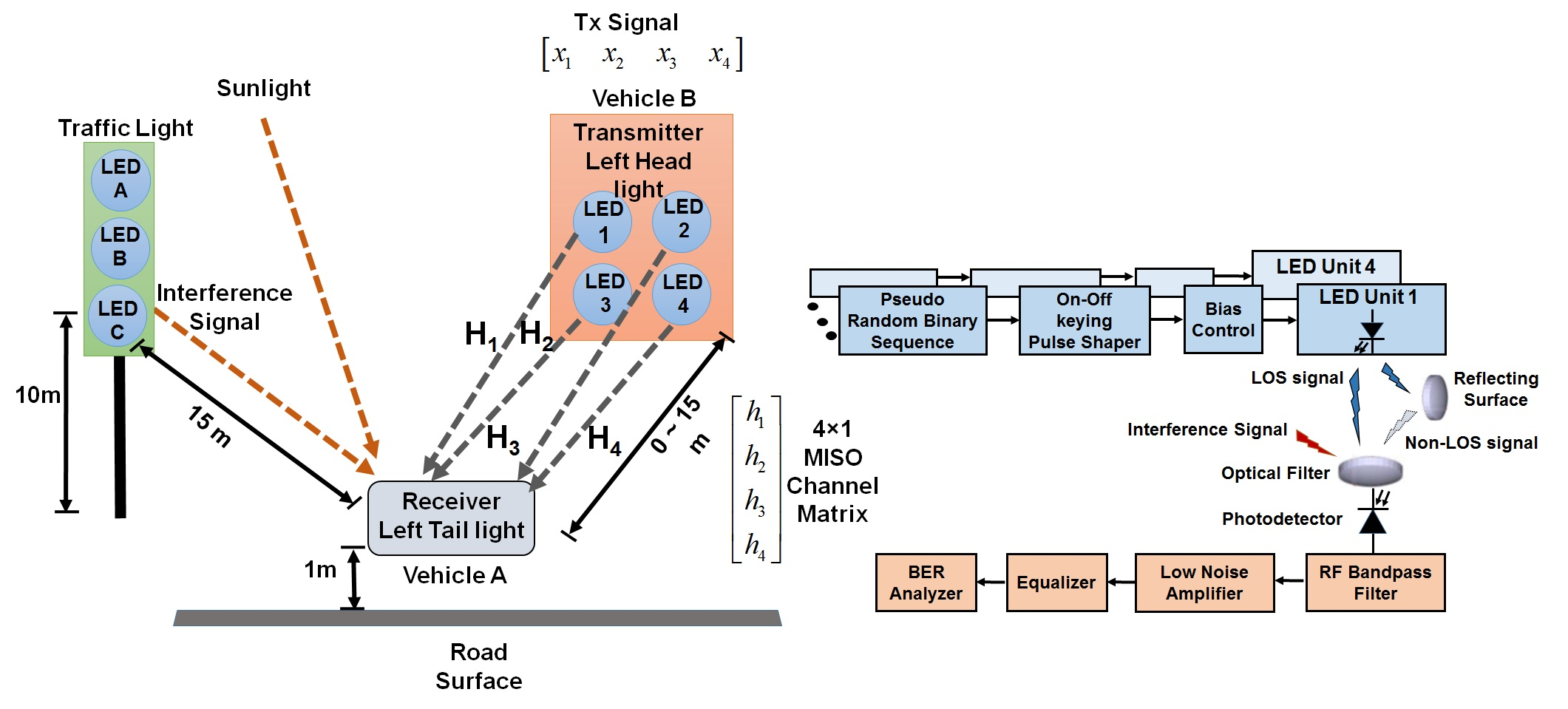
4. Simulation Model
5. Results and Discussion
6. Conclusions
7. Research Limitations and Implications
Author Contributions
Funding
Acknowledgments
Conflicts of Interest
References
- Nawaz, T.; Seminara, M.; Caputo, S.; Mucchi, L.; Cataliotti, F.S.; Catani, J. IEEE 802.15. 7-compliant ultra-low latency relaying VLC system for safety-critical ITS. IEEE Trans. Veh. Technol. 2019, 68, 12040–12051. [Google Scholar] [CrossRef]
- Azmat, M.; Kummer, S. Potential applications of unmanned ground and aerial vehicles to mitigate challenges of transport and logistics-related critical success factors in the humanitarian supply chain. Asian J. Sustain. Soc. Responsib. 2020, 5, 1–22. [Google Scholar] [CrossRef]
- Pojani, D.; Stead, D. Policy design for sustainable urban transport in the global south. Policy Des. Pract. 2018, 1, 90–102. [Google Scholar] [CrossRef]
- Muñoz-Villamizar, A.; Montoya-Torres, J.R.; Faulin, J. Impact of the use of electric vehicles in collaborative urban transport networks: A case study. Transp. Res. Part D 2017, 50, 40–54. [Google Scholar] [CrossRef]
- Matheus, L.E.M.; Vieira, A.B.; Vieira, L.F.M.; Vieira, M.A.M.; Gnawali, O. Visible Light Communication: Concepts, Applications and Challenges. IEEE Commun. Surv. Tutor. 2019, 21, 3204–3237. [Google Scholar] [CrossRef]
- Lorriere, N.; Simon, J.-J.; Betrancourt, N.; Pasquinelli, M.; Chabriel, G.; Barrere, J.; Escoubas, L.; Wu, J.-L.; Bermudez, V.; Ruiz, C. Photovoltaic Solar Cells for Outdoor LiFi Communications. J. Light. Technol. 2020, 38, 1. [Google Scholar] [CrossRef]
- Turan, B.; Narmanlioglu, O.; Ergen, S.C.; Uysal, M. On the Performance of MIMO OFDM-Based Intra-Vehicular VLC Networks. In Proceedings of the 2016 IEEE 84th Vehicular Technology Conference (VTC-Fall), Institute of Electrical and Electronics Engineers (IEEE), Montréal, QC, Canada, 18–21 September 2016; pp. 1–5. [Google Scholar]
- Lv, H.; Feng, L.F.L.; Yang, A.; Guo, P.; Huang, H.; Chen, S.-F. High accuracy VLC Indoor Positioning system with differential detection. IEEE Photonics J. 2017, 9, 1. [Google Scholar] [CrossRef]
- Feng, L.; Yang, H.; Hu, R.Q.; Wang, J. MmWave and VLC-Based Indoor Channel Models in 5G Wireless Networks. IEEE Wirel. Commun. 2018, 25, 70–77. [Google Scholar] [CrossRef]
- Lourenço, N.; Siegel, M.; Gabriel, C.; Pessoa, L.; Silva, B.; Ghassemlooy, Z.; Alves, L.M.L.M.; Zvánovec, S.; Khalighi, M.-A. VLC for indoor positioning: An industrial view on applications. In Visible Light Communications: Theory and Applications; CRC Press: Boca Raton, FL, USA, 2017; pp. 373–404. [Google Scholar]
- Ndjiongue, A.R.; Ferreira, H.C. An overview of outdoor visible light communications. Trans. Emerg. Telecommun. Technol. 2018, 29, e3448. [Google Scholar] [CrossRef]
- Dahri, F.A.; Mangrio, H.B.; Baqai, A.; Umrani, F.A. Experimental Evaluation of Intelligent Transport System with VLC Vehicle-to-Vehicle Communication. Wirel. Pers. Commun. 2018, 106, 1885–1896. [Google Scholar] [CrossRef]
- Tebruegge, C.; Memedi, A.; Dressler, F. Reduced Multiuser-Interference for Vehicular VLC Using SDMA and Matrix Headlights. In Proceedings of the 2019 IEEE Global Communications Conference (GLOBECOM), Institute of Electrical and Electronics Engineers (IEEE), Taipei, Taiwan, 7–11 December 2019; pp. 1–6. [Google Scholar]
- Habib, U.; Steeg, M.; Stohr, A.; Gomes, N.J. Radio-over-fiber-supported 60GHz multiuser transmission using leaky wave antenna. In Proceedings of the 2017 International Topical Meeting on Microwave Photonics (MWP), Institute of Electrical and Electronics Engineers (IEEE), Beijing, China, 23–26 October 2017; pp. 1–4. [Google Scholar]
- Ali, F.; Ahmad, S.; Muhammad, F.; Abbas, Z.H.; Habib, U.; Kim, S. Adaptive Equalization for Dispersion Mitigation in Multi-Channel Optical Communication Networks. Electronics 2019, 8, 1364. [Google Scholar] [CrossRef]
- Sushanth, K.S.; Chockalingam, A. Multiple-LED Complex Modulation Schemes for Indoor MIMO VLC Systems. In Proceedings of the IEEE International Conference on Communications (ICC), Shanghai, China, 20–24 May 2019; pp. 1–6. [Google Scholar]
- Cha, J.; Vinayagam, M. LED-ID Technology for IEEE802. 15.7 m OWC. IEEE COMSOC MMTC E-Lett. 2018, 13, 29–33. [Google Scholar]
- Cuba-Zúñiga, D.J.; Mafra, S.B.; Mejía-Salazar, J.R. Cooperative Full-Duplex V2V-VLC in Rectilinear and Curved Roadway Scenarios. Sensors 2020, 20, 3734. [Google Scholar] [CrossRef]
- Ivascu, C.O.; Ursutiu, D.; Samoila, C. Improve VLC LiFi Performance for V2V Communication. In Cyber-Physical Systems and Digital Twins (Lecture Notes in Networks and Systems); Springer: Basel, Switzerland, 2019; Volume 80, pp. 315–329. [Google Scholar] [CrossRef]
- Karbalayghareh, M.; Miramirkhani, F.; Eldeeb, H.B.; Kizilirmak, R.C.; Sait, S.M.; Uysal, M. Channel Modelling and Performance Limits of Vehicular Visible Light Communication Systems. IEEE Trans. Veh. Technol. 2020, 69, 1. [Google Scholar] [CrossRef]
- Wu, L.; Zhang, Z.; Dang, J.; Liu, H. Blind Interference Alignment for Multiuser MISO Indoor Visible Light Communications. IEEE Commun. Lett. 2017, 21, 1039–1042. [Google Scholar] [CrossRef]
- Habib, U.; Aighobahi, A.E.; Wang, C.; Gomes, N.J. Radio over fiber transport of mm-Wave 2 × 2 MIMO for spatial diversity and multiplexing. In Proceedings of the IEEE International Topical Meeting on Microwave Photonics (MWP), Long Beach, CA, USA, 31 October–3 November 2016; pp. 39–42. [Google Scholar]
- Ma, S.; Zhang, T.; Lu, S.; Li, H.; Wu, Z.; Li, S. Energy Efficiency of SISO and MISO in Visible Light Communication Systems. J. Light. Technol. 2018, 36, 2499–2509. [Google Scholar] [CrossRef]
- Yang, H.; Chen, C.; Zhong, W.-D.; Alphones, A.; Xie, X. Joint Precoder and Equalizer Design for Multi-User Multi-Cell MIMO VLC Systems. IEEE Trans. Veh. Technol. 2018, 67, 11354–11364. [Google Scholar] [CrossRef]
- Malti, R.; Ekongolo, S.; Ragot, J. Dynamic SISO and MISO system approximations based on optimal Laguerre models. IEEE Trans. Autom. Control. 1998, 43, 1318–1323. [Google Scholar] [CrossRef]
- Battikh, D.B.C.; Kelif, J.M.; Coupechoux, M.; Godlewski, P. Dynamic system performance of SISO, MISO and MIMO Alamouti schemes. In Proceedings of the 34th IEEE Sarnoff Symposium, Princeton, NJ, USA, 2–4 May 2011; pp. 1–5. [Google Scholar]
- Alian, E.H.M.; Saffar, H.E.; Mitran, P. Cross-Band Interference Reduction Trade-Offs in SISO and MISO OFDM-Based Cognitive Radios. IEEE Trans. Wirel. Commun. 2012, 11, 2436–2445. [Google Scholar] [CrossRef]
- Marabissi, D.; Mucchi, L.; Caputo, S.; Nizzi, F.; Pecorella, T.; Fantacci, R.; Nawaz, T.; Seminara, M.; Catani, J. Experimental Measurements of a Joint 5G-VLC Communication for Future Vehicular Networks. J. Sens. Actuator Netw. 2020, 9, 32. [Google Scholar] [CrossRef]
- Avătămăniței, S.-A.; Căilean, A.-M.; Done, A.; Dimian, M.; Prelipceanu, M. Noise Resilient Outdoor Traffic Light Visible Light Communications System Based on Logarithmic Transimpedance Circuit: Experimental Demonstration of a 50 m Reliable Link in Direct Sun Exposure. Sensors 2020, 20, 909. [Google Scholar] [CrossRef]
- Raddo, T.R.; Cimoli, B.; Sirbu, B.; Rommel, S.; Tekin, T.; Monroy, I.T. An end-to-end 5G automotive ecosystem for autonomous driving vehicles. In Proceedings of the SPIE Conference of Broadband Access Communication Technologies XIV by International Society for Optics and Photonics, Princeton, NJ, USA, 2–4 May 2020; Volume 11307, p. 1130705. [Google Scholar]
- Yeh, C.-H.; Wei, L.-Y.; Chow, C.-W. Using a Single VCSEL Source Employing OFDM Downstream Signal and Remodulated OOK Upstream Signal for Bi-directional Visible Light Communications. Sci. Rep. 2017, 7, 15846. [Google Scholar] [CrossRef] [PubMed]
- Li, B.; Wang, J.; Zhang, R.; Shen, H.; Zhao, C.; Hanzo, L. Multiuser MISO Transceiver Design for Indoor Downlink Visible Light Communication Under Per-LED Optical Power Constraints. IEEE Photonics J. 2015, 7, 1–15. [Google Scholar] [CrossRef]
- Jeong, J.U.; Lee, K.S.; Seo, H.D.; Han, D.H.; Lee, K.J. Parallel Coding Scheme for Flicker Mitigation in MIMO-VLC. J. Korea Inst. Intell. Transp. Syst. 2016, 15, 146–154. [Google Scholar] [CrossRef]
- Petrariu, A.I.; Lavric, A.; Coca, E. VLC for vehicular communications: A multiple input multiple output (MIMO) approach. In Proceedings of the 2018 International Conference on Development and Application Systems (DAS), Institute of Electrical and Electronics Engineers (IEEE), Suceava, Romania, 24–26 May 2018; pp. 134–137. [Google Scholar]
- Kowalczyk, M. 2 × 2 MIMO VLC Optical Transmission System Based on LEDs in a Double Role. Acta Phys. Pol. A 2016, 130, 41–44. [Google Scholar] [CrossRef]
- Cui, K.; Chen, G.; Xu, Z.; Roberts, R.D. Line-of-sight visible light communication system design and demonstration. In Proceedings of the IEEE 7th International Symposium on Communication Systems Networks and Digital Signal Processing, Newcastle, UK, 21–23 July 2010; pp. 621–625. [Google Scholar]
- Luo, P.; Ghassemlooy, Z.; le Minh, H.; Bentley, E.; Burton, A.; Tang, X. Bit-error-rate performance of a car-to-car VLC system using 2 × 2 MIMO. Mediterr. J. Comput. Netw. 2015, 11, 400–407. [Google Scholar]
- Zhou, C.; Guo, N.; Qiu, R.C. Experimental Results on Multiple-Input Single-Output (MISO) Time Reversal for UWB Systems in an Office Environment. In Proceedings of the IEEE Military Communications Conference, Washington, DC, USA, 23–25 October 2006; pp. 1–6. [Google Scholar]
- Eroğlu, Y.S.; Güvenç, I.; Şahin, A.; Yapıcı, Y.; Pala, N.; Yüksel, M. Multi-element VLC networks: LED assignment, power control, and optimum combining. IEEE J. Sel. Areas Commun. 2017, 36, 121–135. [Google Scholar] [CrossRef]
- Vegni, A.M.; Biagi, M. Optimal LED placement in indoor VLC networks. Opt. Express 2019, 27, 8504–8519. [Google Scholar] [CrossRef]
- Muhammad, F.; Ali, F.; Habib, U.; Usman, M.; Khan, I.; Kim, S. Time Domain Equalization and Digital Back-Propagation Method-Based Receiver for Fiber Optic Communication Systems. Int. J. Opt. 2020, 2020, 3146374. [Google Scholar] [CrossRef]
- Stawiarska, E.; Sobczak, P. The Impact of Intelligent Transportation System Implementations on the Sustainable Growth of Passenger Transport in EU Regions. Sustainability 2018, 10, 1318. [Google Scholar] [CrossRef]
- Juan, Z.; Wu, J.; McDonald, M. Socio-economic impact assessment of intelligent transport systems. Tsinghua Sci. Technol. 2006, 11, 339–350. [Google Scholar] [CrossRef]


| Module | Parameter | Symbol | Value |
|---|---|---|---|
| Transmitter | Semi-angle of LED | 50° | |
| Number of LED units for MISO | m | 4 | |
| Angle of irradiance | θ | 35° | |
| Angle of incidence | φ | 25° | |
| LED Bandwidth | B | 20 MHz | |
| Noise bandwidth factor | I | 0.5 | |
| Channel | Diffused reflectivity | µ | 0.4 |
| Angle of diffused reflection | Φ | 70° | |
| Distance between transmitter and receiver | D | 0–15 m | |
| Receiver | Responsivity | R | 0.6 A/W |
| FOV of the PD | Δ | 20° | |
| PD aperture diameter | A | 10 cm | |
| RF Bessel filter order | n | 4 |
© 2020 by the authors. Licensee MDPI, Basel, Switzerland. This article is an open access article distributed under the terms and conditions of the Creative Commons Attribution (CC BY) license (http://creativecommons.org/licenses/by/4.0/).
Share and Cite
Irfan, M.; Habib, U.; Muhammad, F.; Ali, F.; Alwadie, A.S.; Ullah, S.; Glowacz, A.; Glowacz, W. Optical-Interference Mitigation in Visible Light Communication for Intelligent Transport Systems Applications. Energies 2020, 13, 5064. https://doi.org/10.3390/en13195064
Irfan M, Habib U, Muhammad F, Ali F, Alwadie AS, Ullah S, Glowacz A, Glowacz W. Optical-Interference Mitigation in Visible Light Communication for Intelligent Transport Systems Applications. Energies. 2020; 13(19):5064. https://doi.org/10.3390/en13195064
Chicago/Turabian StyleIrfan, Muhammad, Usman Habib, Fazal Muhammad, Farman Ali, Abdullah S Alwadie, Shakir Ullah, Adam Glowacz, and Witold Glowacz. 2020. "Optical-Interference Mitigation in Visible Light Communication for Intelligent Transport Systems Applications" Energies 13, no. 19: 5064. https://doi.org/10.3390/en13195064
APA StyleIrfan, M., Habib, U., Muhammad, F., Ali, F., Alwadie, A. S., Ullah, S., Glowacz, A., & Glowacz, W. (2020). Optical-Interference Mitigation in Visible Light Communication for Intelligent Transport Systems Applications. Energies, 13(19), 5064. https://doi.org/10.3390/en13195064