Article

Multiobjective Optimisation of a Marine Dual Fuel Engine Equipped with Exhaust Gas Recirculation and Air Bypass Systems

by
Sokratis Stoumpos
and
Gerasimos Theotokatos
*
Maritime Safety Research Centre, Department of Naval Architecture, Ocean and Marine Engineering, University of Strathclyde, 100 Montrose Street, Glasgow G4 0LZ, UK
*
Author to whom correspondence should be addressed.
Energies 2020, 13(19), 5021; https://doi.org/10.3390/en13195021
Submission received: 17 June 2020 / Revised: 7 September 2020 / Accepted: 22 September 2020 / Published: 24 September 2020

Abstract

:
Dual fuel engines constitute a viable solution for enhancing the environmental sustainability of the shipping operations. Although these engines comply with the Tier III NOx emissions regulations when operating at the gas mode, additional measures are required to ensure such compliance at the diesel mode. Hence, this study aimed to optimise the settings of a marine four-stroke dual fuel (DF) engine equipped with exhaust gas recirculation (EGR) and air bypass (ABP) systems by employing simulation and optimisation techniques, so that the engine when operating at the diesel mode complies with the ‘Tier III’ requirements. A previous version of the engine thermodynamic model was extended to accommodate the EGR and ABP systems modelling. Subsequently, a combination of optimisation techniques including multiobjective genetic algorithms (MOGA) and design of experiments (DoE) parametric runs was employed to identify both the engine and the EGR/ABP systems settings with the objective to minimise the engine brake specific fuel consumption and reduce the NOx emissions below the Tier III limit. The derived simulation results were employed to analyse the EGR system involved interactions and their effects on the engine performance and emissions trade-offs. A sensitivity analysis was performed to reveal the interactions between considered engine settings and quantify their impact on the engine performance parameters. The derived results indicate that EGR rates up to 35% are required, so that the investigated engine with EGR and ABP systems, when operating at the diesel mode, achieves compliance with the ‘Tier III’ NOx emissions, whereas the associated engine brake specific fuel consumption penalty is up to 8.7%. This study demonstrates that the combination of EGR and ABP systems can constitute a functional solution for achieving compliance with the stringent regulatory requirements and provides a better understating of the underlined phenomena and interactions of the engine subsystems parameters variations for the investigated engine equipped with EGR and ABP systems.

1. Introduction

1.1. Background

Exhaust after-treatment technologies, such as exhaust gas recirculation (EGR) and selective catalytic reduction (SCR) are the main options for the marine engine manufacturers to ensure compliance of the diesel or DF engines (operating in diesel mode) with the current and future environmental requirements. However, these technologies are associated with a number of challenges related to their initial cost, efficiency, reliability, operability, and space requirements.
The SCR is an exhaust gas after-treatment technology that utilises urea–water solution to reduce the NOx emissions [1]. Although it is a highly effective method to reduce the NOx emissions, the system is associated with considerable volume footprint requirements (for the SCR unit, and urea storage tanks), additional weight, increased capital cost [2], as well as engine thermal and pressure drop issues. Moreover, the SCR technology efficiency is highly dependent on the exhaust gas inlet temperature and the system maintenance. On the contrary, the EGR system affects the combustion process by recirculating an amount of the exhaust gas to reduce the oxygen concentration of the working medium entering the engine cylinders, thus decreasing the maximum combustion temperature [3,4]. Based on the review of the pertinent literature and considering that a DF engine typically operates at the diesel mode for a limited time period, the EGR system is considered to be a cost-effective technology for rendering the diesel mode operation of DF engines compliant with the regulatory requirements. On the other hand, as the SCR system is mostly designed and employed for diesel engines, it was considered out of the scope in this study.

1.2. Exhaust Gas Recirculation on Marine Engines

The investigation and implementation of the EGR technology in diesel engines, either alone or combined with other technologies, has mainly been studied for various applications of the automotive and rail industry [5,6,7,8,9,10,11,12,13,14]. The investigation of the EGR system in marine engines has recently attracted focus by the engine manufacturers. A considerable number of studies investigated the two-stroke diesel engines with EGR systems installed, whereas only a limited number of studies focused on the marine four-stroke diesel engines. Therefore, an apparent lack of investigations is noted for the latter engine category.
Hiraoka et al. [15,16] experimentally investigated a low-pressure EGR (LP-EGR) system installed on a marine two-stroke engine, aiming to verify the long-term reliability and durability of the system by sea trials, monitoring the system in actual ship operation. Kaltoft and Preem [17] numerically investigated a high-pressure EGR (HP-EGR) system for a marine two-stroke engine and examined the percentage distribution of the exhaust gases in the turbocharger unit and the EGR system, aiming to identify the EGR rate for ensuring compliance to the International Maritime Organisation (IMO) ‘Tier III’ limits. Higashida et al. [18] studied an HP-EGR system in conjunction with a variable geometry turbine system and a water fuel emulsification system on a two-stroke engine in order to minimise the fuel consumption penalty due to the decrease of the cylinders combustion pressure. Raptotasios et al. [19] conducted a theoretical analysis of a marine two-stroke engine by using a validated multizone combustion model to identify the EGR rate for ensuring compliance with the IMO ‘Tier III’ requirements and examined the EGR system impact on the engine fuel consumption. Feng et al. [20] examined a marine two-stroke engine by employing a one-dimensional model integrated with a CFD model for representing the in-cylinder processes for investigating the effects of the EGR system combined with a two-stage turbocharger and Miller timing. Sun et al. [21] numerically investigated a marine two-stroke engine with an EGR system by using a computational fluid dynamics (CFD) model and examined the NOx emissions reduction for different EGR rates, as well as the impact of advanced start of injection (SOI) on the engine fuel consumption. Ji et al. [22] numerically investigated a low-speed two-stroke diesel engine and examined the effects of Miller cycle, the EGR system, and the intake air humidification coupled with fuel injection strategies on the engine performance using the CFD modelling.
Previous investigations demonstrated that the marine two-stroke diesel engines equipped with an EGR system are capable of complying with IMO ‘Tier III’ requirements, with or without using alternative technologies, for EGR rates varying from 20% to 40%. Although the alternative technologies used in combination with the EGR system can partially compensate the EGR system effects on the engine, the achieved emissions reduction was associated with a brake specific fuel oil consumption (BSFC) increase ranging from 1% to 6% from their reference values. This is attributed to the reduced cylinder combustion pressure due to lower oxygen concentration of the charge air, which, in turn, results in lower engine power output; therefore, a fuel increase is needed for retaining the engine power. Finally, there is a limited number of studies proposing the use of the air bypass system (ABP) along with the EGR system (for two-stroke engines only) [23,24] to improve the engine performance and reduce complexity in comparison with the two-stage turbocharging system.
The EGR system’s effects on the marine four-stroke diesel engines were investigated in [25,26,27,28,29,30,31,32,33,34,35]. Ludu et al. [25] experimentally investigated the operation of a single cylinder engine with HP-EGR and developed a multicylinder four-stroke engine model in AVL Boost for numerically studying the EGR rates satisfying the IMO ‘Tier III’ requirements as well as the EGR system impact on the soot, smoke emissions, and fuel consumption. Tinschmann et al. [26] compared the internal and external mechanisms to reduce the NOx emissions by using a single-cylinder engine model and investigated the EGR system along with Miller timing and two-stage turbocharging. Park et al. [30] numerically examined the effects of an EGR system on a four-stroke engine and its combination with charge air humidification, aiming to achieve compliance with the IMO ‘Tier III’ NOx levels. Pueschel et al. [31] numerically investigated the combination of post-injection strategies on a four-stroke engine equipped with a LP-EGR system in order to decrease the soot emissions. The EGR system was capable of providing EGR rates up to 20% controlled by a pneumatic valve, whereas an EGR blower was activated to achieve EGR rates up to 40%. Furthermore, Rickert et al. [32] numerically examined a four-stroke engine equipped with a two-stage turbocharger and an EGR system, with the main focus to reduce soot emissions by employing a post-injection strategy. Kyrtatos et al. [33] experimentally examined an HP-EGR configuration on a two-stage turbocharged, six-cylinder medium-speed diesel engine in combination with the water fuel emulsification system to reduce the soot emissions. Kaario et al. [34] experimentally investigated the EGR system on a single cylinder of a medium-speed engine with EGR rates up to 30%, whereas advanced SOI was also examined to optimise the engine fuel consumption by using a zero/one-dimensional model set up in GT-ISE.

1.3. Exhaust Gas Recirculation on Dual Fuel Engines

Kumaraswamy and Prasad [36] converted a single-cylinder four-stroke diesel engine to DF and investigated the effects of various diesel–liquefied petroleum gas (LPG) substitution ratios, engine speeds, and loads on the engine BSFC and emissions with the operation of the EGR system in the diesel and gas modes. Yasin et al. [37] conducted experiments on a single-cylinder DF engine by testing the diesel and gas operating modes with and without the EGR system operating, with the aim to examine the impact of the EGR system on the CO and CO2 emissions. Kalsi and Subramanian [38] tested a single-cylinder DF four-stroke engine under gas mode operation at constant speed for EGR rates up to 30% in order to investigate the CO, NOx, hydrocarbon (HC), and smoke emissions trade-offs. Wu et al. [39] used a four-cylinder DF four-stroke engine equipped with a LP-EGR system to investigate its effects on the CO, NOx, and HC emissions for EGR rates up to 20%. Duan et al. [40] developed a detailed zero-dimensional simulation model of a hydrogen-enriched natural gas SI engine and validated it against the experimental data, with the aim to investigate the engine performance and emissions under different EGR systems layouts, including low-pressure and high-pressure EGR systems, both separately and combined. Li et al. [41] performed a quantitative experimental investigation of the effects of compression ratio, EGR, and spark timing strategies on the performance, combustion, and NOx emissions characteristics on a four-stroke SI natural gas engine fuelled with 99% methane content.
These studies indicated that DF engines equipped with EGR systems demonstrated a 70% reduction in the NOx emissions at the diesel mode for EGR rates ranging from 20% to 30%. With regard to the CO and HC emissions, the respective findings demonstrated varying trends depending on the prevailing operating conditions.

1.4. Exhaust Gas Recirculation System Settings Optimisation

The optimisation of the EGR system settings for automotive applications were studied in [42,43,44,45,46,47,48,49,50]. Hiroyasu [42] carried out an optimisation study for a single-cylinder truck engine by employing the neighbourhood cultivation genetic algorithm (NCGA) with the objective to minimise the NOx and soot emissions along with the fuel consumption by controlling the fuel injection shape, the boost pressure, the EGR rate, the start of injection, the injection duration angle, and the swirl ratio. The trade-off between the fuel oil consumption and the NOx emissions was identified and a linear correlation between the fuel consumption and the soot emissions was derived. Yin et al. [43] experimentally investigated a four-cylinder automotive engine to study the effects of the split injection characteristics, the injection pressure, and the EGR rate on the NOx, soot, and fuel consumption, as well as to identify the engine optimal settings. This study concluded that high levels of EGR and a late injection timing lead to simultaneous reduction of NOx and soot with an associated fuel consumption increase. Ibrahim and Bari [44] numerically investigated a four-stroke natural gas SI engine employing cooled-EGR system aiming to optimise the engine compression ratio and ignition timing for obtaining the lowest BSFC accompanied with high power and low NOx emissions. Park et al. [45] proposed a dual-loop EGR system for four-stroke diesel engines that combines the features of HP and LP EGR systems. They investigated the system operation by simulation deriving a response surface model by employing the Latin hypercube sampling as a fractional factorial design of experiment. Subsequently, a multiobjective Pareto analysis was employed to select the engine settings that minimise the NOx emissions and fuel consumption. Jaliliantabar et al. [46] numerically investigated a small single-cylinder four-stroke diesel engine equipped with an EGR system, aiming to optimise the EGR rate and the biodiesel fuel percentage using the nondominated sorting genetic algorithm NSGA-II. Jo et al. [47] proposed an artificial neural network (ANN) using multiple combustion parameters, calculated from the in-cylinder pressure, to estimate the LP-EGR rate of a turbocharged GDI engine. This ANN was trained and validated using experimental data at steady-state conditions. Ayhan et al. [48] experimentally investigated a single-cylinder four-stroke diesel engine performance and emissions characteristics aiming to optimise the proportions of corn oil methyl ester blends, and EGR rates at variable engine loads and speed conditions, using the Taguchi method. Li et al. [49] investigated a reactivity controlled compression ignition engine with EGR system with the objective to mitigate the high pressure rise rate in biodiesel and gasoline-fuelled engines. A parametric (full factorial) optimisation was performed concluding that optimal conditions were obtained with advanced intake valve closing timing and high EGR rate.
Pertinent studies on the EGR system settings optimisation in marine engines are limited. Lei et al. [50] investigated a marine low-speed two-stroke diesel engine with HP-EGR system and its effects on the NOx emissions and BSFC and proposed a cylinder air bypass system to optimise the engine BSFC.

1.5. Research Aim

This study aimed to optimise by employing state-of-the-art simulation tools and optimisation techniques the settings of a large marine four-stroke DF engine equipped with HP-EGR and ABP systems for ensuring its compliance with the Tier III NOx emissions limits when operating in the diesel mode. As the engine was of DF type and it was already optimised to operate in the gas mode, only the addition of the EGR and ABR systems was considered herein, whereas replacing of the engine components (for example the turbocharging system) was considered out of the scope of this study.
This study was based on a modified version of an existing engine thermodynamic model developed for simulating the engine steady state and transient operations in the GT-ISE software [51,52]. In addition, a combinatorial method that employs the nondominated sorting genetic algorithm NSGA III optimisation genetic algorithm along with a fully factorial design of experiments was developed and employed to achieve this study aim.
The novelty of this study stems from the use of simulation model of high fidelity in conjunction with state-of-the art optimisation methods to optimise at the diesel mode the settings of the engine and its EGR/ABP system for achieving compliance with the Tier III NOx emissions with the minimum BSFC penalty. Moreover, the study results analysis led to the delineation of the involved interactions and underlying parameters, as well as the combined effects of the EGR and ABP systems on the engine performance and emissions parameters trade-offs.

2. Research Methodology and Materials

The methodology employed in this study consisted of the following five steps:
  • Reference system selection—the reference system of a large four-stroke DF engine for this investigation was selected and its operational and geometrical characteristics are described below.
  • EGR and ABP systems selection—the appropriate EGR system type for the investigated reference system was selected and is discussed below. The ABP system usage is justified and the engine layout including EGR/ABP systems is presented.
  • Engine and EGR/ABP systems modelling—the modelling of the engine including the EGR/ABP systems was set up and validated.
  • Optimisation process and cases studies—the optimisation process phases, the methods, and tools to be employed, as well as the variables to be considered, were identified. In addition, the case studies for investigation were defined.
  • Optimal EGR/ABP systems and engine settings identification—investigation of the EGR and ABP systems effects on the engine response were carried out by employing the results of the case studies identified in step 4; sensitivity analysis was conducted to quantitatively assess the impact of the optimisation variables on the engine response.

2.1. Reference System

The investigated reference system selected in this study was the Wärtsilä 9L50DF engine (Wärtsilä, Finland Oy) [53]. This is a four-stroke, turbocharged, and intercooled marine DF engine that can operate in either the gas or the diesel mode. The engine exhibits fuel flexibility, and therefore low emissions (Tier III), as well as high efficiency and reliability. Thus, these reasons make 9L50DF an attractive solution for electric power generation and/or ship propulsion [54]. In this study, the selected engine was studied as an electric generator operating at a constant speed (514 r/min). The engine geometrical and operational specifics are reported in the manufacturer product guide [53] and the main engine characteristics are illustrated in Table 1.

2.2. EGR and ABP Systems on Marine Four-Stroke DF Engines

According to the engine manufacturer, the 9L50DF engine (9L50DF, Wärtsilä, Finland Oy) is capable of accommodating an EGR system [53]. To determine the most suitable EGR system layout, the engine type, the fuel type (diesel/gas), the turbocharging system layout (single or two-stage turbocharging), and the turbine type (variable geometry turbine or exhaust gas waste gate valve) must be considered. Furthermore, the turbocharger matching becomes more challenging due to the contradictory engine requirements in the gas and diesel operating modes (with the EGR system deactivated and activated, respectively).
The EGR system investigated in this study was of the HP-EGR type, redirecting a controlled amount of exhaust gas from the exhaust manifold to the inlet manifold via the EGR system loop. The HP-EGR system, accompanied with a suitable control system, was considered the most efficient EGR design in terms of NOx emissions reduction and fuel consumption trade-offs, as indicated in the literature for the specific engine type [55,56].
The EGR system is equipped with an EGR valve, controlled by the engine control system (ECS), and adjusts the recirculated exhaust gas amount to reduce the oxygen concentration of the inlet manifold working medium. Moreover, an exhaust gas cooler is fitted in the EGR system to reduce the exhaust gas temperature (which subsequently enters the EGR blower and the inlet manifold). The HP-EGR blower ensures that the required exhaust gas flow is achieved, whereas the EGR exhaust gas cooler allows the working medium (air and exhaust gases) temperature in the inlet manifold to remain within the limits set by the engine manufacturer.
On the other hand, the air bypass system is usually fitted in small-bore marine engines for preventing compressor surging in case of rapid engine load reduction [57]. The air bypass valve system is not commonly considered in the EGR design; the existing studies focused on either the two-stage turbocharged marine engines or the single-stage turbocharged marine engines that use low EGR rates and supplementary technologies to comply with the IMO ‘Tier III’ NOx emissions limits. However, considering that the investigated engine in the present study was a marine DF engine, its turbocharger needed to match both the gas and diesel mode requirements. For that reason, the T/C matching was primarily performed in the diesel mode based on the targeted boost pressure, whereas the gas mode employed the exhaust gas waste gate (EWG) valve to adjust the boost pressure, thus realising the effective engine–turbocharger matching in both operating modes. Considering that the EGR system operation was activated in the diesel mode, the turbocharger matching proved to be a major challenge during the engine design stage.
Furthermore, preliminary results of this study indicated that the lack of the ABP system on a single-stage turbocharged engine that operates at high EGR rates can lead to an engine–turbocharger mismatch. This was attributed to the reduced turbine exhaust gases energy flow (due to the EGR system operation), which reduces the T/C shaft speed and thus the compressor mass flow and pressure ratio. Therefore, the compressor operating point (when the engine uses the EGR system) was shifted towards the compressor surge line. The ABP system application aims to avoid the turbocharger mismatching and the fitting of a new turbocharger unit (due to the engine and the existing T/C design operational limitations) that will lead to additional capital costs. This is achieved by redirecting a part of the compressed air flow from the compressor outlet to the turbine inlet in order to keep the compressor operating point within the compressor normal operating region, thus avoiding compressor instabilities.
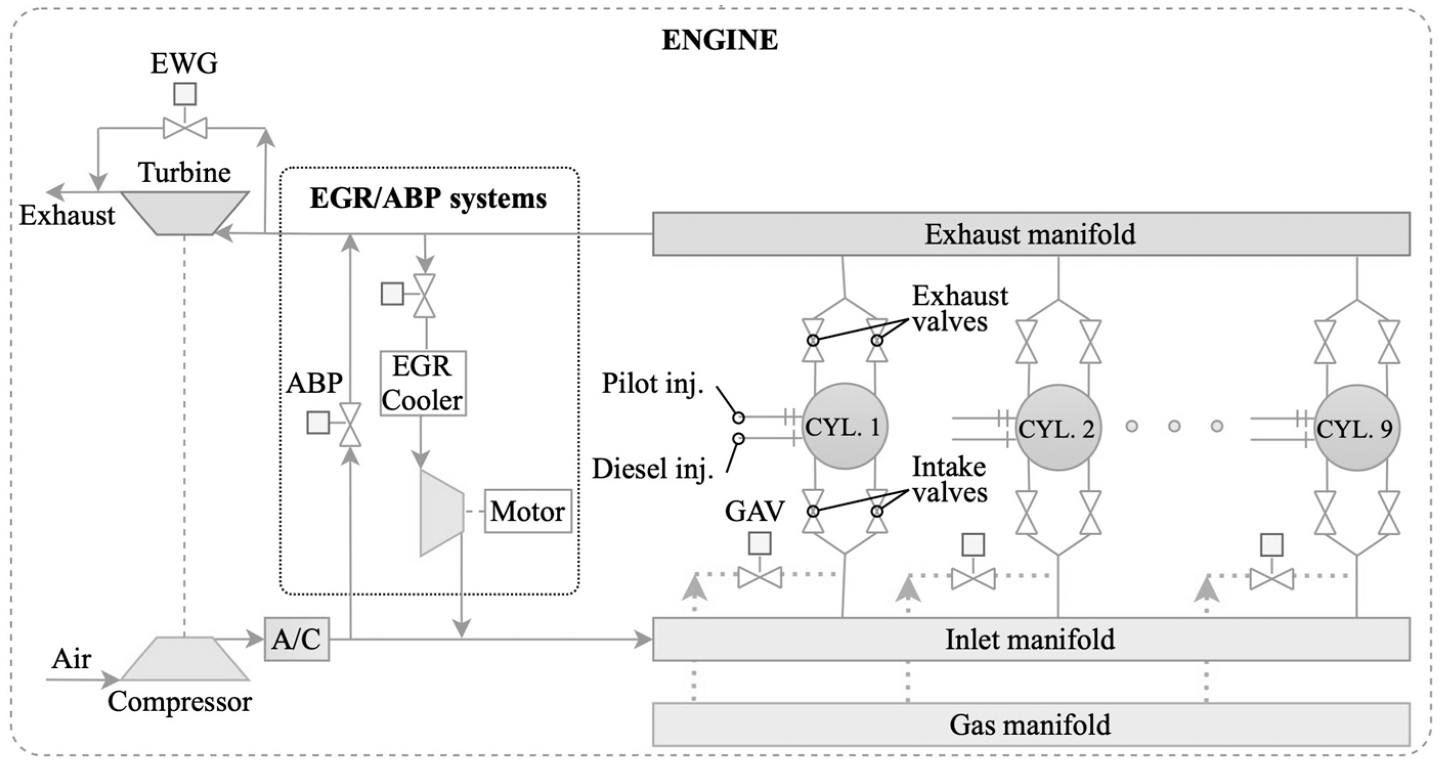
In this respect, the investigated HP-EGR and ABP systems consist of the following components: (a) an exhaust gas cooler installed upstream the EGR blower, (b) an EGR blower driven by an electric motor, (c) an EGR valve that regulates the EGR amount based on the charge air mass flow rate entering the engine, and (d) the ABP valve, and (e) the required piping elements. The investigated engine layout is presented in Figure 1.

3. Modelling

3.1. Engine Modelling

The engine model employed in this study is of the zero/one-dimensional (0D/1D) type and was realised in the GT-ISE (v. 2019, Gamma Technologies, Westmont, Illinois, USA) [58], as this software offers the tools and functionalities to enable the effective engine modelling. The engine model of the investigated engine, without considering the EGR and ABP systems, was previously developed for steady state conditions, as described in [51], and transient conditions, as reported in [52]. The detailed description of the model is reported in the previous publications of the authors [51,52] and therefore, it will not repeated herein.
The processes within the engine cylinders were simulated by employing a zero-dimensional (0D) modelling approach considering the energy and mass conservation equations. The combustion and expansion processes were modelled by considering two zones (the first zone containing the unburnt mixture; the second zone containing the combustion products), whereas a single zone was used for the other cycle processes [59]. The unburned gas zone was assumed to contain the air charge as well as the combustion products from the previous cycle. The cylinder heat transfer, combustion, and friction were modelled employing a variety of well-established models. In specific, the heat transfer coefficient was calculated by employing the Woschni gas to wall heat transfer model [60], whereas the Chen–Flynn model was used to estimate the engine friction mean effective pressure [61]. The NOx emissions were calculated according to the extended Zeldovich mechanism, as reported in [62,63].
The engine manifolds pipes and junction elements were modelled by considering the momentum, the mass, and the energy conservation equations in a one-dimensional (1D) approach. The engine turbocharger compressor and turbine were modelled by using the respective digitised maps. The quasi-steady adiabatic flow equation along with the inlet and exhaust valves profiles (equivalent area versus crank angle) were employed for calculating the respective mass flow rates. For modelling the engine mechanical elements (engine/turbocharger shafts), the respective angular momentum conservation equations were employed for calculating the corresponding rotational speeds.
The existing model was extended to incorporate the modelling of the EGR and ABP systems, whereas the combustion model was extended to accommodate the combustion with the presence of recirculated exhaust gas. These models are described in the following subsections.

3.2. Exhaust Gas Recirculation and Air Bypass Systems Modelling

The modelled layout of the HP-EGR system and ABP system is shown in Figure 1. The EGR and ABP systems piping was modelled by employing a 1D approach, considering the momentum, the mass, and the energy conservation equations.
The EGR cooler was also modelled by employing a 1D approach by considering multiple pipes connected in parallel, where the heat transfer from the exhaust gases to their walls was calculated considering the overall heat transfer coefficient. The cooling water temperature constitute an input parameter that was considered constant during the investigated simulation runs. Information on the input parameters of the EGR cooler were acquired from [64]. It must be noted that the inlet manifold working medium temperature limitation was considered during the EGR and ABP systems design stage. The EGR blower is modelled using its steady state map in a digitised format, which was acquired from [3] and scaled accordingly to match the targeted engine operating parameters.
The EGR rate (mass fraction) was calculated using Equation (1), as defined in [65].
x E G R   =   m ˙ E G R ( m ˙ E G R   +   m ˙ c h a r g e   a i r )
where m ˙ E G R is the EGR exhaust gas mass flow rate and m ˙ c h a r g e   a i r is the charge air mass flow rate.

3.3. Combustion Modelling

As reported in detail in [51,52], the combustion for the diesel operating mode without the EGR system being installed was modelled by using single-Wiebe functions. The ignition delay was approximated by using the data reported in [66,67]. An aggregated approach, which combines both the diesel and pilot fuels combustion was employed. The Wiebe functions parameters include the combustion start, the combustion duration, and the shape factor. As part of the mode calibration process, these parameters were tuned at each operating point (25%, 50%, 75%, and 100% loads) to match the experimentally measured engine performance parameters (specifically, the maximum cylinder pressure, the brake specific fuel consumption (BSFC), and the indicated mean effective pressure (IMEP)) and subsequently their values were stored in a database. Thus, the combustion in the whole engine envelope could be modelled by using interpolation considering the current engine load and the stored Wiebe function parameters. The employed combustion model was proved to be capable of adequately capturing the combustion processes in the diesel mode (without EGR), as the engine maximum cylinder pressure, BSFC, and IMEP were predicted with satisfactory accuracy with the maximum error found to be around ±3% [51].
The combustion model employed in this study was also based on the single Wiebe function approach, as the use of predictive combustion model (for example a multizone model) necessitates the availability of experimental data for the calibration of the model constants [66,67]. Such data were not available. Other approaches reported in the pertinent literature include the combination of 0D/1D and 3D CFD modelling for the combustion [14,68]. However, such more detailed combustion modelling approaches are associated with a considerable computational effort, and therefore are not recommend for optimisation studies that include a large number of simulation runs, which was the case in this study. Such approaches can be used in a future authors’ work to parametrically investigate specific operating points.
For simulating the engine operation at the diesel mode with the EGR and ABP systems activated, the existing database with the stored parameters of the employed Wiebe functions was further extended to include the single-Wiebe function parameters reflecting the EGR effects in the combustion process. In reference to the pertinent literature review, the reported effects include the reduction of the fuel burning rate, the cylinder maximum pressure, and the engine brake power when EGR is used, whereas the ignition delay and the combustion duration increase due to the composition change of the trapped air–exhaust gas mixture into the engine cylinders. Therefore, to counterbalance the EGR system effects and maintain the engine power, the engine control system must order a fuel injection amount increase, resulting in a higher engine fuel consumption. In this respect, the variation of the cylinders composition must be accompanied by the variation of the combustion profile, in terms of the fraction of the burned fuels (diesel fuel) as well as the ignition delay and the combustion duration [59].
Hence, the combustion model parameters were also calibrated to adequately represent the engine combustion process for steady state conditions at the diesel mode with the EGR system considering 25%, 50%, 75%, and 100% loads, as well as 10%, 15%, and 20% EGR rates (the initial model parameters were also available representing 0% EGR rate) based on reported data in [34,65,69,70]. In this respect, the developed database stored sets of each Wiebe function parameter for 16 operating conditions (four loads and four EGR rates). The combustion model parameters were calculated by employing quadratic interpolation in the load range 25–100% and EGR rate range 0–20%, whereas extrapolation was used for EGR rates above 20%. The employed Wiebe function parameters for diesel mode at 100% engine load are presented in Table 2.

4. Optimisation Process and Case Studies

In order to reduce the engine NOx emissions to the required levels (imposed by the IMO ‘Tier III’ requirements) and simultaneously ensure the optimal engine performance, it is essential to identify and optimise the EGR and ABP systems settings affecting the engine response. Hence, the following variables were considered in this optimisation phase: (a) the EGR and ABP valve openings, that can directly affect the EGR rate, and consequently the NOx emissions, as well as the engine fuel consumption; (b) the EGR blower speed; and (c) the start of injection (SOI)—the reported impact of the SOI variation on the maximum cylinders pressure, and consequently on the engine BSFC, renders SOI a crucial variable for the engine efficiency optimisation when the EGR system operates.
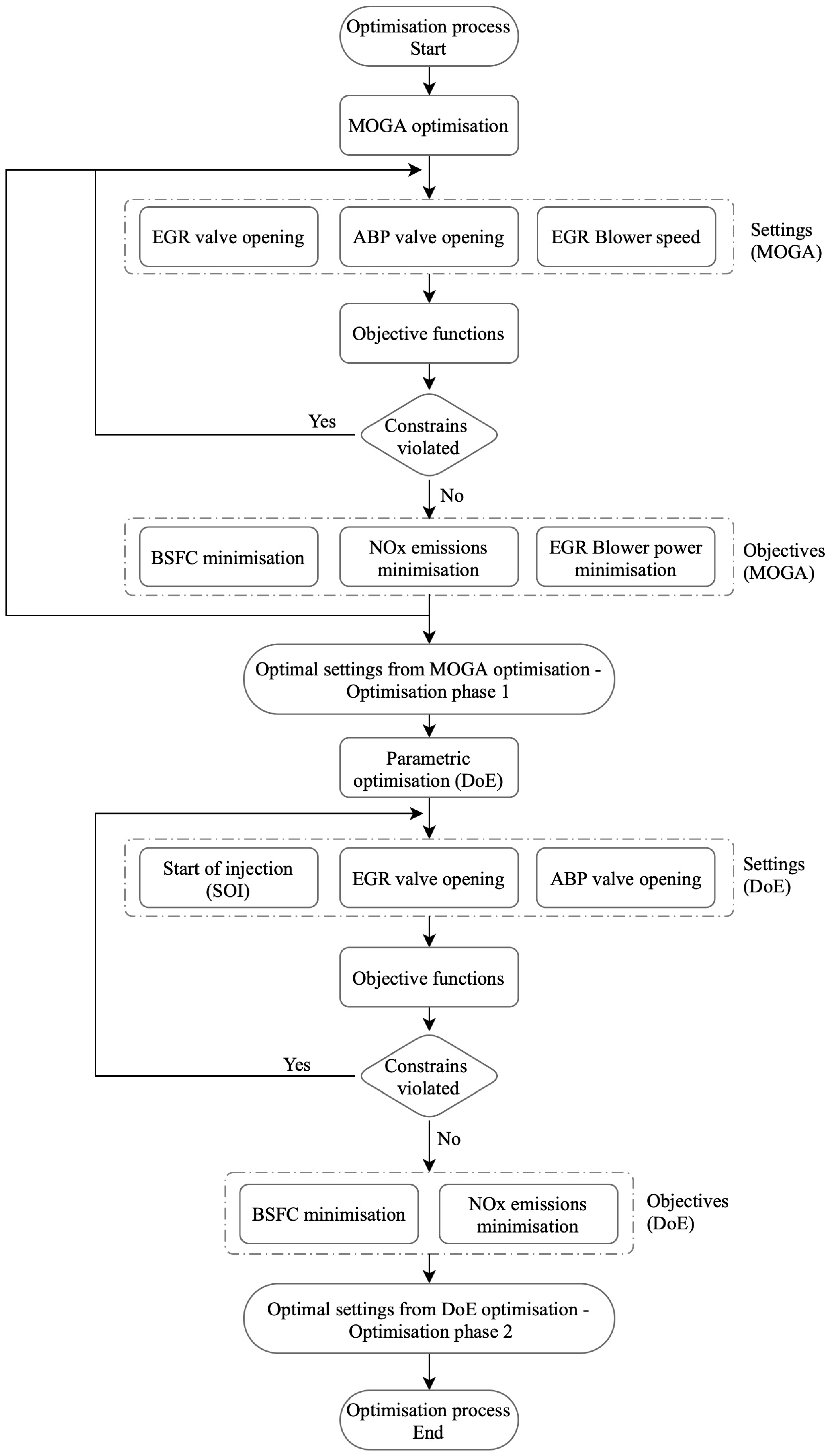
The optimisation phase was carried out considering the following two phases: (a) the optimisation of the EGR and ABP valves openings as well as the EGR blower speed and (b) the SOI optimisation. The reasoning behind this break down into two phases was primarily to permit the investigation of the SOI effects on the BSFC, and secondly to improve the required computational time.
For the first optimisation phase, the built-in GT-ISE multiobjective genetic algorithm (MOGA) optimiser was employed. This method was selected due to the fact that it allows users to maximise, minimise, or target a combination of responses (model parameter outputs) and study their contradicting objectives. In this respect, MOGA is considered one of the most sophisticated and robust optimisation algorithms [58]. The GT-ISE MOGA optimiser employs the nondominated sorting genetic algorithm NSGA-III [71]. The genetic algorithm settings were selected based on recommendations provided in the GT-ISE manual [58] considering the number of variables and simulation cases and are presented in Table 3.
The optimiser objectives include the minimisation of: (a) the NOx emissions, (b) the engine BSFC, and (c) the EGR blower power demand. The EGR and ABP systems settings (i.e., EGR and ABP valves openings) were optimised independently for each load, whereas the EGR blower speed was optimised for all the engine loads. The EGR and ABP valves opening ranges were assumed to be 10–90° and 5–90°, respectively, considering integer steps intervals of 1° for the valve openings. The EGR blower speed range was assumed in the region of 8500–9000 r/min with integer step intervals of 100 r/min. The imposed constraints considered for the optimisation included the acceptable ranges for the compressor surge and choke margins ranges, the EGR rate, as well as the NOx emissions limit (NOx Technical Code [72], E2 test cycle). The expected results from this optimisation stage included the sets of the optimal settings; i.e., the EGR and ABP valves openings, which demonstrated the minimum engine BSFC and the EGR blower power demand.
In the second optimisation phase, the BSFC reduction due to the SOI variations was investigated via parametric runs. The SOI parametric optimisation was performed via the GT-ISE design of experiments (DoE) optimiser employing the ‘full factorial’ method. The simulation runs were performed for a SOI range 20–12°CA bTDC, in integer intervals of 1°CA. The increase of the maximum cylinder pressure as a result of advanced SOI was expected to be accompanied by a minor NOx emissions increase. Thus, the EGR and ABP valves openings were also considered in the DoE parametric runs to compensate this NOx emissions increase.
Both optimisation phases were performed at 25%, 50%, 75%, and 100% engine loads for steady state conditions (case studies 1–4 and 5–8 for MOGA and DoE, respectively). The followed optimisation process flowchart is illustrated in Figure 2, whereas the optimisation process variables and their considered ranges are provided in Table 4.

5. Results and Discussion

5.1. Models Validation

The engine thermodynamic model validation was performed for a number of steady state operating points (25%, 50%, 75%, and 100% load) as presented in [51]. The performance and emissions parameters were calculated and compared with the respective data experimentally obtained from the engine shop tests. The comparison between the measured and the predicted parameters demonstrated that the maximum percentage error was less than 3.5%, thus indicating that the model provides adequate accuracy in all the investigated steady state operating points.
Due to lack of measured data with the engine operation with EGR, the model validation under EGR system operation was qualitatively performed based on the available data from the literature [34,65,69,70]. In this respect, the generated results were compared against published data demonstrating similar trends in the engine response due to EGR system operation.

5.2. Optimisation Case Studies Results

The optimal EGR and ABP systems settings derived from the two discrete optimisation phases (case studies 1–4 and 5–8) are presented in Table 5. The derived results (normalised BSFC against normalised NOx emissions) from the MOGA optimisation results and the DoE parametric investigation results for the 100% engine load are presented in Figure 3. In the same figure, the points of the Pareto front are shown with the square symbols, whereas the failed designs correspond to the cases where the simulation runs did not converge. The MOGA optimisation results, in specific the derived Pareto front points, were employed to select the EGR and ABP systems settings ranges, so that the engine operation marginally complied with the ‘Tier III’ limits whilst achieving the minimum possible BSFC value.
For the DoE parametric investigation results, it was deduced that the derived BSFC variation was negligible for SOI values in the range 15–20°CA bTDC, therefore this value was chosen as the optimal SOI for the 50%, 75%, and 100% loads. At 25% load, the reference value (12°CA bTDC) was selected due to insignificant variation of the BSFC in the range between 20°CA and 12°CA bTDC. Nevertheless, it must be mentioned that the model limitations related to the combustion modelling should also be considered, as a predictive combustion model could predict more accurately the effects of the SOI variations.
As it is presented in Table 5, the EGR blower that speed resulted in the optimal EGR/ABP systems performance for the range of 25% to 100% engine load was 9000 r/min. The EGR blower power requirements ranged from 0.7% to 2.3% of the engine brake power in the investigated engine loads.
Furthermore, the EGR system valve opening increased as the engine load increased from 25% to 100% load, in order to achieve the required EGR rate as the charge air mass flow rate increases. On the other hand, the ABP valve opening demonstrated a low value (almost 0.2; where 1 represented the fully opening) at 25% load, which was attributed to the low charge air mass flow rate, whilst it was responsible for controlling the T/C compressor operating point to avoid the T/C surging effect. However, for engine loads of 50% and higher, it was observed that the ABP valve opening remained at the same levels (due to increased charge air mass flow rate), providing the required charge air mass flow at the inlet manifold to achieve the targeted EGR rate. In this respect, it was inferred that the ABP valve had a direct impact on the charge air mass flow rate, and thus the EGR rated as well as the mitigation of the potential safety implications related to the T/C surging effect.
From the steady state simulations results presented in Table 5. and Figure 4, it can be inferred that the engine operating at the diesel mode with the EGR and ABP systems activated, is capable of complying with the IMO ‘Tier III’ requirements, achieving a 73% reduction in NOx emissions for EGR rates ranging from 31% to 35%. However, the NOx emissions reduction was associated with an increase in the BSFC ranging from 8.4% to 9.9%, considering the respective EGR blower electrical power requirements (the respective BSFC numbers without considering the EGR blower power requirements were found to be 6.1% to 8.7%). This was found to be in accordance with the reported findings in the pertinent literature [34,65]. As shown in Figure 4 top right graph, the implementation of an advanced SOI offered a BSFC reduction from 0.3% up to 1.8%, as the load increased, with the highest BSFC reduction noted at 100% load. Moreover, a moderate increase in the CO2 emissions was observed, ranging from 5.5% to 7.8%, which was attributed to the higher BSFC values. With regard to the exhaust gas temperature, the manufacturer alarm limit was not exceeded in all the investigated cases. For the 50%, 75%, and 100% loads, the exhaust gas temperature demonstrated a reduction ranging from 0.6% to 2.9%, whereas an increase of 9% was noted for the 25% load, which was attributed to the low ABP valve opening. The maximum cylinder pressure and the boost pressure demonstrated similar descending trends, with reductions ranging from 11% to 18.7% and 6.9% to 35%, respectively. The reductions observed in these engine operating parameters were attributed to the lower exhaust gas thermal power to the T/C turbine due to the EGR system operation, which resulted in a lower T/C speed, a lower boost pressure, and eventually reduced the charged air mass flow rate.

5.3. Sensitivity Analysis

Whilst the identification of the optimal EGR/ABP systems settings was significant for the efficient engine operation (due to the effects of these systems on the engine response), the understanding of the relationships between the input variables (EGR/ABP systems settings) and the output parameters (engine performance) is equally important for the design and development of these systems. This study employed a sensitivity analysis (SA), which is defined as a method to measure the impact of uncertainties in one or more input variables on the output variables [73,74].
The employed sensitivity analysis objectives were the following: (a) revealing the interactions between the considered engine settings and quantifying their impact on the engine performance parameters, (b) validation of the optimisation process design, and (c) providing evidence to improve the design of the investigated system.
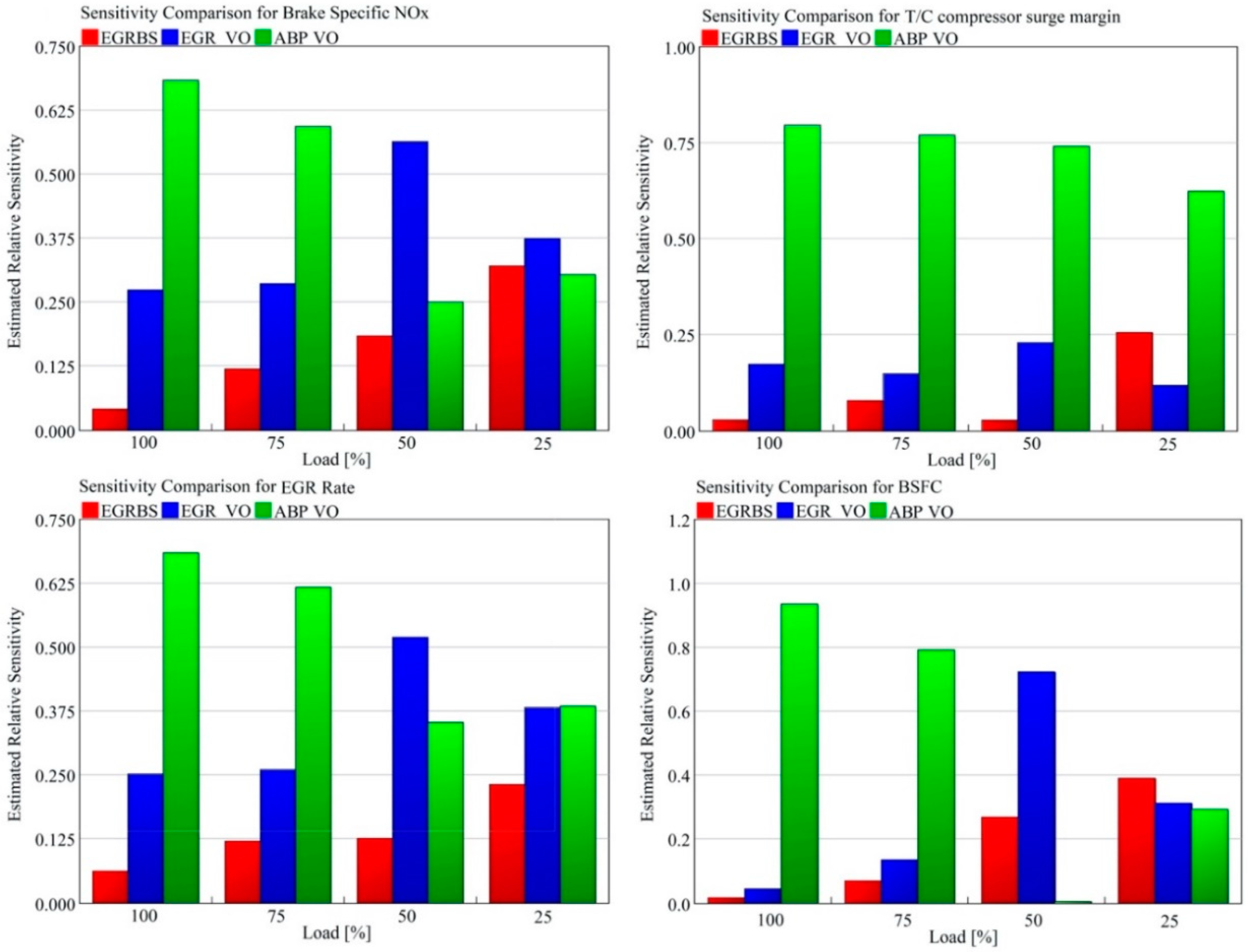
The sensitivity analysis results were generated using the integrated GT-ISE tool, considering all the valid designs investigated in the MOGA optimisation (failed designs were excluded). The input variables of the sensitivity analysis included: (a) the EGR system blower speed (EGRBS), (b) the EGR valve opening (EGR VO), and (c) the ABP valve opening (ABP VO), whereas the output under investigation included: (a) the engine brake NOx emissions, (b) the T/C compressor surge margin, (c) the EGR rate, and (d) the BSFC, for each investigated engine load (100%, 75%, 50%, and 25%).
The sensitivity analysis results (relative sensitivity fraction) are presented in Figure 5. As shown in the top left graph, the brake NOx emissions were mainly affected by the ABP valve opening for the high engine loads (100% and 75%), whereas for the low engine loads (50% and 25%), the EGR valve opening was the most influencing parameter. The former was attributed to the direct impact of the ABP valve opening on the inlet manifold pressure (larger ABP valve opening implies lower inlet manifold pressure), which in turn affected the maximum cylinder pressure and the NOx emissions. For low engine loads the engine manifolds pressure levels were lower, which justified the lower sensitivity exhibited for the ABP valve opening; in these cases, the EGR valve opening sensitivity prevailed. The EGR valve opening directly affected the working medium composition at the inlet manifold (due to exhaust gas recirculation), and therefore the NOx emissions reduction.
By comparing the top and bottom left graphs of Figure 5, the sensitivity of the input parameters for the brake specific NOx emissions and the EGR rate demonstrated similar trends, which was expected as these output parameters are interconnected, where the EGR rate affects the brake NOx emissions. The top right graph of Figure 5 demonstrates that the ABP valve opening sensitivity on the T/C compressor surge margin was the most prevailing parameter in all engine loads. This was attributed to the effect of the ABP system on varying the compressor operating point (higher ABP valve opening implies higher T/C mass flow rate). The EGR valve opening was the second prevailing parameter, demonstrating sensitivity on the T/C compressor margin lower than 0.25. The bottom right graph of Figure 5 demonstrates that the ABP valve opening was the most prevailing parameter that affected the BSFC at high loads, whereas at low loads the EGR valve opening and EGR blower speed were the most prevailing parameters.
With regard to the EGR system blower speed, it was observed that its sensitivity against all the considered output engine operating parameters increased whilst shifting from high to low engine loads. This was mainly attributed to the inlet boost pressure and the exhaust gas pressure reduction as the load decreased, where the EGR blower needed to ensure that the EGR target rate was achieved.

6. Conclusions

This study focused on the optimisation of the engine and EGR/ABP systems settings so that the diesel mode operation of the investigated large marine DF engine complied with the IMO ‘Tier III’ NOx emissions regulations. The modelling and optimisation of the investigated engine were realised in GT-ISE. The optimisation process consisted of two phases; the first dealt with the optimisation of: (a) the EGR valve opening, (b) the ABP valve opening, and (c) the EGR blower speed by using the NSGA-III algorithm, whereas the second considered the optimisation of SOI by using parametric runs based on the full factorial DoE method.
This study revealed the underlying interactions and the combined effects of the EGR and ABP systems to the engine performance and emissions taking into account the involved systems operational limitations. Moreover, this study proved that introducing the minimum modifications in the existing engine, specifically the addition of the EGR and ABP systems whilst retaining the original T/C system, is a functional solution to operate a DF engine at the diesel mode, considering the existing stringent regulatory requirements.
The main findings of this study are summarised as follows:
  • The engine NOx emissions can be reduced by almost 73% when using an EGR in combination with an ABP system, demonstrating compliance with the ‘Tier III’ requirements.
  • The required EGR rates to achieve ‘Tier III’ compliance range from 31% to 35% as a function of the engine load.
  • The obtained NOx emissions reduction was associated with a BSFC increase from 8.4% to 9.9% considering the respective EGR blower electrical power requirements, in comparison to the diesel mode operation without EGR/ABP systems activation. The respective BSFC penalty without considering the EGR blower power requirements were found to be 6.1% to 8.7%.
  • The advance of SOI offered fuel savings ranging from 0.3% up to 1.8% as the load increased, with the highest BSFC reduction obtained at 100% load.
  • The followed optimisation process was proven to be computationally effective and resulted in identifying the Pareto front and optimal system settings.
  • The sensitivity analysis verified that the most sensitive parameters were the ones considered in the optimisation process, thus validating the followed approach.
The proposed solution can provide a functional approach to ship owners/operators for addressing the challenges emanating from the recent regulatory framework, whilst considering the associated cost of other alternative solutions.
The limitations of this study are mainly related to the employed combustion modelling, which was of the ‘semipredictive’ type. This model was selected due to lack of extensive experimental data, which are required to facilitate the model constants calibration [66,75] as well as to retain a low computational cost for the optimisation process. In addition, the methane emissions generated by the investigated engine were not included under this study scope as considering the employed zero-dimensional combustion model, the expected accuracy would be questionable.
Future studies can include the use of a ‘predictive’ (phenomenological) combustion subject to the availability of that sufficient data for its calibration, the investigation of engine operation under transient conditions, as well as the study of the feasibility and cost-effectiveness of the proposed solution.

Author Contributions

Conceptualization, S.S. and G.T.; methodology, S.S. and G.T.; software, S.S.; validation, S.S. and G.T.; formal analysis, S.S. and G.T.; writing—original draft preparation, S.S. and G.T.; writing—review and editing, S.S. and G.T.; visualization, S.S.; supervision, G.T.; project administration, G.T. All authors have read and agreed to the published version of the manuscript.

Funding

This research received no external funding.

Acknowledgments

The authors greatly acknowledge the funding from DNV GL AS and RCCL for the MSRC establishment and operation. The opinions expressed herein are those of the authors and should not be construed to reflect the views of DNV GL AS and RCCL. Gamma Technologies support is also greatly acknowledged by the authors.

Conflicts of Interest

The authors declare no conflict of interest.

Abbreviations

0DZero-dimensional
1DOne-dimensional
ABPAir Bypass System
BMEPBrake Mean Effective Pressure
BSFCBrake Specific Fuel Consumption
bTDCBefore top dead centre
CACrank Angle
CFDComputational Fluid Dynamics
CO2Carbon Dioxide
DF Dual Fuel
DoEDesign of Experiments
EGRExhaust Gas Recirculation
EWGExhaust gas waste gate valve
GTGamma Technologies
HP-EGRHigh Pressure Exhaust Gas Recirculation
IMEPIndicated Mean Effective Pressure
IMOInternational Maritime Organization
LP-EGRLow Pressure Exhaust Gas Recirculation
MOGAMultiobjective Genetic Algorithm
NGNatural Gas
NOxNitrogen oxides emissions
NSGANondominated Sorting Genetic Algorithm
PEEngine brake power
SCRSelective Catalytic Reduction
SOIStart of Injection
T/CTurbocharger

References

  1. Pakarinen, R. IMO Tier III and Beyond. Available online: https://www.wartsila.com/twentyfour7/environment/imo-tier-iii-and-beyond (accessed on 17 June 2019).
  2. Rudrabhate, S.D.; Chaitanya, S.V. Comparison between EGR & SCR Technologies. In Proceedings of the International Conference on Ideas, Impact and Innovation in Mechanical Engineering (ICIIIME), Pune, India, 1–2 June 2017; pp. 856–861. [Google Scholar]
  3. MAN. Tier III Two-Stroke Technology. Available online: https://marine.mandieselturbo.com/docs/librariesprovider6/technical-papers/tier-iii-two-stroke-technology.pdf?sfvrsn=18 (accessed on 17 June 2019).
  4. EGCSA. NOx Reduction by Exhaust Gas Recirculation—MAN. Explains. Available online: https://www.egcsa.com/exhaust-gas-recirculation-explained/ (accessed on 17 June 2019).
  5. Ladommatos, N.; Abdelhalim, S.; Zhao, H. The Effects of Exhaust Gas Recirculation on Diesel Combustion and Emissions. Int. J. Engine Res. 2000, 1, 107–126. [Google Scholar] [CrossRef]
  6. Gautier, P.; Albrecht, A.; Chasse, A.; Moulin, P.; Pagot, A.; Fontvieille, L.; Issartel, D. A Simulation Study of the Impact of LP EGR on a Two-Stage Turbocharged Diesel Engine. Oil Gas Sci. Technol.-Rev. IFP 2009, 64, 361–379. [Google Scholar] [CrossRef]
  7. Maiboom, A.; Tauzia, X. NOx and PM Emissions Reduction on an Automotive HSDI Diesel Engine with Water-in-Diesel Emulsion and EGR: An Experimental Study. Fuel 2011, 90, 3179–3192. [Google Scholar] [CrossRef]
  8. Zamboni, G.; Capobianco, M. Influence of High and Low Pressure Egr and Vgt Control on in-Cylinder Pressure Diagrams and Rate of Heat Release in an Automotive Turbocharged Diesel Engine. Appl. Therm. Eng. 2013, 51, 586–596. [Google Scholar] [CrossRef]
  9. Beatrice, C.; Rispoli, N.; Di Blasio, G.; Patrianakos, G.; Kostoglou, M.; Konstandopoulos, A.; Imren, A.; Denbratt, I.; Palacín, R. Emission Reduction Technologies for the Future Low Emission Rail Diesel Engines: EGR vs SCR. SAE Tech. Pap. Ser. 2013. [Google Scholar] [CrossRef]
  10. Samokhin, S.; Sarjovaara, T.; Zenger, K.; Larmi, M. Modeling and Control of Diesel Engines with a High-Pressure Exhaust Gas Recirculation System. IFAC Proc. Vol. 2014, 47, 3006–3011. [Google Scholar] [CrossRef]
  11. Buenaventura, F.C.; Witrant, E.; Talon, V.; Dugard, L. Air Fraction and EGR Proportion Control for Dual Loop EGR Diesel Engines. Ing. Univ. 2015, 19, 115. [Google Scholar] [CrossRef] [Green Version]
  12. Konstandopoulos, A.G.; Kostoglou, M.; Beatrice, C.; Di Blasio, G.; Imren, A.; Denbratt, I. Impact of Combination of EGR, SCR, and DPF Technologies for the Low-Emission Rail Diesel Engines. Emiss. Control Sci. Technol. 2015, 1, 213–225. [Google Scholar] [CrossRef] [Green Version]
  13. Thangaraja, J.; Kannan, C. Effect of Exhaust Gas Recirculation on Advanced Diesel Combustion and Alternate Fuels—A review. Appl. Energy 2016, 180, 169–184. [Google Scholar] [CrossRef]
  14. Beatrice, C.; Rispoli, N.; Di Blasio, G.; Konstandopoulos, A.G.; Papaioannou, E.; Imren, A. Impact of Emerging Engine and After-Treatment Technologies for Improved Fuel Efficiency and Emission Reduction for the Future Rail Diesel Engines. Emiss. Control Sci. Technol. 2016, 2, 99–112. [Google Scholar] [CrossRef] [Green Version]
  15. Hiraoka, N.; Miyanagi, A.; Kuroda, K.; Ito, K.; Nakagawa, T.; Ueda, T. The World’s First Onboard Verification Test of UE Engine with Low Pressure EGR complied with IMO’s NOx Tier III Regulations. Mitsubishi Heavy Ind. 2016, 53, 40. [Google Scholar]
  16. Hiraoka, N.; Ueda, T.; Nakagawa, T.; Ito, K. Development of Low Pressure Exhaust Gas Recirculation System for Mitsubishi UE Diesel Engine. In Proceedings of the 28th CIMAC World Congress on Combustion Engine Technology, Helsinki, Finland, 6–10 June 2016. [Google Scholar]
  17. Kaltoft, J.; Preem, M. Development of Integrated EGR System for Two-Stroke Diesel Engines. In Proceedings of the 27th CIMAC World Congress on Combustion Engine Technology, Shanghai, China, 13–17 May 2013. [Google Scholar]
  18. Higashida, M.; Nakamura, T.; Onishi, I.; Yoshizawa, K.; Takata, H.; Hosono, T. Newly Developed Combined EGR & WEF System to comply with IMO NOx Regulation Tier 3 for Two-stroke Diesel Engine. In Proceedings of the 27th CIMAC World Congress on Combustion Engine Technology, Shanghai, China, 13–17 May 2013. [Google Scholar]
  19. Raptotasios, S.; Sakellaridis, N.F.; Papagiannakis, R.G.; Hountalas, D.T. Application of a Multi-Zone Combustion Model to Investigate the Nox Reduction Potential of Two-Stroke Marine Diesel Engines Using EGR. Appl. Energy 2015, 157, 814–823. [Google Scholar] [CrossRef]
  20. Feng, L.; Tian, J.; Long, W.; Gong, W.; Du, B.; Li, D.; Chen, L. Decreasing NOx of a Low-Speed Two-Stroke Marine Diesel Engine by Using In-Cylinder Emission Control Measures. Energies 2016, 9, 304. [Google Scholar] [CrossRef] [Green Version]
  21. Sun, X.; Liang, X.; Shu, G.; Lin, J.; Wang, Y.; Wang, Y. Numerical Investigation of Two-Stroke Marine Diesel Engine Emissions Using Exhaust Gas Recirculation at Different Injection Time. Ocean Eng. 2017, 144, 90–97. [Google Scholar] [CrossRef]
  22. Ji, W.; Li, A.; Lu, X.; Huang, Z.; Zhu, L. Numerical Study on NOx and Isfc Co-Optimization for a Low-Speed Two-Stroke Engine via Miller Cycle, EGR, Intake Air Humidification, and Injection Strategy Implementation. Appl. Therm. Eng. 2019, 153, 398–408. [Google Scholar] [CrossRef]
  23. Nielsen, K.V.; Blanke, M.; Eriksson, L.; Vejlgaard-Laursen, M. Marine Diesel Engine Control to Meet Emission Requirements and Maintain Maneuverability. Control Eng. Pract. 2018, 76, 12–21. [Google Scholar] [CrossRef] [Green Version]
  24. Wang, Z.; Zhou, S.; Feng, Y.; Zhu, Y. Research of NOx Reduction on a Low-Speed Two-Stroke Marine Diesel Engine by Using EGR (Exhaust Gas Recirculation)–CB (Cylinder Bypass) and EGB (Exhaust Gas Bypass). Int. J. Hydrogen Energy 2017, 42, 19337–19345. [Google Scholar] [CrossRef]
  25. Ludu, A.; Engelmayer, M.; Thomas, B.; Lustgarten, G. Emission Compliance Strategy for Multiapplication Medium Speed Engines. In Proceedings of the 25th CIMAC World Congress on Combustion Engine Technology, Hofburg, Vienna, 21–24 May 2007. [Google Scholar]
  26. Tinschmann, G.; Thum, D.; Schlueter, S.; Pelemis, P.; Stiesch, G. Sailing towards IMO Tier III—Exhaust Aftertreatment versus Engine-Internal Technologies for Medium Speed Diesel Engines. In Proceedings of the 26th CIMAC World Congress on Combustion Engine Technology, Bergen, Norway, 14–17 June 2010. [Google Scholar]
  27. Wirth, K. Emissions Reduction Opportunities on MaK Engines. In Proceedings of the 26th CIMAC World Congress on Combustion Engine Technology, Bergen, Norway, 14–17 June 2010. [Google Scholar]
  28. Millo, F.; Bernardi, M.G.; Servetto, E.; Delneri, D. Computational Analysis of Different EGR Systems, Combined with Miller Cycle Concept for a Medium Speed Marine Diesel Engine. In Proceedings of the 27th CIMAC World Congress on Combustion Engine Technology, Shanghai, China, 13–17 May 2013. [Google Scholar]
  29. Fiedler, M.; Fiedler, H.; Boy, P. Experimental Experience Gained with a Long-Stroke Medium-Speed Diesel Research engine using Two Stage Turbo Charging and Extreme Miller Cycle. In Proceedings of the 27th CIMAC World Congress on Combustion Engine Technology, Shanghai, China, 13–17 May 2013. [Google Scholar]
  30. Park, H.; Park, J.; Park, M.; Ghal, S.; Kim, S. NOx Reduction by Combination of Charge Air Moisturizer and Exhaust Gas Recirculation on Medium Speed Diesel Engines. In Proceedings of the 27th CIMAC World Congress on Combustion Engine Technology, Shanghai, China, 13–16 May 2013. [Google Scholar]
  31. Pueschel, M.; Buchholz, B.; Fink, C.; Rickert, C.; Ruschmeyer, K. Combination of Post-Injection and Cooled EGR at a Medium-Speed Diesel Engine to Comply with IMO Tier III Emission Limits. In Proceedings of the 27th CIMAC World Congress on Combustion Engine Technology, Shanghai, China, 13–16 May 2013. [Google Scholar]
  32. Rickert, C.; Banck, A.; Ruschmeyer, K.; Ernst, S. Pros and Cons of Exhaust Gas Recirculation for Emission Reduction of Medium Speed Diesel Engines. In Proceedings of the 28th CIMAC World Congress on Combustion Engine Technology, Helsinki, Finland, 6–10 June 2016. [Google Scholar]
  33. Kyrtatos, P.; Herrmann, K.; Hoyer, K.; Boulouchos, K. Combination of EGR and Fuel-Water Emulsions for Simultaneous NOx and Soot Reduction in a Medium Speed Diesel Engine. In Proceedings of the 28th CIMAC World Congress on Combustion Engine Technology, Helsinki, Finland, 6–10 June 2016. [Google Scholar]
  34. Kaario, O.; Sarjovaara, T.; Larmi, M.; Wik, C. Zero NOx Emission in Large-Bore Medium Speed Engines With Exhaust Gas Recirculation. In Proceedings of the 28th CIMAC World Congress on Combustion Engine Technology, Helsinki, Finland, 6–10 June 2016. [Google Scholar]
  35. Stork, M.; Eisenbach, S.; Spengler, S.; Toshev, P. Turbocharger Innovations for Compliance with Tier III Emission Limits. In Proceedings of the 29th CIMAC World Congress on Combustion Engine Technology, Vancouver, BC, Canada, 10–14 June 2019. [Google Scholar]
  36. Kumaraswamy, A.; Prasad, B.D. Performance Analysis of a Dual Fuel Engine Using LPG and Diesel with EGR System. Procedia Eng. 2012, 38, 2784–2792. [Google Scholar] [CrossRef] [Green Version]
  37. Yasin, M.H.M.; Paruka, P.; Mamat, R.; Ali, M.H. Fundamental Study of Dual Fuel on Exhaust Gas Recirculation (EGR) Operating with a Diesel Engine. Appl. Mech. Mater. 2015, 773, 415–419. [Google Scholar] [CrossRef] [Green Version]
  38. Kalsi, S.S.; Subramanian, K. Experimental Investigations of Effects of EGR on Performance and Emissions Characteristics of CNG Fueled Reactivity Controlled Compression Ignition (RCCI) Engine. Energy Convers. Manag. 2016, 130, 91–105. [Google Scholar] [CrossRef]
  39. Wu, H.-W.; Hsu, T.-Z.; Lai, W.-H. Dual Fuel Turbocharged Engine Operated with Exhaust Gas Recirculation. J. Mech. 2016, 34, 21–27. [Google Scholar] [CrossRef]
  40. Duan, X.; Liu, Y.; Liu, J.; Lai, M.-C.; Jansons, M.; Guo, G.; Zhang, S.; Tang, Q. Experimental and Numerical Investigation of the Effects of Low-Pressure, High-Pressure and Internal EGR Configurations on the Performance, Combustion and Emission Characteristics in a Hydrogen-Enriched Heavy-Duty Lean-Burn Natural Gas SI Engine. Energy Convers. Manag. 2019, 195, 1319–1333. [Google Scholar] [CrossRef]
  41. Li, Y.; Wang, P.; Wang, S.; Liu, J.; Xie, Y.; Li, W. Quantitative Investigation of the Effects of CR, EGR and Spark Timing Strategies on Performance, Combustion and NOx Emissions Characteristics of a Heavy-Duty Natural Gas Engine Fueled With 99% Methane Content. Fuel 2019, 255, 115803. [Google Scholar] [CrossRef]
  42. Hiroyasu, T. Diesel Engine Design using Multi-Objective Genetic Algorithm. In Proceedings of the Japan/US Workshop on Design Environment, Kyoto, Japan, 26 February 2004. [Google Scholar]
  43. Yin, B.; Wang, J.; Yang, K.; Jia, H. Optimization of EGR and Split Injection Strategy for Light Vehicle Diesel Low Temperature Combustion. Int. J. Automot. Technol. 2014, 15, 1043–1051. [Google Scholar] [CrossRef]
  44. Ibrahim, A.; Bari, S. Optimization of a Natural Gas SI Engine Employing EGR Strategy Using a Two-Zone Combustion Model. Fuel 2008, 87, 1824–1834. [Google Scholar] [CrossRef]
  45. Park, J.; Song, S.; Lee, K.S. Numerical Investigation of a Dual-Loop EGR Split Strategy Using a Split Index and Multi-Objective Pareto Optimization. Appl. Energy 2015, 142, 21–32. [Google Scholar] [CrossRef]
  46. Jaliliantabar, F.; Ghobadian, B.; Najafi, G.; Mamat, R.; Carlucci, A.P. Multi-objective NSGA-II Optimization of a Compression Ignition Engine Parameters Using Biodiesel Fuel and Exhaust Gas Recirculation. Energy 2019, 187, 115970. [Google Scholar] [CrossRef]
  47. Jo, Y.; Min, K.; Jung, D.; Sunwoo, M.; Han, M. Comparative Study of the Artificial Neural Network With Three Hyper-Parameter Optimization Methods for the Precise LP-EGR Estimation Using in-Cylinder Pressure in a Turbocharged GDI Engine. Appl. Therm. Eng. 2019, 149, 1324–1334. [Google Scholar] [CrossRef]
  48. Ayhan, V.; Çangal, Ç.; Cesur, I.; Çoban, A.; Ergen, G.; Çay, Y.; Kolip, A.; Özsert, I. Optimization of the Factors Affecting Performance and Emissions in a Diesel Engine Using Biodiesel and EGR With Taguchi Method. Fuel 2020, 261, 116371. [Google Scholar] [CrossRef]
  49. Li, J.; Yu, X.; Xie, J.; Yang, W. Mitigation of High Pressure Rise Rate by Varying IVC Timing and EGR Rate in an Rcci Engine With High Premixed Fuel Ratio. Energy 2020, 192, 116659. [Google Scholar] [CrossRef]
  50. Lei, S.; Kangyao, D.; Yuehua, Q.; Yong, G.; Bo, L. Research and Optimization of Low- Speed Two-Stroke Engines Using High Pressure EGR with Cylinder Bypass. In Proceedings of the 29th CIMAC World Congress on Combustion Engine Technology, Vancouver, BC, Canada, 10–14 June 2019. [Google Scholar]
  51. Stoumpos, S.; Theotokatos, G.; Boulougouris, E.; Vassalos, D.; Lazakis, I.; Livanos, G. Marine Dual Fuel Engine Modelling and Parametric Investigation of Engine Settings Effect on Performance-Emissions Trade-Offs. Ocean Eng. 2018, 157, 376–386. [Google Scholar] [CrossRef] [Green Version]
  52. Stoumpos, S.; Theotokatos, G.; Mavrelos, C.; Boulougouris, E. Towards Marine Dual Fuel Engines Digital Twins—Integrated Modelling of Thermodynamic Processes and Control System Functions. J. Mar. Sci. Eng. 2020, 8, 200. [Google Scholar] [CrossRef] [Green Version]
  53. Wärtsilä. Wärtsilä 50DF Information (Product Guide, Drawings and 3D Models). Available online: https://www.wartsila.com/marine/build/engines-and-generating-sets/dual-fuel-engines/wartsila-50df (accessed on 13 November 2019).
  54. Wärtsilä. LNG Shipping Solutions. Available online: https://cdn.wartsila.com/docs/default-source/oil-gas-documents/brochure-lng-shipping-solutions.pdf?utm_source=engines&utm_medium=dfengines&utm_term=dfengines&utm_cont (accessed on 14 June 2019).
  55. Jeppesen, M. Tier III Service Experience. Available online: https://higherlogicdownload.s3.amazonaws.com/SNAME/a09ed13c-b8c0-4897-9e87-eb86f500359b/UploadedImages/2016-2017/jeppesen.TIER_III_service_2.2016.SECP.pdf (accessed on 17 June 2019).
  56. Grøne, O. IMO Tier III Strategies under the Light of Changes in the Oil Market. Available online: https://www.cimac.com/cms/upload/events/circles/circle_2016_SMM/MAN_K_Aabo_CIMA_Circle_Emission_Tier_III_sep_2016_MDT1.pdf (accessed on 17 June 2019).
  57. Wärtsilä. Wärtsilä 31DF Product Guide. Available online: https://cdn.wartsila.com/docs/default-source/product-files/engines/df-engine/product-guide-o-e-w31df.pdf (accessed on 14 June 2019).
  58. Gamma Technologies. GT-SUITE Manual; Gamma Technologies: Westmont, IL, USA, 2016. [Google Scholar]
  59. Merker, G.P.; Schwarz, C.; Stiesch, G.; Otto, F. Simulating Combustion: Simulation of Combustion and Pollutant Formation for Engine-Development; Springer Science & Business Media: New York, NY, USA, 2005. [Google Scholar]
  60. Woschni, G. A Universally Applicable Equation for the Instantaneous Heat Transfer Coefficient in the Internal Combustion Engine. SAE Tech. Pap. Ser. 1967, 1. [Google Scholar] [CrossRef]
  61. Rakopoulos, C.D.; Giakoumis, E.G. Prediction of Friction Development During Transient Diesel Engine Operation Using a Detailed Model. Int. J. Veh. Des. 2007, 44, 143. [Google Scholar] [CrossRef]
  62. Lavoie, G.A.; Heywood, J.B.; Keck, J.C. Experimental and Theoretical Study of Nitric Oxide Formation in Internal Combustion Engines. Combust. Sci. Technol. 1970, 1, 313–326. [Google Scholar] [CrossRef]
  63. Hanson, R.K.; Salimian, S. Survey of Rate Constants in the N/H/O System. In Combustion Chemistry; Springer Science and Business Media LLC: New York, NY, USA, 1984; pp. 361–421. [Google Scholar]
  64. Florea, R.; Taraza, D.; Henein, N.A.; Bryzik, W. Transient Fluid Flow and Heat Transfer in the EGR Cooler. SAE Int. J. Engines 2008, 1, 558–570. [Google Scholar] [CrossRef]
  65. Fabio, B.; Vincenzo, D.B.; Luigi, T. EGR Systems Employment to Reduce the Fuel Consumption of a Downsized Turbocharged Engine at High-load Operations. Energy Procedia 2015, 81, 866–873. [Google Scholar] [CrossRef] [Green Version]
  66. Sixel, E.J.; Hiltner, J.; Rickert, C. Use of 1-D simulation Tools with a Physical Combustion Model for the Development of Diesel-Gas or Dual Fuel Engines. In Proceedings of the 28th CIMAC World Congress on Combustion Engine Technology, Helsinki, Finland, 6–10 June 2016. [Google Scholar]
  67. Christen, C.; Brand, D. IMO tier 3: Gas and Dual Fuel Engines as a Clean and Efficient Solution. In Proceedings of the Conseil International Des Machines A Combustion (CIMAC) Congress, Shanghai, China, 13–17 May 2013. [Google Scholar]
  68. Wang, H.; Gan, H.; Theotokatos, G. Parametric Investigation of Pre-Injection on the Combustion, Knocking and Emissions Behaviour of a Large Marine Four-Stroke Dual-Fuel Engine. Fuel 2020, 281, 118744. [Google Scholar] [CrossRef]
  69. Verschaeren, R.; Schaepdryver, W.; Serruys, T.; Bastiaen, M.; Vervaeke, L.; Verhelst, S. Experimental Study of NO Reduction on a Medium Speed Heavy Duty Diesel Engine by the Application of EGR (Exhaust Gas Recirculation) and Miller Timing. Energy 2014, 76, 614–621. [Google Scholar] [CrossRef] [Green Version]
  70. Ma, X.; Li, Y.; Qi, Y.; Xu, H.; Shuai, S.; Wang, J. Optical Study of Throttleless and EGR-Controlled Stoichiometric Dual-Fuel Compression Ignition Combustion. Fuel 2016, 182, 272–283. [Google Scholar] [CrossRef]
  71. Deb, K.; Jain, H. An Evolutionary Many-Objective Optimization Algorithm Using Reference-Point-Based Nondominated Sorting Approach, Part I: Solving Problems with Box Constraints. IEEE Trans. Evol. Comput. 2013, 18, 577–601. [Google Scholar] [CrossRef]
  72. IMO. NOx Technical Code 2008 (as amended by resolution MEPC.251.(66)). Available online: http://www.imo.org/en/KnowledgeCentre/IndexofIMOResolutions/Marine-Environment-Protection-Committee-%28MEPC%29/Documents/MEPC.251%2866%29.pdf (accessed on 13 November 2019).
  73. Saltelli, A. Sensitivity Analysis for Importance Assessment. Risk Anal. 2002, 22, 579–590. [Google Scholar] [CrossRef] [PubMed]
  74. Xu, C.; Hu, Y.; Chang, Y.; Jiang, Y.; Li, X.; Bu, R.; He, H. Sensitivity analysis in ecological modeling. Ying Yong Sheng Tai Xue Bao J. Appl. Ecol. 2004, 15, 236–237. [Google Scholar]
  75. Wenig, M.; Roggendorf, K.; Fogla, N. Towards Predictive Dual-Fuel Combustion and Prechamber Modeling for Large Two-Stroke Engines in the Scope of 0D/1D Simulation. In Proceedings of the 29th CIMAC World Congress on Combustion Engine Technology, Vancouver, BC, Canada, 10–14 June 2019. [Google Scholar]
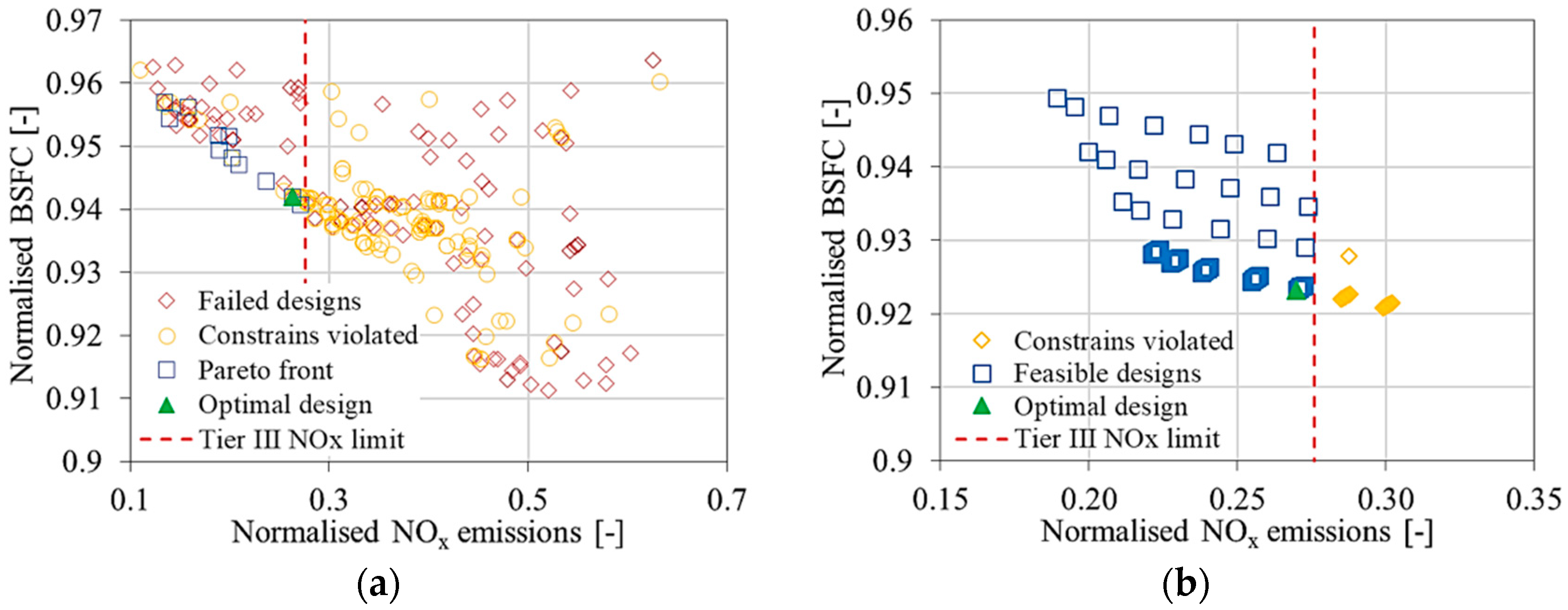
Figure 1. Engine layout with exhaust gas recirculation (EGR) and air bypass (ABP) systems.
Energies 13 05021 g001
Figure 2. Optimisation process flowchart.
Energies 13 05021 g002
Figure 3. Optimisation results of the engine parameters in the gas mode operation at 100% load (a) multiobjective genetic algorithm (MOGA) (case study 4) and (b) design of experiments (DoE) (case study 8).
Energies 13 05021 g003
Figure 4. Predicted engine parameters with EGR and ABP systems operation under steady state conditions (case studies 1–4 and 5–8).
Energies 13 05021 g004
Figure 5. Sensitivity analysis results.
Energies 13 05021 g005
Table 1. Engine main characteristics.
ParameterUnitValue
MCR power/speed/BMEPkW/r/min/bar8775/514/20
BSFC at MCR (diesel mode)g/kWh190
BSEC at MCR (gas mode)kJ/kWh7300
Bore/strokemm500/580
No. of cylinders/T/C units–/–9/1
Table 2. Single-Wiebe function parameters (diesel mode 100% load).
DescriptionUnitsParameter Value
Without EGRWith EGR 1
Start of combustion°CA 4.26.5
Main duration°CA5667
Main exponent/function shape factor 11
1 For 31% EGR rate at 100% engine load.
Table 3. Genetic algorithm settings.
ParameterValue
Population size40
Number of generations10
Crossover rate1
Crossover rate distribution index15
Mutation rateCalculated
Mutation rate distribution Index20
Random seedRandom
Table 4. Optimisation process parameters.
Optimisation PhaseLoad%255075100
Case Study ID 1234
MOGA OptimisationSettings (variables)EGR Blower speedr/min8500–9000
EGR valve openingdeg10–90
ABP valve openingdeg5–90
ConstrainsNOx emissions limitg/kWh2.583
EGR rate%30–40
T/C compressor surge marginfraction0.15–0.35
ObjectivesNOx emissionsg/kWhminimise
BSFCg/kWhminimise
EGR blower powerkWminimise
Case Study ID 5678
DoE OptimisationSettings (variables)Start of injection (SOI)°CA bTDC20–12
EGR valve openingdeg21–2333–3585–8790
ABP valve openingdeg6–850–5251–5349–55
ConstrainsNOx emissions limitg/kWh2.583
ObjectivesBSFCg/kWhminimise
NOx emissionsg/kWhminimise
Table 5. EGR and ABP systems optimisation results summary (case studies 1–4 and 5–8).
Optimisation PhaseLoad%255075100
Case Study ID 1234
MOGA OptimisationSettings (variables)EGR blower speedr/min9000900090009000
EGR valve openingdeg21338590
ABP valve openingdeg6505149
Output parametersNOx emissionsg/kWh2.622.572.492.46
BSFCg/kWh249.1221.3212.1214.9
EGR blower
power/PE
%0.761.171.822.32
Case Study ID 5678
DoE OptimisationSettings (variables)Start of injection (SOI)°CA bTDC−12−15−15−15
EGR valve openingdeg21338590
ABP valve openingdeg6505151
Output parametersBSFCg/kWh249.1220.7209.6210.6
NOx emissionsg/kWh2.622.412.592.52
EGR blower
power/PE
%0.761.141.782.32
ΔBSFC (BSFCwithout EGR - BSFCwith EGR)%8.410.29.910.2
ΔBSFC (BSFCwithout EGR - BSFCwith EGR and SOI)%8.49.98.88.4