Abstract
This paper presents a technical review of the existing pumped storage plants in Norway. The power system is changing towards integrating more and more renewable energy, especially from variable renewable energy sources, leading to new challenges for the security of supply, power, frequency, and voltage regulation. Thus, energy storage options are a highly researched topic in the current situation. Even though there are many energy storage technologies, most are optimal for short term grid balancing, and few are capable of providing long term (weekly or seasonal) storage. One exception is pumped storage, a mature technology capable of delivering both short term and long term energy storage. In this paper, the ten existing pumped storage plants in Norway are presented, several of which are capable of seasonal energy storage. The Norwegian knowledge and experience with pumped storage plants technology is provided as a basis for future research within the field. The review provides information about energy production and storage capabilities, construction costs, specific costs per kW and stored kWh, electromechanical installation, technical specifications, and operational experience with focus on the design of the tunnel system layout. The data presented in this review are unique and previously unpublished. A discussion and conclusions regarding the current situation, trends, and future outlook for pumped storage plants in Norway within the European power market are provided.
1. Introduction
Growing concerns regarding the climate change have led to a worldwide shift of focus from fossil fuels to renewable energy sources (RES) in order to reduce the environmental impacts of energy generation. In Europe, the goal of reducing greenhouse gas emissions is legislated through policy frameworks which set targets for energy consumption coming from renewable sources, starting in 1997, when the European Union (EU) set the 2010 targets. In 2018, under the “Clean energy for all Europeans” package, the EU set its 2030 targets on use of RES to at least 32% through the revised Renewable Energy Directive [1].
The main renewable energy sources constructed now are wind and solar, which are volatile and unregulated sources, where the fluctuations in energy production do not align with the fluctuations in energy demand. One way to eliminate this problem is to build many more wind and solar farms than necessary (backup power plants), in order to ensure that the energy demand is always covered. Another solution for eliminating the problem is energy storage, reducing the need for backup power plants. A very wide variety of energy storage technologies are currently available or under research, with the main ones being batteries, mechanical energy storage, hydrogen, and pumped hydro [2]. Batteries are a common solution for energy storage, having the advantage that they can be installed in any location, they have a quick energy release capability and a high round- trip efficiency varying between 70 and 95%, depending on the type of battery [3]. However, batteries can only store relatively small amounts of energy, making them a small-scale energy storage solution, suitable for power frequency and voltage regulation or hourly energy storage to help meet the peak demand. The lifetime of batteries is also limited compared with competing storage technologies. Mechanical energy storage is a technology using kinetic and gravitational energy to store energy. Compressed air energy storage (CAES) in the mechanical energy storage technology in which air is pumped in caverns or tanks during low energy demand periods. It is a mature technology, used for decades, cheap, and unlike batteries, it does not involve any use of toxic materials. The round-trip efficiency of CAES varies between 40 and 70% [4]. Disadvantages of CAES is that it requires a location with suitable geology, and moreover, the air needs to be heated during the energy generation, involving the use of fossil fuels in the diabatic method. Hydrogen energy storage is a technology in which electricity is converted into hydrogen through electrolysis, hydrogen is stored and later transformed back into electricity when the demand requires it. Despite a low round-trip efficiency of less than 50% [5], hydrogen energy storage has a high storing capacity comparing to all other energy storage technologies, being able to provide seasonal and annual energy storage, which led to an increased research interest into further developing it.
This paper focusses on the most mature and currently most applied electrical energy storage technology, pumped hydro. Pumped hydro stores energy in the form of water in a reservoir by pumping it during low demand periods and later releases it to produce energy, with the round-trip efficiency reaching above 80% depending on site-specific conditions [6]. Pumped hydro is able to provide seasonal energy storage [7,8], and is currently the world’s largest energy storage technology [9]. Currently, the technology is superior in both stored energy volumes and in power capacity. Further development is being researched, and underground pumped hydro is a promising new technology that may enable construction to be independent of topography and in combination with thermal storage, drinking water storage, or desalination [10]. To compare the costs of pumped hydro with competing technologies, this paper presents a calculation of constructions costs, specific costs per power capacity, and storage capacity. Previous studies have shown that pumped hydro has the lowest costs of currently existing storage technologies [11,12]. As can be seen from calculations presented in this paper, the Norwegian pumped storage plants (PSPs) have a low specific cost per kW and a very low specific cost per stored kWh compared to what is presented for other PSPs [7,10]. This is owing to beneficial topography that reduce the costs of storage reservoirs. A comparison of specific costs and a discussion of the trends for future development are presented in the discussion.
This main contribution in this paper is a technical review of the existing PSPs in Norway. The Norwegian power network is currently interconnected with Sweden, Denmark, the Netherlands, Russia, and Finland, and there are two more connections under construction, with Germany and the UK, respectively. The power grid is operated as a state-owned monopoly, but the majority of the power generation facilities are publicly owned. Moreover, Norway is currently the world’s sixth largest producer of renewable energy from hydropower, with approximately 125 TWh per year, according to the International Commission on Large Dams committee (ICOLD, Paris, France) [13]. The country has around 1600 hydropower plants (HPPs) producing about 95% of the total electricity in the national grid. Norwegian hydropower reservoirs hold approximately 50% of the total energy storage capacity in hydropower reservoirs in Europe [14]. However, only ten pumped storage plants (PSPs) exist with a total capacity of approximately 1400 MW. In this context, Norway has a large potential for expanding its pumped storage capacity and contribute with energy storage on a European scale.
Similar reviews have been published for the Austrian PSPs [15], and the US PSPs [16]. Previous reviews from Norway were published concerning the strategy for pumped storage plants [17,18] and about the cost and prospect potential by the Norwegian Water Resource and Energy Directorate (NVE) [19], but no technical review with descriptions of the existing PSPs has been published so far. Lia et al. [17] briefly presents the current state of PSPs in Norway and discusses the former and future strategies for PSPs development in Norway in the light of lack of national political solutions for power exchange on a European level, at the time. Ever since, progress has been done in the field, with two subsea cables are currently under construction, linking Norway with Germany (NordLink) and with UK (North Sea Link), with expected completion date in 2020 and 2021, respectively.
The current review covers the round-trip efficiency, construction costs, specific costs per kW and per stored kWh, tunnel system design, electromechanical installation, technical specifications, and operational experience. The review has a special focus on the design of the tunnel systems and how it influences the hydraulic transients. A discussion concerning the state-of-the-art for pumped storage plants and the future of pumped storage in Norway is provided.
Pumped Storage in Europe
Europe has the goal of becoming the first climate-neutral continent by 2050. In 2018, out of the 11,970 TWh gross energy consumption, 2270 TWh came from renewable energy sources [20]. The electricity generation from wind and solar power increased from 2% to 15% of the total electricity production from all sources between 2004 and 2018 [20]. Current research shows that the importance of energy storage increases significantly with the rise in variable renewable energy being included in the power system [21]. Currently, Europe had a total installed capacity of pumped hydro of 55 GW [22]. A total of 206 GW of long term energy storage with 30 TWh storage capacity is predicted to be installed in Europe in 2050, for the 89% renewable energy scenario [23]. For a 100% renewable energy Europe scenario, the storage need is estimated to range from 80 to 400 TWh, with installed capacity between 500 GW to 900 GW [24].
Austria, Switzerland, Norway, and Sweden have the largest available energy storage capacities in PSPs [25]. The countries with the highest pumped storage installed capacity are Italy (7685 MW), Germany (6364 MW), Spain (6117 MW), France (5837 MW), and Austria (5596 MW) [22]. Currently, Norway is 10th in Europe in terms of pumped storage installed capacity, with 1369 MW, leaving it with a high pumped hydro development capability, as Norwegian reservoirs equivalate nearly 87 TWh of energy storage [14], with 10–20 TWh of available capacity most of the time [26]. Previous studies showed the technical potential of developing additional capacity in terms of PSP without the need for constructing new reservoirs [27]. An estimation of the technical and economic potential in Austria yield that the country already exploited 75% of its hydropower potential, leaving it with 14 TWh maximum unexploited potential [28]. The Swiss Energy Strategy 2050 framework estimates an increase hydro capacity of 2 TWh, a target that can be reached only be finding hidden hydro potential [29]. In the case of Sweden, there is a 35 TWh expansion potential, currently limited due to environmental reasons, leaving it with a final potential of 6 TWh when taking into account the current technological development, which could eventually be increased with 2–4 TWh by upgrading current facilities [30]. The data about hydro potential in different counties shows that Norway has the largest unexploited storage capacity that can serve as support for further integration of the variable renewable energy sources into the European power system.
2. Historical Development of PSPs in Norway
The historical development of hydropower and PSPs in Norway is closely related with its industry development. All ten PSPs are located in the Central and West Norway (Figure 1). The first PSP in Norway is the 11 MW Brattingfoss power plant set in operation in 1955. This PSP was constructed for seasonal pumping in a hydropower scheme where the largest reservoir is on top of the scheme. Between 1962 and 1979, another five PSPs were built in Norway, with an installed capacity ranging from 35 MW to 270 MW.
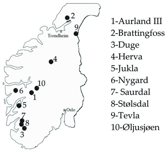
Figure 1.
Map of pumped storage plants (PSPs) in Norway.
The largest PSP is the 640 MW Saurdal PSP (320 MW pumping), set in operation in 1985, as part of the Ulla-Førre hydropower scheme. Included in the same scheme is also the smaller Stølsdal PSP, with an installed capacity of 17 MW. The Ulla-Førre hydropower scheme has a total installed capacity of 2100 MW, representing 6.4% of the total output in Norway. It supplies over 4.5 TWh annual energy production, representing 3.5% of the total Norwegian annual electrical energy consumption.
With the power market deregulation in 1991, a decrease in the development of large hydropower plants occurred in Norway. This is also observed in development of pumped storage plants, with only two pumped storage plants built in the new regime. Some new projects were licensed, but the construction start was postponed for an unknown period. One project, Illvatn pumped storage plant was recently licensed, with an expected output of 48 MW and 113 GWh per year [31]. The investment decision has currently not been taken.
The reason for the reduced hydropower and PSP construction after the deregulation is mainly that the market was saturated, and supply exceeded demand [32]. Before the deregulation, the power prices were mainly set in regional long term firm power contracts based on long term marginal cost for the producers. Combined with obligations for power producer to secure power supply in their specific region and limited flexibility in the market, this incentivized investments in overcapacity [32]. These are also explanations to why there has been few new PSPs constructed after the deregulation, and why most Norwegian PSPs are constructed for seasonal storage and why there are no short term PSPs. Another reason is that the Norwegian power system, based on hydropower with large reservoirs, has significant access to power and energy reserves, resulting in relatively low prices for system services such as frequency reserves.
3. Technical Review
This section presents a technical review of the ten existing PSPs in Norway. The data in this chapter are obtained from each PSP owner through questionnaires and interviews, in addition to original unpublished design reports, documentation, and construction or as-built drawings of the tunnel alignment, powerhouse, electromechanical units, and efficiency curves.
Norwegian PSPs are most commonly designed for seasonal storage. Due to the topography in Norway, with steep slopes and high plateaus, the larger reservoirs are located in the upper part of the catchment; thus, most PSPs are used to pump water to the upper reservoir during the snow-melting season, for storage to be used during the low-flow season. The common practice is to utilize natural existing lakes and increase the water level with dams for creating the storage volume. Tunnel systems connect the reservoirs to an underground powerhouse. It is common practice to have several brook intakes along the headrace and tailrace tunnels to collect water from smaller secondary water streams.
3.1. Overview of the Pumped Storage Plants
Table 1 presents an overview of the Norwegian PSPs. The ten PSPs have a cumulative capacity of 1369 MW. All schemes are open loop schemes with natural inflow and have in sum a gross energy production of 2.6 TWh per year. Considering the 0.8 TWh consumption for pumping, the PSPs have a net energy production of about 1.8 TWh per year.

Table 1.
PSPs in Norway.
Table 2 presents the energy storage capacities in the PSP reservoirs. The upper reservoirs are much larger compared with the downstream reservoir for all PSPs. This is due to the fact that most of the PSPs were designed for pumping of inflow during flood season and not pumping of the stored water in the downstream reservoir. The total storage capacity is over 5 TWh in the upper reservoirs and 0.85 TWh in the lower reservoirs. Two columns presenting the equivalent number of days of operation to empty or fill the reservoirs are presented. On average, it takes over 90 days with operation on full capacity to fill the upper reservoirs, and only 22 days to fill the lower reservoirs.
Table 2.
Energy storage in Norwegian PSPs.
3.2. Construction Costs and Specific Costs
The construction costs for each of the ten PSPs are estimated based on today’s prices to compare with other technologies and the individual PSPs. The Norwegian national cost base for hydropower has been applied to calculate the costs [33]. This cost base is regularly updated and is based on statistical construction costs for hydropower projects in Norway. Table 3 presents the estimated costs for the Norwegian PSPs. When compared with other published PSP costs, the Norwegian PSPs have a low specific cost per kW and a very low specific cost per stored kWh [7,10]. The specific cost per stored kWh is based on the energy storage capacity of the upper reservoir. This does not consider the limitation of the lower reservoir, but this is regarded as acceptable owing to the natural inflow to both upper and lower reservoir. Note that for comparison with other storage technologies and PSPs, these number do not reflect the fact that the Norwegian PSPs are open loop type with a significant net power production in addition. They also do not reflect the fact that most of these PSPs are located on top of a larger hydropower system and provide a significant value for the cascade of hydropower plants downstream.
Table 3.
Construction costs and specific costs.
The main reason for the large variation in specific cost is the role of each power plant, as most of these projects are included in larger hydropower schemes where the dams and tunnel systems benefit additional hydropower plants. As an example, the water pumped in Stølsdal PSP is to a large extent used for production in other HPPs located downstream in the scheme; thus, the energy production in Stølsdal specifically is very low. Its contribution to the total energy production of the hydropower scheme is not quantified in this paper owing to a large number of variables and uncertainties.
In Figure 2 it can be observed a correlation between the specific cost per kWh and the upper reservoir capacity, and head, respectively. The data included in the graphs are from nine of the PSPs. The data point from Stølsdal PSP is excluded due to the unnaturally high specific cost owing to the strategic placement in the larger scheme of hydropower plants, as explained above.
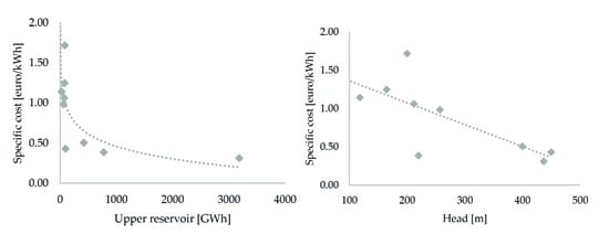
Figure 2.
Cost correlation analysis for the Norwegian PSPs.
The data show trends with decreasing specific cost with increasing upper reservoir capacity and head. This shows that optimal pumped storage plants are with high head and large upper reservoir, as could be expected. The decrease in specific costs seems to be logarithmic and converging with increasing reservoir capacity, and almost linearly decreasing with the increase of head. It can be noticed that the specific cost is almost halved when the head increases from 200 m to 400 m. At some point this trend must break of as it cannot continue to zero, but the breaking point cannot be found from our range of data.
3.3. Tunnel System and Hydrulic Transients
A schematic layout of a typical Norwegian PSP is presented in Figure 3. During turbining, water is transported from the upper reservoir to the turbine through the headrace tunnel and the penstock and continues to the lower reservoir though the tailrace tunnel. During pumping, it flows in reverse from lower reservoir to the upper reservoir. Along the tunnel various shafts can be observed, such as surge tanks and brook intakes. Surge tanks are constructed in order to reduce the pressure strain on the penstock from water hammer. Brook intakes (knows also as secondary intakes) are used to transport water from smaller catchments along the tunnel system, for an extra inflow. Commonly, these types of intakes are unregulated. The rock trap in Norwegian tunnels is normally located before the penstock, in order to protect the mechanical components from fallen rocks in unlined tunnels. Normally, a Norwegian PSP is located entirely underground, featuring D-shape tunnels constructed using the drill and blast method. Due to the good rock quality, lining is needed just along short sections where the tunnel crosses weakness zones, the rest of the tunnel being left unlined with local rock bolting and shotcrete where necessary (Figure 4).
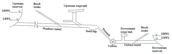
Figure 3.
Example of typical Norwegian PSP layout.
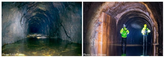
Figure 4.
Typical drill and blast tunnel in Norwegian PSPs: without lining (left) and with lined section (right).
A unique characteristic of Norwegian PSPs is the use and placement of rock traps in the tunnel systems. As previously mentioned, the hydropower tunnels are mainly unlined (Figure 4); thus, the risk of fallen rocks being transported to the turbine needs to be mitigated. In addition, in most cases, the road established in the tunnel during construction is not removed, therefore during power plant operation, parts of it erode and are flushed towards the turbines. In order to avoid damage to the penstock and the mechanical equipment, a rock trap and a fine trash rack are placed upstream the penstock, two examples being shown in Figure 5.
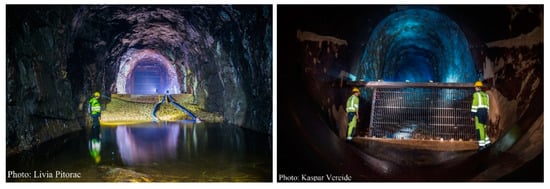
Figure 5.
Rock trap and trash rack: view from upstream (left) and view from downstream (right).
In most of the PSPs (Figure 6), there are also several brook intakes located along both the headrace and the tailrace tunnel. If the location of the brook intake is favorable, this is designed to function as a surge tank as well, otherwise, a separate surge tank is built, if necessary. The PSP tunnel systems in Norway are long, varying between 2 km and 17 km; thus, surge tanks are normally constructed in order to reduce the effect of the water hammer. As a consequence, mass oscillations occur in the system which result into the need for a well-analyzed design of the surge tank. In many projects, the preliminary design of the surge tank size is done using the Thoma stability criteria [34]. The design of the surge tank is a quite straightforward process if the surge tank is the only shaft in the system [35]. In Norway, the tunnel systems are often more complex with multiple brook intakes and unplugged adits along the main tunnels; thus, the design may require a more refined analysis. Commonly, the surge tank is a two-chamber surge tank type (Brattingfoss, Duge, Øljusjøen) or a shaft with upper expansion chamber (Herva, Nygard, Tevla). In one case, Jukla PSP, an underground closed surge tank filled with pressurized air is applied. Goodall et al. [36] and Vereide [37] present a more detailed description of closed surge tank design in Norway.
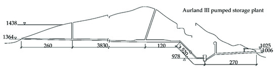
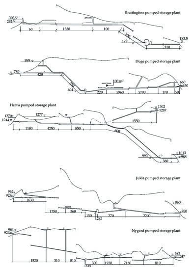
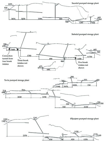
Figure 6.
The tunnel system layouts of the pumped storage plants in Norway.
3.4. Electromechnical Installation
An overview of the mechanical installation and electrical equipment in the Norwegian PSPs are shown in Table 4 and Table 5, respectively. Out of the ten PSPs in Norway, seven have reversible pump turbines (RPTs) and three have separate pump and turbine units. Generalized, there are five different start-up procedures for pumping mode:
Table 4.
Overview of mechanical equipment in Norwegian PSPs.
Table 5.
Overview of electrical equipment in Norwegian PSPs.
- In air with pony motor, soft-starter, or frequency converter.
- In water with electrical back-to-back start with a generator.
- In water with mechanical back-to-back start with a turbine.
- In water with frequency converter.
- Direct start.
For the first pump startup procedure, air is introduced in the pump with compressors, forcing the water out of the spiral casing. The units are then started in pumping mode with the pump rotating in air. The rotor is accelerated using a pony motor, soft starter, or frequency converter until the full speed of rotation is reached. When the speed of rotation is set to synchronous speed, air is released, water is admitted back inside the spiral casing, and the pump operation starts.
In the second procedure, the electrical back-to-back start, a pump unit is started using a nearby generator unit. With the two machines (generator and pump motor) being connected through the electrical system, both are excited with a current. The turbine runner starts to rotate; thus, the frequency increases, which triggers the motor to accelerate as well, until it synchronizes with the generator speed of rotation. When the motor reaches the synchronous speed of rotation, it is disconnected from the generator, the turbine unit is shut down, and the pumping commences.
The third start-up procedure, mechanical back-to-back start is implemented with a mechanical connection between the turbine and pump. This can be achieved in PSPs where the pump and the turbine runners are on the same shaft. In this procedure, first the turbine is started, accelerating the entire unit to the nominal speed of rotation. After the synchronization, the inlet valve of the turbine closes while the pump valve opens in parallel, and the pump operation starts.
The fourth start-up procedure is the most modern one, using frequency converters to start in water. With this technique, the units can be connected to the grid even if the unit is not at the synchronous RPM, resulting in a gentler starting with less momentum. Several variants exist such as full-size converters, part-size converters, transistor, and thyristor-based technology.
The fifth procedure, direct start is a brute connection of the pump motor to the grid from standstill. This method is the simplest and most traditional one, in which both the grid and the unit have to sustain a high start-up load, making it suitable just for small units, where both the grid and the machinery can withstand it. This procedure is characterized by high starting torque and full voltage and frequency from the beginning. In some cases, the pump starts with the main valves closed, and first opening when the normal operating pressure is reached.
Figure 7 shows the efficiency curves in turbine mode for ten of the installed turbines. The best efficiency point (BEP) of each turbine varies between 90.4% and 93.5%, and the power specific speed varies between 0.33 and 0.88 radians. The best efficiency point during pumping is known for 7 of the RPTs/pumps and it varies between 87.4% and 90.8%, with only two pumps having BEP under 88.2% and the other five having the BEP above 90.6%.
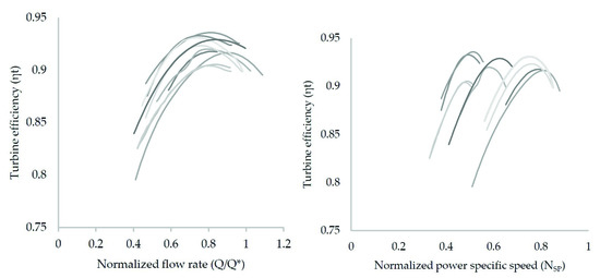
Figure 7.
Anonymized efficiency for a selection of the turbines in the described PSPs, function of unit flow (left) and function of power specific speed (right).
The round-trip efficiency for the ten PSPs varies between 65% and 80%. The waterway head loss in each PSP is calculated using an assumed Manning–Strickler number of M = 33 for the unlined tunnels, and M = 85 for the steel lined penstocks. The waterway is usually one of the main causes of energy losses ranging from less than 1% (Nygard) and up to 15% (Duge) depending on tunnel lengths. The round-trip electromechanical losses including the transformation in the range from 20% to 25%. The generator-motor and transformer efficiencies are assumed standard values of 98% and 99%. The real turbine and pump efficiencies as presented in the anonymized graphs above are used in the calculations. These calculations assume operation of full capacity, which is conservative as this generates the highest waterway head losses.
It is noted that all of the Norwegian PSPs are designed primarily for seasonal storage and pumping of water during the spring and autumn high flow seasons. Most of the power plants were not designed for frequent start–stop pump operations, which are reflected in the relatively time-consuming start-up procedures, varying between 6.5 min and few hours, in the case of old ones, and only going down to 2.3 min for the recently upgraded ones. The pump startup time is known for seven PSPs, out of which five have a startup below 10 min, meaning that they are be able to provide tertiary frequency reserves [38].
3.5. Particularities
Each of the ten PSPs have certain particular design features worth to mention. This section presents some of the most interesting from a hydraulic point of view. In the Brattingfoss PSP, the headrace tunnel crosses a steep valley, similar to a narrow canyon. In this area, an overground suspended pipe connects the upstream reservoir with the headrace tunnel as seen in Figure 8. Another feature of the Brattingfoss PSP is the design of the unit, which has both the pump and turbine runners connected to the same motor-generator on the same shaft. A horizontal sketch of the unit can be seen in Figure 9.
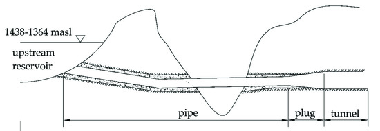
Figure 8.
Pipe section in Brattingfoss PSP.
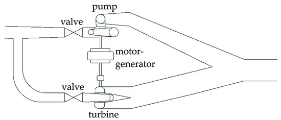
Figure 9.
Electromechanical layout plan view in Brattingfoss PSP, planar view.
The Duge PSP features a special intake design at the upstream reservoir. As shown in Figure 10, there is a higher and a lower intake. Both intakes can be used in turbine mode, while during pumping mode, only the upper intake is used. The reason for this is that the pump needs a minimum head in order to operate, which cannot be fulfilled when the water level in the upstream reservoir is low. In situations with low water levels, the gate of the lower intake is closed, and water is pumped only through the upper one, creating a waterfall down into the reservoir. Owing to the resulting energy loss, such situations occur very seldom. It can also be noted that the LRWL is below the lower intake, the reason being that the last volume of water can be released to power plants located downstream through bottom outlets, in case of severe draughts.
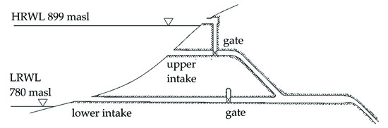
Figure 10.
Upstream intakes in Duge PSP.
The Herva PSP has two upstream reservoirs with different water levels; Hervavatn is regulated between 1302 and 1287 masl, and Storevatn is regulated between 1270 and 1244 masl. The reservoirs are used alternatively depending on the available reservoir volume. This gives a better flexibility in operation, and a larger total storage capacity.
The Jukla PSP has several interesting features. It has four upstream reservoirs: Juklavatn (1060 to 950 masl), Dravladalsvatn (957 to 880 masl), Jukladalsvatn (1083 to 990 masl) and Langavatn (962 to 927 masl). In addition, water from several brook intakes and transfer reservoirs is diverted to Dravladalsvatn using a series of diversion tunnels and channels. Downstream of the PSP, the water is diverted to two downstream reservoirs, Svartedalsvatn (860 to 834 masl) and Mysevatn (855 to 775 masl), which serve both as intake reservoirs for pumping mode and for a downstream power plant. Another particularity of Jukla PSP is the use of closed surge tank (Figure 11) for controlling the pressure transients. The closed surge tank has a total volume of 5500 m3, with an absolute pressure varying between 675 and 228 mWC, depending on which reservoirs are active [39]. Finally, owing to the large variation in water level between the different reservoirs, the generator has the possibility to short-circuit some of the poles to allow operation at either 500 RPM or 375 RPM.
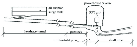
Figure 11.
Jukla air cushion surge tank and powerhouse detail.
The Nygard PSP is used to pump water from Stølsvatnet (584 to 547 masl) up to Skjerjavatnet (964 to 944 masl) during summer seasons and is used for power production during winter. While the PSP is part of the Modalen river, Skjerjavatnet is part of Eksingedalen river. Thus, in order to use Skjerjavatnet as an upstream reservoir, the original lake outlet was dammed, water being diverted through a tunnel to the PSP and further to Stølsvatnet in Modal river. In addition to the two reservoirs, water from eight brook intakes is used.
The Saurdal PSP is part of Ulla-Førre, the largest hydropower system in Norway, including Blåsjø, the largest reservoir in Norway, with about 8 TWh of energy storage, serving as upstream reservoir. Blåsjø was created by rising the levels in three natural lakes; Førrevatn, Oddatjern and Storvatn, which are located in two different river schemes. Saurdal has four units of 160 MW, whereof two of them are reversible pump turbines. Another characteristic to Saurdal is a U-tunnel section along the headrace tunnel (see Figure 12). As in the case of Brattingfoss, the headrace tunnel crosses a steep valley, but the solution in this case was the construction of a U-tunnel as seen in the figure. In addition, the upstream surge tank in Saurdal PSP is also used as a brook intake, with a maximum inflow of 2.1 m3/s. This makes Saurdal PSP a good example of using a brook intake as a surge tank in Norwegian PSPs.
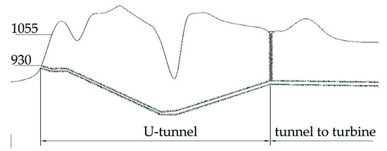
Figure 12.
U-tunnel in Saurdal PSP.
The Stølsdal PSP is smaller in terms of reservoir capacities, but it features 19 shafts along the headrace tunnel, mostly including brook intakes, and just one surge tank. The other 18 shafts are diverting water from 22 brook intakes to the headrace tunnel, out of which, four collect water from lakes with minor regulation. This makes the Stølsdal PSP the most complex PSP in Norway from the hydraulic point of view. The maximum total inflow in the 22 brook intakes with a mean cumulated discharge of 15 m3/s; considering that the maximum turbine capacity is 22 m3/s, during snow melting or rainfall, the water from the brook intakes cover over 70% of the turbine capacity. The General water level and necessary minimum head are controlled using two upstream reservoirs, Bjørndalsvatn (708 and 697 masl) and Sandsavatn (605 and 560 masl).
The Tevla PSP is used to prevent flood loss by pumping water to the upstream Fjergen reservoir during high inflow periods. The upstream reservoir has a larger storage capacity (204 mil. m³), as opposed to the downstream reservoir of just 4.5 mil. m³. Water from Fjergen is used for production in both the Tevla PSP and the downstream the Meråker HPP. The headrace tunnel in Tevla is a Y-tunnel, with one branch connecting the powerhouse to the upstream reservoir, having a cross section of 28 m2, and the second branch, with a cross section of 10 m2, transferring water from four brook intakes. In addition, on the first Y-branch, there is one more brook intake. The surge tank is located along the main headrace tunnel (28 m2).
The Øljusjøen PSP has initially been built for pumping the water in the upstream reservoir during flood periods, for further use in other downstream HPPs. Thus, water is pumped from a lower reservoir (Eldrevatn) and 16 brook intakes located along the tailrace tunnel system, to the upstream reservoir (Øljusjøane). Along the headrace tunnel system, there is just one brook intake, whose shaft is also used as a surge tank.
4. Operational Experience
The operators of the PSPs have been interviewed on operational experience as a follow-up for the technical questionnaires. During the interviews, each operator was asked about possible operational restrictions, rock falls, tunnel collapses, sand problems, problems or restrictions during tunnel dewatering, and measures taken to solve or prevent any encountered problem. Some specific topics of lessons learned are presented in this section.
Aurland III PSP has in 2016–2017 been upgraded with new starting mechanism for pumping mode [40]. Previously, this PSP had a direct start with half of the nominal voltage provided by two coupling windings in the transformer that resulted in a high strain of the electromechanical equipment. Now, a frequency converter is installed, reducing the strain on the machinery during start-up. The drawback that Aurland III encounters is that in pumping mode, the units are not started both at the same time, a company decision in order to avoid the risk of failure. A frequency converter or soft starter investment is considered for the Duge PSP as well [40].
Three of the ten PSPs have reported tunnel collapses. The Duge PSP experienced a tunnel collapse in the 12 km long tailrace tunnel shortly after the first water filling. The tailrace tunnel is mainly unlined, and the collapse occurred in a weakness zone of which the strength was overestimated. The Saurdal PSP experienced a tunnel collapse in the tailrace tunnel after several years of operation. Recently, a major tunnel collapse was discovered also along the headrace tunnel of the Saurdal PSP, which could not be cleaned due to safety reasons; thus, construction of a by-pass tunnel is currently under investigation. Finally, the Stølsdal PSP reported a tunnel collapse in one of the brook intakes. At Duge PSP, the main reason for the tunnel collapse was not the fact that it was a PSP, as the collapse occurred shortly after commissioning. For the two other PSPs one may speculate that the operation as a PSPs might have increased the stresses of the rock mass surrounding the tunnels and might have influenced the collapse.
The Duge PSP has reported a problem of rotor lifting, where the rotor of the unit is lifted of its bearings when operated at too high load. This situation started after a refurbishment of the units in 2017. The reason is the very high submergence of the units (more than 40 m) combined with a long tailrace tunnel (12 km) that results in a high pressure from downstream on the turbine. The power plant is currently operating with a restriction of maximum 80% of installed capacity. Measures to repair the units and return to normal operation are currently undertaken.
The Duge PSP has a very long tailrace tunnel. To dewater and inspect the tunnel, over 600,000 m3 of water has to be pumped more than 50 m in vertical elevation out of the tunnel. This is very costly and has only been done once in the power plants lifetime (after the tunnel collapse). Recently, a tunnel inspection of the 12 km long tailrace tunnel in Duge was successfully conducted with a remotely operate vehicle (ROV). The tunnel inspection took less than 24 h and could be conducted without dewatering the tunnel. The ROV was used to scan and film the inside of the unlined tunnel to document the current condition after 50 years of operation. The condition was found to be good with only minor and insignificant rock fall.
The Duge PSP currently experiences problems with sand and debris clogging filters and seals in the turbine during pumping mode. This problem started after a change of downstream water level restriction for pumping mode. Previously, pumping was not allowed below 655 masl in the lower reservoir. In the last years, this restriction has been changed to 650 masl. It is likely that during the 40-year lifetime of this power plant, sand and debris has deposited in the lower reservoir close to the intake and is now being sucked back into the tunnel during pumping on lower reservoir levels.
The Herva PSP reported limitations due to the design of the electro-mechanical equipment. The unit consists of separate pump and turbine runners, connected to the same motor-generator machine; the pump runner only being connected to the unit when running in pumping mode. Due to a time-consuming coupling procedure of the pump runner, the pump is only operated once a year, for a few weeks during flood season. During pump operation, the turbine runner is still coupled to the motor-generator; thus, in order to reduce the friction losses, the water is evacuated from the turbine spiral case. Such limitations would make it impossible for the Herva PSP to be used for primary frequency control or secondary frequency control unless the pump runner is kept connected all the time.
5. Discussion
The Norwegian power system is almost entirely based on hydropower plants with storage reservoirs, with very small percent of variable energy sources, resulting in a robust power system with sufficient energy storage and frequency reserves. As a result, all ten pumped storage plants in Norway were not designed for system services or daily peak demand, but for pumping water during flood season, in order to store it for the high demand periods. Another reason for the PSPs to be designed for capturing the flood water is that in Norway, due to the topography, the larger reservoirs are mainly located on plateaus on the top of the catchments. The Stølsdal, Nygard, and Duge PSPs have the upper reservoir twice the size of the lower reservoir. For Aurland III and Tevla PSPs, the proportion between the two reservoirs is around 1 to 45. This demonstrates that the main purpose of the pumping in most of the schemes is to pump inflow and not water stored in the downstream reservoir. However, most of the schemes have sufficient size of the lower reservoir to also allow daily and weekly pumping of stored water to profit from variations in the power prices.
The specific costs per kW is low and the specific cost per stored kWh is very low when compared with published number for PSPs in other countries [7,10]. This can be explained by the Norwegian topography, which enables efficient construction of reservoirs with large volumes at high elevations. For construction of new PSPs in Norway, the costs can be expected to be even lower, as these can be constructed between already existing hydropower reservoirs. The costs can be further reduced by upgrading existing hydropower plants and utilizing the existing tunnel systems. The costs will then be reduced to only the pumping units and powerhouse expansion. The total existing available hydropower storage in Norway is currently about 85 TWh. Previous studies have identified potential to construct over 60,000 MW of pumped storage in Norway [18].
The technical review shows that there is currently only 1369 MW installed capacity in PSPs in Norway. All PSPs have a head between 103 m and 465 m, placing them in high head hydropower plant category. Five out of these are large PSP, having an installed capacity above 50 MW, and the others are medium PSPs. There is no small PSP (below 10 MW), this being because they were designed to work as support for various industrial factories around the country, which needed a large, rather constant power supply. When looking into the power production versus the power consumption of each PSP, it is observed that the net power production is positive in all cases. This is consistent with the fact that all PSPs are open loop schemes, meaning that the water used for generation comes both from pumping and from the catchment in which the PSP is located.
The typical Norwegian PSPs has three special design characteristics, comparing with PSP in other parts of the world. First, the tunnels are commonly constructed using the drill and blast method and are left unlined after commissioning, this being possible due to the good rock quality in the Scandinavian mountain range. Even if unlined tunnels have a higher tunnel roughness than lined tunnels, which leads to an increase in the major head loss, by not lining the tunnels, the cross section is larger, compensating for the influence of the roughness. This design is applied for all ten PSPs presented in this paper. Second, a rock trap solution is normally located inside the tunnel, upstream the penstock or downstream the draft tube. Since erosion in the Norwegian rivers is usually relatively small, a sand trap at the intake upstream the tunnel is not necessary. On the other hand, leaving the tunnels unlined could lead to rock falls which, if not trapped, can be transported to the turbine and damage it. Another possible source of debris that needs to be trapped is pieces of eroded road. Typically, for facilitating transport within the tunnel during construction, inspection, or maintenance, a road is built in the tunnel, parts of which can be eroded and transported to the turbine. In order to prevent any damage by rock falls or eroded road parts, a rock trap is placed within the tunnel. For this reason, a rock trap is located upstream the penstock or downstream the draft tube, respectively. The third design characteristic of Norwegian PSPs is the typical high number of brook intakes. Due to the topography, Norwegian hydropower tunnels are long, crossing under many small secondary streams. For this reason, along the tunnels there are several brook intakes capturing the water from the secondary streams and bringing to the system. Along the headrace tunnel of the PSPs in Norway, there are on average between zero and three brook intakes, except for Tevla PSP and Stølsdal PSP, which have 6 and 10 brook intakes, respectively. Both Tevla and Stølsdal PSP have side tunnels with the only scope of connecting brook intakes to the main headrace tunnel. Interesting is the fact that water is brought to the system through brook intakes along the tailrace tunnel as well, in the case of PSPs, as opposed to HPPs. It can be noticed that there is no correlation between the size of the PSP and the number of brook intakes. No correlation between the size of the reservoirs and number of brook intakes could be observed either.
The most common unit used in Norwegian PSPs is the reversible pump turbine, found in seven of the plants (Aurland III, Duge, Jukla, Nygard, Saurdal, Tevla, and Øljusjøen). The start-up procedure for pumping is varied, but a common feature of most PSPs is that the pump is started in air. All of the PSPs were designed for seasonal pumping during high flow periods during spring and autumn. The majority of the PSPs therefore have time-consuming starting mechanisms to reduce costs and electromechanical strain on the units. The operation of the pumps is still primarily for seasonal storage during periods with high inflow. However, more frequent start–stops and operation also during low flow periods can be observed. It is therefore becoming more attractive for the PSP owners to upgrade the starting mechanism for enabling more frequent and rapid start–stop operations.
6. Conclusions
There currently exist 1369 MW installed capacity with an energy storage capacity of about 5 TWh in the ten existing PSPs in Norway. The construction costs have been calculated with current prices based on a national cost base with price statistics for hydropower in Norway. The results show that the specific costs per kW is low and the specific cost per storage kWh is very low compared with published numbers from PSPs in other countries. There is a large potential for construction of new PSPs in Norway. The costs of new PSPs can be even lower as they can be constructed between existing reservoirs and by upgrading already existing hydropower plants into PSPs.
The round-trip efficiencies range from 65% to 80% for the ten PSPs. Most of the PSPs in Norway have long tunnel systems, which is one of the main causes of energy loss. The round-trip energy loss from the tunnel system ranges from less than 1% (Nygard) to 15% (Duge). The round-trip electromechanical losses including the transformer range from 20% to 25%. It is noted that the electromechanical efficiencies may be improved by upgrading the units, while the tunnel system head loss is usually not feasible to reduce.
All the Norwegian PSPs are open loop, with significant natural inflow to the reservoirs. This results in operation primarily as a normal hydropower plant with shorter periods of pumping. The PSPs have a significantly higher energy production compared with energy consumption. The operation of the Norwegian PSPs is still mainly for seasonal pumping, but a shift towards more frequent start–stop operation can be observed. Pumping during nighttime and no operation during daytime is becoming more frequent.
In general, the Norwegian PSPs have time-consuming pump starting mechanisms, being designed for seasonal storage. However, it is possible to upgrade the starting mechanism as it was done in Aurland III PSP in 2016–2017. Such upgrading is becoming more attractive when the spread between high and low power prices is increasing, and system services are priced higher.
Tunnel collapses have occurred in three out of ten PSPs. Two of them occurred after several years of operation and may be related to the additional strain of pumping operation compared to normal hydropower plants. The variation of the pressure on the rock mass around the tunnel is significantly higher in PSPs as opposed to HPPs; thus, this needs to be accounted for during design of tunnel systems.
The hydraulic system of each PSP in Norway is unique and with many interesting features. Several technical solutions can still be regarded as innovative and the operational experience is worthwhile to share with the research community.
Author Contributions
Conceptualization, L.P., K.V., and L.L.; data collection, L.P. and K.V.; data analysis, L.P.; writing—original draft preparation, L.P. and K.V.; writing—review and editing, K.V. and L.L.; supervision, K.V. and L.L.; project administration, L.L.; and funding acquisition, K.V. and L.L. All authors have read and agreed to the published version of the manuscript.
Funding
This research is financed by and conducted as a part of the Norwegian Research Center for Hydropower Technology (HydroCen).
Acknowledgments
The data is provided by the power plant owner and operators: Statkraft Energi, Sira-Kvina kraftselskap, E-CO Energi, Nord-Trøndelag Elektrisitetsverk, BKK Produksjon, Hydro Energi, Østfold Energi
Conflicts of Interest
The authors declare no conflict of interest.
References
- Directive (EU) 2018/2001 of the European Parliament and of the council of 11 December 2018 on the promotion of the use of energy from renewable sources. Off. J. Eur. Union 2018, OJ L 328, 1–128.
- Schaber, C.; Mazza, P.; Hammerschlag, R. Utility-scale storage of renewable energy. Electr. J. 2004, 17, 21–29. [Google Scholar] [CrossRef]
- Moseley, P.T.; Garche, J.; Elsevier, B. Electrochemical Energy Storage for Renewable Sources and Grid Balancing; Elsevier B.V: Amsterdam, The Netherlands, 2015. [Google Scholar]
- Abdin, Z.; Khalilpour, K. Chapter 4-Single and polystorage technologies for renewable-based hybrid energy systems. In Polygeneration with Polystorage for Chemical and Energy Hubs; Academic Press: Cambridge, MA, USA, 2018; pp. 77–131. [Google Scholar]
- Steilen, M.; Jorissen, L. Chapter 10-hydrogen conversion into electricity and thermal energy by fuel cells: Use of H2-systems and batteries. In Electrochemical Energy Storage for Renewable Sources and Grid Balancing; Elsevier: Amsterdam, The Netherlands, 2015. [Google Scholar]
- Kumar, A.; Schei, T.; Ahenkorah, A.; Caceres Rodriguez, R.; Devernay, J.M.; Freitas, M.; Hall, D.; Killingtveit, Å.; Liu, Z. Hydropower. In IPCC Special Report on Renewable Energy Sources and Climate Change; Cambridge University Press: Cambridge, MA, USA, 2011; pp. 437–496. [Google Scholar]
- Deane, J.; Gallachóir, B.O.; McKeogh, E. Technico-economic review of existing and new pumped hydro energy storage plant. Renew. Sustain. Energy Rev. 2010, 14, 1293–1302. [Google Scholar] [CrossRef]
- Hunt, J.D.; Byers, E.; Wada, Y.; Parkinson, S.; Gernaat, D.E.H.J.; Langan, S.; van Vuuren, D.P.; Riahi, K. Global resource potential of seasonal pumped hydropower storage for energy and water storage. Nat. Commun. 2020, 11, 947. [Google Scholar] [CrossRef] [PubMed]
- Rogner, M.; Troja, N. The World’s Water Battery: Pumped Hydropower Storage And Clean Energy Transition; IHA: London, UK, 2018. [Google Scholar]
- Pikl, F.G.; Richter, W.; Zenz, G. Large-scale, economic and efficient underground eneegy storage. Geomech. Tunn. 2019, 12, 251–269. [Google Scholar] [CrossRef]
- Pumped Energy Storage: Vital to California’s Renewable Energy Future; San Diego County Water Authority: San Diego, CA, USA, 2019.
- Schmidt, O.; Melchior, S.; Hawkes, A.; Staffell, I. Projecting the future levelized cost of electricity storage technologies. Joule 2019, 3, 81–100. [Google Scholar] [CrossRef]
- ICOLD Committee on Dams for Hydroelectric Energy. Bulletin 163: Dams for Hydroelectric Energy; International Commission on Large Dams (ICOLD): Paris, France, 2017. [Google Scholar]
- Hydro in Europe: Powering Renewables; Eurelectric: Brussels, Belgium, 2011.
- Pumped Storage Hydropower in Austria; Technischen Universität Graz: Graz, Austria, 2018.
- Compendium of Pumped Storage Plants in the United States; American Society of Civil Engineers: New York, NY, USA, 1993.
- Lia, L.; Vereide, K.; Strypet, L.F.; Kvaal, B. The new strategy for PSP in Norway-medium sized projects in existing power schemes. In Proceedings of the Hydro 2016 Conference, Montreux, Switzerland, 10–12 October 2016; Aqua-Media International Ltd.: Sutton, UK, 2016. [Google Scholar]
- Charmasson, J.; Belsnes, M.; Andersen, O.; Eloranta, A.; Graabak, I.; Korpås, M.; Helland, I.P.; Sundt, H.; Wolfgang, O. Roadmap for Large-Scale Balancing and Energy Storage from Norwegian Hydropower. Opportunities, Challenges and Needs Until 2050; CEDREN: Trondheim, Norway, 2017. [Google Scholar]
- Pumpekraft i Norge; The Norwegian Water Resources and Energy Directorate (NVE): Oslo, Norway, 2011.
- Eurostat. European Office of Statistics. Available online: https://ec.europa.eu/eurostat/ (accessed on 15 July 2020).
- Scholz, Y.; Gils, H.C.; Pietzcker, R. Application of a high-detail energy system model to derive power sector characteristics at high wind and solar shares. Energy Econ. 2017, 64, 568–582. [Google Scholar] [CrossRef]
- International Hydropower Association. Hydropower Status Report. Sector trends and Insights; IHA: London, UK, 2020. [Google Scholar]
- Cebulla, F.; Naegler, T.; Pohl, M. Electrical energy storage in highly renewable European energy systems: Capacity requirements, spatial distribution, and storage dispatch. J. Energy Storage 2017, 14, 211–223. [Google Scholar] [CrossRef]
- Droste-Franke, B.; Carrier, M.; Kaiser, M.; Schreurs, M.; Weber, C.; Ziesemer, T. Improving Energy Decisions Towards Better Scientific Policy Advice for a Safe and Secure Future Energy System; Springer: Berlin, Germany, 2015. [Google Scholar]
- Heide, D.; Greuner, M.; von Bremen, L.; Hoffmann, C. Reduced storage and balancing needs in a fully renewable European power system with excess wind and solar power generation. Renew. Energy 2011, 36, 2515–2523. [Google Scholar] [CrossRef]
- The Norwegian Water Resources and Energy Directorate (NVE). Norway and the European Power Market. Available online: https://www.nve.no/norwegian-energy-regulatory-authority/wholesale-market/norway-and-the-european-power-market/ (accessed on 15 July 2020).
- Solvang, E.; Charmasson, J.; Sauterleute, J.; Harby, A.; Killingtveit, Å.; Egeland, H.; Andersen, O.; Ruud, A.; Aas, Ø. Norwegian Hydropower for Large-Scale Electricity Balancing Needs; SINTEF Energy Research: Trondheim, Norway, 2014. [Google Scholar]
- Harreiter, H. Empowering Austria: The electricity strategy of Austrian electricity companies. Wasserwirtschaft 2017, 107, 23–27. [Google Scholar] [CrossRef]
- Müller, A.; Münch-Alligné, C.; Nicolet, C.; Denis, V.; Avellan, F. Pushing the envelope: Switzerland’s approach to unlocking hidden hydropower potential. In Hydro; Hydropower and Dams: Porto, Portugal, 2019. [Google Scholar]
- Byman, K. Future Electricity Production in Sweden; The Royal Swedish Academy of Engineering Sciences (IVA): Stockholm, Sweden, 2016. [Google Scholar]
- Hydro. Illvatn pumpekraftverk Luster kommune. Konsesjonssøknad med konsekvensutredning; Norges Vassdrags-og Energidirektorat: Oslo, Norway, 2010. [Google Scholar]
- Bye, T.; Hope, E. Deregulation of electricity markets-The Norwegian experience. Econ. Pol. 2005, 40, 5269–5278. [Google Scholar]
- Kostnadsgrunnlag for Vannkraft (Cost Base for Hydropower Plants). Norwegian Water Resources and Energy Directorate; The Norwegian Water Resources and Energy Directorate (NVE): Oslo, Norway, 2016. [Google Scholar]
- Thoma, D. Zur Theorie des Wasserschlosses bei Selbsttätig geregelten Turbinenanlagen; Walter De Gruyter: Munchen, Germany, 1910. [Google Scholar]
- Anderson, A. Surge shaft stability with pumped-storage schemes. J. Hydraul. Eng. 1984, 110, 687–706. [Google Scholar] [CrossRef]
- Goodall, D.; Kjørholt, H.; Tekle, T.; Broch, E. Air cushion surge chambers for underground power plants. Int. Water Power Dam Constr. 1988, 11, 29–34. [Google Scholar]
- Vereide, K. Hydraulics and Thermodynamics of Closed Surge Tank for Hydropower Plants; Norwegian University of Science and Technology (NTNU): Trondheim, Norway, 2016. [Google Scholar]
- Network Code on Load-Frequency Control and Reserves; ENTSO-E: Brussels, Belgium, 2013.
- Vereide, K.; Tekle, T.; Nilsen, T.K. Thermodynamic behavior and heat transfer in closed surge tanks for hydropower plants. J. Hydraul. Eng. 2015, 141, 06015002. [Google Scholar] [CrossRef]
- Breiland, S. Reconstruction of the Pumped Hydropower Plant, Duge; University of South-Eastern Norway: Notodden, Norway, 2019. [Google Scholar]


© 2020 by the authors. Licensee MDPI, Basel, Switzerland. This article is an open access article distributed under the terms and conditions of the Creative Commons Attribution (CC BY) license (http://creativecommons.org/licenses/by/4.0/).