Article

Virtual Pressure Sensor for Electronic Expansion Valve Control in a Vapor Compression Refrigeration System

1
Oak Ridge National Laboratory, Oak Ridge, TN 37830, USA
2
UTC—Carrier Corporation, Charlotte NC 28269, USA
*
Author to whom correspondence should be addressed.
Energies 2020, 13(18), 4917; https://doi.org/10.3390/en13184917
Submission received: 21 August 2020 / Revised: 13 September 2020 / Accepted: 17 September 2020 / Published: 19 September 2020
(This article belongs to the Special Issue Heat Transfer, Refrigeration and Heat Pumps)

Abstract

:
Virtual sensor technology, which uses simulation models/algorithms to calculate a value to represent an unmeasured variable or replace a directly measured reading, has attracted many studies in the heating, ventilation, air conditioning and refrigeration (HVAC&R) industry. However, most virtual sensor technologies are developed for fault detection and diagnostics (FDD) purposes, which generally compare the virtual sensor values with actual measured values to detect if any fault occurred and identify the causes that led to the fault. It is rare to see studies focus on control performance of virtual sensors after substituting an actual sensor. This is particularly important for the system with no redundant sensor since a virtual sensor is the most effective way to operate the system in the desirable region when any sensor failure occurs. To address this gap, this paper develops a new virtual pressure sensor technology to substitute the actual pressure measurement for electronic expansion valve (EXV) control in a vapor compression refrigeration system by integrating compressor and valve characteristics. The control performance of this proposed virtual pressure sensor technology under various operating conditions is validated with experimental data. Closed loop EXV control simulations with the proposed virtual pressure sensor are conducted, and the results are analyzed.

1. Introduction

Superheat control is critical for refrigeration systems to prevent compressor flooding while maintaining system capacity and efficiency. In general, two types of control devices are widely used: thermal expansion valves (TXVs) and electric expansion valves (EXVs). Due to the superior control characteristics, EXVs have become more popular in the refrigeration industry. Using the EXV technology to control system superheating requires both temperature and pressure sensors to be installed on the system. In the situation of a pressure transducer malfunctioning, which is not unusual, maintaining a proper superheat conditions becomes difficult and very crucial for system operation. If there is no redundant pressure transducer installed, the superheat temperature cannot be calculated directly based on the malfunctioning pressure sensor. An alternative approach is to use the estimated pressure, called virtual pressure, to calculate the superheat condition to supporting the EXV control.
Virtual sensor technology, which uses simulation models/algorithms to process what a physical sensor otherwise would, has attracted many studies in the heating, ventilation, air conditioning and refrigeration (HVAC&R) industry due to several significant advantages, such as cost effectiveness, easy maintenance and lack of constraints by the environment or operating condition. Andiroglu et al. [1] developed a virtual pump water flow sensor using either the variable frequency drive input power or motor input power with a calibrated pump, motor and variable frequency drive efficiencies along with the consideration of additional harmonic energy loss. Eric et al. [2] presented a low cost, practical and non-intrusive virtual flow meter to estimate the chilled and condenser water mass flow rate using data from a building automation system. The virtual flow meter is used in fault detection and diagnostics (FDD) of the cooling plant coefficient of performance (COP). Christian et al. [3] developed a virtual flow sensor using a model, measurements of boundary conditions and an EXV control signal. Compared to other studies which focus on the single-phase inlet conditions, Christian et al.’s virtual flow sensor can be used for both two-phase and subcooled valve inlet conditions through continuous correction. Virtual pressure sensors [4] were developed for estimating compressor discharge line pressure, condensing pressure, liquid line pressure, evaporating pressure and suction line pressure for the purpose of FDD. Several virtual refrigerant charge sensors [5,6,7] were developed to evaluate the refrigerant charge level of different types of vapor compressor systems, such as those with/without an accumulator and fixed/variable speed compressors. Zhao et al. [8] used commonly available onboard chiller measurements to develop a virtual chiller condenser fouling sensor to monitor the condenser fouling status for the purpose of chiller FDD. Li et al. [9] described a virtual compressor power consumption sensor based on a 10-coefficient polynomial equation and virtual refrigerant flow sensor calculated through a compressor volumetric efficiency prediction. Hjortland et al. [10] developed virtual sensors for supply air flow rate and indoor fan power used for rooftop unit air-side diagnostics based on indoor fan differential pressure and speed measurements. Recently, virtual in situ sensor calibration (VIC) and sensor fault detection and diagnostics (SFDD) have been developed for the continuous correction of building system operation [11,12].
Almost all these virtual sensor technologies were developed for FDD purposes, which generally compare the virtual sensor values with actual measured values to identify if any fault occurred and the causes that led to the fault. It is rare for research to focus directly on replacing the actual sensor with the virtual sensor through integrating the virtual sensor into the control system and evaluating the impact of the virtual sensor on the control performance. This is particularly important for the system with no redundant sensors since a virtual sensor is the most effective way to operate the system in the desirable region when any sensor failure occurs. To address this issue, this study develops a new virtual pressure sensor technology to substitute the actual pressure measurement in the EXV control of a refrigeration system. The control performance of using this proposed virtual pressure sensor technology under various operating conditions is also investigated.

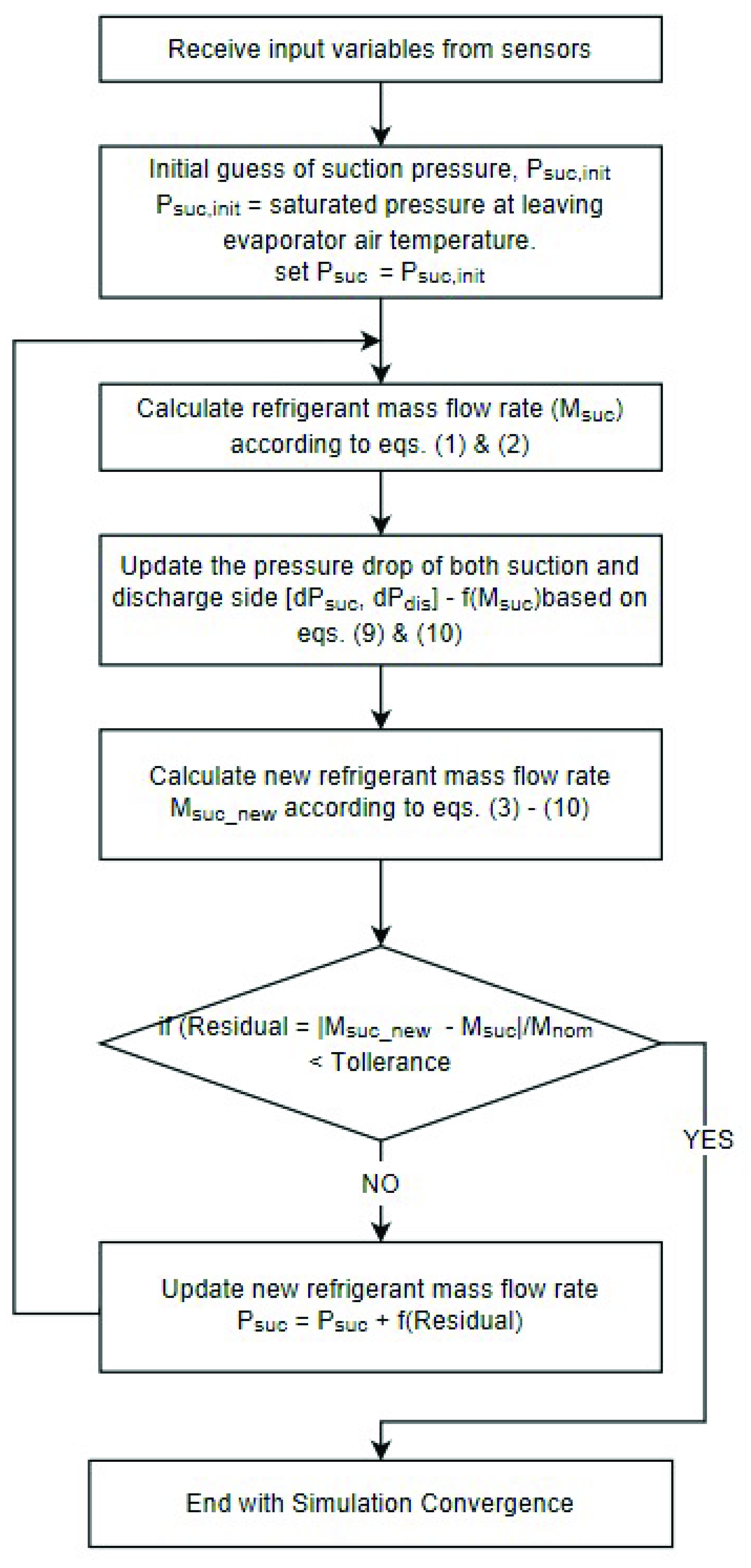
2. Mathematic Model of Virtual Pressure Sensor

In a typical vapor compression refrigeration system, the EXV adjusts the refrigerant volume across the EXV to maintain a desired superheat temperature at the outlet of the evaporator. The compressor is to transport a certain volume of refrigerant from a certain state (suction) to another state (discharge). The refrigerant volume through the EXV and compressor is balanced based on the EXV and compressor operation characteristics (Figure 1), which can be formulated to predict the suction pressure or evaporator superheat temperature under various operating conditions.
The following assumptions are used for simplifying the theoretical identification of the independent variables which influence the pressure prediction.
  • The refrigerant suction side pressure loss through the evaporator is a function of mass flow rate.
  • The refrigerant discharge side pressure loss through the condenser and economized heat exchanger is a function of mass flow rate.
  • The energy loss when the refrigerant passes through the expansion valve is negligible.
  • It should be noted that the approaches discussed in this paper assume the refrigerant does not have a varying saturation temperature for a specific pressure (generally referred to as “glide”).
  • The condenser fan is at a constant speed.
  • The physical sensors for inputs of this model are assumed to be fault free.
According compressor characteristics, the compressor suction side mass flow is
m = ρ s u c V s u c
The suction volumetric flow rate Vsuc can be estimated by [13]
V s u c = { 1 C 0 [ ( P d P s ) 1 γ 1 ] } N c o m p V d i s p
where C0 is a constant, γ is an isentropic exponent and a constant for a specific refrigerant, Pd is compressor discharge side refrigerant pressure, Ps is compressor suction side refrigerant pressure, Ncomp is compressor speed and Vdisp is compressor displacement volume.
According to EXV throttling characteristics [14], the refrigerant mass flow crossing the EXV is
m = C e x v A e x v 2 ρ i n ( P i n P o u t ) = C e x v A e x v 2 ( 1 P i n P o u t )   ρ i n P i n
where Aexv is valve throat area, Cexv is flow coefficient, ρin is EXV inlet refrigerant density, Pin is EXV inlet refrigerant pressure and Pout is EXV outlet refrigerant pressure.
A correction factor, CF, is introduced to rewrite the above equation as
m e x v = C F ρ i n P i n
where
C F = C e x v A e x v 2 ( 1 P i n P o u t )
A polynomial function is developed to calculate the correction factor
C F = C 1 + C 2 E x v % + C 3 E x v % 2
where C1, C2, C3 are constants and Exv% is expansive valve opening position as a percentage.
The refrigerant density at compressor suction ρsuc and EXV inlet ρin in Equations (1) and (4) can be evaluated through refrigerant property calculation functions
ρ s u c = R e f ( P s ,   T s u c )
ρ i n = R e f ( P i n ,   T i n )
where Ps, Tsuc are the pressure and temperature at the compressor suction port and Pin, Tin are the EXV inlet pressure and temperature.
The relationships between Ps and Pout, Pd and Pin are given by
d P s u c = d P s u c _ n o r m ( m / m n o r m ) 2
d P d i s = d P d i s _ n o r m ( m / m n o r m ) 2
where dPsuc_norm, dPdis_norm are the normalized pressure loss of suction side and discharge side and mnorm is the normalized refrigerant mass flow rate.
Substitute Equations (6)−(10) into Equation (5) to receive
R e f ( P s , T s u c ) × { 1 C 0 [ ( P d P s ) 1 γ 1 ] } N c o m p V d i s p   = ( C 1 + C 2 E x v % + C 3 E x v % 2 ) × 2 R e f ( P d d P d i s , T i n ) ( P d P s d P s u c d P d i s )
In Equation (11), C0, … C6, dPsuc, dPdis are constants and can be curve fitted with experimental or manufactured test data. Tsuc, Pd, Tin are measurable variables, Exv% is the control signal and the only unknown variable is Ps. Thus, solving Equation (11) results in a predicted suction pressure value, then a superheat temperature value with the leaving evaporator temperature measurement. The flow chart shown in Figure 2 describes the algorithm.
As shown in Figure 2, the virtual pressure sensor module receives sensor inputs per each time step. An initial guess of compressor suction pressure is given as the saturated pressure at the evaporator supply air temperature. The refrigerant mass flow rate can be calculated by compressor characteristics as in Equations (1) and (2). The pressure loss of both the suction side and discharge side can be calculated with Equations (9) and (10). Then a new refrigerant mass flow rate is given by solving Equations (4)–(6). The difference between these two calculated refrigerant mass flow rates is checked with a predefined convergence tolerance. If the simulation does not converge, the compressor suction pressure is updated with a new value to repeat the above steps, otherwise the calculated compressor suction pressure is the solution.

3. Model Calibration and Validation

The steady-state testing data from a typical vapor compression refrigeration system are used to calibrate the proposed virtual pressure sensor model method to identify the model parameters and evaluate its performance. These testing data cover a wide range of operation conditions: the ambient temperature can vary from 50 °C to −25 °C, and the refrigerated space can be set at any temperature between 30 °C and −20 °C. The calibrated model parameters are listed in Table 1. The tested compressor temperature and pressure (suction and discharge), mass flow rate and power consumption are used to identify the compressor constant C0. The EXV inlet and outlet state (pressure, temperature, quality) and mass flow rate can be used to get the EXV constants C1, C2 and C3.
With the calibrated parameters, the predicted mass flow rate crossing the compressor and EXV is compared with experiment testing data, as shown in Figure 3. The accuracy of the refrigerant mass flow rate prediction of the compressor is within ±10% and can reach ±5% at relatively high load operations. The estimated refrigerant mass flow crossing the EXV is within ±5% compared to the testing data for most operating conditions except for some very low-load conditions.
To validate the virtual pressure sensor (VPS), three selected testing data sets are used to compare the predicted superheat condition based on a virtual pressure sensor with the superheat condition based on the measured pressure. The three testing data sets are:
  • Test Case 1: The refrigerated space temperature was cooled from 37.8 °C to −17.8 °C under 37.8 °C ambient temperature.
  • Test Case 2: The refrigerated space temperature was cooled from 15.6 °C to −17.8 °C under 15.6 °C ambient temperature.
  • Test Case 3: The refrigerated space temperature was cooled from 37.8 °C to 0 °C under 37.8 °C ambient temperature.
The results are plotted in Figure 4, Figure 5 and Figure 6. As shown in Figure 4 and Figure 5, the predicted superheat temperatures based on proposed virtual pressure sensor match well with the measured superheat temperature for the entire test process for both Test Case 1 and Test Case 2.
Figure 6 demonstrates some errors when using a virtual pressure sensor to predict the superheat temperature for Test Case 3. We found that errors in the first 500 s come from the valve saturation (EXV opens around 100%), which invalidates the valve model. Fortunately, the EXV control in this operating zone is not needed and the superheat value is not relevant. When the EXV moves away from the saturation state after 500 s, the results show that the virtual sensor predicts the superheat temperature well until around 1200 s, when the system is at partial load operation with the compressor running under pulse width modulation (PWM). This PWM control leads to the high frequency fluctuation of actual pressure/superheat temperature. This dynamic characteristic cannot be caught through the steady-state model method as we proposed. Thus, the predicted superheat temperature shown in Figure 6 is the average of the actual measured superheat temperatures but cannot present its dynamic change.
In summary, the calibration and validation results of the virtual pressure sensor performance are:
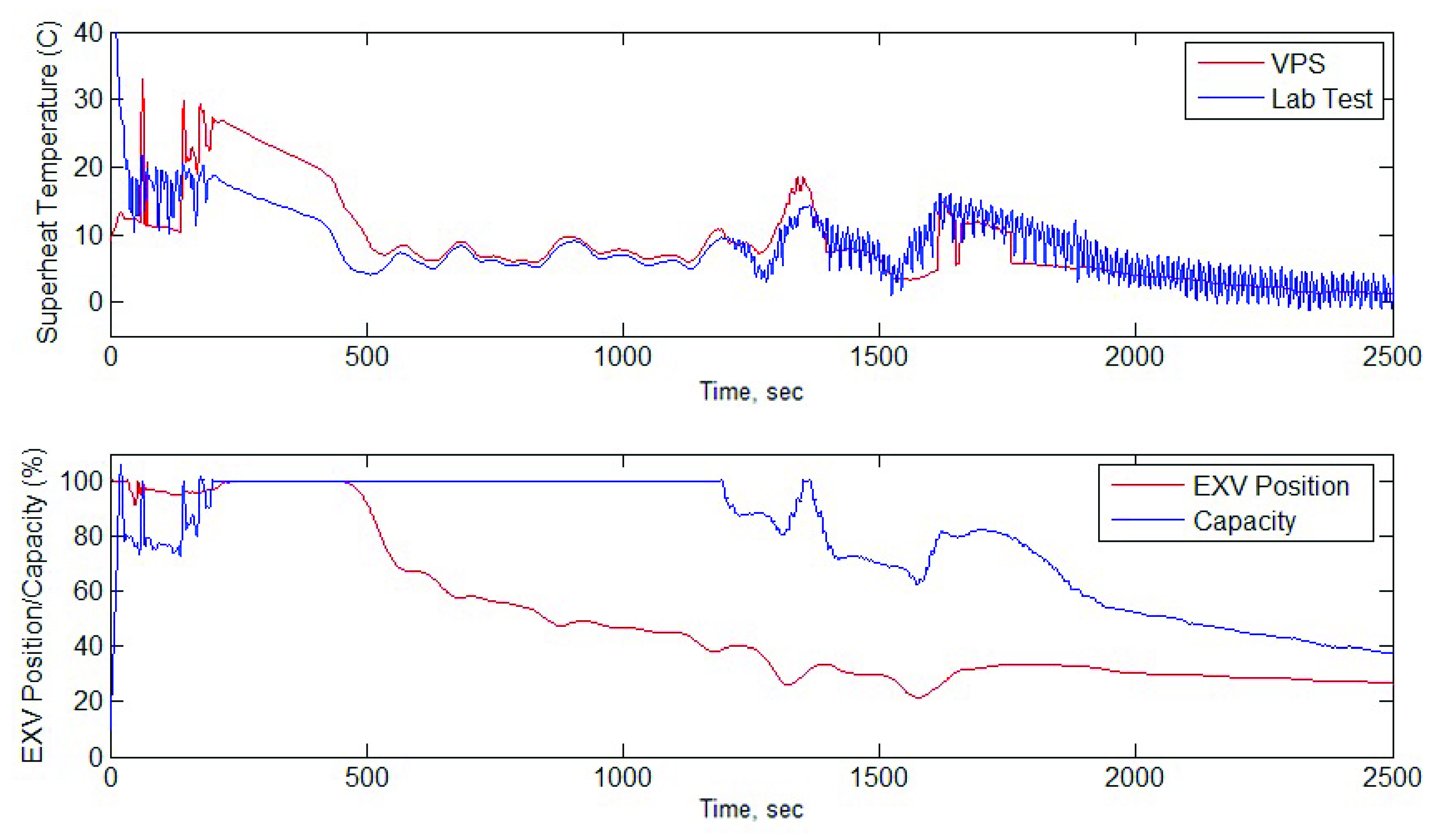
  • The proposed virtual pressure sensor can estimate the pressure/superheat temperature with reasonable accuracy to support EXV control.
  • The proposed method has better accuracy in the pressure/superheat temperature estimation in the full load/near full load conditions than partial load conditions (Figure 6).
  • The pressure/superheat temperature estimate is not applied for the EXV saturation condition when the EXV is fully open at 100% and EXV control is not needed.

4. Electronic Expansion Valve (EXV) Control Using Virtual Pressure Sensor

After the calibration and validation of the virtual pressure sensor, we apply it to EXV control to evaluate its control performance. Instead of using the actual refrigeration system, a virtual simulation environment, called the model in the loop (MIL) simulation platform, is developed to test virtual pressure sensors for EXV control. The MIL simulation platform is shown in Figure 7. The MIL test platform is composed of five modules, including a test case generator, a Virtual Suction Pressure (VSP) pressure/superheat estimation module, control models, refrigeration system dynamic models and a simulation results module. The platform is set up in a Matlab/Simulink environment. The control model and VSP pressure/superheat estimation are built with Simulink. The system selected for this control test is a typical vapor compression refrigeration system which consists of several major components: a two-stage compressor, a fin coil evaporator and condenser, an economizer and thermal and electronic expansion valves. Its dynamic model is developed through Dymola/Modelica and imported into Matlab/Simulink through the functional mockup interface (FMI) toolbox.
Three MIL simulation cases are used to evaluate the VSP performance of estimating the pressure/superheat temperature in EXV control:
  • MIL simulation scenario 1: The refrigerated space temperature was cooled from 37.8 °C to 13.9 °C under 37.8 °C ambient temperature.
  • MIL simulation scenario 2: The refrigerated space temperature was cooled from 37.8 °C to 1.7 °C under 37.8 °C ambient temperature.
  • MIL simulation scenario 3: The refrigerated space temperature was cooled from 37.8 °C to −17.8 °C under 37.8 °C ambient temperature.
For each MIL simulation test, the simulation results are compared between the system with measured pressure and the system with the virtual pressure sensor:
  • Suction pressure: to evaluate the virtual pressure sensor pressure prediction accuracy.
  • EXV position: to evaluate the impact of virtual pressure sensor performance on the EXV controller output.
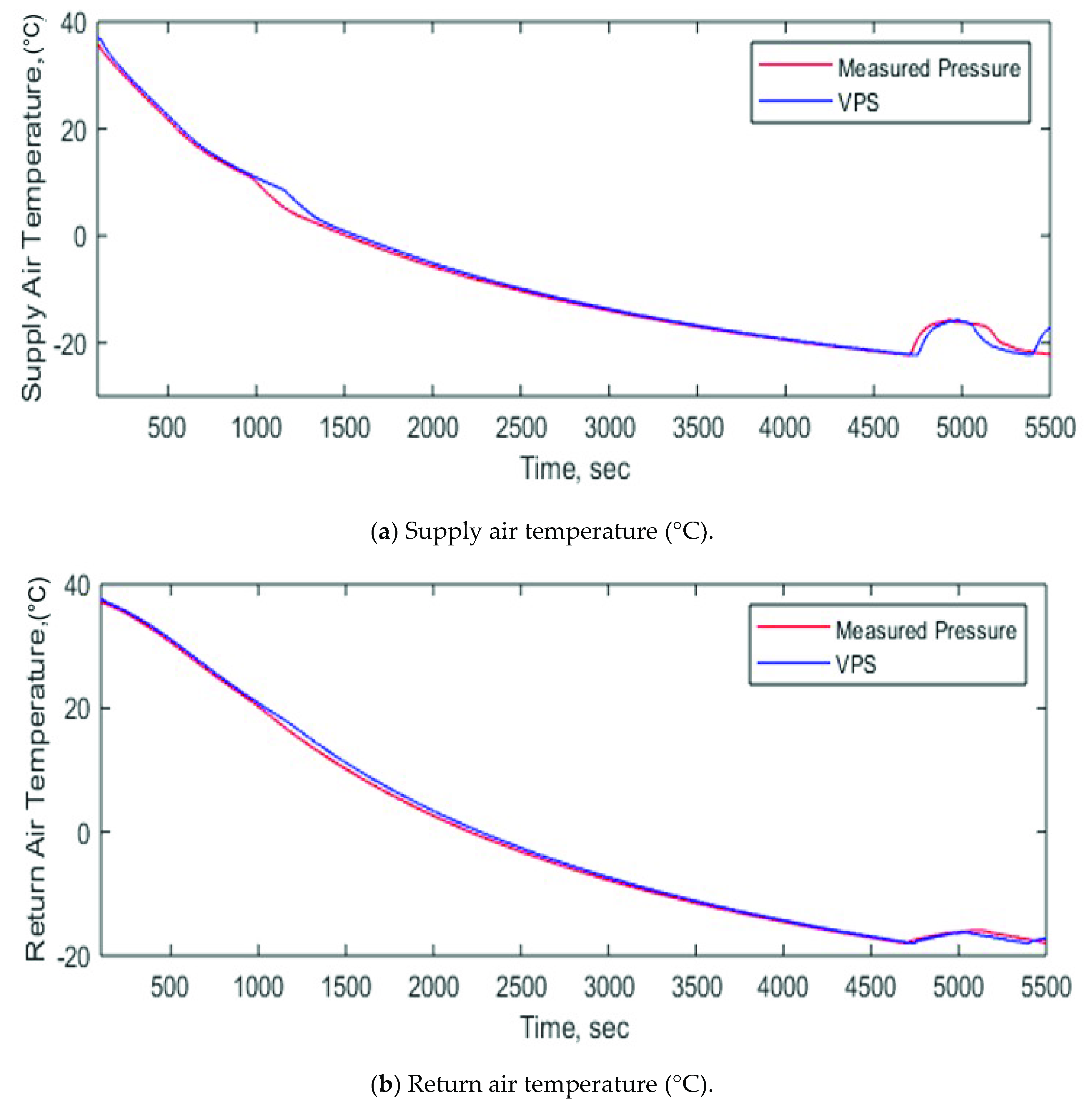
  • Evaporator supply/return air temperature: to evaluate the impact of virtual pressure sensor performance on the controlled temperature.
The EXV control performances with the proposed virtual pressure sensor are shown in Figure 8, Figure 9 and Figure 10. Several key performance variables, supply/return air temperature, EXV opening position and suction pressure, are compared between EXV control based on the measured pressure and EXV control based on the calculated pressure based on the proposed virtual pressure sensor. The MIL simulation results indicate:
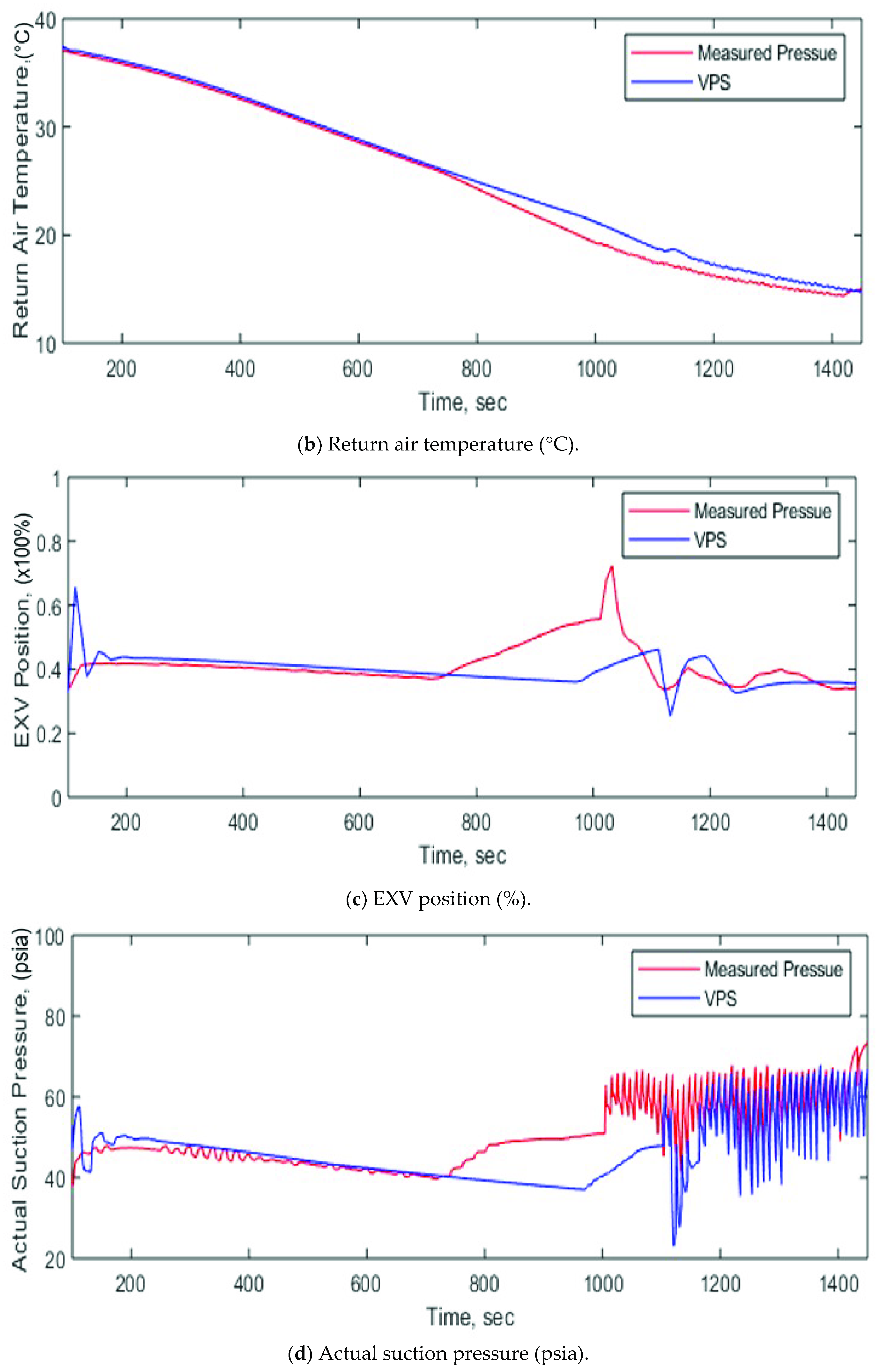
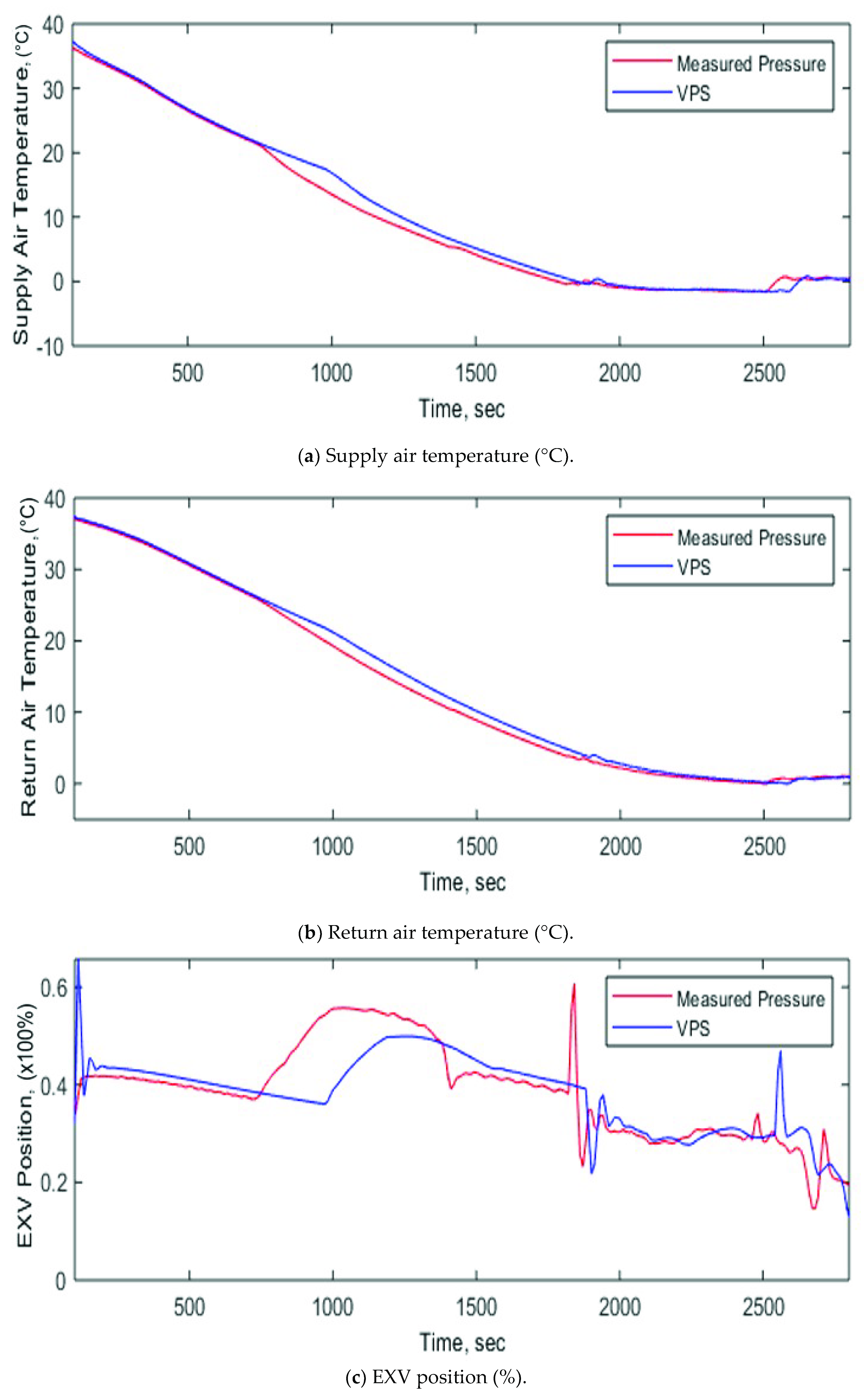
  • The EXV control using the proposed virtual pressure sensor could control the supply/return temperature very well at all three test examples: the virtual pressure sensor-based EXV control maintains almost the same supply/return air temperature as the measured pressure EXV control.
  • The suction pressure calculated by the virtual pressure sensor matches well with the actual measured pressure in most of operating conditions except for a few narrow operation zones, such as the transition zone from full load operation to partial load operation in MIL simulation scenario 1 and a small operation zone during full load operation in MIL simulation scenario 2. These discrepancies result in different EXV opening position. These errors are generally caused by a model error of the virtual suction pressure senor. Fortunately, the impact of these pressure calculation errors on a controlled objective, supply/return air temperature, are relatively small and can be ignored.
  • When the system is running with a compressor pulse width modulation control zone, the calculated suction pressure based on the virtual pressure sensor model agrees with the average actual pressure but cannot match the dynamic characteristics of the actual pressure. The primary reason is that the proposed virtual pressure sensor is a steady-state model and cannot handle the dynamic change of pressure. This drawback of the virtual pressure sensor has little influence on the EXV control performance since the EXV control takes the average pressure signal as input to calculate the control output signal.
In general, the MIL comparison simulation results indicate that the proposed virtual pressure sensor can substitute the actual pressure sensor in terms of EXV control performance. This virtual pressure sensor technology is able to provide additional redundancy and guarantee EXV control in a vapor compression refrigeration system.

5. Conclusions

Superheat control is one of the most important control functions in vapor compression refrigeration systems, since it prevents compressor flooding and maintains system capacity and efficiency. Both temperature and pressure sensors are required for EXVs to control refrigeration system superheat temperatures. It is not abnormal for pressure sensors to malfunction during operation. For a system without redundant pressure sensors, the virtual pressure sensor technology is a cost-effective and convenient method to calculate the pressure to maintain the EXV superheat control. This study developed an easily implemented virtual pressure sensor model to address this issue. The calculated pressures based on the proposed virtual pressure sensor model are compared with measured pressures in three lab tests, which verifies the accuracy of the virtual pressure sensor. A model-based control platform is used to further verify the influence of the virtual pressure sensor on the EXV control performance through three MIL simulation tests. The results are analyzed and it is concluded that the proposed virtual pressure sensor can be used to substitute the actual pressure sensor for EXV superheat control. Further studies can be conducted on how to automatically identify the sensor faults and continuously calibrate the virtual sensor.

Author Contributions

Conceptualization, J.S.; methodology, J.S.; formal analysis, J.S., J.D.; simulation, J.S., B.S.; data curation, J.S. and W.L.; writing—original draft preparation, J.S.; writing—review and editing, J.S., J.D., B.S. and W.L.; All authors have read and agreed to the published version of the manuscript.

Funding

This manuscript has been authored in part by UT-Battelle, LLC, under contract DE-AC05-00OR22725 with the US Department of Energy (DOE). The US government and the publisher, by accepting the article for publication, acknowledges that the US government retains a nonexclusive, paid-up, irrevocable, worldwide license to publish or reproduce the published form of this manuscript, or allow others to do so, for US government purposes. The DOE will provide public access to these results of federally sponsored research in accordance with the DOE Public Access Plan (http://energy.gov/downloads/doe-public-access-plan).

Acknowledgments

Authors would like to thank Joe Hagerman, Teja Kuruganti, Jeff Munk and Borui Cui from Oak Ridge National Laboratory and Shenglan Xuan from Johnson Control International for their discussion, suggestions and support in this work.

Conflicts of Interest

The authors declare no conflict of interest.

Nomenclature

Symbols
AArea, m2
CConstant/parameter
dPPressure drop, pa
CFCorrection factor
Exv%Electronic expansion valve opening, %
mMass flow rate, kg/s
NCompressor speed, rpm
PPressure, pa
TTemperature, °C
VVolumetric flow rate, m3/s
ρDensity, kg/m3
γIsentropic exponent
Subscripts and abbreviations
airAir side
compCompressor
dis, dCompressor discharge port
dispCompressor displacement
exv, EXVElectronic expansion valve
inElectronic expansion valve inlet
initInitial value
normNormalized value
outElectronic expansion valve outlet
suc, sCompressor suction port
0,1,2,3State number, constant number

References

  1. Andiroglu, E.; Wang, G.; Song, L.; Kiamehr, K. Development of a Virtual Pump Water Flow Meter Using Power Derived from Comprehensive Energy Loss Analysis. Sci. Technol. Built Environ. 2016, 22, 214–226. [Google Scholar] [CrossRef]
  2. McDonald, E.; Zmeureanu, R. Virtual Flow Meter for Chilled and Condenser Water for Chiller: Estimates Versus Measurements. Sci. Technol. Built Environ. 2016, 22, 178–188. [Google Scholar] [CrossRef]
  3. Bach, C.K.; Groll, E.A.; Braun, J.E.; Horton, W.T. Development of a Virtual EXV Flow Sensor for Applications with Two-Phase Flow Inlet Conditions. Int. J. Refrig. 2014, 45, 243–250. [Google Scholar] [CrossRef]
  4. Li, H.; Braun, J. Virtual Refrigeration Pressure Sensors for Use in Monitoring and Fault Diagnosis of Vapor-Compressor Equipment. HAVC&R Res. 2009, 15, 597–616. [Google Scholar]
  5. Kim, W.; Braun, J. Performance Evaluation of a Virtual Refrigerant Charge Sensor. Int. J. Refrig. 2013, 36, 1130–1141. [Google Scholar] [CrossRef]
  6. Kim, W.; Braun, J. Extension of a Virtual Refrigeration Charge Sensor. Int. J. Refrig. 2015, 55, 224–235. [Google Scholar] [CrossRef] [Green Version]
  7. Li, H.; Braun, J. Development, Evaluation and Demonstration of a Virtual Refrigerant Charge Sensor. HAVC&R Res. 2009, 15, 117–136. [Google Scholar]
  8. Zhao, X.; Yang, M.; Li, H. A Virtual Condenser Fouling Sensor for Chiller. Energy Build. 2012, 52, 68–76. [Google Scholar] [CrossRef]
  9. Hjortland, A.; Braun, J. Virtual Sensors for Rooftop Unit Air-Side Diagnostics. Sci. Technol. Built Environ. 2016, 22, 189–200. [Google Scholar] [CrossRef]
  10. Li, H.; Braun, J. Decoupling Features and Virtual Sensors for Diagnosis of Faults in Vapor Compression Air Conditioners. Int. J. Refrig. 2007, 30, 546–564. [Google Scholar] [CrossRef]
  11. Yoon, S.; Yu, Y. Strategies for Virtual In-Situ Sensor Calibration in Building Energy Systems. Energy Build. 2018, 172, 22–34. [Google Scholar] [CrossRef]
  12. Wang, P.; Yoon, S.; Wang, J.; Yu, Y. Automated Reviving Calibration Strategy for Virtual In-Situ Sensor Calibration in Building Energy Systems: Sensitivity Coefficient Optimization. Energy Build. 2019, 198, 291–304. [Google Scholar] [CrossRef]
  13. Kuehn, T.H.; Ramsey, J.W.; Threlkeld, J.L. Thermal Environmental Engineering, 3rd ed.; Prentice Hall: Upper Saddle River, NJ, USA, 1998. [Google Scholar]
  14. Xue, Z.; Shi, L.; Ou, H. Refrigeration Flow Characteristics of Electronic Expansion Valve Based on Thermodynamic Analysis and Experiment. Appl. Therm. Eng. 2008, 28, 238–243. [Google Scholar]
Figure 1. Compressor and Electronic expansion valve (EXV) scheme in vapor compression refrigeration system.
Energies 13 04917 g001
Figure 2. Pressure calculation based on compressor and EXV characteristics.
Energies 13 04917 g002
Figure 3. (a) Compressor; (b) EXV model calibration.
Energies 13 04917 g003
Figure 4. Test Case 1—superheat temperature estimation: Virtual Pressure Sensor (VPS vs. test.
Energies 13 04917 g004
Figure 5. Test Case 2—superheat temperature estimation: VPS vs. test.
Energies 13 04917 g005
Figure 6. Test Case 3—superheat temperature estimation: VPS vs. test.
Energies 13 04917 g006
Figure 7. Model in the Loop (MIL) test framework.
Energies 13 04917 g007
Figure 8. MIL simulation results for scenario 1.
Energies 13 04917 g008aEnergies 13 04917 g008b
Figure 9. MIL simulation results for scenario 2.
Energies 13 04917 g009aEnergies 13 04917 g009b
Figure 10. MIL simulation results for scenario 3.
Energies 13 04917 g010aEnergies 13 04917 g010b
Table 1. Model parameters.
Model Parameters
γ1.13
Ncomp3600 rpm
Vdisp1.45 × 10−4 m3
C00.0139
C1−2.45783 × 10⁻⁵
C22.7928 × 10−6
C3−1.88744 × 10⁻⁸

