Article

Cement Integrity Loss due to Interfacial Debonding and Radial Cracking during CO2 Injection

1
Key Laboratory of Petroleum Engineering, China University of Petroleum, Beijing 102249, China
2
Beijing Key Lab of Heating, Gas Supply, Ventilating and Air Conditioning Engineering, Beijing University of Civil Engineering and Architecture, Beijing 100044, China
3
Key Laboratory of Applied Mechanics (AML), Department of Engineering Mechanics, Tsinghua University, Beijing 100084, China
*
Author to whom correspondence should be addressed.
Energies 2020, 13(17), 4589; https://doi.org/10.3390/en13174589
Submission received: 21 July 2020 / Revised: 26 August 2020 / Accepted: 1 September 2020 / Published: 3 September 2020

Abstract

:
Cement provides zonal isolation and mechanical support, and its integrity is critical to the safety and efficiency of the CO2 injection process for geologic carbon storage. This work focuses on interfacial debonding at wellbore interfaces and radial cracking in cement during CO2 injection. It adopts the definition of the energy release rate (ERR) to characterize the propagation of cracks. Based on the finite element method, the proposed model estimates the ERRs of both types of cracks with practical wellbore configurations and injection parameters. Further parametric studies reveal the effects of cement’s mechanical and thermal properties and the crack geometry on crack propagation. Simulation results show that the ERRs of interfacial and radial cracks would surpass 100 J/m2 with typical cement properties. The cement’s thermal expansion coefficient is the most influential factor on the ERR, followed by its Young’s modulus, Poisson’s ratio, and thermal conductivity. The initial sizes and positions of the cracks are also important parameters for controlling crack propagation. Moreover, non-uniform in situ stresses would accelerate crack propagation at the interfaces. These findings are valuable and could help to optimize cement sheath design in order to ensure the long-term integrity of wells for geological carbon storage.

Graphical Abstract

1. Introduction

Carbon capture and storage (CCS) is one of the potential climate change mitigation strategies for reducing carbon dioxide (CO2) emissions in the atmosphere [1,2]. The International Energy Association (IEA) predicts that CCS will contribute 24% to the cumulative CO2 emission reductions from clean technologies [3]. Geologic CO2 storage—the injection of CO2 into underground formations without economic exploitation, such as deep saline aquifers or depleted oil and gas reservoirs, both on-shore and off-shore—contributes largely to this goal. Secure geological storage of CO2 is supposed to limit leakage rates to 0.01% per year [4]. Oil and gas wells are the primary channels for injection of CO2 into the subsurface, but are also potential pathways for CO2 to escape from the reservoir. Hence, long-term well integrity is necessary to inhibit fluid leakage and is essential to CO2 storage security [5,6]. The cement sheath placed between the casing and the formation is the main wellbore barrier, which provides zonal isolation and mechanical stability [7,8]. Therefore, cement integrity is critical to geologic CO2 storage.
During the operation or abandonment phases, cement integrity can be jeopardized by insufficient well completion, mechanical damage caused by wellbore stresses, or property deterioration owing to chemical attack [9]. Generally, failure modes in the cement sheath are identified as radial cracking, compressive shear failure, interfacial debonding between the casing and cement or between cement and the formation, channelization through small cracks, and incomplete cementing [7,10]. Geochemical interactions between subsurface fluids and wellbore barrier materials take a long time, while mechanical stresses during CO2 injection cause severe damage to cement. One of the main challenges in maintaining cement integrity for CCS is the temperature perturbation caused by injecting cold CO2 fluid into relatively warmer formations. The contraction of wellbore materials due to a temperature drop can aggravate interfacial debonding and radial cracking in cement [11]. Experimental observations have demonstrated that interfacial defects would grow under cyclic thermal loading [12,13]. Moreover, imposing temperature drops in the casing could lower the cement bond strength by about 69% [14]. Pre-existent radial cracks in cement would also be extended when applying mechanical and thermal loading to well section samples [11]. Extreme cooling could even create radial fractures in the cement. These kinds of damage severely endanger the cement integrity during CO2 injection.
Conventional design methods for cement sheaths are based on stress analysis and material strength criteria, which provide a critical loading threshold [15,16]. Different models have been developed to estimate wellbore stresses induced by thermal perturbations and to evaluate the risk of cement failure [17,18,19]. Thiercelin et al. (1998) presented a linear thermoelastic model that characterizes the mechanical response of a cemented wellbore under thermal loading [17]. They concluded that the thermoelastic properties of the casing, cement, and formation are critical to cement damage. Considering the thermo-poro-elasto-plastic behavior of cement, Bois et al. conducted a comprehensive analysis of the creation of micro annuli at cement-sheath interfaces [20]. Their work pointed out that temperature and pressure increase-decrease cycles are some of the critical configurations leading to micro annuli. Nygaard et al. proposed a 3D finite element model to assess the risk of forming leakage pathways through thermal and pressure fluctuations during CO2 injection in the target near Wabamun Lake, Alberta [21]. They revealed that a cement structure with a large Young’s modulus and Poisson’s ratio is more likely to cause debonding and tensile failure. Combining a two-phase flow model and heat conduction analysis, Aursand et al. studied the effects of injection parameters on wellbore stresses during CO2 injection cycles from ships [22]. Their simulation showed that colder injection temperatures or longer pauses between injections could increase thermal stresses enough to induce debonding at the casing-cement interface.
Strength criteria usually assume that the material is intact and has no defects. However, even if the cementing job is of good quality at the time of completion, the cement sheath will inevitably contain small cracks [23]. Theoretical calculations demonstrate that the stress field at a crack tip turns to infinity, which means no strength criterion is available. Fracture mechanics solves this problem by introducing alternative parameters such as the energy release rate (ERR) and stress intensity factor (SIF) [24]. The according failure criterion compares these parameters with the material’s fracture toughness. Recently, some researchers have shifted to evaluating well integrity through this criterion [10,25,26]. Wang and Taleghani developed a 3D finite element model to simulate the growth of delamination cracks driven by the excessive fluid pressure provided by the leakage at the casing shoe [10]. Material interfaces were represented by pre-inserted cohesive elements, which showed that the tangential stress has a significant effect on failure initiations. Wang et al. calculated the energy release rate for tunneling of small cracks in cement, along with the well depth [27]. They visualized fail-safe conditions that rely on material properties and loading circumstances but require no measurement of crack sizes. Using finite element simulations, Andrade and Sangesland evaluated the influences of casing stand-off positions and initial defects in the cement on well integrity under thermal-related loading events [28]. They presented different failure modes in cement with random input properties of wellbore components and testified that initial defects could exacerbate cement damage. Roy et al. estimated the stress intensity factor of a circumferential crack in cement near the cement-formation interface during CO2 injection [29]. They investigated the effects of the injection temperature, in situ horizontal stresses, and cement’s thermomechanical properties on the stress intensity factor. Their work suggested that injecting CO2 at sub-zero temperatures causes high in situ stresses. Dong et al. assessed cement integrity during CO2 injection using a single-phase flow model and an analytical approach for analysis of stress and the stress intensity factor for a radial crack in the cement [26,30]. They indicated that lowering the injection temperature or increasing the injection rate and duration can promote radial cracking.
Despite the above studies, efforts are still needed to understand the propagation of pre-existent cracks in cement during CO2 injection. For instance, the previous study demonstrated that in situ stresses could reduce the stress intensity factor to a great extent [29]. However, the propagation of interfacial cracks is mode dependent [31]. When subjected to non-uniform in situ stresses, the interfacial crack at the casing-cement or cement-formation interface would be extended in a mixed mode. Higher non-uniform in situ stresses may prompt interfacial crack extension due to the induced shear stress. Apart from this, the mechanical responses of interfacial and radial cracks in cement during CO2 injection remain unclear. This study aims to reveal the impacts of cement’s mechanical and thermal properties, initial crack sizes and positions, as well as in situ stresses on interfacial debonding and radial cracking in wellbore components. Using the finite element method, we estimate the energy release rates of interfacial and radial cracks with realistic wellbore configurations and injection parameters. A further study investigates the variation of ERR with cement properties and fracture geometries. Then, we discuss the influence of in situ horizontal stresses on cracking in cement or at interfaces. The results show that the ERR of interfacial and radial cracks would be more than 100 J/m2 during CO2 injection under certain conditions, which poses a high risk to cement integrity.

2. Modeling for Crack Propagation

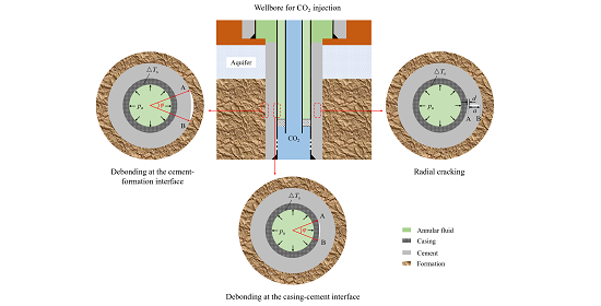
2.1. Basic Features of the Model

Generally, wellbores with poor zonal isolation are likely to provide pathways for the sequestrated CO2 to escape. Figure 1 is a schematic of a vertical injection well with casing and cementing. The injected cold CO2 would induce contraction in wellbore barriers, which poses a threat to the cement integrity. Previous studies indicated that the highest temperature drop occurs at the bottom hole [22,30]. Hence, we focus here on the wellbore section just above the injection zone. As aforementioned, the cement sheath contains defects like the radial or interfacial cracks. The upper right, lower left, and lower right sections of Figure 1 illustrate a radial crack and interfacial cracks at the casing-cement and cement-formation interfaces, respectively. Let A and B denote the left and right tips of the radial crack, respectively. Here, a is the crack length and d represents the distance from A to the casing-cement interface. For interfacial cracks, A and B are the upper and lower tips, respectively, and φ is the central angle of the two arc cracks, which characterizes the crack length. Inside the casing, the annular fluid applies a pressure denoted as pa. During CO2 injection, the wellbore section would encounter a temperature reduction, so we use ΔTs to represent the temperature difference between the initial state and the injection on the casing’s inner surface.
Some primary assumptions must be made in order for the model to simulate crack propagation:
(1)
The model undertakes a plane strain condition to estimate the stress in the wellbore, since the vertical deformation is much smaller than the horizontal deformation [30];
(2)
The casing, cement, and formation are all linear isotropic elastic materials. Although this assumption is not practical, it is sufficient to describe the mechanical responses of cracks and may reduce the computational time [26];
(3)
Because of the linear elastic property, once the wellbore is drilled, the stress on its inner surface is released. After this, the current model does not apply in situ stress to the well section;
(4)
This model does not consider the cement’s initial stress after setting, since its calculation is controversial both in academia and the industry. The prime purpose of the model is to provide the energy release rates of interfacial and radial cracks caused by the variations of the temperature and pressure;
(5)
The wellbore components are bonded rigidly, except for the interfacial cracks at the casing-cement and cement-formation interfaces;
(6)
Neglecting the thermal contact resistance at the interfaces, the model determines the temperature distribution through heat conduction analysis in the steady state.

2.2. Modeling Approach

Energy release rates and stress intensity factors are two parameters from linear elastic fracture mechanics (LEFM) [24]. As we assume the casing, cement, and the formation are all linearly elastic, we use ERR to characterize the crack propagation. Additionally, ERR is convenient for dealing with interfacial cracks. The criterion for crack propagation states that a crack will propagate when its energy release rate is higher than the material’s resistance to fracturing. One of the most concise forms of ERR is an infinite plate applied to tensile plane stresses with a crack length of 2a perpendicular to the tension [24]:
G = π σ 2 a E
where G denotes the energy release rate and σ is the applied far-field plane stress. The significance of Equation (1) is that it introduces the crack length into a mechanical parameter named the energy release rate. It also infers that long cracks or high stresses would induce a high energy release rate. Fracture mechanics divides cracks into three modes: (i) mode I (opening), (ii) mode II (in-plane shearing), and (iii) mode III (out-of-plane shearing) [24]. A combination of two of the three modes is called a mixed mode. For a crack in a single material, the energy release rate is related to the stress intensity factor as [24,28]:
G I = K I 2 E
where GI denotes the energy release rate in mode I and KI is the stress intensity factor at the crack tip. Equation (2) remains valid for a crack in mode III.
An interfacial fracture between two dissimilar materials is similar to a crack in a single material under a mixed mode. According to fracture mechanics, interfacial cracks will propagate when the flowing inequality exists [31]:
G i = G i , I + G i , II > Γ ic
where Gi represents the energy release rate of an interfacial crack; Gi,I and Gi,II are the ERRs of mode I and mode II, respectively; and Γic is the interfacial toughness related to the materials’ properties, geometries, and loading rates. For cracks embedded in a single material in mode I (e.g., radial cracking), Equation (3) reduces to:
G I Γ c
where Γc is the fracture toughness for a single material.
It is very difficult to predict the ERRs for complex geometries under non-uniform loads using analytical methods. Here, we adopt the finite element method to estimate the ERRs of interfacial and radial cracks using the commercial software ABAQUS (DASSAULT SYSTÈMES, Vélizy-Villacoublay, France, 2016), which provides several techniques to simulate fracture propagation. We choose the virtual crack closure technique (VCCT) and counter integrals to estimate the ERR for interfacial and radial cracks, respectively. The VCCT is based on the assumption that the energy required to extend a crack by a certain amount is the same as the energy required to close the crack by the same amount [32]. The energy release rates in mode I and mode II are calculated as [32]:
G I = 1 2 Δ a Y i v i v i ,   G II = 1 2 Δ a X i u i u i
where Δa is the length of the elements at the crack tip, Yi and Xi are the tension and shear force, respectively; V′i and v′′i are the vertical displacements at the upper and lower surfaces of the crack, respectively; u′i and u′′i are the lateral displacements of the crack’s surfaces.
Equation (5) shows that VCCT can separate fracture modes, which is convenient for interfacial crack propagation analysis. Additionally, it is valid for an arc crack, as shown in the bottom of Figure 1. Although VCCT is also available to code with straight fractures, we use counter integrals to calculate the ERR for radial cracking. Counter integrals are relatively more convenient than VCCT in modeling using ABAQUS. This method is extended from the J-integral and can offer ERR and SIF values. LEFM demonstrates that the J-integral is equal to the energy release rate, as long as the plastic zone near the crack tip is small (small-scale yield) [24]. However, counter integrals are cumbersome for curved fractures.
Finally, we add some complementary details for the modeling details. When simulating fracture propagation, each model contains only one kind of crack, as shown in Figure 1. The casing, cement, and formation are meshed using four-node bilinear plane strain elements. The central angle φ measures the interfacial crack length, as depicted in Figure 2a,b. The VCCT is required to bond the elements adjacent to each other at interfaces and outside the angle φ to mimic a rigid connection (red points in Figure 2a,b), while the remaining unbonded elements represent the crack. We control the mesh size to arrange 2880 elements along the circumference of the casing and cement. Appendix A validates the insensitivity of the ERR calculation to the element number. A modeling issue exists, that whereby VCCT cannot support coupled temperature-displacement analysis steps in ABAQUS. To circumvent this problem, we have to create two models in one project in ABAQUS. One model solves the heat conduction through the casing to the surrounding formation and provides the temperature distribution. The other calculates the ERR of the interfacial cracks with the boundary condition predefined from the previous model. For radial cracking, the length of the radial crack in cement is denoted by a and the distance from the left tip to the casing-cement interface is d (see Figure 1b). Since the highest tensile hoop stress is located at the casing-cement interface [30], we set d = 0.5 mm in our model to obtain conservative results. Compared with interfacial debonding, the element number required to guarantee convergence for radial cracking is much lower. Only 240 and 480 elements are laid out at the circumferences of the casing and cement, respectively. The vicinity of the crack tip is refined for counter integrals (Figure 2c).

2.3. Model Parameters

The modeling parameters include the geometry of the wellbore, the mechanical and thermal properties of the barriers, and the loading conditions. A series of geometrical, mechanical, and thermal parameters for a reference state is listed in Table 1. These parameters are typical in CO2 injection wells. Notably, the outer radius of the formation is much larger than that of the cement sheath.
The loading parameters also define the boundary conditions of the finite element model. The primary boundaries of the current model are the inner surface of the casing and the outer surface of the formation, as shown in Figure 1. External loading and temperature fluctuation act on these boundaries. The pressure inside the casing, pa, is the leading cause of the tensile hoop stress in cement, which is dependent on the density of the annular fluid and the well depth. The literature reports that the major gas fields for CO2 sequestration are 900–3500 m deep [30,33]. To account for severe situations, we consider a well depth of 3000 m with a water-based annulus fluid, which would produce a pressure of about 30 MPa on the casing, i.e., pa = 30 MPa. Zero stress is applied to the outer boundary of the formation in line with the model assumptions. The temperature variation in the wellbore during injection is another major factor that can induce thermal stresses in cement. Some studies have shown that temperature change is related to the injection temperature, rate, time, and wellbore geometry. According to field practices, the injection temperature ranges from −20 °C to 20 °C, the injection rate for pipeline delivery is up to 30 kg/s, and for ship delivery is up to 95 kg/s [22]. The wellbore flow model infers that low injection temperatures or fast injection rates would induce a significant temperature drop in the wellbore components [30]. In this study, we set the injection temperature, rate, and duration as equal to −20 °C, 20 kg/s, and 250 days, respectively. These injection and well completion configuration parameters (as listed in Table 1) lead to a temperature drop of −65.5 °C on the casing at the bottom hole [30]. Then, ΔTs = −65.5 °C, so we assume that the temperature on the outer surface of the formation is unaffected, since it is far from the borehole. It is reported that this combination of annular pressure and temperature reduction on the casing can produce both high tensile radial and hoop stresses in cement [30].

3. Results

The extension of both interfacial and radial cracks could be driven by the variation of the wellbore stress state. In Section 2, we choose a set of parameters to apply high tensile radial and hoop stresses to the cement sheath. Then, we implement a numerical simulation to estimate the energy release rates of interfacial and radial cracks in a well section with a casing-cement-formation structure. A parametric study is performed to investigate the effects of cement’s mechanical and thermal properties on the energy release rate. The considered properties of cement are its Young’s modulus, Poisson’s ratio, thermal expansion coefficient, and thermal conductivity. Given the strong dependence of ERRs on fracture lengths, our work also analyzes the influence of the initial sizes and positions of defects. During the simulation, we vary the central angle to influence interfacial debonding and the fracture length to influence radial cracking. The following sections present the results.

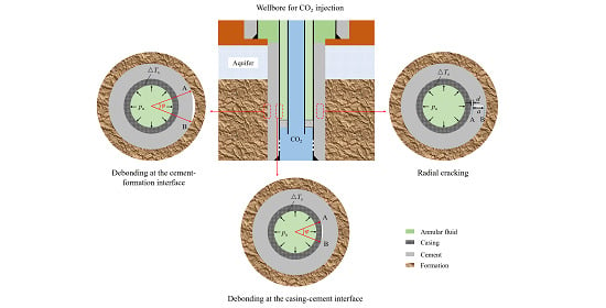
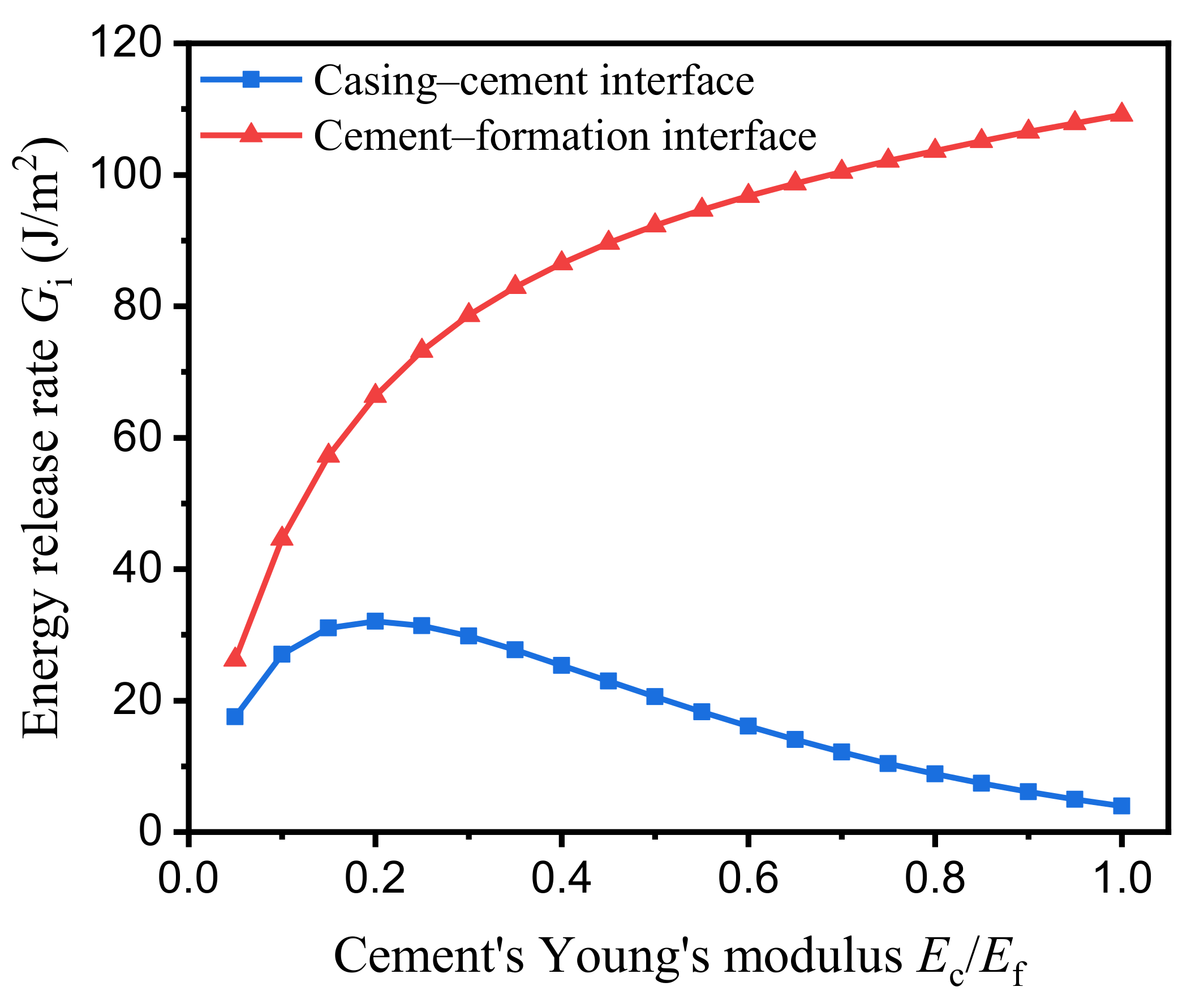
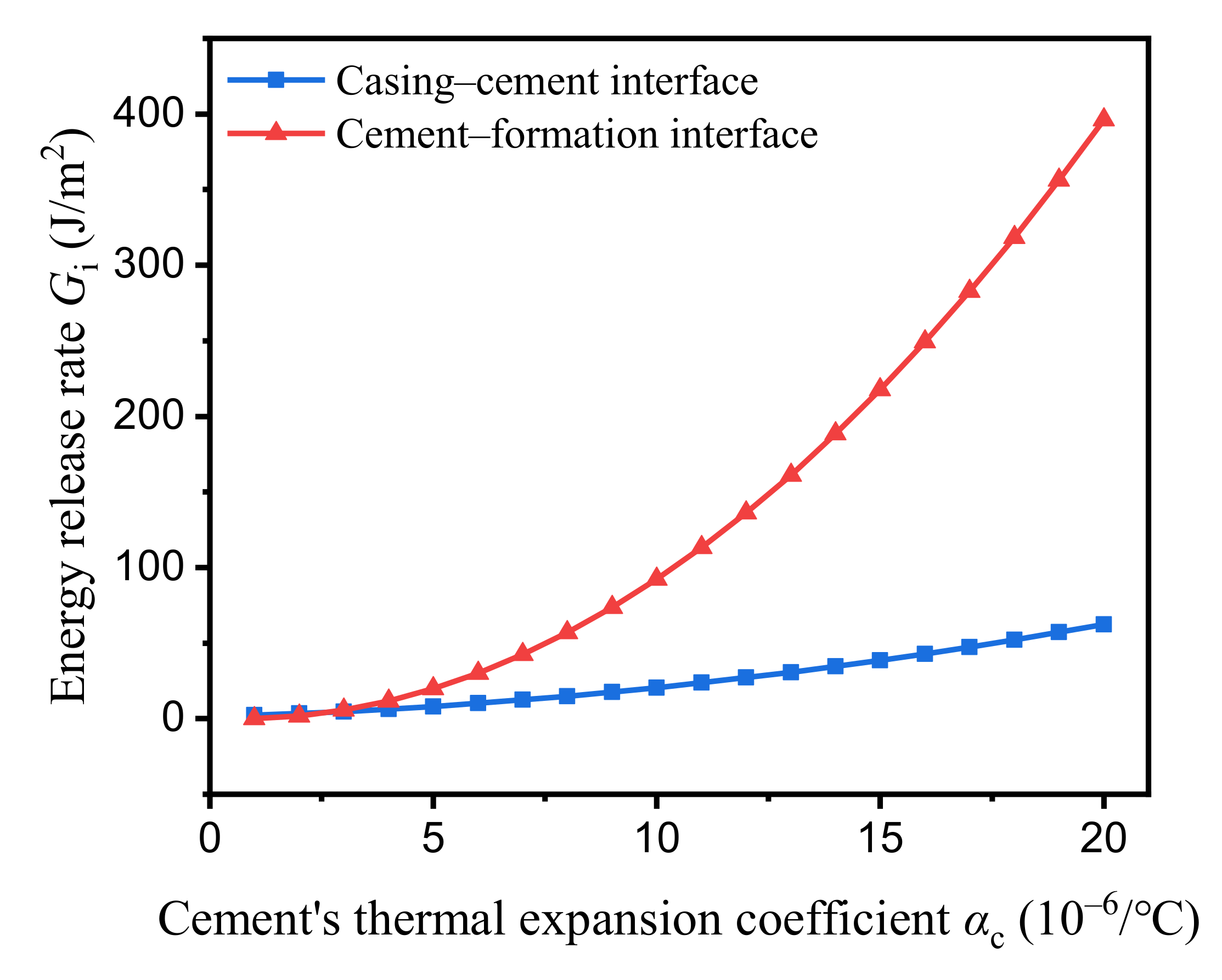
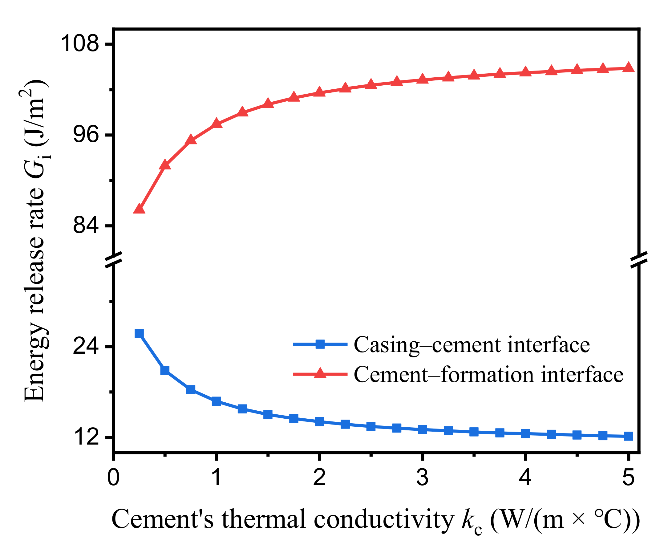
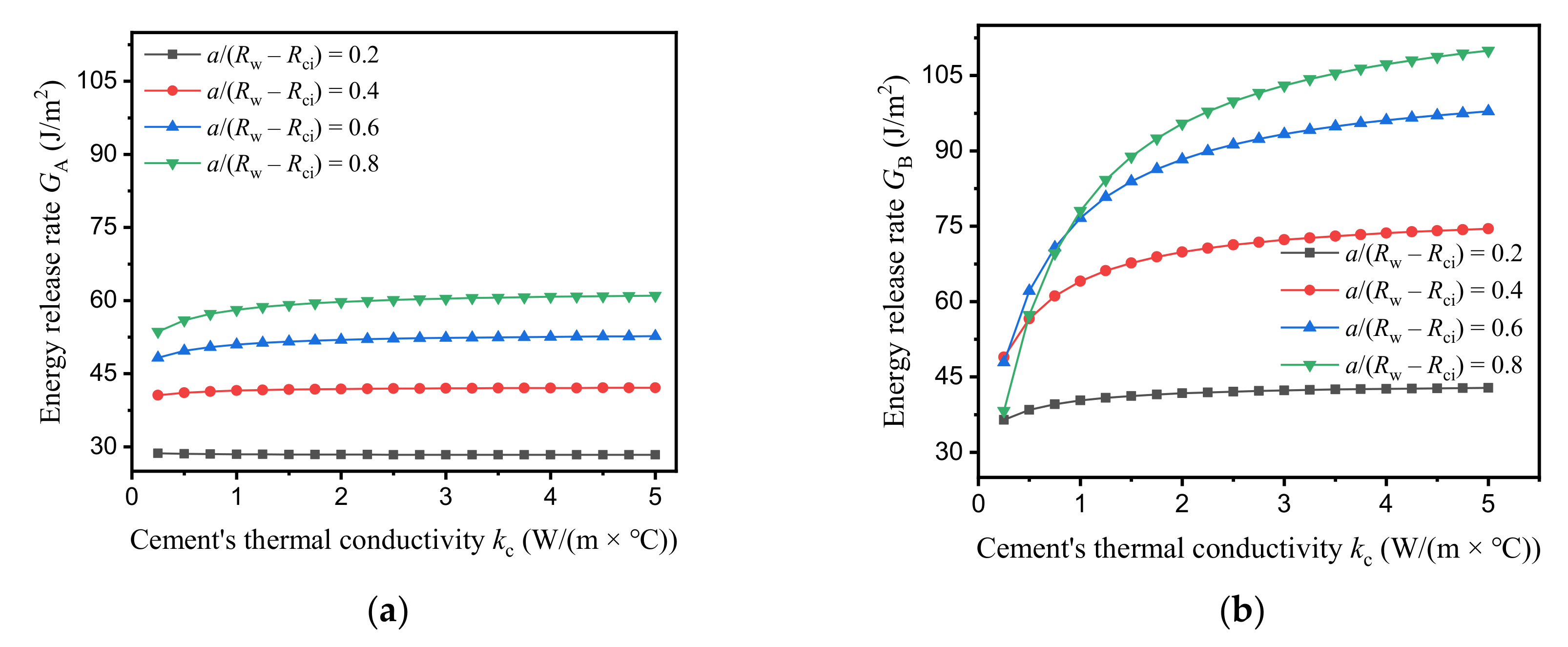
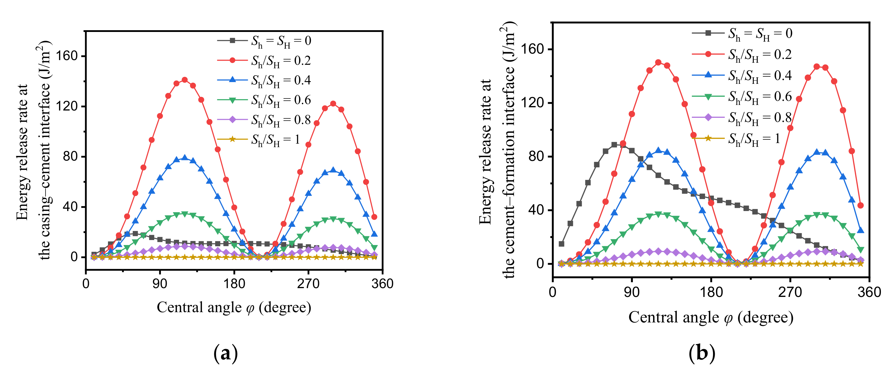
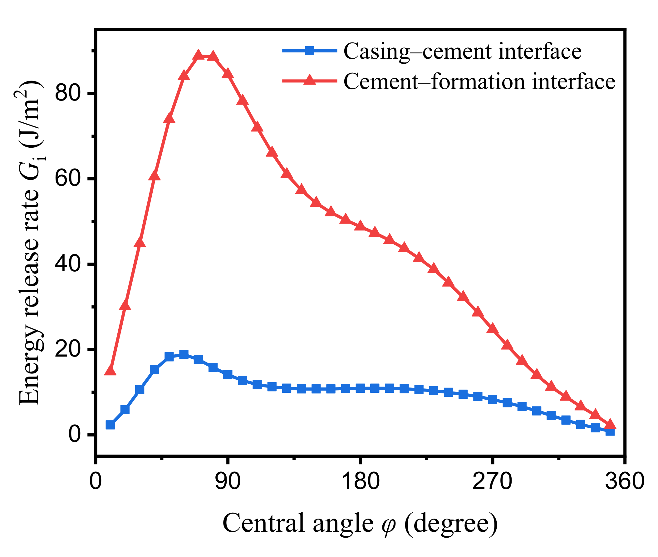
3.1. Interfacial Debonding

Before investigating the effects of cement’s properties, we first inspect the impacts of the interfacial crack’s initial size. Varying the central angle φ (see Figure 1) changes the interfacial crack length. As the geometry (including the interfacial crack), loading, and boundary constraints are symmetric about the angular bisector of φ, the ERRs at both tips of the interfacial crack are equal to each other. Fracture mechanics demonstrates that interfacial cracks have a very complicated stress state around the crack front. The stress will oscillate near the crack tip owing to the elastic mismatch between two dissimilar materials [31]. Figure 3 illustrates this complication, whereby the energy release rate fluctuates with the central angle of the interfacial crack. Both ERRs at the casing-cement interface and the cement-formation interface exhibit a similar trend regarding the crack length, whereby they increase quickly when φ increases and then decrease gradually with a shoulder as φ approaches 350°. The energy release rate reaches a maximum value within the range of the central angle. Specifically, the maximum ERR of the crack at the casing-cement interface is 18.8 J/m2 at φ = 60° and for the crack at the cement-formation interface is 88.8 J/m2 at φ = 70°. To the authors’ knowledge, there is no report on the interfacial toughness between the steel casing and oil well cement or between oil well cement and formations. The shear bond strength of these interfaces has been measured by some researchers as being several MPa [34,35]. Concrete strength studies for construction and building show that the cement’s interfacial toughness with fiber-reinforced steel is several tens of J/m2 [36]. On this basis, both interfacial cracks are very prone to extension under the current injection operation and downhole conditions. To maintain an intact interface, the maximum ERR must be less than the interfacial resistance. As the central angle increases, the ERR at the cement-formation interface is always higher than the one at the casing-cement interface. This indicates that the cement-formation interface is more likely to debond than the casing-cement interface.
Considering severe situations, we fix the central angles of the cracks at the casing-cement and cement-formation interfaces at 60° and 70°, respectively. Cement’s mechanical properties have a dramatic impact on wellbore stresses. Previous studies have demonstrated that stiffer cement will induce a higher stress state in the wellbore [17,37]. This conclusion fits the ERR observed at the cement-formation interface, as illustrated by the red triangles in Figure 4. We use the ratio of cement’s Young’s modulus (Ec) to that of the formation (Ef) as the horizontal axis. The energy release rate at the cement-formation interface grows with Ec/Ef non-linearly. Gi reaches 109.1 J/m2 for the cement-formation interface as Ec/Ef approaches 1. However, the energy release rate of the crack at the casing-cement interface first increases as Ec/Ef increases to 0.2 and then drops gradually in line with Ec/Ef. Its maximum value is 32.1 J/m2 at Ec/Ef = 0.2, which means that soft cement is not always beneficial in terms of cement integrity. The differences in the changing tendencies between these two interfacial cracks lie in the complex mechanical debonding behavior. The energy release rate of an interfacial crack is not only dependent on the stress state at the crack front, but is also dependent on the elastic mismatch between the materials.
A material’s Poisson’s ratio measures the lateral deformation corresponding to the longitudinal deformation, which also plays a critical role in the elastic mismatch between different materials. Figure 5 shows that increasing cement’s Poisson’s ratio (νc) would enlarge the energy release rates at both interfaces. As νc changes from 0.05 to 0.35, the Gi value for the casing-cement interface goes from 10.7 J/m2 to 35.9 J/m2, while for the cement-formation interface it goes from 50.3 J/m2 to 148.3 J/m2. In contrast, cement’s Poisson’s ratio has more influence on the energy release rate at the interfaces than its Young’s modulus. For instance, increasing the νc (from 0.05 to 0.2) three-fold will increase the ERR at the cement-formation interface by nearly 65% (from 50.3 J/m2 to 82.8 J/m2), however the same increase for Ec (Ec/Ef: from 0.2 to 0.8) increases the ERR by 56% (from 66.4 J/m2 to 103.7 J/m2). The slope of the ERR-νc curve for the cement-formation interface is also steeper than that of the ERR-Ec/Ef curve for the same interface, which means the ERR increases faster with νc than Ec. The results indicate that engineers should carefully select the Poisson’s ratio of the cement to reduce the risk of interfacial debonding.
Thermal deformations in barrier components are the primary sources of wellbore stresses. They strongly depend on the material’s thermal expansion coefficient. Injecting liquid CO2 leads to a temperature reduction in the wellbore, which induces shrinkage in the casing, cement, and formation. Radial shrinkage promotes debonding at the interfaces. Figure 6 plots the evolution of ERR with cement’s thermal expansion coefficient (αc). It is easy to see that high thermal expansion coefficients lead to greater ERR values at both interfaces. This is most prominent when αc is very small, whereby the energy release rate nearly vanishes. This means that a cement type with a low thermal expansion coefficient could reduce the risk of debonding to a great extent. As αc increases, the ERR at the two interfaces grows non-linearly. The energy release rate at the cement-formation interface approaches 400 J/m2 at αc = 2 × 10⁻⁵/°C, which is much greater than the interfacial resistance. Even for the casing-cement interface, the energy release rate is over 60 J/m2 when αc = 2 × 10⁻⁵/°C. Therefore, inhibiting the shrinkage of cement during CO2 injection is important in order to maintain the cement integrity.
This study considers the steady heat conduction between the barrier materials, which means the thermal conductivity of cement (kc) determines the temperature distribution. A greater kc value means the cement’s temperature is closer to that of the casing. On the other hand, small kc values mean the cement’s temperature is similar to that of the formation. Figure 7 shows that the consequence of increasing means that kc will reduce the ERR at the casing-cement interface but increase the ERR at the cement-formation interface. Compared with the other three properties, the influence of the thermal conductivity of cement on the interfacial debonding is trivial. When kc varies from 0.25 W/(m × °C) to 5 W/(m × °C), the ERR at the casing-cement interface decreases from 25.7 J/m2 to 12.2 J/m2 and for the cement-formation interface ERR increases from 86.1 J/m2 to 104.8 J/m2. From this, low values of kc are better, since the cement-formation interface is much more dangerous than the casing-cement interface. Note that both interfacial energy release rates become stable as the thermal conductivity of cement increases further.

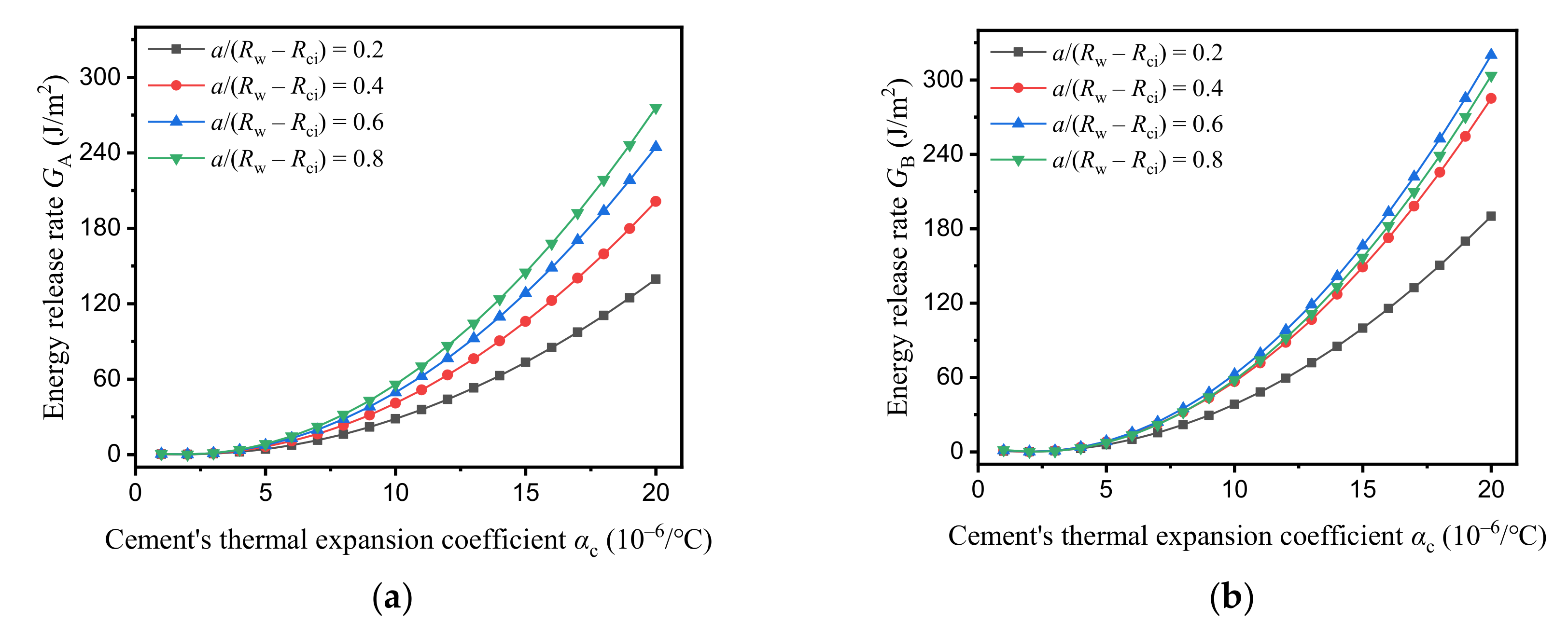
3.2. Radial Cracking

Radial cracking is another failure mode in cement during CO2 injection. Tensile hoop stresses are the driving forces for radial crack propagation. The pressure inside the casing and shrinkage owing to the temperature drop are the two leading causes of tensile hoop stresses in cement. Crack length is also a critical factor in crack extension. Considering these factors, we depict the variation of ERR at the radial crack tips with the mechanical and thermal properties of cement under different initial crack lengths. This initial defect size is normalized by the thickness of the cement sheath as a/(RwRci), where Rw and Rci are the radii of the borehole and the internal cement sheath, respectively. We study both ends of the radial crack and use A and B to represent the tips near and far from the casing-cement interface, respectively.
A higher Young’s modulus for cement would induce greater tensile hoop stresses, which would result in a larger ERR at both crack tips, as shown in Figure 8. When Ec/Ef = 0.2, the energy release rates are 18.5 J/m2 and 29.8 J/m2 at tip A and tip B, respectively, for a/(RwRci) = 0.4. As Ec/Ef increases to 0.8, GA and GB are augmented to 62.6 J/m2 and 78.8 J/m2, respectively, with the same crack length. The typical values for the resistance of cement is about −1 MPa × m−1/2 [26], which converted to energy release rates gives a range of approximately 60−1000 J/m2 (using Equation (4) and supposing that the cement’s Young’s modulus varies from 1 GPa to 15 GPa). Hence, stiffer cement types drive radial crack propagation.
It must be pointed out that the two tips of the radial crack present different variations of driving forces based on the initial defect size. For the tip near the casing-cement interface, longer cracks always produce higher ERR values. In Figure 8a, GA increases more linearly with Ec for longer cracks. However, the energy release rate at the crack tip far from the casing-cement interface exhibits a non-linear increase with the crack length in Figure 8b. The GB value is 63.0 J/m2 with a/(RwRci) = 0.6 and Ec/Ef = 0.5, while it is 58.5 J/m2 at a/(RwRci) = 0.8 with the same Young’s modulus of the cement. According to Equation (1), increasing the crack length or the applied stress will intensify the energy release rate. Previous studies [17,30] indicate that the tensile hoop stress in cement decreases as it departs from the casing-cement interface. Therefore, the reduction of ERR due to the hoop stress decrease overwhelms the enhancement effect caused by elongating crack lengths. A transverse comparison between Figure 8a,b shows that GA is smaller than GB in most cases. Only at a/(RwRci) = 0.8 is GA greater than GB when Ec/Ef > 0.6. The rigid bond between the casing and cement imposes a strong constraint when the radial crack extends to this interface. This constraint makes the part near the casing-cement interface more resistant to fracturing, which leads to GA being smaller than GB.
The ERR at the two crack tips becomes larger when the Poisson’s ratio of the cement increases, as plotted in Figure 9. The curves in Figure 9 are similar to the ones in Figure 5 for interfacial debonding. Higher values of for the Poisson’s ratio of the cement also induce greater tensile hoop stresses in the cement, which promote radial cracking. As νc reaches 0.35, GA and GB can increase up to 103.2 J/m2 and 100.0 J/m2, respectively, at a/(RwRci) = 0.8. Again, for crack tip B, the largest energy release rate occurs at a/(RwRci) = 0.6. It should be noted that the curves in Figure 9a separate at regular intervals, while the variations of ERR with νc at longer cracks (a/(RwRci) ≥ 0.4) are close to each other in Figure 9b. For example, when νc is 0.32, GB is 82.1 J/m2, 92.0 J/m2, and 86.8 J/m2 for a/(RwRci) = 0.4, 0.6, and 0.8, respectively.
Figure 10 illustrates the evolution of ERR with the cement’s thermal expansion coefficient for radial cracking. Large magnitudes of αc also accelerate radial crack propagation, similarly to interfacial debonding. More contractions would occur in cement with a high thermal expansion coefficient. As the cement sheath is constrained by the casing and formation, more shrinkage means more tensile stresses would be generated by the contraction. In particular, GA increases to 276.0 J/m2 as αc = 2 × 10⁻⁵/°C with a/(RwRci) = 0.8, while GB increases to more than 300 J/m2 with the same αc when a/(RwRci) ≥ 0.6. The effect of the thermal expansion coefficient of cement is the most influential factor in radical crack propagation among the parameters considered. Similarly, as a/(RwRci) ≥ 0.4, the energy release rates at tip B are approximate to each other.
Finally, we study the influence of cement’s thermal conductivity on radial cracking. Figure 11a shows that the ERR at crack tip A is insensitive to kc. GA changes very slowly with kc for all crack lengths. It only decreases by 1.2% when kc changes from 0.25 W/(m × °C) to 5 W/(m × °C) for a/(RwRci) = 0.2, while for a/(RwRci) = 0.8 it increases by 13.8%. The insensitivity of GA to kc is attributed to the very short distance from tip A to the casing-cement interface. Heat conduction over this short distance is very fast, which means the temperature at tip A close to the casing and nearly independent of the thermal conductivity of cement, whereas the variation of GB with kc is much more complicated. When a/(RwRci) = 0.2, GB increases gradually with kc and becomes stable. As a/(RwRci) ≥ 0.4, GB increases significantly with kc. Specifically, GB grows by 52.3% when kc varies from 0.25 W/(m × °C) to 5 W/(m × °C) for a/(RwRci) = 0.4. Unlike Figure 8b, Figure 9b, and Figure 10b, when kc is greater than 1 W/(m × °C), a longer crack always induces a lager ERR at crack tip B. As discussed in Section 3.1, cement with a higher thermal conductivity induces a more considerable temperature drop at crack tip B, which may lead to a larger tensile hoop stress propagating radial cracks.

4. Discussion

Our simulation indicates that the temperature fluctuation in the wellbore due to CO2 injection could pose risks for interfacial debonding and radial cracking. Further parametric studies show that adjusting the mechanical properties would mitigate these risks and maintain the cement’s integrity. It must be emphasized that the current simulation focuses on the influence of cement’s mechanical and thermal properties on the energy release rate of interfacial and radical cracks in wellbore components. The obtained results are limited by some primary assumptions, including elastic deformation, steady thermal conduction, and the negligible initial stress state in cement. Under these conditions, the effects of the considered parameters of cement on the ERR is in the order of: thermal expansion coefficient > Young’s modulus > Poisson’s ratio > the thermal conductivity. A cement high thermal expansion coefficient would increase the ERR of the interfacial and radial cracks to over 300 J/m2. Multiple factors can affect cement’s thermal expansion coefficient, including additives, the water-to-cement ratio, and the downhole temperature and pressure [38]. These parameters can change dramatically during the life of a well for CCS. The influence of cement’s thermal expansion coefficient on interfacial debonding and radial cracking is considerable. The energy release rate is relatively insensitive to cement’s thermal conductivity, as the thermal process is deemed to be in a steady state. Nevertheless, a transient heat transfer model is more responsive to thermal conductivity.
More precisely, the mechanical properties of cement have different impacts on interfacial debonding and radial cracking. The energy release rate of the interfacial crack is more sensitive to cement’s Poisson’s ratio than to its Young’s modulus. However, this is contrary to radial cracking. In practice, engineers frequently tune cement’s Young’s modulus. The current study suggests the use of soft cement to reduce the ERR at the cement-formation interface and to reduce radial cracking. This is consistent with the previous studies showing that soft cement could mitigate the stress state [17,37]. In particular, the benefits of soft cement are more significant with stiffer formations. Unfortunately, soft cement often has little resistance to tensile and shear compressive failure [28]. In the lower range of the Young’s modulus, softer cement could increase the energy release rate at the casing-cement interface (see Figure 4). This may add to the complex stress state near the interface. The requires extensive consideration to protect the cement sheath from different failure modes.
The geometry of the cracks is also an influential factor in ERR, as illustrated in Figure 3. Notably, the optimal situation is to avoid any defect, either inside the cement or at the interfaces, since the energy release rate of these cracks will increase with the defect size. In reality, the cement sheath will contain defects after setting and subsequent operations. Furthermore, the different behaviors of the two tips of the radial cracks illustrate that the crack position is vital to crack propagation in the wellbore. A crack near the interface is less likely to be extended than one far from the interface. This also indicates that rigid bonding between the casing and cement or between the cement and formation could inhibit radical cracking. Therefore, not only does the high quality of the bonding prevent interfacial failure, but it also reduces the risk of radial cracking. Enhancing the interfacial strength of the wellbore components is of paramount importance to well integrity.
Injection parameters such as the injection temperature, rate, and duration determine the boundary conditions for the simulation [29]. Generally, closing the temperature gap between the injected CO2 and the formation will reduce wellbore stresses [21,29]. The cost is a loss of the efficiency of the injection in CCS. In field applications, CO2 tends to be injected in a liquid state, which is more economical than injecting supercritical gaseous CO2 [29]. Finite element simulation of this scenario takes a sever situation as the boundary conditions, which makes the relevant results meaningful for practical injection activities.
Downhole conditions are critical parameters to the wellbore stress state and the propagation of cracks in barrier components. Recently, a study on well integrity during CO2 injection for CCS showed that the existence of in situ horizontal stresses is conducive to reducing the risk of cracking in cement by applying compressive stresses to the wellbore [29]. Section 2 does not take into account the effect of in situ stresses for the property assumption. As the formation is elastic, stress release on the hole would occur during drilling. Then, the stress state of the cement would be unaffected by in situ stresses. However, owing to the viscous behavior of the formation, in situ stresses could be applied to the well section near the hole gradually. Another issue is that the long-term injection of CO2 into reservoirs would increase in situ stresses, which may change the wellbore stress state. To illustrate the effects of in situ horizontal stresses, we conduct a finite element simulation for interfacial debonding with non-uniform in situ stresses as boundary conditions. In Figure 12, Sh and SH represent the minimum and maximum in situ horizontal stresses, respectively, while the result of zero in situ stress is also plotted as a reference case. During the simulation, SH is set to 10 MPa. From Figure 12, it is clear that whether in situ stresses would reduce the interfacial energy release rate or not would depend on the ratio of Sh to SH. For the casing-cement interface, when Sh/SH ≥ 0.8 in situ stresses could reduce the ERR (Figure 12a), while for the cement-formation interface the ratio should be greater than 0.6 (Figure 12b). On the contrary, increasing the non-uniformity of in situ stresses would accelerate interfacial debonding in the wellbore, which is different from the previous study [29]. Since non-uniform in situ stresses can induce shear stress components at interfaces, the energy release rate of mode II will increase, in turn increasing the total ERR (see Equation (3)). Engineers have to be careful with non-uniform in situ stresses in terms of the maintenance of well integrity. Moreover, non-uniform in situ stresses change the positions at which the ERR reaches a peak value. Radial cracking would be inhibited regardless of whether the in situ stresses are uniform or non-uniform, since they reduce the tensile hoop stress in cement.

5. Conclusions

This work has investigated the cement integrity impaired by interfacial debonding and radial cracking during CO2 injection. We carried out a parametric study to reveal the impact of cement’s mechanical and thermal properties on the energy release rate of interfacial and radial cracks using finite element simulations. The boundary conditions were set with typical wellbore configurations and injection parameters. The modeling assumptions included the elastic deformation of the well barrier materials, steady heat conduction between the well sections, plane strain conditions, and ignorance of the cement’s initial stress. The influences of the crack geometries and in situ stresses on interfacial debonding and radial cracking were also studied.
Our results indicated that the energy release rate of interfacial and radial cracks could surpass 100 J/m2 with realistic wellbore geometries and injection parameters. The effects of cement’s mechanical and thermal properties on crack propagation depended on the crack type. For interfacial debonding, the energy release rate presented a fluctuant variation as the crack length increased. Lowering the Young’s modulus of the cement, the Poisson’s ratio, the thermal expansion coefficient, and the thermal conductivity could reduce the ERR of the cement-formation interface, while the use of stiff cement with high thermal conductivity would help prevent interfacial debonding at the casing-cement interface. Under the provided conditions, the cement-formation interface always has a higher tendency for debonding than the casing-cement interface. Regarding the radial cracking, longer cracks would produce a greater ERR if the crack tip was near the casing-cement interface. The ERR at the crack tip near the cement-formation interface presented a non-monotonic increase with the crack length. All of the radial cracks—except the one at a/(RwRci) = 0.2, which incorporated the cement’s thermal conductivity—had lower ERRs as the four studied parameters decreased. Among the considered parameters, the cement’s thermal expansion coefficient was the most influential factor in ERR, while its thermal conductivity was the least influential one. Additionally, the existence of in situ stresses is not always beneficial to cement integrity. Severe non-uniform in situ horizontal stresses could undermine the interface integrity by increasing the interfacial energy release rate. These findings could help improve the security and efficiency of CCS projects.

Author Contributions

Conceptualization, X.D. and D.G.; methodology, H.D., Z.D., and Y.M.; validation, H.D., Z.D. and Y.M.; investigation, H.D. and X.D.; writing—original draft preparation, H.D., X.D., and Z.D.; writing—review and editing, X.D. All authors have read and agreed to the published version of the manuscript.

Funding

This research was funded by the National Key R&D Program of China (Grant No. 2018YFB0605502), the National Natural Science Foundation of China (Grant No. 11872378), and the Natural Science Foundation of Beijing (Grant No. 2182062).

Conflicts of Interest

The authors declare no conflict of interest.

Appendix A

Figure A1 shows the energy release rate at the casing-cement interface calculated using different element numbers. The curves nearly overlap with each other, which demonstrates the insensitivity of the simulation results to the element number.
Figure A1. Energy release rate estimated with different element numbers.
Energies 13 04589 g0a1

References

  1. Bui, M.; Adjiman, C.S.; Bardow, A.; Anthony, E.J.; Boston, A.; Brown, S.; Fennell, P.S.; Fuss, S.; Galindo, A.; Hackett, L.A.; et al. Carbon capture and storage (CCS): The way forward. Energy Environ. Sci. 2018, 11, 1062–1176. [Google Scholar] [CrossRef] [Green Version]
  2. Eide, L.I.; Batum, M.; Dixon, T.; Elamin, Z.; Graue, A.; Hagen, S.; Hovorka, S.; Nazarian, B.; Nøkleby, P.H.; Olsen, G.I.; et al. Enabling large-scale carbon capture, utilisation, and storage (CCUS) using offshore carbon dioxide (CO2) infrastructure developments—A review. Energies 2019, 12, 1945. [Google Scholar] [CrossRef] [Green Version]
  3. IEA Transforming Industry through CCUS. 2019. Available online: https://www.iea.org/reports/transforming-industry-through-ccus (accessed on 31 May 2019).
  4. Alcalde, J.; Flude, S.; Wilkinson, M.; Johnson, G.; Edlmann, K.; Bond, C.E.; Scott, V.; Smv, G.; Ogaya, X.; Haszeldine, R.S. Estimating geological CO2 storage security to deliver on climate mitigation. Nat. Commun. 2018, 9, 2201. [Google Scholar] [CrossRef]
  5. Bois, A.-P.; Vu, M.-H.; Ghabezloo, S.; Sulem, J.; Garnier, A.; Laudet, J.-B. Cement sheath integrity for CO2 storage—An integrated perspective. Energy Procedia 2013, 37, 5628–5641. [Google Scholar] [CrossRef] [Green Version]
  6. Lackey, G.; Vasylkivska, V.S.; Huerta, N.J.; King, S.; Dilmore, R.M. Managing well leakage risks at a geologic carbon storage site with many wells. Int. J. Greenh. Gas Control 2019, 88, 182–194. [Google Scholar] [CrossRef]
  7. Wu, Y.; Patel, H.; Salehi, S.; Mokhtari, M. Experimental and finite element modelling evaluation of cement integrity under diametric compression. J. Petrol. Sci. Eng. 2020, 188, 106844. [Google Scholar] [CrossRef]
  8. Lavrov, A.; Torsæter, M. Physics and Mechanics of Primary Well Cementing; Springer: Berlin/Heidelberg, Germany, 2016. [Google Scholar]
  9. Carroll, S.; Carey, J.W.; Dzombak, D.; Huerta, N.J.; Li, L.; Richard, T.; Um, W.; Walsh, S.D.C.; Zhang, L. Review: Role of chemistry, mechanics, and transport on well integrity in CO2 storage environments. Int. J. Greenh. Gas Control 2016, 49, 149–160. [Google Scholar] [CrossRef] [Green Version]
  10. Wang, W.; Taleghani, A.D. Three-dimensional analysis of cement sheath integrity around Wellbores. J. Petrol. Sci. Eng. 2014, 121, 38–51. [Google Scholar] [CrossRef]
  11. Todorovic, J.; Gawel, K.; Lavrov, A.; Torsæter, M. Integrity of downscaled well models subject to cooling. In SPE Bergen One Day Semina; Society of Petroleum Engineers: Grieghallen, Bergen, Norway, 2016. [Google Scholar]
  12. Albawi, A.; De Andrade, J.; Torsæter, M.; Opedal, N.; Stroisz, A.; Vrålstad, T. Experimental set-up for testing cement sheath integrity in Arctic wells. In Proceedings of the OTC Arctic Technology Conference, Houston, TX, USA, 10–12 February 2014. [Google Scholar]
  13. De Andrade, J.; Sangesland, S.; Todorovic, J.; Vrålstad, T. Cement sheath integrity during thermal cycling: A novel approach for experimental tests of cement systems. In Proceedings of the SPE Bergen One Day Seminar, Bergen, Norway, 22 April 2015. [Google Scholar]
  14. Carpenter, R.B.; Brady, J.L.; Blount, C.G. The effects of temperature and cement admixes on bond strength. J. Petrol. Technol. 1992, 44, 936–941. [Google Scholar] [CrossRef]
  15. Bois, A.-P.; Garnier, A.; Galdiolo, G.; Laudet, J.-B. Use of a mechanistic model to forecast cement-sheath integrity. SPE Drill. Complet. 2012, 27, 303–314. [Google Scholar] [CrossRef]
  16. Liu, K.; Gao, D.; Taleghani, A.D. Impact of casing eccentricity on cement sheath. Energies 2018, 11, 2557. [Google Scholar] [CrossRef] [Green Version]
  17. Thiercelin, M.J.; Dargaud, B.; Baret, J.F.; Rodriquez, W.J. Cement Design Based on Cement Mechanical Response. SPE Drill. Complet. 1998, 13, 266–273. [Google Scholar] [CrossRef]
  18. Wu, J.; Knauss, M.E. Casing temperature and stress analysis in steam-injection wells. In Proceedings of the International Oil & Gas Conference and Exhibition in China, Beijing, China, 5–7 December 2006. [Google Scholar]
  19. Zhang, L.; Yan, X.; Yang, X.; Zhao, X. Evaluation of wellbore integrity for HTHP gas wells under solid-temperature coupling using a new analytical model. J. Nat. Gas Sci. Eng. 2015, 25, 347–358. [Google Scholar] [CrossRef]
  20. Bois, A.-P.; Garnier, A.; Rodot, F.; Sain-Marc, J.; Aimard, N. How to prevent loss of zonal isolation through a comprehensive analysis of microannulus formation. SPE Drill. Complet. 2011, 26, 13–31. [Google Scholar] [CrossRef]
  21. Nygaard, R.; Salehi, S.; Weideman, B.; Lavoie, R.G. Effect of dynamic loading on wellbore leakage for the Wabamun area CO2-sequestration project. J. Can. Petrol. Technol. 2014, 53, 69–82. [Google Scholar] [CrossRef]
  22. Aursand, P.; Hammer, M.; Lavrov, A.; Lund, H.; Munkejord, S.T.; Torsæter, M. Well integrity for CO2 injection from ships: Simulation of the effect of flow and material parameters on thermal stresses. Int. J. Greenh. Gas Control 2017, 62, 130–141. [Google Scholar] [CrossRef] [Green Version]
  23. Kiran, R.; Teodoriu, C.; Dadmohammadi, Y.; Nygaard, R.; Wood, D.; Mokhtari, M.; Salehi, S. Identification and evaluation of well integrity and causes of failure of well integrity barriers (A review). J. Nat. Gas Sci. Eng. 2017, 45, 511–526. [Google Scholar] [CrossRef]
  24. Anderson, T.L. Fracture Mechanics: Fundamentals and Applications, 3rd ed; Taylor Francis: Milton Park, UK, 2005. [Google Scholar]
  25. Petersen, T.A.; Ulm, F.-J. Radial fracture in a three-phase composite: Application to wellbore cement liners at early ages. Eng. Fract. Mech. 2016, 154, 272–287. [Google Scholar] [CrossRef] [Green Version]
  26. Dong, X.; Duan, Z.; Qu, Z.; Gao, D. Failure analysis for the cement with radial cracking in HPHT wells based on stress intensity factors. J. Petrol. Sci. Eng. 2019, 179, 558–564. [Google Scholar] [CrossRef]
  27. Wang, Z.; Lou, Y.; Suo, Z. Crack tunneling in cement sheath of hydrocarbon well. J. Appl. Mech. 2016, 83, 011002. [Google Scholar] [CrossRef] [Green Version]
  28. Andrade, J.D.; Sangesland, S. Cement sheath failure mechanisms: Numerical estimates to design for long-term well integrity. J. Petrol. Sci. Eng. 2016, 147, 682–698. [Google Scholar] [CrossRef]
  29. Roy, P.; Morris, J.P.; Walsh, S.D.C.; Iyer, J.; Carroll, S. Effect of thermal stress on wellbore integrity during CO2 injection. Int. J. Greenh. Gas Control 2018, 77, 14–26. [Google Scholar] [CrossRef]
  30. Dong, X.; Duan, Z.; Gao, D. Assessment on the cement integrity of CO2 injection wells through a wellbore flow model and stress analysis. J. Nat. Gas Sci. Eng. 2020, 74, 103097. [Google Scholar] [CrossRef]
  31. Hutchinson, J.W.; Suo, Z. Mixed Mode Cracking in Layered Materials. Adv. Appl. Mech. 1991, 29, 63–191. [Google Scholar]
  32. Xie, D.; Biggers, S.B. Progressive crack growth analysis using interface element based on the virtual crack closure technique. Finite Elem. Anal. Des. 2006, 42, 977–984. [Google Scholar] [CrossRef]
  33. Bachu, S.; Shaw, J.C.; Pearson, R.M. Estimation of oil recovery and CO2 storage capacity in CO2 EOR incorporating the effect of underlying aquifers. In Proceedings of the SPE/DOE Symposium on Improved Oil Recovery, Tulsa, OK, USA, 17–21 April 2004. [Google Scholar]
  34. Hwang, J.; Ahmed, R.; Tale, S.; Shah, S. Shear bond strength of oil well cement in carbonic acid environment. J. CO2 Util. 2018, 27, 60–72. [Google Scholar] [CrossRef]
  35. Tabatabaei, M.; Taleghani, A.D.; Alem, N. Measurement of mixed mode interfacial strengths with cementitious materials. Eng. Fract. Mech. 2020, 223, 106739. [Google Scholar] [CrossRef]
  36. Lin, Y.; Karadelis, J.N. Interfacial fracture toughness of composite concrete beams. Constr. Build. Mater. 2019, 213, 413–423. [Google Scholar] [CrossRef]
  37. Lavrov, A. Stiff cement, soft cement: Nonlinearity, arching effect, hysteresis, and irreversibility in CO2-well integrity and near-well geomechanics. Int. J. Greenh. Gas Control 2018, 70, 236–242. [Google Scholar] [CrossRef]
  38. Loiseau, A. Thermal expansion of cement and well integrity of heavy oil wells. In Proceedings of the SPE Heavy and Extra Heavy Oil Conference: Latin America, Medellín, Colombia, 24–26 September 2014. [Google Scholar]
Figure 1. The schematic of a vertical injection well with defects in the wellbore barriers: (a) the vertical wellbore; (b) a radial crack in the cement; (c) an arc crack at the casing-cement interface; (d) an arc crack at the cement-formation interface.
Energies 13 04589 g001
Figure 2. The meshes of the interfacial and radial cracks in the simulation: (a) the bonded nodes marked in red at the casing-cement interface; (b) the bonded nodes marked in red at the cement-formation interface; (c) the radial crack meshed with the refined mesh.
Energies 13 04589 g002
Figure 3. The energy release rate at the interfaces as a function of the central angle of the crack.
Energies 13 04589 g003
Figure 4. Variation of the energy release rates for interfacial debonding with the Young’s modulus of cement.
Energies 13 04589 g004
Figure 5. Effect of cement’s Poisson’s ratio on interfacial debonding.
Energies 13 04589 g005
Figure 6. Evolution of the energy release rate at interfaces with cement’s thermal expansion coefficient.
Energies 13 04589 g006
Figure 7. Effect of cement’s thermal conductivity on the interfacial debonding.
Energies 13 04589 g007
Figure 8. Energy release rate of a radial crack in cement as a function of the cement’s Young’s modulus: (a) crack tip A; (b) crack tip B.
Energies 13 04589 g008
Figure 9. Effect of cement’s Poisson’s ratio on radial cracking: (a) crack tip A and (b) the crack tip B.
Energies 13 04589 g009
Figure 10. Evolution of the energy release rate at the radial crack tips with due to the thermal expansion coefficient of the cement: (a) crack tip A; (b) crack tip B.
Energies 13 04589 g010
Figure 11. Evolution of the energy release rate at the radial crack tips with cement’s thermal expansion coefficient: (a) crack tip A; (b) crack tip B.
Energies 13 04589 g011
Figure 12. Impacts of in situ horizontal stresses on interfacial debonding: (a) crack at the casing-cement interface; (b) crack at the cement-formation interface.
Energies 13 04589 g012
Table 1. The geometrical parameters and mechanical and thermal properties of wellbore components for a reference state.
ParameterCasingCementFormation
Inner radius (mm)60.6869.85107.95
Outer radius (mm)69.85107.961000
Young’s modulus (GPa)2001020
Poisson’s ratio0.30.230.2
Thermal expansion coefficient (10−6/°C)121011
Thermal conductivity (w/(m × °C))470.522

