Abstract
The efficiencies of the Organic Rankine Cycle (ORC) are not very high and only very seldom do they exceed 20%. The increase and optimization of initial parameters and certain modifications of the thermodynamic cycle make it possible to overcome these drawbacks. A new modified cycle has been described and analyzed in detail in the paper. Similarly to the Ericsson cycle for gas turbines, isothermal expansion in the turbine is suggested for the power plant with organic media. The new cycle and the typical ORC power plants have the same block diagram. The only difference is that expansion in the proposed cycle occurs not adiabatically but as an isothermal process. The thermodynamic calculations have been carried out for 11 various fluids and 4 different cycles. The obtained results have clearly shown that cycles with isothermal expansion (isothermal turbines) are characterized by remarkably higher efficiency than typical power plants with adiabatic turbines. The increase in efficiency varies from 6 to 12 percent points for cycles with saturated live vapor and from 4 to 7 percent points for cycles with superheated live vapor. The performed analyses have shown that it is possible to achieve a very high efficiency (over 45%) of organic cycle, which is a very competitive value. In such cases the proposed power plants can achieve an efficiency which is higher than that of modern steam turbine plants with supercritical parameters.
1. Introduction
The European power system will face a number of changes due to climate restrictions. This is imposed by emission standards mainly for carbon dioxide [1,2]. The activities of the European Union are focused on reducing electricity consumption, increasing the efficiency of energy conversion, and increasing the share of renewable energy in the energy production process [3]. Systems with steam turbines operating on supercritical and ultra-supercritical parameters are developing very intensively [4,5], as are combined gas-steam systems [6,7]. Moving away from carbon applications, new units are being introduced using a variety of biomass and biogas fuels [8,9,10]. At present, in distributed energy systems the technology of steam and gas microturbines is being applied and although the efficiency is still relatively low, the research is being carried out intensively [11,12,13]. As a rule, microturbine sets, working in distributed systems, use biomass as a source that fits in perfectly with the current trends [14]. The microturbine sets are equipped with neodymium electricity generators [15] as well as appropriate automation and control systems [16,17], which enable operation at partial load [18]. In the case of Organic Rankine Cycles the organic low-boiling media are applied [19,20,21]. If the expansion in the turbine ends in the zone of superheated vapor, the typical ORC power plant consists of a turbine, an electric generator, a condenser (low temperature heat exchanger), a pump, a vapor generator (high temperature heat exchanger), and an additional heat exchanger (the so-called “regenerator”, in order to use the heat of superheating for warming up the working liquid between the condenser and the boiler, Figure 1).
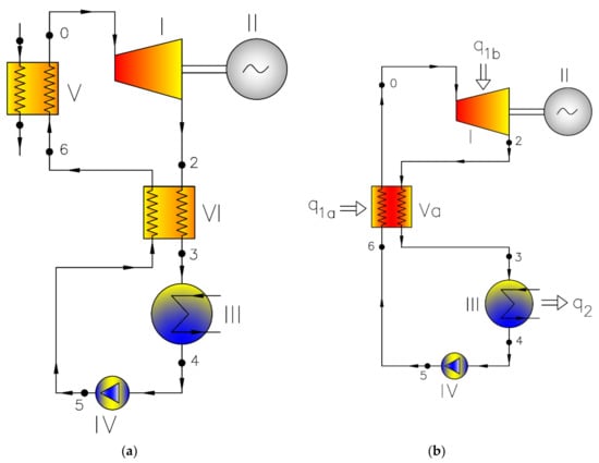
Figure 1.
Standard Organic Rankine Cycle (ORC) cycle for wet fluids (a) and cycle with modified vapor generator and isothermal expansion (b); where: I—turbine, II—generator, III—condenser, IV—main pump, V—vapor generator, Va—regenerator and vapor generator, VI—regenerator, q1a—heat delivered in vapor generator, q1b—heat delivered during isothermal expansion, q2—heat rejected with the water cooling condenser.
The ORC plants are very often supplied with sources of heat of rather low temperatures, for example, waste heat [22,23], geothermal energy [24], heat emitted from engines [25], gas turbines [26], and industrial processes [27,28] or agricultural and domestic waste. The Organic Rankine Cycle power plants achieve low efficiency, which exceeds 10% but only seldom reaches higher values (about 20%) [29].
The efficiency of power plants can be higher if we increase upper temperature and modify the cycles [30], making them more complex and applying additional elements [31]. As in the case of steam power plants, there are ways to increase efficiency by using inter-stage superheating in the steam generator [32], regenerative heating [33], or supercritical parameters [34]. We can also try to increase the efficiency of particular elements of power plants, though we may come across certain barriers, such as technological, material, or strength constraints. We cannot apply very low values of the lower cycle temperature due to the surrounding conditions, nor can we increase the upper temperature because of material limitations. It appears that the efficiencies of particular cycle elements are extremely high and it is very difficult to expect remarkable progress in that field. If, for example, we consider the most advanced ultra-supercritical steam power plants in design or operation, we usually find two interstage superheaters, a number of feedwater heaters (including the heater for supercritical parameters), live steam temperature as high as 760 °C, and live steam pressure of about 35 MPa, which can be treated as limit values for those parameters today. We observe a very impressive growth of the efficiency of power plant elements: turbines (up to 95% or more for medium pressure steam turbines), pumps (up to 85%), electric generators (up to 99%+), or steam boilers (up to 95%). The efficiency of gas turbines (max. 44%+) and the efficiency of combined gas-steam power (above 62%) are considered to be extremely high values. We are still trying to find a better solution; for example, intensive efforts are being made to develop nuclear power plants with reactors of new types or power plants with high parameters and other working media such as supercritical CO2 cycles.
According to our analysis there exists one more solution: a new thermodynamic cycle of remarkably higher efficiency. First, let us consider the situation in gas turbine engines. They work according to the Brayton cycle (cycle A-B-C-D-A in Figure 2) or the Brayton cycle with modifications (regenerator, intercooling, sequential combustion). In the ideal case, when an infinite number of intercoolers, an infinite number of sequential combustion chambers, and 100%-effective regeneration are considered, the so-called Ericsson cycle is obtained. Its interpretation in the temperature-entropy diagram is presented in Figure 2. In this cycle, the heat is added during the isothermal expansion 3–4 and heat is rejected during the isothermal compression 1–2. In the perfect regenerator, the temperature of the medium during the isobaric process 2–3 increases due to the heat delivered by the hot gases whose temperature decreases during the isobaric process 4–1.
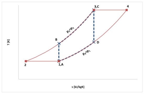
Figure 2.
Comparison of Brayton cycle (dotted blue line) and Ericsson cycle (red line) (interpretations in T-s diagram).
The efficiency of the Ericsson cycle is equal to the efficiency of the Carnot cycle between the upper temperature T3 and the lower temperature T1. Similar cycle is proposed for organic media as working fluids. The block diagram of this cycle is exactly the same as in ORC power plants while the only difference is that expansion in the turbine occurs not adiabatically but as an isothermal process.
The authors have proposed a new cycle for vapor power plants which increases the efficiency in the same temperature range by several percent points (from 4 to 12 percent points in the considered variants). The most important innovation here is that a new turbine of isothermal type is applied in the cycles. The performed analyses have proved that it is possible to build organic power plants whose efficiency is competitive with modern supercritical steam turbine plants. These types of power plants have not been described in the literature so far.
2. Modelling
The block diagram is identical for all the analyzed power plants. However, the cycles vary in the function of the regenerator and in the type of expansion in the turbine. When saturated dry vapor is generated in a boiler, the regenerator is used only for warming up the working fluid, whereas when superheated live vapor is produced, the regenerator is used for warming up, vaporization, and partial superheating of the working fluid.
Thus, the analysis includes 2 variants of thermodynamic cycles with different functions of the regenerator:
- Variant 1: cycle with saturated live vapor and the regenerator for warming up the working fluid;
- Variant 2: cycle with superheated live vapor and the regenerator for warming up, vaporization, and partial superheating of the working fluid.
Each cycle has been calculated assuming the adiabatic (AD) and isothermal (IZT) expansions in the turbine, thus 4 cases of the cycle have been analyzed for each working medium.
When choosing the working media, the most important features were taken into account, such as low toxicity, chemical stability, low potential for decomposition, and low flammability [19]. The following media have been included in the analysis:
- Acetone (chemical formula—C11H24, commercial name—acetone, [35]);
- Octamethylcyclotetrasiloxane (chemical formula—C8H24O4Si4, commercial name—D4, [36]);
- Dodecamethylcyclohexasiloxane (chemical formula—C12H36O6Si6, commercial name—D6, [36]);
- Octamethyltrisiloxane (chemical formula—C8H24O2Si3, commercial name—MDM, [36]);
- Hexamethyldisiloxane (chemical formula—C6H18OSi2, commercial name—MM, [36]);
- 1,1,1,3,3-pentafluoropropane (chemical formula—C3H3F5, commercial name—R245fa, [36]);
- 1,1,1,3,3-pentafluorobutane (chemical formula—C4H5F5, commercial name—R365mfc, [36]);
- Methylcyclohexane (chemical formula—C7H14, commercial name—c1cc6, [36]);
- N-propylcyclohexane (chemical formula—C9H18, commercial name—c3cc6, [36]);
- Undecane (chemical formula—C11H24, commercial name—C11, [36]);
- 1-chloro-3,3,3-trifluoroprop-1-ene (chemical formula—C3H2ClF3, commercial name—R1233zd, [37]).
The calculations have been performed assuming upper and lower parameters of the working medium. Standard thermodynamics formulae have been used, occasionally applying the iteration method (when values of specific heat, which depend on other thermodynamic parameters, have been calculated).
The thermodynamic calculations have been carried out for 11 various fluids and 4 different cycles. The values of initial pressure and temperature have been determined, taking into account particular schema of the cycle. For the calculations of the cycles according to subcritical variant 1 (cycle with saturated live vapor and a regenerator for warming up the working fluid), the saturation temperature in the vapor generator was assumed to be 20 °C lower than the critical temperature for a particular medium (in order to make sure that the process of vaporization takes place and that the expansion in the turbine is realized in superheated vapor region). Consequently, the initial pressure was read as the saturation pressure for that temperature. The parameters of the working media have been determined using the REFPROP [38] media library. For all the calculated examples of variant 1 the initial temperature and pressure are shown in Table 1.

Table 1.
Initial temperatures and pressures for different working media for cycle variant 1 (cycle with saturated live vapor and a regenerator for warming up the working fluid).
For the calculations of the cycles according to variant 2 (cycle with superheated live vapor and the regenerator for warming up, vaporization, and partial superheating of the working fluid) the values of initial pressure and temperature have been determined taking into account the media stability limitation and the maximum value of the cycle efficiency. The problem of the stability of organic media is quite complicated and uncertain. There is a lack of proper experimental data and hardly any recommendations. The mechanism of chemical decomposition of the compounds has not been sufficiently investigated and described. The medium can lose its stability in a given temperature and become stable again when the temperature increases. In practice, it is the amount of the decomposed media that plays an important role during power plant operation. From time to time, the installation is refilled with some amount of new media, so minor decomposition is not treated as a problem. The latest literature provides access to information on the latest scientific research on the analysis of working media at high temperatures and pressures, e.g., for MDM [39], MM [40], c1cc6 [41], n-dodecane [42], R134a [43], n-decane [44], R152, R236fa [45], R245fa [46], or titanium tetrachloride [47]. However, there are still no more detailed analyses of operating media for power plants. To be on the safe side, a margin of 50 °C below the maximum temperature given in the REFPROP library was assumed. For all the calculated examples of variant 2 the initial temperature and pressure are shown in Table 2.
Table 2.
Initial temperatures and pressures for different working media for cycle variant 2 (cycle with superheated live vapor and a regenerator for warming up, vaporization and partial superheating of the working fluid).
The pressure in the condenser has been estimated assuming the temperature of the cooling water to be 15 °C, but no lower than 3 kPa. The efficiencies of particular elements (typical of micro power plants) are shown in Table 3 [19,21,48].
Table 3.
Assumed values of the efficiencies of particular cycle elements.
3. Results and Discussion
The interpretation of the two variants of the thermodynamic cycles for the adiabatic and isothermal expansion in the turbine are presented in Figure 3 and Figure 4. As an example of the working medium the C11H24 (undecane C11) has been chosen.
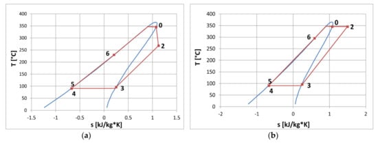
Figure 3.
Interpretation of Variant 1 for adiabatic (a) and isothermal (b) expansion (working medium: undecane-C11); where: limit line—red and cycle—blue line.
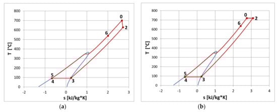
Figure 4.
Interpretation of Variant 2 for adiabatic (a) and isothermal (b) expansion (working medium: undecane-C11); where: limit line—red and cycle—blue line.
The comparison of overall efficiency (the relation between the electric output to the heat delivered to the power plant) for different working media for adiabatic and isothermal expansions is presented in Figure 5 and Figure 6, for variant 1 and variant 2, respectively.
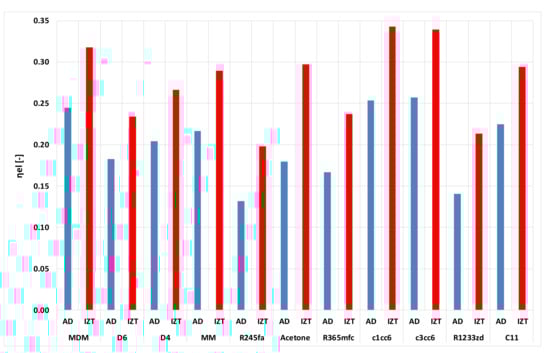
Figure 5.
Variant 1—overall efficiency for adiabatic and isothermal expansions (red bars—isothermal expansion, blue bars—adiabatic expansion).
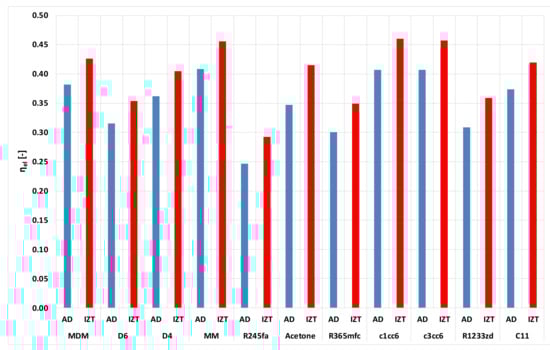
Figure 6.
Variant 2—overall efficiency for adiabatic and isothermal expansions (red bars—isothermal expansion, blue bars—adiabatic expansion).
In the case of variant 1, with adiabatic expansion in the turbine, the smallest efficiency was obtained for R245fa (13%) and for r1233zd (14%), while the highest value of about 26% were calculated for c1cc6. For isothermal expansion, the smallest efficiency was also for R245fa (20%) and for r1233zd (22%), while the highest value of about 35% was estimated for c1cc6. Of course, in every case the efficiency of the cycle with isothermal expansion was remarkably higher than the efficiency of the cycle with adiabatic expansion. The increase in efficiency varied from 5 percent points for D6 and up to 12 percent points for acetone.
In the case of variant 2 with adiabatic expansion in the turbine, the smallest efficiency was obtained for R245fa (25%) while the highest values of about 41% were calculated for MM, c1cc6, and c3cc6. For isothermal expansion the smallest efficiency was also for R245fa (29%), while the highest values of about 47% were estimated for c1cc6 and c3cc6, and about 46% for MM. Of course, in every analyzed case the efficiency of the cycle with isothermal expansion was higher than the efficiency of the cycle with adiabatic expansion. The increase in the efficiency varied from 4 to 7 percent points.
From the above calculations it follows that the cycles with isothermal expansion (isothermal turbines) are characterized by remarkably higher efficiency than typical power plants with adiabatic turbine. Heat q1b is added to the working medium during its flow in the turbine. In this way we realize the expansion at a constant temperature, and at the same time we increase the average value of the temperature delivering heat to the cycle. The rise in the average upper temperature leads to the increase in cycle efficiency. Calculations of heat q1b have been performed with the use of standard approach:
where T—temperature, s—specific entropy, and q—specific heat.
For all the considered variants, heat q1b equaled from 37.56% to 56.33% of the whole heat delivered in the cycle (Table 4).
Table 4.
Heat delivered during isothermal expansion (q1b) in relation to the total heat supplied in Table 1 and variant 2.
4. Conclusions
The authors have proposed a new cycle for vapor power plants and have performed an analysis proving that it is possible to increase power plant efficiency in the same temperature range by several percent points. The increase in the efficiency varies from 5 to 12 percent points for cycles with saturated live vapor, and from 4 to 7 percent points for cycles with superheated live vapor, which is a very impressive result. Nowadays, in the case of large output advanced gas turbine units, a one point increase in efficiency costs millions of dollars and years of intensive research.
At present, only very simple ORC turbine power plants have been applied and described in the literature (Figure 1). As a rule, in these turbines adiabatic expansion of the working media takes place in order to generate power. The temperature of live vapor in these solutions is relatively low (lower than 300 °C). The presented analyses have been performed for higher values of temperature (even 700 °C) and for higher values of the initial pressure. However, the most important innovation is that instead of a classical approach with an adiabatic turbine, a new turbine of isothermal type is applied in the cycles. These types of power plants with organic media have not been discussed in the literature so far.
The performed analyses clearly have proved that it is possible to build organic power plants of relatively high efficiency (over 45%), which is a very competitive value. In such cases the proposed power plants can achieve an efficiency which is higher than that of modern steam turbine plants with supercritical parameters. It is also very important to underline that the organic power plants with isothermal turbines are cheaper and much simpler than modern supercritical steam power plants of large output working within the same range of design parameters.
So far, no power plant with isothermal turbines has been constructed in the world but our team has successfully designed, built, and tested an experimental isothermal turbine which will soon be described in a separate paper (Figure 7 shows the experimental variant of a gas turbine working according to the Ericsson cycle). Thus, the obtained results of the presented analysis can be considered for future applications.
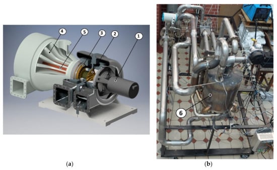
Figure 7.
The example of the experimental variant of a gas turbine working according to the Ericsson cycle (a), turboset research stand with isothermal expansion (b), where: 1—electric generator, 2—compressor, 3—turbine rotor, 4—expansion nozzle, 5—burner, 6—built-up turboset.
Author Contributions
Conceptualization, K.K. and M.P.; methodology, K.K. and M.P.; formal analysis K.K. and M.P.; data curation, K.K. and M.P.; writing—original draft preparation, K.K. and M.P.; writing—review and editing, K.K. and M.P.; supervision, K.K. and M.P.; funding acquisition, K.K. and M.P. All authors have read and agreed to the published version of the manuscript.
Funding
This research received no external funding.
Conflicts of Interest
The authors declare no conflict of interest. The funders had no role in the design of the study; in the collection, analyses, or interpretation of data; in the writing of the manuscript, and in the decision to publish the results.
References
- Kamiński, J.; KudeŁko, M. The prospects for hard coal as a fuel for the Polish power sector. Energy Policy 2010, 38, 7939–7950. [Google Scholar] [CrossRef]
- Szczerbowski, R.; Ceran, B. Development perspectives of the Polish power generation sector according to the climate preservation conference COP21 policies. E3S Web Conf. 2017, 14, 01003. [Google Scholar] [CrossRef]
- Badami, M.; Chicco, G.; Portoraro, A.; Romaniello, M. Micro-multigeneration prospects for residential applications in Italy. Energy Convers. Manag. 2018, 166, 23–36. [Google Scholar] [CrossRef]
- Piwowarski, M. Optimization of steam cycles with respect to supercritical parameters. Pol. Marit. Res. 2009, S1, 45–51. [Google Scholar] [CrossRef][Green Version]
- Tumanovskii, A.G.; Shvarts, A.L.; Somova, E.V.; Verbovetskii, E.K.; Avrutskii, G.D.; Ermakova, S.V.; Kalugin, R.N.; Lazarev, M.V. Review of the coal-fired, over-supercritical and ultra-supercritical steam power plants. Therm. Eng. 2017, 64, 83–96. [Google Scholar] [CrossRef]
- Maheshwari, M.; Singh, O. Thermodynamic study of different configurations of gas-steam combined cycles employing intercooling and different means of cooling in topping cycle. Appl. Therm. Eng. 2019, 162, 114249. [Google Scholar] [CrossRef]
- Piwowarski, M.; Kosowski, K. Design analysis of combined gas-vapour micro power plant with 30 kW air turbine. Pol. J. Environ. Stud. 2014, 23, 1397–1401. [Google Scholar]
- Kosowski, K.; Tucki, K.; Piwowarski, M.; Stępień, R.; Orynycz, O.; Włodarski, W. Thermodynamic Cycle Concepts for High-Efficiency Power Plants. Part B: Prosumer and Distributed Power Industry. Sustainability 2019, 11, 2647. [Google Scholar] [CrossRef]
- Duvia, A.; Gaia, M. ORC Plants for Power Production from Biomas from 0.4MWe to 1.5MWe: Technology, Efficiency, Practical Experiences and Economy. In Proceedings of the 7th Holzenergie Symopsium, Zurich, Switzerland, 18 October 2002. [Google Scholar]
- Mikielewicz, D.; Kosowski, K.; Tucki, K.; Piwowarski, M.; Stępień, R.; Orynycz, O.; Włodarski, W. Influence of Different Biofuels on the Efficiency of Gas Turbine Cycles for Prosumer and Distributed Energy Power Plants. Energies 2019, 12, 3173. [Google Scholar] [CrossRef]
- Mikielewicz, D.; Kosowski, K.; Tucki, K.; Piwowarski, M.; Stępień, R.; Orynycz, O.; Włodarski, W. Gas Turbine Cycle with External Combustion Chamber for Prosumer and Distributed Energy Systems. Energies 2019, 12, 3501. [Google Scholar] [CrossRef]
- Kosowski, K.; Włodarski, W.; Piwowarski, M.; Stępień, R. Performance characteristics of a micro-turbine. Adv. Vib. Eng. 2014, 2, 341–350. [Google Scholar]
- Kosowski, K.; Stępień, R.; Włodarski, W.; Piwowarski, M.; Hirt, Ł. Partial admission stages of high efficiency for a microturbine. J. Vib. Eng. Technol. 2014, 2, 441–448. [Google Scholar]
- Corrêa, P.S.P.; Zhang, J.; Lora, E.E.S.; Andrade, R.V.; De Mello e Pinto, L.R.; Ratner, A. Experimental study on applying biomass-derived syngas in a microturbine. Appl. Therm. Eng. 2019, 146, 328–337. [Google Scholar] [CrossRef]
- Włodarski, W. Experimental investigations and simulations of the microturbine unit with permanent magnet generator. Energy 2018, 158, 59–71. [Google Scholar] [CrossRef]
- Włodarski, W. Control of a vapour microturbine set in cogeneration applications. ISA Trans. 2019, 94, 276–293. [Google Scholar] [CrossRef]
- Włodarski, W. A model development and experimental verification for a vapour microturbine with a permanent magnet synchronous generator. Appl. Energy 2019, 252, 113430. [Google Scholar] [CrossRef]
- Thu, K.; Saha, B.B.; Chua, K.; Bui, T.D. Thermodynamic analysis on the part-load performance of a microturbine system for micro/mini-CHP applications. Appl. Energy 2016, 178, 600–608. [Google Scholar] [CrossRef]
- Quoilin, S.; Lemort, V. Technological and Economical Survey of Organic Rankine Cycle Systems. In Proceedings of the 5th European Conference Economics and Management of Energy in Industry, Vilamoura, Algavre, Portugal, 14–17 April 2009. [Google Scholar]
- Kosowski, K.; Piwowarski, M.; Stepien, R.; Włodarski, W. Design and investigations of the ethanol microturbine. Arch. Thermodyn. 2018, 39, 41–54. [Google Scholar] [CrossRef]
- Landelle, A.; Tauveron, N.; Haberschill, P.; Revellin, R.; Colasson, S. Organic Rankine cycle design and performance comparison based on experimental database. Appl. Energy 2017, 204, 1172–1187. [Google Scholar] [CrossRef]
- Quoilin, S.; Declaye, S.; Tchanche, B.F.; Lemort, V. Thermo-economic optimization of waste heat recovery Organic Rankine Cycles. Appl. Therm. Eng. 2011, 31, 2885–2893. [Google Scholar] [CrossRef]
- Lecompte, S.; Huisseune, H.; Van den Broek, M.; Vanslambrouck, B.; De Paepe, M. Review of organic Rankine cycle (ORC) architectures for waste heat recovery. Renew. Sustain. Energy Rev. 2015, 47, 448–461. [Google Scholar] [CrossRef]
- Altun, A.; Kilic, M. Thermodynamic performance evaluation of a geothermal ORC power plant. Renew. Energy 2020, 148, 261–274. [Google Scholar] [CrossRef]
- Da Silva, J.A.M.; Seifert, V.; De Morais, V.O.; Tsolakis, A.; Herreros, J.; Torres, E. Exergy evaluation and ORC use as an alternative for efficiency improvement in a CI-engine power plant. Sustain. Energy Technol. Assess. 2018, 30, 216–223. [Google Scholar] [CrossRef]
- Li, T.; Meng, N.; Liu, J.; Zhu, J.; Kong, X. Thermodynamic and economic evaluation of the organic Rankine cycle (ORC) and two-stage series organic Rankine cycle (TSORC) for flue gas heat recovery. Energy Convers. Manag. 2019, 183, 816–829. [Google Scholar] [CrossRef]
- Zhao, Y.; Liu, G.; Li, L.; Yang, Q.; Tang, B.; Liu, Y. Expansion devices for organic Rankine cycle (ORC) using in low temperature heat recovery: A review. Energy Convers. Manag. 2019, 199, 111944. [Google Scholar] [CrossRef]
- Kermani, M.; Wallerand, A.S.; Kantor, I.D.; Wang, L. Generic superstructure synthesis of organic Rankine cycles for waste heat recovery in industrial processes. Appl. Energy 2018, 212, 1203–1225. [Google Scholar] [CrossRef]
- Tchanche, B.F.; Lambrinos, G.; Frangoudakis, A.; Papadakis, G. Low-grade heat conversion into power using organic Rankine cycles—A review of various applications. Renew. Sustain. Energy Rev. 2011, 15, 3963–3979. [Google Scholar] [CrossRef]
- Vescovo, R.; Spagnoli, E. High Temperature ORC Systems. Energy Procedia 2017, 129, 82–89. [Google Scholar] [CrossRef]
- Piwowarski, M.; Kosowski, K. Advanced Turbine Cycles with Organic Media. Energies 2020, 13, 1327. [Google Scholar] [CrossRef]
- Braimakis, K.; Karellas, S. Energetic optimization of regenerative Organic Rankine Cycle (ORC) configurations. Energy Convers. Manag. 2018, 159, 353–370. [Google Scholar] [CrossRef]
- Abam, F.I.; Ekwe, E.; Effiom, S.; Ndukwu, M.; Briggs, T.; Kadurumba, C. Optimum exergetic performance parameters and thermo-sustainability indicators of low-temperature modified organic Rankine cycles (ORCs). Sustain. Energy Technol. Assess. 2018, 30, 91–104. [Google Scholar] [CrossRef]
- Mikielewicz, J.; Mikielewicz, D. Comparative study of selected fluids for use in supercritical Organic Rankine Cycles. Arch. Thermodyn. 2009, 30, 3–15. [Google Scholar]
- Set of Product’s Card of Chempur Poland Ltd. Available online: http://en.chempur.pl (accessed on 25 February 2020).
- Set of Product’s Card of Sigma-Aldrich Ltd. Available online: https://www.sigmaaldrich.com (accessed on 25 February 2020).
- Set of Product’s Card of SCHIESSL Poland Ltd. Available online: https://www.schiessl.pl/en (accessed on 25 February 2020).
- Lemmon, E.; Huber, M.; McLinden, M. NIST Standard Reference Database 23: Reference Fluid Thermodynamic and Transport Properties-REFPROP, Version 9.0 Edition; Standard Reference Data Program; National Institute of Standards and Technology: Gaithersburg, MD, USA, 2010. [Google Scholar]
- Keulen, L.; Landolina, C.; Spinelli, A.; Iora, P.; Manzolini, G.; Lietti, L.; Guardone, A. Design and commissioning of a thermal stability test-rig for mixtures as working fluids for ORC applications. Energy Procedia 2017, 129, 176–183. [Google Scholar] [CrossRef][Green Version]
- Xu, G.; Fu, J.; Quan, Y.; Wen, J.; Dong, B. Experimental investigation on heat transfer characteristics of hexamethyldisiloxane (MM) at supercritical pressures for medium/high temperature ORC applications. Int. J. Heat Mass Transf. 2020, 156, 119852. [Google Scholar] [CrossRef]
- Bounaceur, R.; Burklé-Vitzthum, V.; Marquaire, P.-M.; Fusetti, L. Mechanistic modeling of the thermal cracking of methylcyclohexane near atmospheric pressure, from 523 to 1273K: Identification of aromatization pathways. J. Anal. Appl. Pyrolysis 2013, 103, 240–254. [Google Scholar] [CrossRef]
- Herbinet, O.; Marquaire, P.-M.; Battin-Leclerc, F.; Fournet, R. Thermal decomposition of n-dodecane: Experiments and kinetic modeling. J. Anal. Appl. Pyrolysis 2007, 78, 419–429. [Google Scholar] [CrossRef]
- Invernizzi, C.M.; Iora, P.; Preißinger, M.; Manzolini, G. HFOs as substitute for R-134a as working fluids in ORC power plants: A thermodynamic assessment and thermal stability analysis. Appl. Therm. Eng. 2016, 103, 790–797. [Google Scholar] [CrossRef]
- Wang, Y.; Zhao, Y.; Liang, C.; Chen, Y.; Zhang, Q.; Li, X. Molecular-level modeling investigation of n-decane pyrolysis at high temperature. J. Anal. Appl. Pyrolysis 2017, 128, 412–422. [Google Scholar] [CrossRef]
- Dai, X.; Shi, L.; An, Q.; Qian, W. Thermal stability of some hydrofluorocarbons as supercritical ORCs working fluids. Appl. Therm. Eng. 2018, 128, 1095–1101. [Google Scholar] [CrossRef]
- Kong, R.; Deethayat, T.; Asanakham, A.; Vorayos, N.; Kiatsiriroat, T. Thermodynamic performance analysis of a R245fa organic Rankine cycle (ORC) with different kinds of heat sources at evaporator. Case Stud. Therm. Eng. 2019, 13, 100385. [Google Scholar] [CrossRef]
- Invernizzi, C.M.; Iora, P.; Bonalumi, D.; Macchi, E.; Roberto, R.; Caldera, M. Titanium tetrachloride as novel working fluid for high temperature Rankine Cycles: Thermodynamic analysis and experimental assessment of the thermal stability. Appl. Therm. Eng. 2016, 107, 21–27. [Google Scholar] [CrossRef]
- Wajs, J.; Mikielewicz, D.; Jakubowska, B. Performance of the domestic micro ORC equipped with the shell-and-tube condenser with minichannels. Energy 2018, 157, 853–861. [Google Scholar] [CrossRef]
© 2020 by the authors. Licensee MDPI, Basel, Switzerland. This article is an open access article distributed under the terms and conditions of the Creative Commons Attribution (CC BY) license (http://creativecommons.org/licenses/by/4.0/).