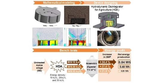
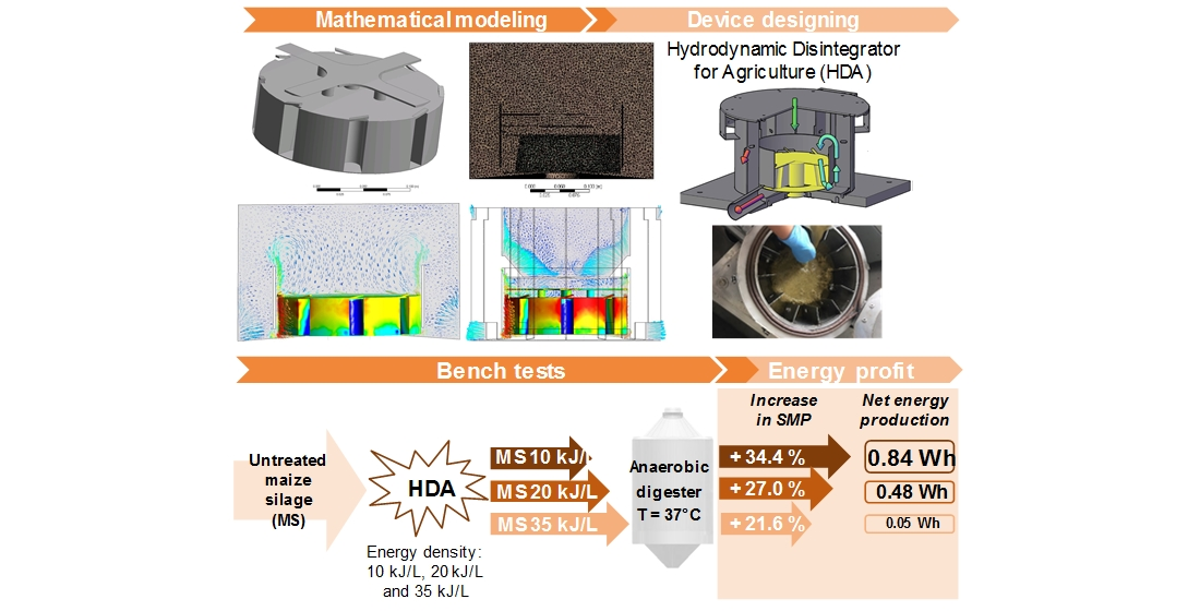
Innovative Hydrodynamic Disintegrator Adjusted to Agricultural Substrates Pre-treatment Aimed at Methane Production Intensification—CFD Modelling and Batch Tests


 , , and
Abstract
:
1. Introduction
2. Methods
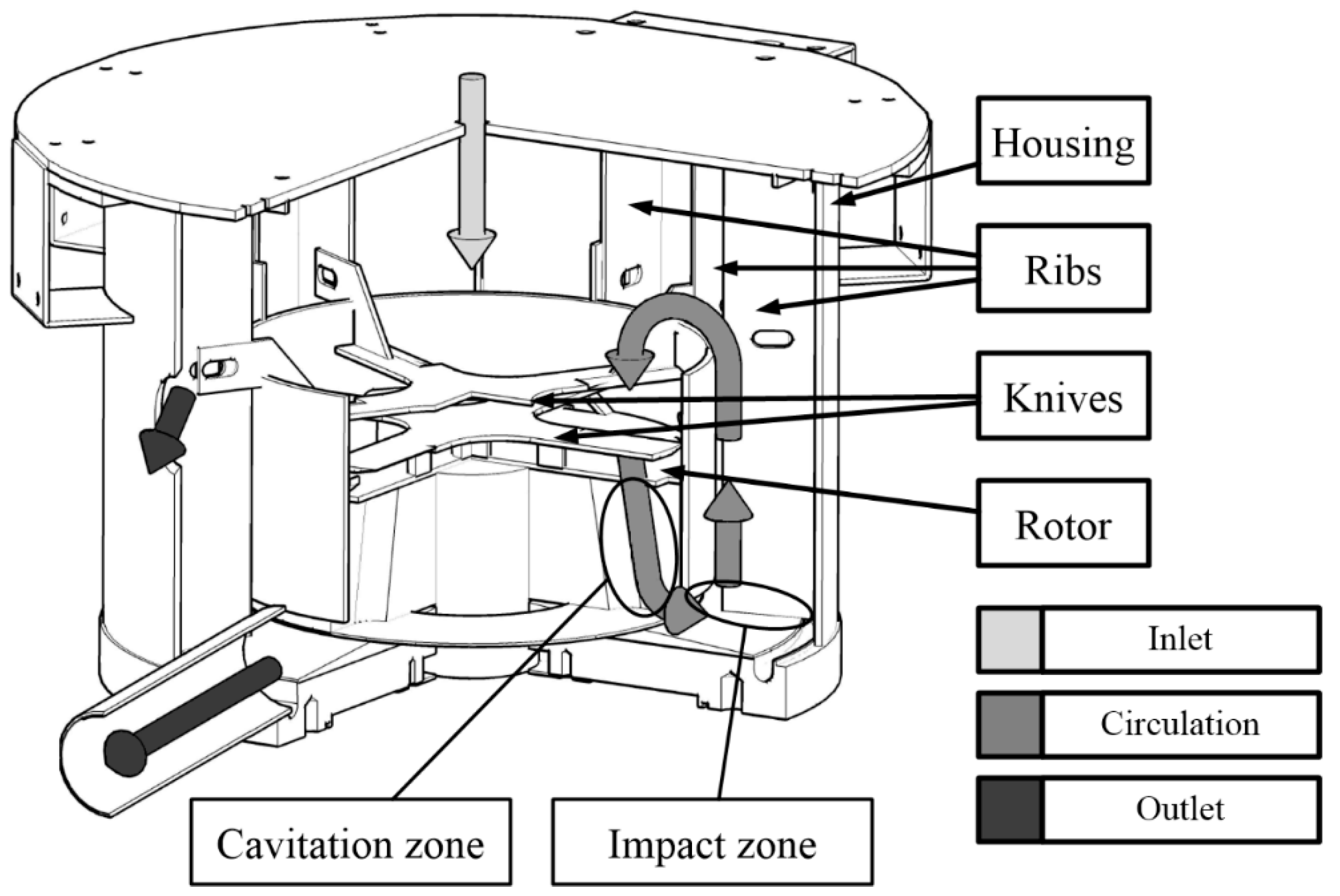
2.1. Modelling
2.1.1. Mathematical Model
2.1.2. Model Implementation
2.2. Appraisal of Device Operation
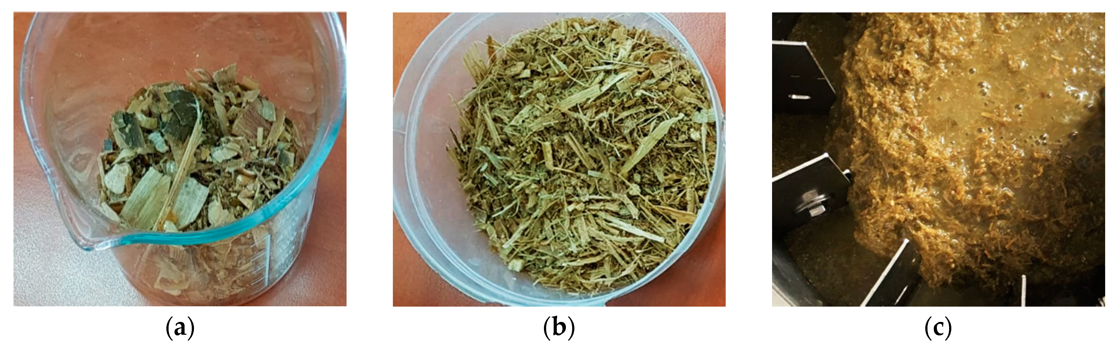
2.2.1. Substrate
2.2.2. Disintegration Batch Test
2.2.3. Biochemical Methane Potential Tests
2.2.4. Analytics
3. Results
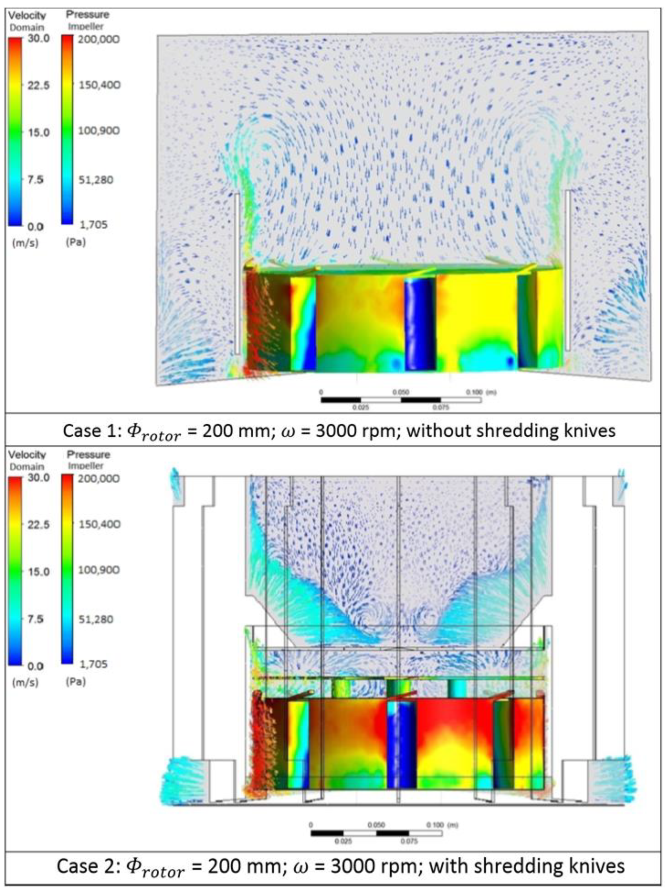
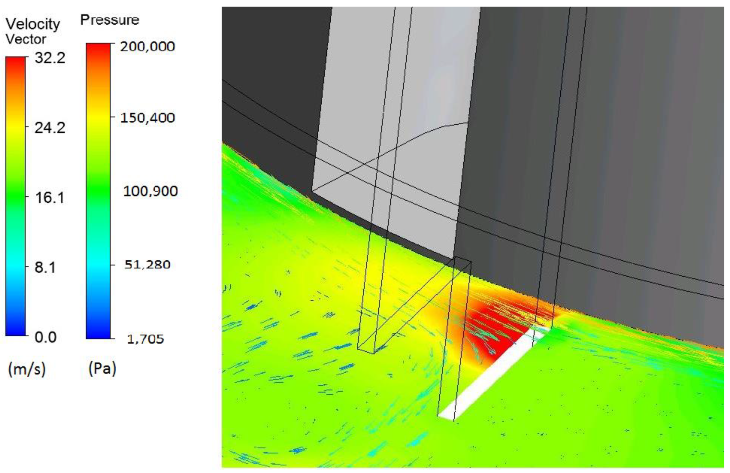
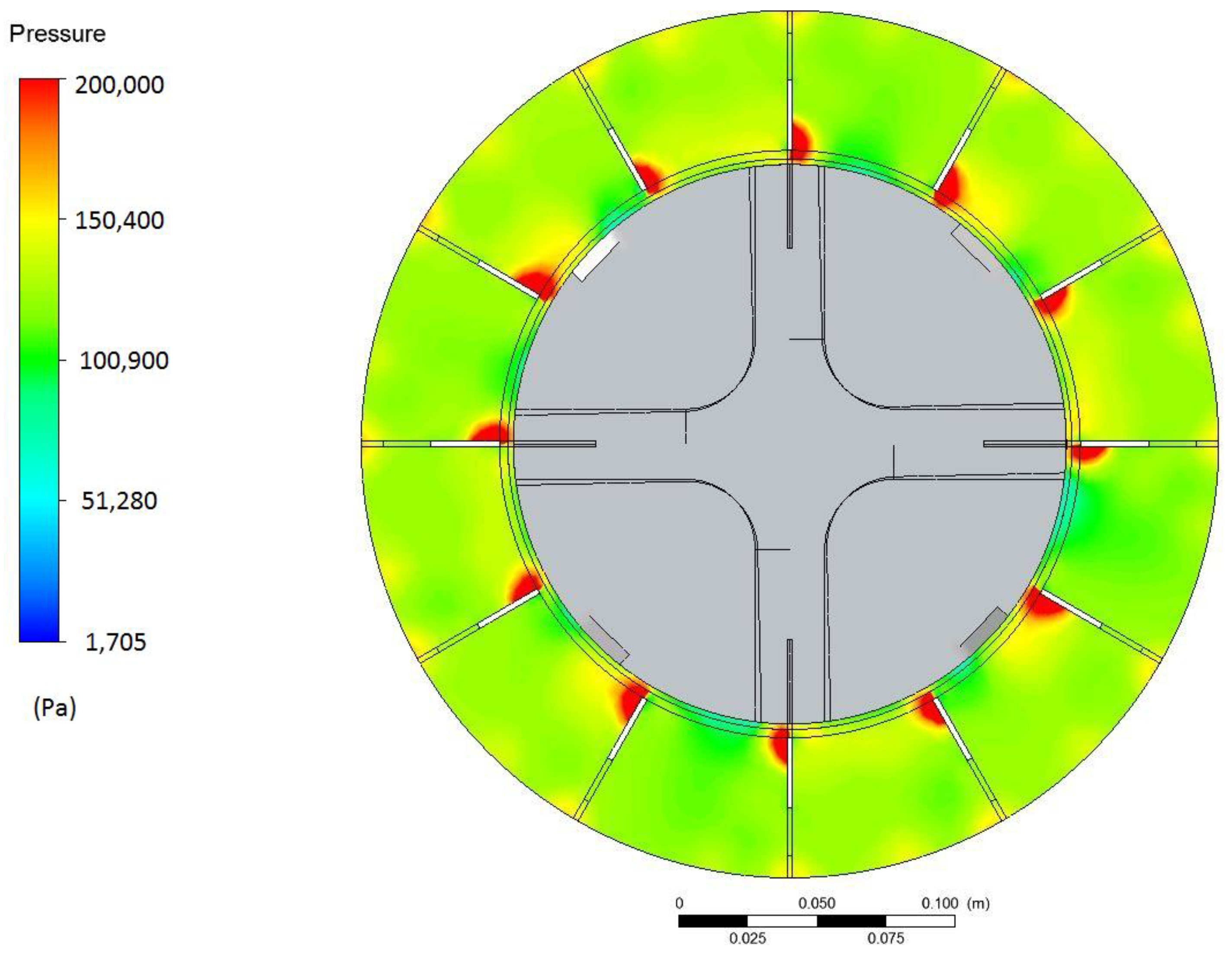
3.1. Modelling
3.2. Appraisal of Device Operation
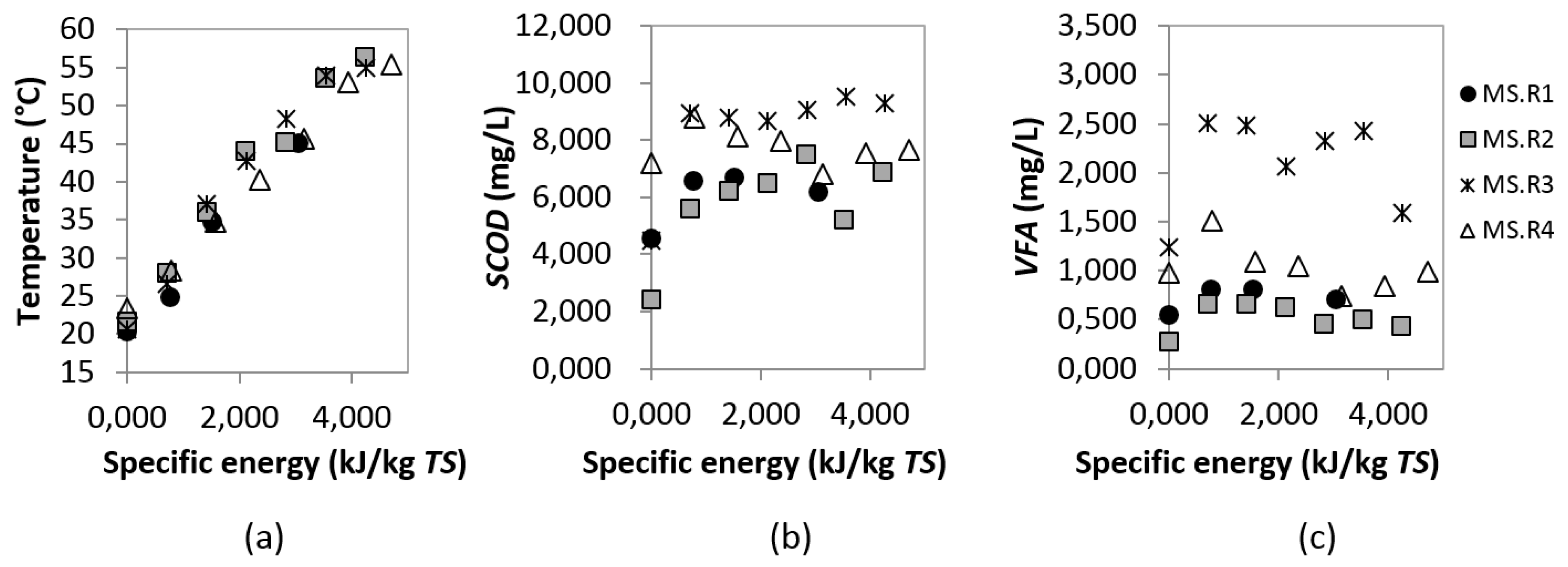
3.2.1. Temperature
3.2.2. SCOD and VFA
3.2.3. Specific Methane Production (SMP)
3.2.4. Energy Balance
4. Conclusions
Author Contributions
Funding
Conflicts of Interest
Abbreviations
| AMPTS II | Automatic Methane Potential Test System |
| BMP | biochemical methane potential |
| CFD | computational fluid dynamics |
| EL | energy density |
| ES | specific energy |
| ESCOD_AW | the efficiency of organic compounds release |
| EVFA_AW | the efficiency of volatile fatty acids release |
| HD | hydrodynamic disintegration |
| HDA | hydrodynamic disintegrator for agriculture |
| HDS | hydrodynamic disintegrator for sludge |
| MS | maize silage |
| R | repetition |
| RANS | Reynolds averaged Navier–Stokes |
| REP | relative energy profit |
| RMS | root mean square |
| SCOD | soluble chemical oxygen demand |
| SBP | specific biogas production |
| SMP | specific methane production |
| SST | shear stress transport |
| TS | total solids |
| VFA | volatile fatty acids |
| VS | volatile solid |
References
- Directive (EU) 2018/2001 of the European Parlament and of the Council on the Promotion of the Use of Energy from Renewable Sources. 2018. Available online: www.eur-lex.europa.eu (accessed on 30 June 2020).
- Schöpe, M. Renewable energy directive. Eur. Wind Energy Conf. Exhib. 2008, 1, 32–38. [Google Scholar]
- Eurostat. Share of Energy from Renewable Sources. 2020. Available online: www.ec.europa.eu (accessed on 30 June 2020).
- Bioenergy Europe. Statistical Report 2019 on Biogas. 2020. Available online: www.bioenergyeurope.org (accessed on 30 June 2020).
- Fernandez, H.C.; Franco, R.T.; Bayard, R.; Buffiere, P. Mechanical Pre-treatments Evaluation of Cattle Manure Before Anaerobic Digestion. Waste Biomass Valoriz. 2020, 1–10. [Google Scholar] [CrossRef]
- Bolado-Rodríguez, S.; Toquero, C.; Martín-Juárez, J.; Travaini, R.; García, P.; Rodríguez, S.B. Effect of thermal, acid, alkaline and alkaline-peroxide pretreatments on the biochemical methane potential and kinetics of the anaerobic digestion of wheat straw and sugarcane bagasse. Bioresour. Technol. 2016, 201, 182–190. [Google Scholar] [CrossRef]
- Li, P.; He, C.; Li, G.; Ding, P.; Lan, M.; Gao, Z.; Jiao, Y. Biological pretreatment of corn straw for enhancing degradation efficiency and biogas production. Bioengineered 2020, 11, 251–260. [Google Scholar] [CrossRef] [Green Version]
- Lee, I.; Han, J.-I. The effects of waste-activated sludge pretreatment using hydrodynamic cavitation for methane production. Ultrason. Sonochem. 2013, 20, 1450–1455. [Google Scholar] [CrossRef]
- Garuti, M.; Langone, M.; Fabbri, C.; Piccinini, S. Monitoring of full-scale hydrodynamic cavitation pretreatment in agricultural biogas plant. Bioresour. Technol. 2018, 247, 599–609. [Google Scholar] [CrossRef]
- Żubrowska-Sudoł, M.; Podedworna, J.; Sytek-Szmeichel, K.; Bisak, A.; Krawczyk, P.; Garlicka, A. The effects of mechanical sludge disintegration to enhance full-scale anaerobic digestion of municipal sludge. Therm. Sci. Eng. Prog. 2018, 5, 289–295. [Google Scholar] [CrossRef]
- Petkovšek, M.; Mlakar, M.; Levstek, M.; Stražar, M.; Širok, B.; Dular, M. A novel rotation generator of hydrodynamic cavitation for waste-activated sludge disintegration. Ultrason. Sonochem. 2015, 26, 408–414. [Google Scholar] [CrossRef]
- Zieliński, M.; Dębowski, M.; Kisielewska, M.; Nowicka, A.; Rokicka, M.; Szwarc, K. Cavitation-based pretreatment strategies to enhance biogas production in a small-scale agricultural biogas plant. Energy Sustain. Dev. 2019, 49, 21–26. [Google Scholar] [CrossRef]
- Zieliński, M.; Rusanowska, P.; Krzywik, A.; Dudek, M.; Nowicka, A.; Dębowski, M. Application of Hydrodynamic Cavitation for Improving Methane Fermentation of Sida hermaphrodita Silage. Energies 2019, 12, 526. [Google Scholar] [CrossRef] [Green Version]
- Hilares, R.T.; Kamoei, D.V.; Ahmed, M.A.; Da Silva, S.S.; Han, J.-I.; Santos, J.C.Z. A new approach for bioethanol production from sugarcane bagasse using hydrodynamic cavitation assisted-pretreatment and column reactors. Ultrason. Sonochem. 2018, 43, 219–226. [Google Scholar] [CrossRef]
- Pal, A.; Verma, A.; Kachhwaha, S.; Maji, S. Biodiesel production through hydrodynamic cavitation and performance testing. Renew. Energy 2010, 35, 619–624. [Google Scholar] [CrossRef]
- Lee, I.; Han, J.-I. Simultaneous treatment (cell disruption and lipid extraction) of wet microalgae using hydrodynamic cavitation for enhancing the lipid yield. Bioresour. Technol. 2015, 186, 246–251. [Google Scholar] [CrossRef]
- Żubrowska-Sudoł, M.; Garlicka, A.; Walczak, J.; Sytek-Szmeichel, K.; Mikołajczak, A.; Stępień, M.; Krawczyk, P.; Umiejewska, K.; Wołowicz, M. Operational characteristics of an innovative device dedicated for the hydrodynamic disintegration of sewage sludge. E3S Web Conf. 2019, 116, 00105. [Google Scholar] [CrossRef]
- Hilares, R.T.; Dionízio, R.M.; Muñoz, S.S.; Prado, C.A.; Júnior, R.D.S.; Da Silva, S.S.; Santos, J.C.Z.; Sanchez, S. Hydrodynamic cavitation-assisted continuous pre-treatment of sugarcane bagasse for ethanol production: Effects of geometric parameters of the cavitation device. Ultrason. Sonochem. 2020, 63, 104931. [Google Scholar] [CrossRef]
- Mancuso, G. Experimental and numerical investigation on performance of a swirling jet reactor. Ultrason. Sonochem. 2018, 49, 241–248. [Google Scholar] [CrossRef]
- Šarc, A.; Perdih, T.S.; Petkovšek, M.; Dular, M. The issue of cavitation number value in studies of water treatment by hydrodynamic cavitation. Ultrason. Sonochem. 2017, 34, 51–59. [Google Scholar] [CrossRef]
- Chanda, S.K. Disintegration of Sludge Using Ozone-Hydrodynamic Cavitation. Master’s Thesis, The University of British Colubia, Vancouver, BC, Canada, 2012. [Google Scholar]
- Kim, H.; Koo, B.; Lee, S.; Yoon, J.Y. Experimental study of cavitation intensity using a novel hydrodynamic cavitation reactor. J. Mech. Sci. Technol. 2019, 33, 4303–4310. [Google Scholar] [CrossRef]
- Tao, Y.; Cai, J.; Huai, X.; Liu, B.; Guo, Z. Application of Hydrodynamic Cavitation to Wastewater Treatment. Chem. Eng. Technol. 2016, 39, 1363–1376. [Google Scholar] [CrossRef]
- Aman, A.; Sileshi, K.; Dribssa, E. Flow simulation and performance prediction of centrifugal pumps using CFD-tool. J. EEA 2011, 28, 59–65. [Google Scholar]
- Bulat, M.P.; Bulat, P.V. Comparison of Turbulence Models in the Calculation of Supersonic Separated Flows. World Appl. Sci. J. 2013, 27, 1263–1266. [Google Scholar]
- Bartosiewicz, Y.; Aidoun, Z.; Desevaux, P.; Mercadier, Y. Numerical and experimental investigations on supersonic ejectors. Int. J. Heat Fluid Flow 2005, 26, 56–70. [Google Scholar] [CrossRef]
- Dzido, A.; Krawczyk, P.; Kurkus-Gruszecka, M. Numerical Analysis of Dry Ice Blasting Convergent-Divergent Supersonic Nozzle. Energies 2019, 12, 4787. [Google Scholar] [CrossRef] [Green Version]
- ANSYS Inc. Innovative Turbulence Modeling: SST Model in ANSYS CFX ®; ANSYS Inc.: Canonsburg, PA, USA, 2004. [Google Scholar]
- Menter, F.R.; Kuntz, M.; Langtry, R. Ten years of industrial experience with the SST turbulence model. Heat Mass Transf. 2003, 4, 625–632. [Google Scholar]
- Bartosiewicz, Y.; Aidoun, Z. CFD-Experiments Integration in the Evaluation of Six Turbulence Models for Supersonic Ejectors Modeling. In Proceedings of the Integrating CFD and Experiments Conference, Glasgow, UK, 8–9 September 2003. [Google Scholar]
- Barrio, R.; Parrondo, J.; Blanco, E. Numerical analysis of the unsteady flow in the near-tongue region in a volute-type centrifugal pump for different operating points. Comput. Fluids 2010, 39, 859–870. [Google Scholar] [CrossRef]
- Yang, S.-S.; Derakhshan, S.; Kong, F.-Y. Theoretical, numerical and experimental prediction of pump as turbine performance. Renew. Energy 2012, 48, 507–513. [Google Scholar] [CrossRef]
- Medvitz, R.B.; Kunz, R.F.; Boger, D.A.; Lindau, J.W.; Yocum, A.M.; Pauley, L.L. Performance Analysis of Cavitating Flow in Centrifugal Pumps Using Multiphase CFD. J. Fluids Eng. 2002, 124, 377–383. [Google Scholar] [CrossRef]
- Wilczyński, L. Stochastic modeling of cavitation phenomena in turbulent flow. Adv. Fluid Mech. 2000, 29, 503–512. [Google Scholar]
- Man, V.H.; Li, M.S.; Derreumaux, P.; Nguyen, P.H. Rayleigh-Plesset equation of the bubble stable cavitation in water: A nonequilibrium all-atom molecular dynamics simulation study. J. Chem. Phys. 2018, 148, 094505. [Google Scholar] [CrossRef]
- Gawin, D.; Sanavia, L.; Schrefler, B.A. Cavitation modelling in saturated geomaterials with application to dynamic strain localization. Int. J. Numer. Methods Fluids 1998, 27, 109–125. [Google Scholar] [CrossRef]
- Linek, T.; Tański, T.; Borek, W. Numerical analysis of the cavitation effect occurring on the surface of steel constructional elements. Arch. Mater. Sci. Eng. 2017, 85, 24–34. [Google Scholar] [CrossRef]
- Shah, S.; Jain, S.V.; Patel, R.N.; Lakhera, V.J. CFD for Centrifugal Pumps: A Review of the State-of-the-Art. Procedia Eng. 2013, 51, 715–720. [Google Scholar] [CrossRef] [Green Version]
- Moloshnyi, O.; Sotnyk, M. Cavitation in centrifugal pump with rotating walls of axial inlet device. IOP Conf. Ser. Mater. Sci. Eng. 2017, 233, 012007. [Google Scholar] [CrossRef] [Green Version]
- Stępień, M.; Krawczyk, P.; Mikołajczak, A.; Wołowicz, M.; Zubrowska-Sudol, M. Analiza pracy cyrkulacyjnego wirnikowego urządzenia do dezintegracji substratów biologicznych przed procesem fermentacji metanowej z zastosowaniem technik CFD. Przemysł Chem. 2019, 1, 100–102. [Google Scholar] [CrossRef]
- Krawczyk, P.; Kurkus-Gruszecka, M.; Mikołajczak, A.; Łapka, P.; Badyda, K. Computational fluid dynamic analysis and valodation of the single stage low pressure rotary lobe compressed air expander. Therm. Sci. 2019, 23, 1–10. [Google Scholar]
- BIP KORW. Available online: http://bip.kowr.gov.pl/informacje-publiczne/odnawialne-zrodla-energii/biogaz-rolniczy/dane-dotyczace-dzialalnosci-wytworcow-biogazu-rolniczego-w-latach-2011-2019 (accessed on 7 June 2020).
- Zubrowska-Sudol, M.; Walczak, J.; Garlicka, A.; Sytek-Szmeichel, K.; Umiejewska, K. How to assess the efficiency of the agro waste disintegration process. Environ. Technol. 2020, 12, 1–11. [Google Scholar] [CrossRef]
- Holliger, C.; Alves, M.M.; Andrade, D.; Angelidaki, I.; Astals, S.; Baier, U.; Bougrier, C.; Buffière, P.; Carballa, M.; De Wilde, V.; et al. Towards a standardization of biomethane potential tests. Water Sci. Technol. 2016, 74, 2515–2522. [Google Scholar] [CrossRef]
- Zubrowska-Sudol, M.; Krawczyk, P.; Garlicka, A.; Sytek-Szmeichel, K.; Walczak, J. Implementation Report of Stage 1: Development of a Technology for Preparation Substrates Used in Methane Co-Fermentation by Disintegration Methods, (DEZMETAN) No.: POIR.04.01.02-00-0022/17. 2020. Available online: https://biopolinex.pl/en/dezmetan-en (accessed on 30 June 2020).
- Zupanc, M.; Kosjek, T.; Petkovšek, M.; Dular, M.; Kompare, B.; Širok, B.; Stražar, M.; Heath, E. Shear-induced hydrodynamic cavitation as a tool for pharmaceutical micropollutants removal from urban wastewater. Ultrason. Sonochem. 2014, 21, 1213–1221. [Google Scholar] [CrossRef] [PubMed]
- Dular, M.; Griessler-Bulc, T.; Gutierrez-Aguirre, I.; Heath, E.; Kosjek, T.; Klemenčič, A.K.; Oder, M.; Petkovšek, M.; Rački, N.; Ravnikar, M.; et al. Use of hydrodynamic cavitation in (waste)water treatment. Ultrason. Sonochem. 2016, 29, 577–588. [Google Scholar] [CrossRef]
- Patil, P.N.; Gogate, P.R.; Csoka, L.; Dregelyi-Kiss, Á.; Horvath, M. Intensification of biogas production using pretreatment based on hydrodynamic cavitation. Ultrason. Sonochem. 2016, 30, 79–86. [Google Scholar] [CrossRef]
- Habashi, N.; Mehrdadi, N.; Mennerich, A.; Alighardashi, A.; Torabian, A. Hydrodynamic cavitation as a novel approach for pretreatment of oily wastewater for anaerobic co-digestion with waste activated sludge. Ultrason. Sonochem. 2016, 31, 362–370. [Google Scholar] [CrossRef] [PubMed]


| Number of Elements | Number of Nodes | Average Quality | Average Aspect Ratio | Average Skewness |
|---|---|---|---|---|
| 1,395,719 | 261,127 | 0.84047 | 1.846 | 0.21973 |
| Energy Density (kJ/L) | Duration of Hydrodynamic Disintegration (min:sec) | Temperature (°C) | SCOD (mg/L) | VFA (mg/L) | ESCOD_AW (mgSCOD/kJ) | EVFA_AW (mgVFA/kJ) |
|---|---|---|---|---|---|---|
| 0 (untreated) | - | 21.5 ±1.4 | 4660 ± 1957 | 760 ± 427 | − | − |
| 35 | 00:41 ± 00:04 | 27.0 ± 1.7 | 7487 ± 1650 | 1377 ± 841 | 80.8 ± 37.0 | 17.6 ± 2.9 |
| 70 | 02:03 ± 00:12 | 35.6 ± 1.1 | 7450 ± 1192 | 1263 ± 832 | 39.9 ± 22.2 | 7.2 ± 7.2 |
| 105 | 04:04 ± 00:26 | 42.4 ± 1.9 | 7700 ± 1113 | 1248 ± 740 | 28.6 ± 18.4 | 4.0 ± 3.7 |
| 140 | 06:48 ± 00:41 | 46.0 ± 1.5 | 7379 ± 1239 | 1059 ± 856 | 19.4 ± 18.4 | 2.1 ± 4.0 |
| 175 | 09:57 ± 02:02 | 53.5 ± 0.5 | 7430 ± 2157 | 1261 ± 1028 | 15.6 ± 13.5 | 2.5 ± 3.9 |
| 210 | 13:07 ± 04:05 | 55.6 ± 0.7 | 7943 ± 1220 | 1001 ± 577 | 15.5 ± 11.5 | 0.8 ± 0.8 |
| Feedstocks | Parameters of the HD Process | Working Volume of the Reactor | Temperature of Anaerobic Digestion Process (°C) | SMP (NmL/gVS) | Increase in SMP Relative to Untreated Sample (%) | References |
|---|---|---|---|---|---|---|
| wheat straw | untreated | 500 mL | 37 | 31.8 | − | Patil et al. [48] |
| (2 min, 7.5 kW, 2300 rpm) | 77.9 | 144 | ||||
| cattle manure and straw wheat | untreated | 20.9 m3 | 35 | 369 1 | − | Zieliński et al. [12] |
| 4 kW, 2800 rpm | 430 1 | 16.5 | ||||
| Sida hermaphrodita silage | untreated | 400 mL | 37 | 340 | − | Zieliński et al. [13] |
| 504 kJ/kg TS | 390 | 14.7 | ||||
| 2988 kJ/kg TS | 440 | 30.0 | ||||
| pig slurry, energy crops (maize silage and triticale silage), and agricultural by-products (beet molasses and corn meal) | untreated | 1.35 L | 38 | 139.4 | − | Garuti et al. [9] |
| 470 kJ/kg TS | 144.1 | 3.50 | ||||
| 740 kJ/kg TS | 159.1 | 14.0 | ||||
| 954 kJ/kg TS | 143.4 | 2.90 | ||||
| maize silage (MS-E1) | untreated | 400 mL | 37 | 302 | − | This study |
| 35 kJ/L (797 kJ/kg TS) | 346 | 14.6 | ||||
| 70 kJ/L (1518 kJ/kgTS) | 312 | 3.31 | ||||
| 140 kJ/L (3125 kJ/kg TS) | 302 | − | ||||
| maize silage (MS-E2) | untreated | 400 mL | 37 | 366 | − | |
| 10 kJ/L (291 kJ/kg TS) | 492 | 34.4 | ||||
| 20 kJ/L (542 kJ/kg TS) | 465 | 27.0 | ||||
| 35 kJ/L (1009 kJ/kg TS) | 445 | 21.6 |
| Parameters | Unit | MS_E1 | MS_E2 | ||||||
|---|---|---|---|---|---|---|---|---|---|
| Untreated MS | MS 35 kJ/L | MS 70 kJ/L | MS 140 kJ/L | Untreated MS | MS 10 kJ/L | MS 20 kJ/L | MS 35 kJ/L | ||
| Methane energy content 1 | (Wh) | 3.13 | 3.46 | 3.12 | 3.02 | 7.32 | 9.84 | 9.30 | 8.90 |
| Electricity 2 | (Wh) | 1.25 | 1.38 | 1.25 | 1.20 | 2.93 | 3.94 | 3.72 | 3.56 |
| Extra electricity 3 | (Wh) | − | 0.13 | 0.00 | 0,00 | − | 1.01 | 0.79 | 0.63 |
| Energy applied for HD | (Wh) | − | 0.23 | 0.42 | 0.91 | − | 0.17 | 0.31 | 0.58 |
| Net energy production | (Wh) | − | −0.10 | −0.42 | −0.91 | − | 0.84 | 0.48 | 0.05 |
| Relative energy profit (REP) | (%) | − | − | − | − | − | 599 | 253 | 108 |
© 2020 by the authors. Licensee MDPI, Basel, Switzerland. This article is an open access article distributed under the terms and conditions of the Creative Commons Attribution (CC BY) license (http://creativecommons.org/licenses/by/4.0/).
Share and Cite
Zubrowska-Sudol, M.; Dzido, A.; Garlicka, A.; Krawczyk, P.; Stępień, M.; Umiejewska, K.; Walczak, J.; Wołowicz, M.; Sytek-Szmeichel, K. Innovative Hydrodynamic Disintegrator Adjusted to Agricultural Substrates Pre-treatment Aimed at Methane Production Intensification—CFD Modelling and Batch Tests. Energies 2020, 13, 4256. https://doi.org/10.3390/en13164256
Zubrowska-Sudol M, Dzido A, Garlicka A, Krawczyk P, Stępień M, Umiejewska K, Walczak J, Wołowicz M, Sytek-Szmeichel K. Innovative Hydrodynamic Disintegrator Adjusted to Agricultural Substrates Pre-treatment Aimed at Methane Production Intensification—CFD Modelling and Batch Tests. Energies. 2020; 13(16):4256. https://doi.org/10.3390/en13164256
Chicago/Turabian StyleZubrowska-Sudol, Monika, Aleksandra Dzido, Agnieszka Garlicka, Piotr Krawczyk, Michał Stępień, Katarzyna Umiejewska, Justyna Walczak, Marcin Wołowicz, and Katarzyna Sytek-Szmeichel. 2020. "Innovative Hydrodynamic Disintegrator Adjusted to Agricultural Substrates Pre-treatment Aimed at Methane Production Intensification—CFD Modelling and Batch Tests" Energies 13, no. 16: 4256. https://doi.org/10.3390/en13164256
APA StyleZubrowska-Sudol, M., Dzido, A., Garlicka, A., Krawczyk, P., Stępień, M., Umiejewska, K., Walczak, J., Wołowicz, M., & Sytek-Szmeichel, K. (2020). Innovative Hydrodynamic Disintegrator Adjusted to Agricultural Substrates Pre-treatment Aimed at Methane Production Intensification—CFD Modelling and Batch Tests. Energies, 13(16), 4256. https://doi.org/10.3390/en13164256