Article

Influence of the Size and Shape of Magnetic Core on Thermal Parameters of the Inductor

Department of Marine Electronics, Gdynia Maritime University, Morska 83, 81-225 Gdynia, Poland
*
Author to whom correspondence should be addressed.
Energies 2020, 13(15), 3842; https://doi.org/10.3390/en13153842
Submission received: 12 June 2020 / Revised: 14 July 2020 / Accepted: 24 July 2020 / Published: 27 July 2020
(This article belongs to the Special Issue Latest Advances in Electrothermal Models)

Abstract

:
In this paper, a new thermal model of the inductor is proposed. This model takes into account self-heating in the core and in the winding, and mutual thermal couplings between the mentioned components of the inductor. The form of the elaborated thermal model is presented. In this model, the influence of power dissipated in the core and in the winding of the inductor on the efficiency of heat removal is taken into account. Correctness of the model is verified experimentally for inductors containing ferrite cores of different shapes and dimensions. The good agreement between the results of calculations and measurements is obtained. On the basis of the obtained findings, the influence of volume and the shape of the core on thermal resistances and thermal capacitances occurring in this model is discussed.

Graphical Abstract

1. Introduction

Inductors are important components of switch-mode power converters. These components are used to store electrical energy [1,2,3,4,5]. Properties of these components indeed depend on physical phenomena occurring in the winding and in the ferromagnetic core contained in the inductor [1,6,7,8,9,10]. At present, producers of ferromagnetic cores offer many types of cores made of different ferromagnetic materials. However, the most frequently used material to construct inductor cores are ferrites produced as a result of dwighting powdered metal oxides. Ferrites are characterised by high hardness, high resistivity, and low losses of eddy currents [5,9,10,11,12,13,14].
When an inductor operates in switched mode power converters an increase in power losses in this component is observed, which is the effect of current flowing through the winding of the inductor and remagnetisation of its core [1,5,6,7,8,9,10,11,12,13,14,15,16]. Power losses in the inductor are converted into heat. Heat generated in components of the inductor causes an increase in temperature of both the core and the winding above ambient temperature as a result of self-heating phenomena and mutual thermal couplings between the core and the winding of the inductor [8,11,15,17,18,19].
Temperature strongly influences the properties of electronic components, especially their reliability [20,21,22]. Therefore, it is essential to know the value of internal temperature of any element in the anticipated conditions of its operation. To calculate this temperature at well-known waveforms of power lost in the element, thermal models are used [23,24,25,26].
Thermal models presented in the literature have a character of microscopic models [6,7,27,28], dedicated to calculate distribution of temperature in the electronic component or macroscopic (compact) models [8,29,30,31], making it possible to calculate one value of internal temperature of the whole electronic component. Microscopic models, due to a high level of complexity, are not frequently used to analyse electronic circuits and they are used only to analyse thermal properties of single electronic components.
Typically compact thermal models are used. These models are often presented in the form of a network analogue [23,24,29,30,32]. Such an analogue usually consists of the current source, representing power dissipated in the modelled component and the RC network representing transient thermal impedance Zth(t), characterising the ability of a component to remove heat generated in this component [23,24,25,26]. Voltage on the current source corresponds to an excess of internal temperature of this component above ambient temperature [23,24,25,26].
The compact thermal model takes into account simultaneously all mechanisms of heat removal to the surroundings, i.e., conduction, convention, and radiation [24,30]. Transient thermal impedance occurring in the compact thermal model is typically described with the use of dependence of the form [24,29,30].
Z t h ( t ) = R t h [ 1 i = 1 N a i exp ( t τ t h i ) ]
where Rth is thermal resistance and N the number of thermal time constants τthi corresponding to coefficients ai. At the steady-state the value of transient thermal impedance is equal to thermal resistance Rth.
In the literature many compact thermal models of inductors and transformers are described [6,8,15,17,33]. However, these models are highly simplified. Some of them [6,8] do not even take into account differences in temperature between the core and the winding. Thermal models of inductors taking into account nonlinearity of phenomena responsible for heat transfer are not known to the authors. Such nonlinearity is observed, among other things, in thermal models of semiconductor devices [30,34,35] or in the results of measurements of thermal properties of transformers shown among others in the papers [36,37]. Nowadays, there are no compact thermal models of inductors, which take into account influence of nonlinearity of thermal phenomena as well as the shape and the size of the core on thermal parameters of inductors.
The aim of this paper is to examine influence of the size and the shape of the ferromagnetic core and power losses on parameters of a thermal model of the inductor. In Section 2, a new nonlinear thermal model of the inductor is discussed. Section 3 describes a manner of estimation of parameters of the new model. The obtained results of calculations and measurements illustrating the usefulness of the proposed model are shown and discussed in Section 4.

2. New Nonlinear Thermal Model of Inductors

A nonlinear thermal model of inductors presented in this section was developed by the authors. It belongs to a group of compact thermal models of electronic components. Let us assume that these electronic components contain more than one heat source. Such models were described in the literature for IGBT (insulated gate bipolar transistor) modules [23] and LED (light emitting diode) modules [38] in which self-heating phenomena and mutual thermal couplings also occur.
The presented nonlinear thermal model of the inductor takes into account the fact that both the core temperature TC and the winding temperature TW depend on the value of ambient temperature Ta and a temperature excess, which is a result of a self-heating phenomenon in each component of the inductor and mutual thermal couplings between these components. The temperature excess of the inductor component caused by a self-heating phenomenon depends on the transient thermal impedance of the core ZthC(t) and transient thermal impedance of the winding ZthW(t). Thermal couplings between the core and the winding are characterised by mutual transient thermal impedance between the core and the winding ZthCW(t). Nonlinearity of phenomena responsible for transporting heat generated in the inductor to the surroundings is also taken into account.
The new nonlinear thermal model of the inductor is dedicated to the SPICE (simulation program with integrated circuits emphasis) program and has the network form shown in Figure 1.
This model consists of four subcircuits. Two of them, visible on the left side of Figure 1, allow for the calculation of the winding temperature Tw and the core temperature TC. According to the rules of formulating a thermal model of electronic devices the Foster network is used [39]. In the mentioned network, current sources which describe the time dependence of power dissipated in the electronic element are used. Current sources IW and IC correspond to powers dissipated in the winding and in the core. Self-transient thermal impedances of the winding ZthW(t) and the core ZthC(t) are modelled using CWi and CCi capacitors and controlled current sources GWi and GCi. Voltages on these circuits correspond to a temperature excess caused by a self-heating phenomenon occurring in the winding and in the core. Influence of mutual thermal couplings between the core and the winding is modelled using the controlled voltage sources E1 and E2. Voltages on these sources correspond to the values of temperature excesses TWC and TCW. In contrast, voltage sources V1 and V2 model ambient temperature.
The other two subcircuits allow calculating excesses of the core temperature TCW and the winding temperature TWC caused by thermal coupling between the inductor components. In these subcircuits, current sources represent power dissipated in the winding IWC and in the core ICW. The networks connected to these sources model mutual transient thermal impedance between the core and the winding ZthCW(t). All transient thermal impedances occurring in the presented model are described by Equation (1).
As shown in the papers [23,35,36,40], waveforms of transient thermal impedance of electronic components depend on power or internal temperature of the considered electronic component. From the papers [23,36,38] and from measurements performed by the authors, it results that influence of power dissipated in the modelled component practically does not influence heat capacitances of this component, while influence of power dissipated in the considered component on thermal resistance could be significant. Therefore, in the presented nonlinear thermal model of the inductor, constant values of thermal capacitances are used. In contrast, thermal resistances occurring in the considered model depend on power generated in the inductor. Empirical dependence of thermal resistance Rth on the dissipated power p is proposed. This dependence is expressed by the empirical Equation:
R t h = R t h 0 + R t h 1 e x p ( p b )
where is power dissipated in a heating component (core or winding), Rth0, Rth1 and b are the model parameters. Of course, for each of the three transient thermal impedances (1), there is a different set of parameter values describing thermal capacitances and thermal resistances.
Changes of individual components of thermal resistance are modelled using the controlled current sources Gi according to the Equation [33]:
G i = V G i a i R t h
where VGi is voltage on source Gi, Rth thermal resistance calculated using the Equation (2), and ai is the coefficient in the Equation (1) which corresponds to i-th thermal time constants τthi.
Values of parameters occurring in Equations (1) and (2) were determined using the concept of local estimation [41,42] based on the measured waveforms of transient thermal impedances occurring in the considered thermal model of the inductor.

3. Method of Model Parameters Estimation

Values of parameters of the thermal model described in Section 2 can be determined as a result of realisation of a series of measurements and calculations. These measurements are performed in the measuring set-up shown in Figure 2.
The considered set-up contains a voltage source E, a resistor R limiting the value of current, an ammeter, a voltmeter, the examined inductor L, a pyrometer, the acquisition data system DAQ, and a PC. To measure the value of DC current and DC voltage multimeters of the type UNIT UT-803 were used. The uncertainty of the measurements of DC voltage is ±0.025%, of the DC current ±0.1%, and of temperature measured by the pyrometer PT-3S is equal to ±3% [43].
In this set-up transient thermal impedances of the core ZthC(t) and the winding ZthW(t), and also mutual transient thermal impedance between the core and the winding ZthCW(t) are measured. These measurements are realised with the use of the indirect method and the following definitional Equations.
Z t h C ( t ) = T C ( t ) T a p C
Z t h W ( t ) = T W ( t ) T a p W
Z t h W C ( t ) = T C ( t ) T a p W
where pC denotes power dissipated in the inductor core, whereas pW refers to power dissipated in the winding. In Equations (4)–(6), the temperatures of the core and the winding and powers dissipated in the core and in the winding also appear.
In the considered measuring set-up power in the shape of a jump is dissipated during the flow of current through one of two components of the inductor depending on the position of switch S. In the position 1 of the switch, power is dissipated in the core, and in the position 2 of this switch power is dissipated in the winding. The value of current flowing through components of the inductor is regulated by means of voltage source E and resistor R. The temperature of the core is registered by means of the pyrometer PT-3S [43] configured to work in the continuous operation, as well as the card of data acquisition and a computer. In turn, temperature of the winding is measured indirectly on the basis of measurements of the winding resistance.
The value of voltage and current flowing through the core or the winding is regulated over a wide range of the measured waveforms ZthC(t), ZthW(t) and ZthCW(t) for different values of power pC and pW. Basing on the registered waveforms of the mentioned transient thermal impedances of the inductor, values of parameters Rth, ai, τthi occurring in the Equation (1) for every applied value of power pW and pC are estimated using the program ESTYM [42]. For every transient thermal impedance of the modelled inductor at the highest applied values of the dissipated power, average values of parameters ai and thermal capacitances occurring in the proposed thermal model are calculated on the basis of the Equation:
C i = τ t h i a i · R t h
Based on the measured dependences of thermal resistance on power RthC(pC), RthW(pW), and RthCW(pW), values of parameters Rth0, Rth1, and b occurring in Equation (2) are estimated with the method of local estimation [39,40] for every considered dependence separately.

4. Results

In order to analyse influence of the dimensions and the shape of the core on parameters of a non-linear thermal model of the inductor, investigations of the considered component operating in the set-up presented in Figure 2 were performed. Measurements were carried out for inductors with ferrite cores of different shapes and dimensions.
In subsection A the tested inductors are described, in subsection B presents the estimated values of model parameters, and in subsection C, the obtained results of calculations and measurements are presented. On the basis of the obtained results dependences of influence of the mentioned factors on the value of parameters of the presented nonlinear thermal model of the inductor are discussed.

4.1. Tested Inductors

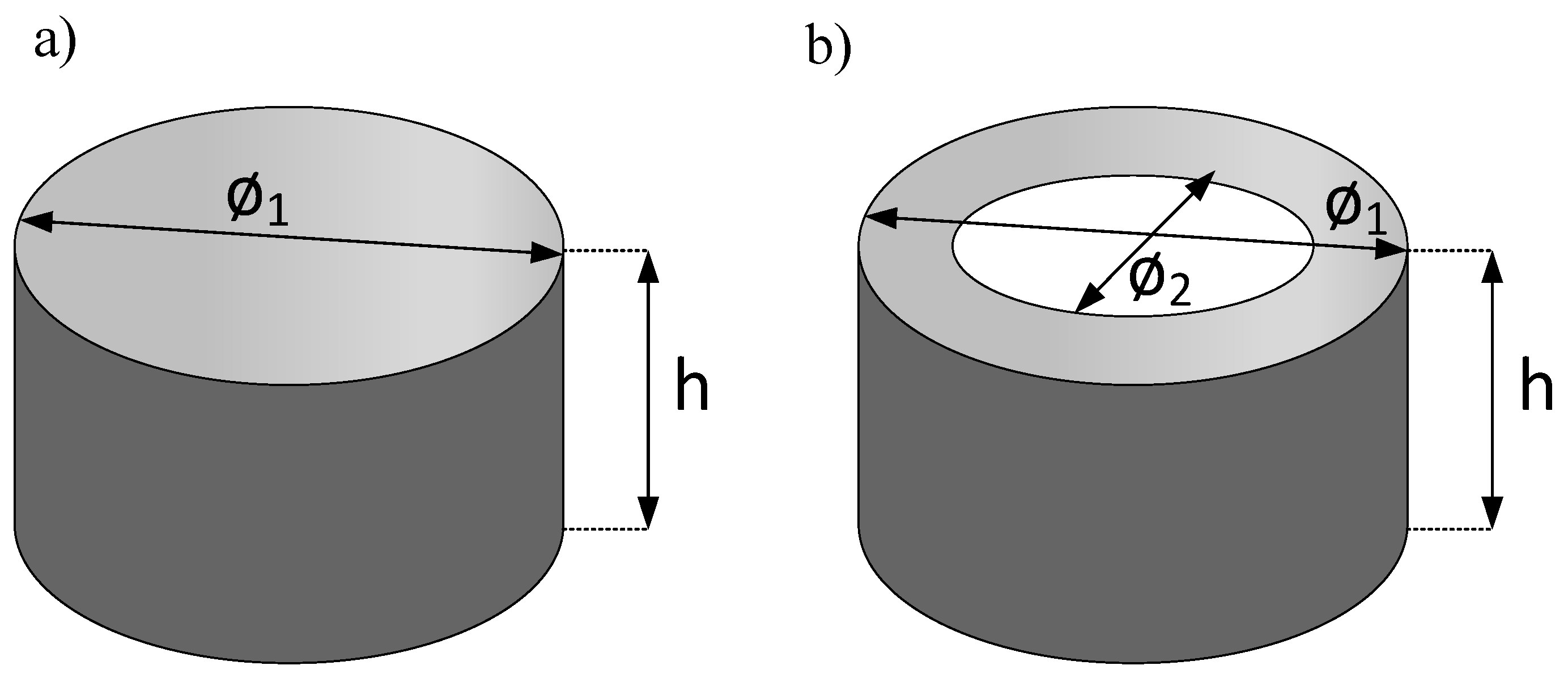
Inductors containing cup and toroidal cores made of ferrite material F-867 [44] were used for investigations. On each core, eight turns of copper wire in the enamel of the diameter 1 mm were wound. The examined inductors with cup cores of different dimensions were mounted on the printed circuit board, which was situated vertically during measurements. The inductor with the ring core was also arranged vertically. In Figure 3, the dimensions of the examined inductor cores are shown.
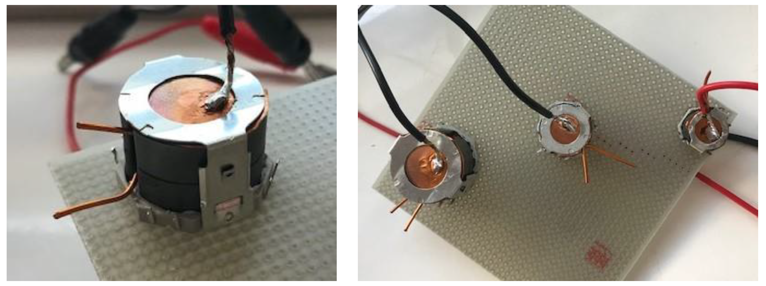
In 
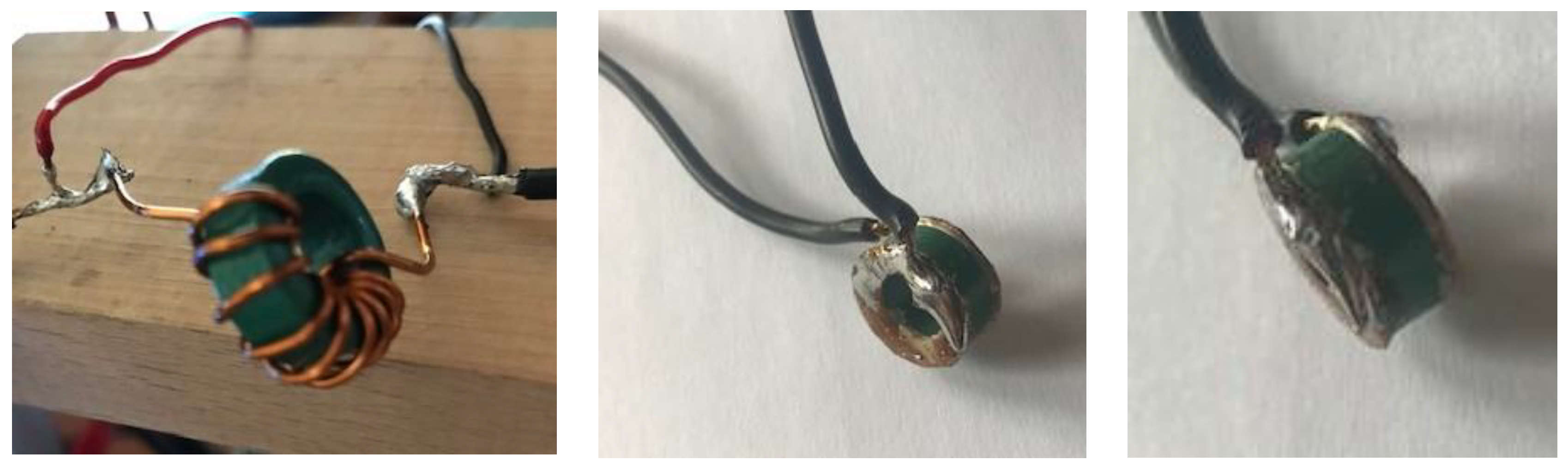
Figure 4, the examined inductors with cup cores installed on the printed circuit board are shown, and in Figure 5 the examined inductor with the ring core is presented. During measurements ambient temperature was monitored and its value fluctuated between 21.9 °C and 23 °C. In both the figures, cables mounted to the ferromagnetic core are visible. These cables are indispensable to enable the current flow through the ferromagnetic core while heating this core. In Table 1 values of selected parameters of material F867 are collected, whereas in Table 2, values of geometrical parameters of the considered inductor cores are given. The inductors with the core whose parameters are collected in Table 2 are shown in Figure 4 and Figure 5.
As shown in Table 1, saturation flux density Bsat decreases with a temperature increase from 0.6 T to 0.4 T, remanence flux density BR does not exceed 0.15 T, coercion force HC amounts to 40 A/m, initial permeability μi strongly depend on temperature and increases from 2400 to 3900. Power losses per unit of volume PV decrease from 129 mW/cm3 to 70 mW/cm3 in the considered changes of temperature. In further part of this paper the considered cup cores will be denoted as: small cup core, medium cup core and big cup core, respectively. In turn, toroidal cores will be denoted as: toroidal core 16, toroidal core 20, toroidal core 30 and toroidal core 40, respectively.
Table 2 shows that the used cores are characterised by different values of such geometrical parameters as: magnetic path length le, cross-section area Ae and volume Ve. For example toroidal core 16 has similar value of le parameter to big cup core le parameter and similar value of Ae parameter to small cup core Ae parameter. Further, the toroidal core 20 has similar value of le parameter to big cup core.

4.2. Parameters Values of a New Model

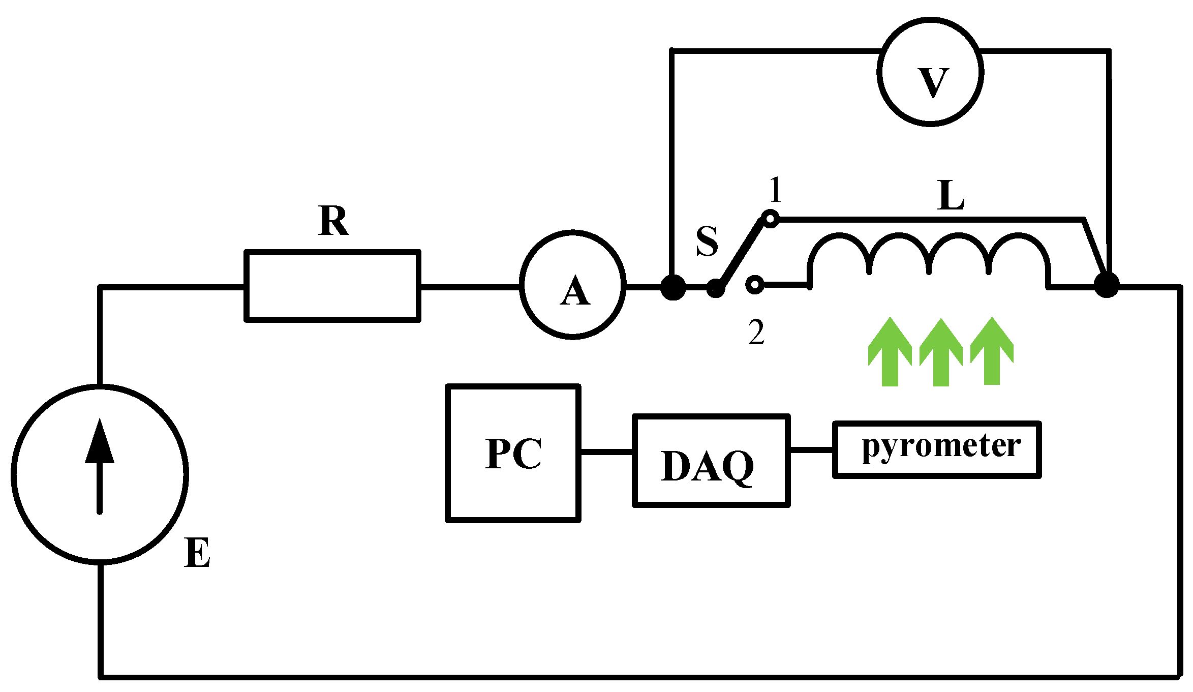
Using the measurement set-up (Figure 2), measurements of transient thermal impedances were performed. They were carried out for all the considered inductors at different values of power dissipated in the cores and windings. Based on the obtained measurement results, values of parameters of the nonlinear thermal model were determined for each considered inductor with the use of the method described in Section 2. For example, values of parameters of this model for inductors with the medium cup core and with the toroidal core of the external diameter equal to 16 mm are presented in Table 3.
As can be observed, for both the inductors, the same number of thermal time constants, related to the coefficients ai, which describe particular transient thermal impedances, is obtained. Values of thermal capacitances characterising thermal properties of the core are higher than those capacitances characterising the winding properties. Values of parameters Rth0 appearing in the description of individual transient thermal impedances are similar for both the considered inductors. In contrast, even ten-fold differences are observed between values of b parameter describing the considered transient thermal impedances.
Table 4 compares the values of parameters of transient thermal impedance of the core ZthC(t) obtained for the inductor with cup cores of different sizes.
As it is visible, an increase in the dimensions of the cup core causes a decrease in the value of parameters Rth0 and Rth1, whereas parameter b achieves maximum value for medium cup core. Also an increase in thermal capacitances values with core size is observed.
Table 5 compares values of parameters of transient thermal impedance of the winding ZthW(t) obtained for the inductor with cup cores of different sizes.
As can be seen, an increase in the dimensions of the cup core causes a decrease in the value of parameters Rth0 and Rth1, whereas parameter b have the same value for both considered cup cores. Additionally, increase in dimensions of the cup core causes a visible increase in the value of thermal capacitance.
Table 6 collects the values of parameters of transient thermal impedance of the core ZthC(t) obtained for the inductor with toroidal cores of different dimensions.
As shown, an increase in the dimensions of the toroidal core causes an increase in the value of parameters Rth0 and thermal capacitances.
Table 7 collects values of parameters of transient thermal impedance of the winding ZthW(t) obtained for the inductor with toroidal core of different dimensions.
As can be observed, an increase in the toroidal core dimensions causes an increase in thermal capacitance and a decrease in the parameter Rth0. For example, parameter Rth0 decreases even triple when the diameter of the core increases 2.5 times.

4.3. Results of Measurements and Calculations

In order to verify the usefulness of the thermal model of inductors proposed in Section 2, some measurements and computation were performed. In computations the nonlinear thermal model of the inductor was used. Results of these measurements and computations are shown in Figure 5, Figure 6, Figure 7, Figure 8, Figure 9, Figure 10, Figure 11, Figure 12, Figure 13, Figure 14, Figure 15, Figure 16 and Figure 17.
In these figures, the results obtained for particular inductors were marked using the following markers and colour rules: an inductor with 14 × 8 mm dimensions of the cup core is marked as the small cup core (blue), an inductor with 18 × 11 mm dimensions of the cup core, the medium cup core (green), and an inductor with 26 × 16 mm dimensions of the cup core is marked as the big cup core (red). An inductor containing toroidal core with 16 mm diameter of the core is marked as a toroidal core 16 (violet), an inductor with 20 mm diameter of the core is marked toroidal core 20 (green), an inductor with 30 mm diameter of the core is marked toroidal core 30 (yellow) and an inductor with 40 mm diameter of the core is marked toroidal core 40 (blue). Additionally, it is worth remembering that the volume of toroidal core with 16 mm diameter corresponding to the volume of medium cup core. In all the figures, lines denote the results of calculations, whereas points refer to the results of measurements.
At first, measured and calculated waveforms of transient thermal impedances occurring in the proposed thermal model of an inductor are presented. Next, dependences illustrating an influence of dissipated power in components of the tested inductors on thermal resistances occurring in the considered model are shown and discussed. Finally, an analytical description of the dependences of thermal resistances and capacitances on the effective volume of the core contained in the tested inductors are proposed and experimentally verified for these inductors.
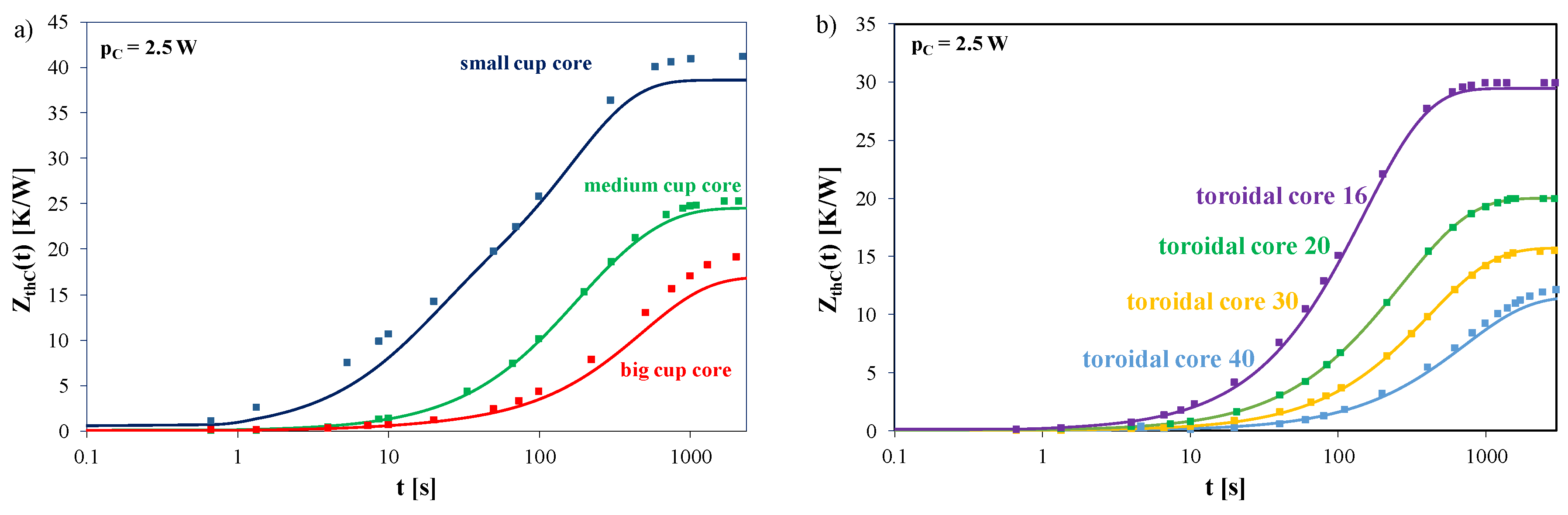
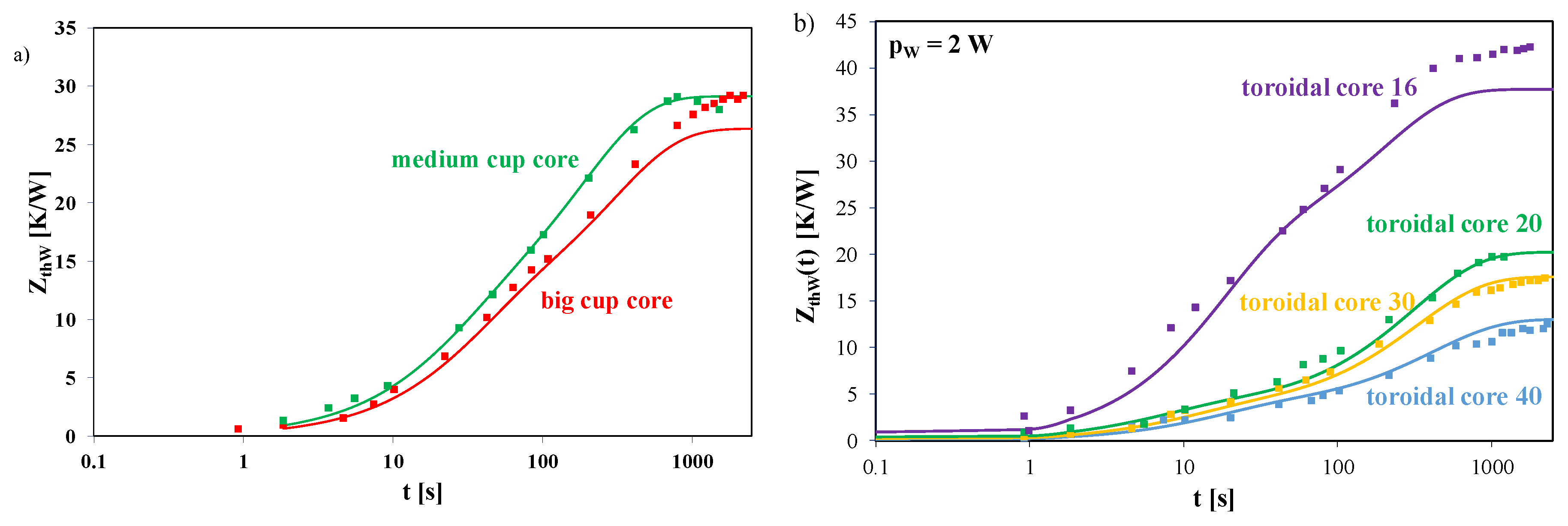
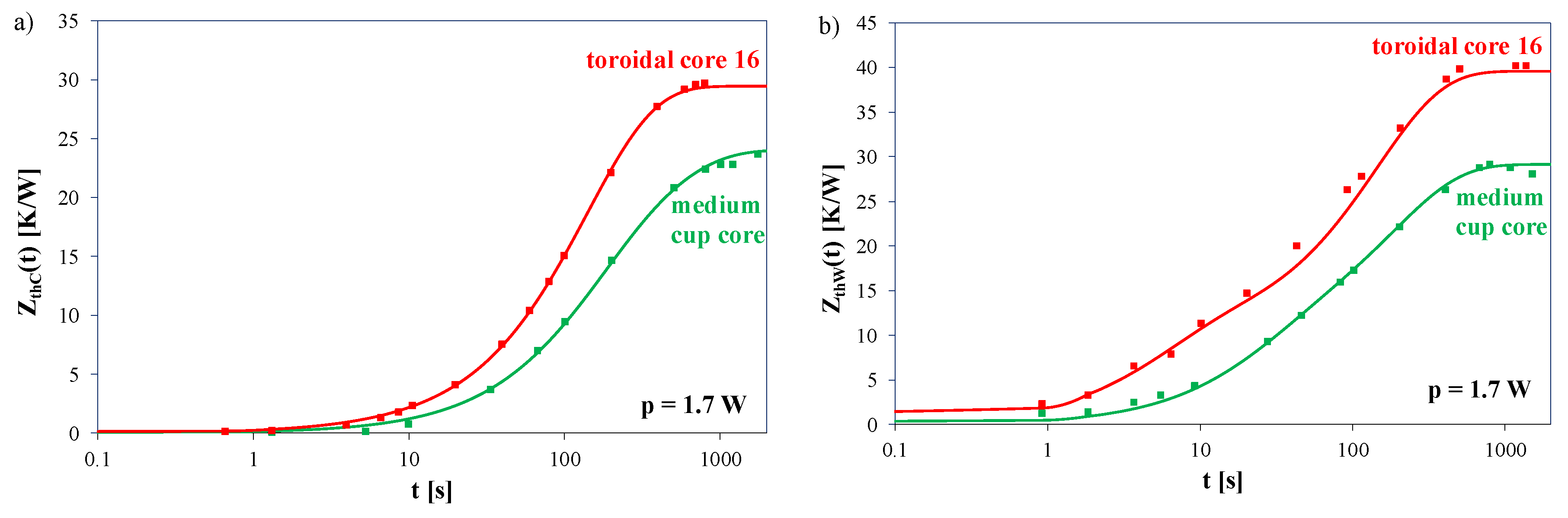
Figure 6 presents the calculated and measured waveforms of transient thermal impedance of the core of the considered inductors containing cup cores (Figure 6a) and toroidal core (Figure 6b) obtained at dissipation in the core the power of the amplitude equal to 2.5 W.
As can be seen, from the obtained waveforms of transient thermal impedance of the core, for the smallest volume of the core, the value of ZthC(t) at the steady state is more than twice higher than the value of ZthC(t) at the steady state for the biggest volume of the core (big cup core) and over 60% higher than the value ZthC(t) at the steady state for the core of medium volume—the medium cup core. It can be concluded from this relation that the ability to remove heat characterised by thermal resistance of the core RthC decreases with an increase in the core size. This is due to an increase in the surface area, at which convection heat transfer rate can occur. On the other hand, the time needed to reach the thermally steady state for the big core of the inductor is more than twice longer for the small inductor core. This means that thermal capacitance of the core increases with its size. In the case of the inductor with the toroidal core with the 16 mm diameter the value of ZthC(t) at the steady state is more than twice higher than the value of ZthC(t) at the steady state for the toroidal core with the 40 mm diameter and about 50% higher than the value of ZthC(t) at the steady state for the toroidal core with the 20 mm diameter. It is also worth noticing that the good agreement between the results of measurements and the results of calculations was obtained. For the toroidal core, the maximum error of calculations does not exceed 5% and for the cup core it is smaller than 8%.
Figure 7 presents the calculated and measured waveforms of transient thermal impedance of the winding of the considered inductors containing cup cores (Figure 7a) and toroidal cores (Figure 7b) obtained at power dissipated in the core equal to 2 W.
As can be seen, from the obtained waveforms of transient thermal impedance of the winding of the inductor with cup cores (Figure 7a), for the medium volume of the core, the value of ZthW(t) at the steady state is the same as the value of ZthW(t) at the steady state for the big cup core. In the case of the inductor with the toroidal core with the 16 mm diameter the value of ZthW(t) at the steady state for the considered inductor is five times higher than for the same inductor with the core with the 40 mm diameter. Additionally, differences between the results of calculations and measurements do not exceed 11% for the inductor with the cup core and 13% for the inductor with the toroidal core.
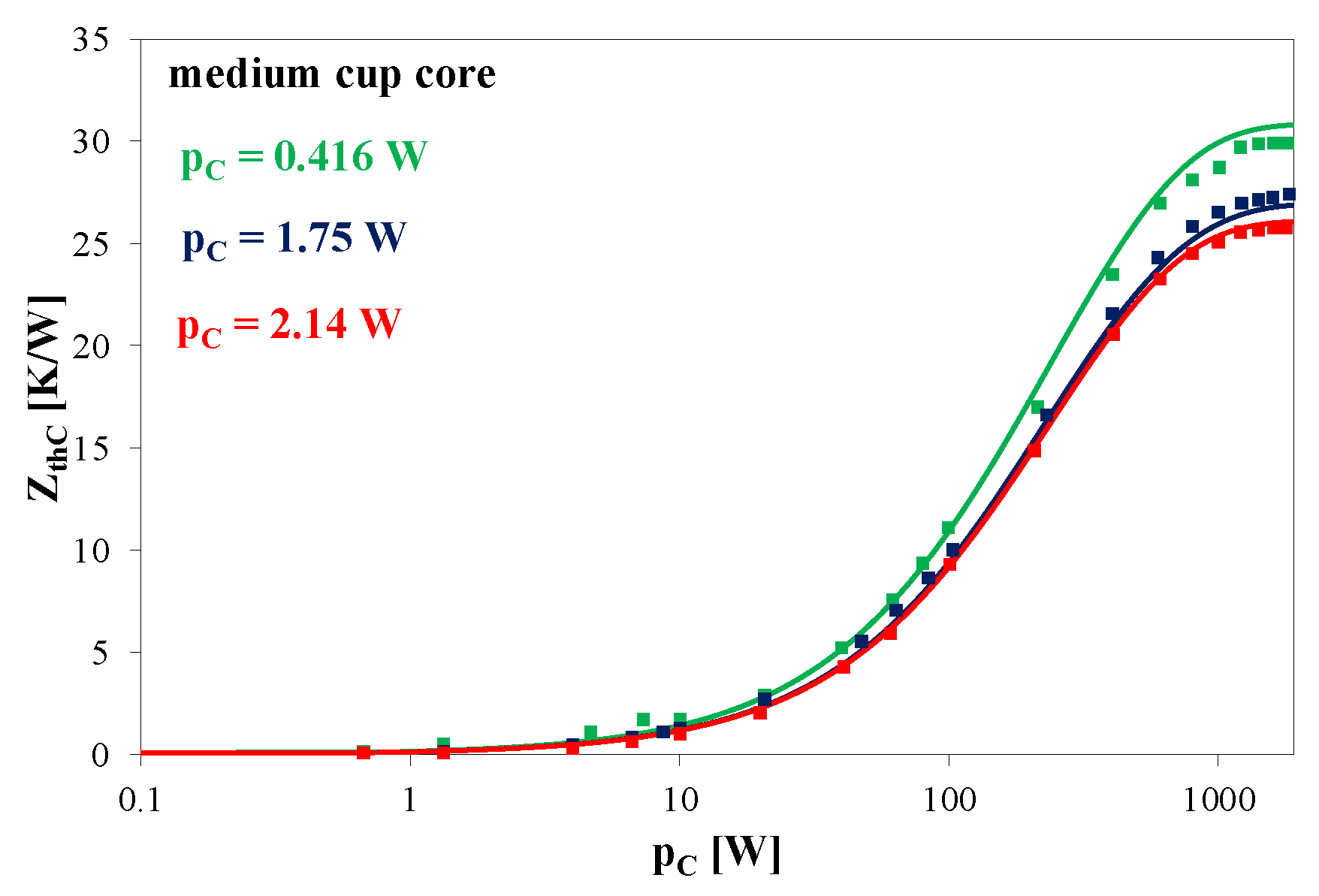
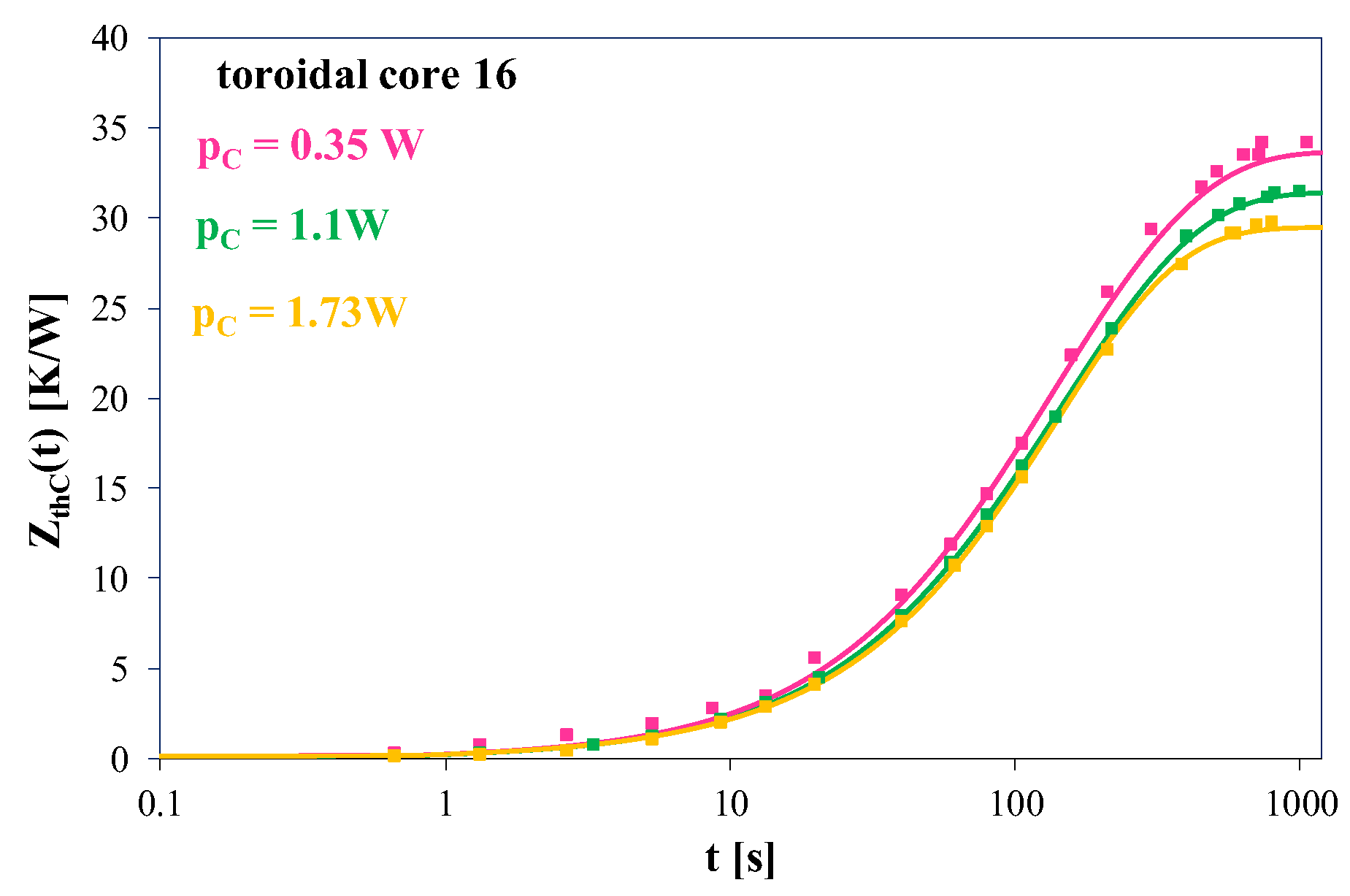
Figure 8 and Figure 9 show the waveforms of thermal transient impedance of the medium cup core (Figure 8) and of the toroidal core (Figure 9) for selected values of power dissipated in the core.
As can be seen in Figure 8, due to changes in power dissipated in the cup core, values of ZthC(t) at the steady state change by not more than 20%. An increase in the value of power causes a decrease of ZthC(t) value. It is observed that power does not influence time indispensable to achieve the steady state of ZthC(t) waveform. This means that thermal capacitance is practically independent of power dissipated in the core.
However, an increase in the value of power dissipated in the toroidal core (Figure 9) causes a decrease in the value of ZthC(t) at the steady state. These changes reach almost 15%. At the same time, it can be seen that the value of power dissipated in the core practically does not influence time, in which the waveform of ZthC(t) achieves the steady state. As can be seen, differences between the results of calculations and measurements do not exceed 3%.
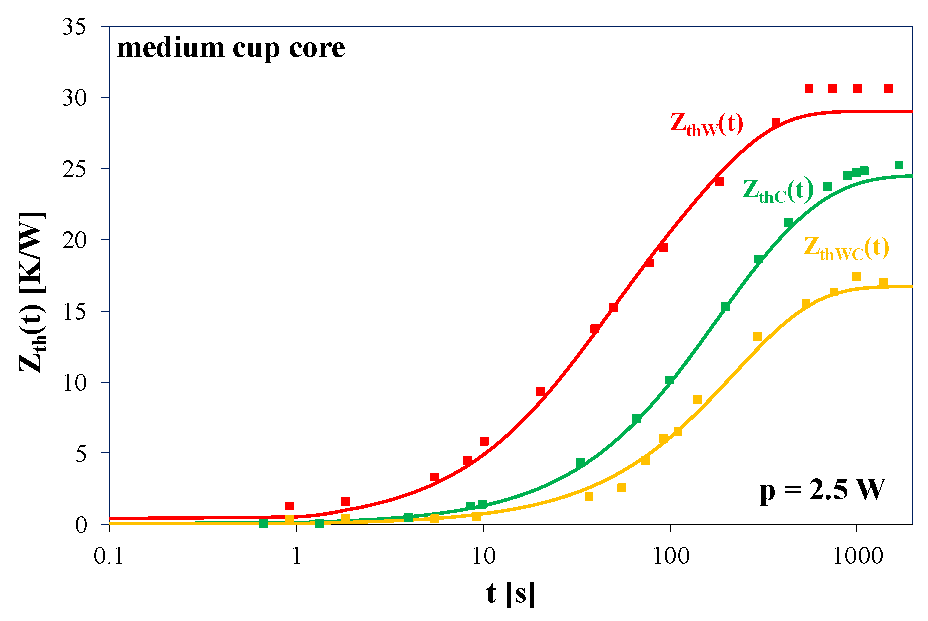
Figure 10 and Figure 11 present the measured and calculated waveforms of transient thermal impedances ZthW(t), ZthC(t), and ZthCW(t) for the inductor containing the medium cup core (
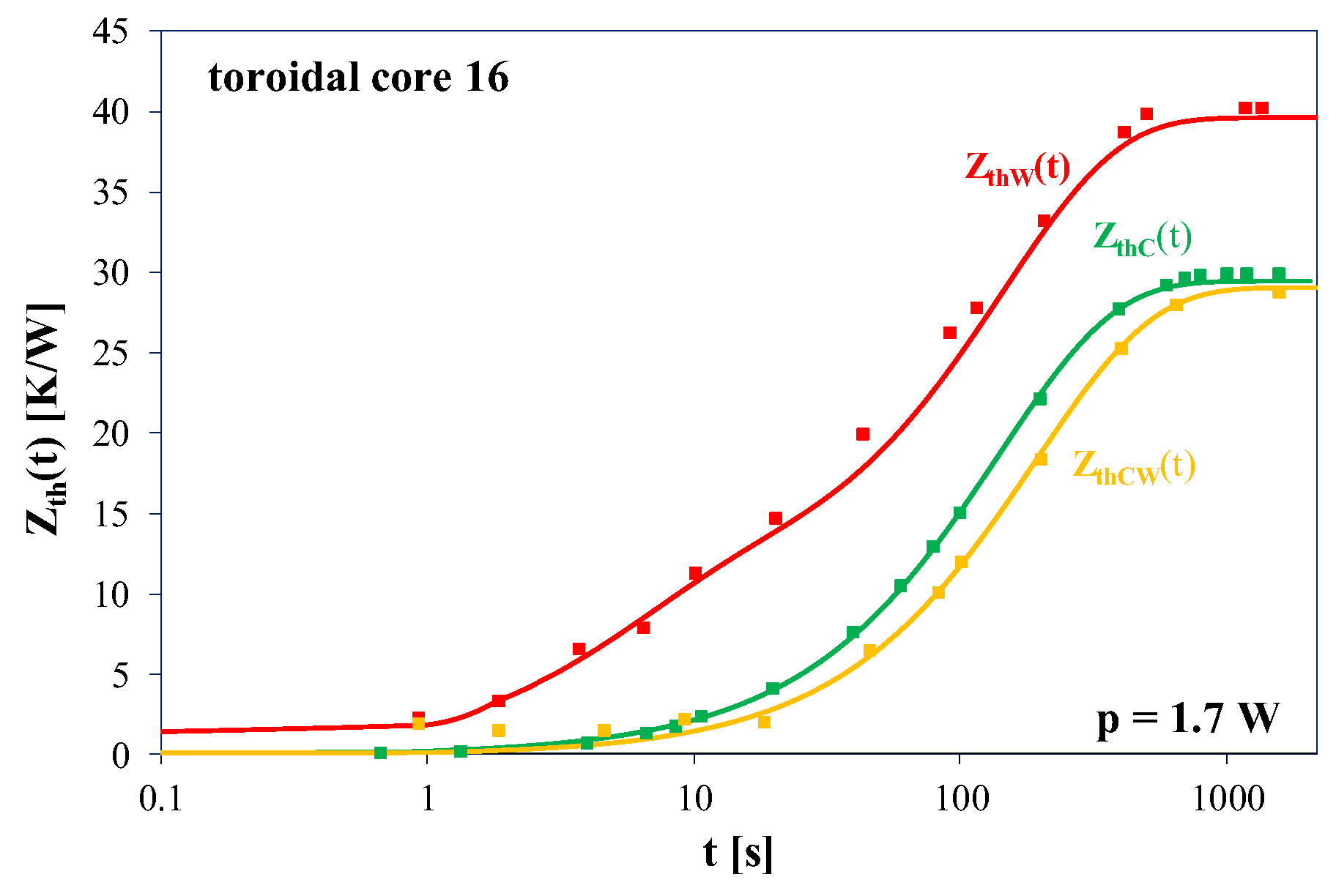
Figure 10) at power dissipated in the core and in the winding equal to 2.5 W, and for the toroidal core, 16 (Figure 11) at power dissipated in the core pC = 1.7 W.
It can be seen that, at the steady state, values of ZthW(t) are up to 50% higher than ZthC(t). Time necessary to obtain the steady state is the shortest for waveform ZthW(t) and the longest for ZthC(t). Differences in the values of these times reach 20%, and are a result, among others, of differences in the mass of the core and windings. Also, the good agreement between the results of measurements and calculations was obtained. The maximum deviation does not exceed 8%.
Similarly to the cup core, the highest values are obtained for ZthW(t) (Figure 11). They are even 30% higher than the value of ZthC(t). Waveforms of ZthC(t) and ZthCW(t) differ from each other by not more than 5%. These differences are due to construction of the inductor, which causes that the winding is directly cooled by the air surrounding the inductor, and due also to the fact that the core is surrounded by the winding, in contrast to the cup core, which is not. Also the good agreement between the results of measurements and calculations is achieved and the differences between them do not exceed 3%.
Figure 12 presents a comparison of waveforms of transient thermal impedances of the core ZthC(t) and the winding ZthW(t) for the inductor containing the toroidal core and the cup core at power dissipated equal to 1.7 W.
The presented comparison shows that values of transient thermal impedances ZthC(t) and ZthW(t) are about 30% higher for the inductor with the toroidal core. The setting time for ZthC(t) waveform is longer for the inductor with the cup core, while the setting time for ZthW(t) waveform is practically the same. In this case, the error of calculations does not exceed 3%.
Figure 13, Figure 14 and 
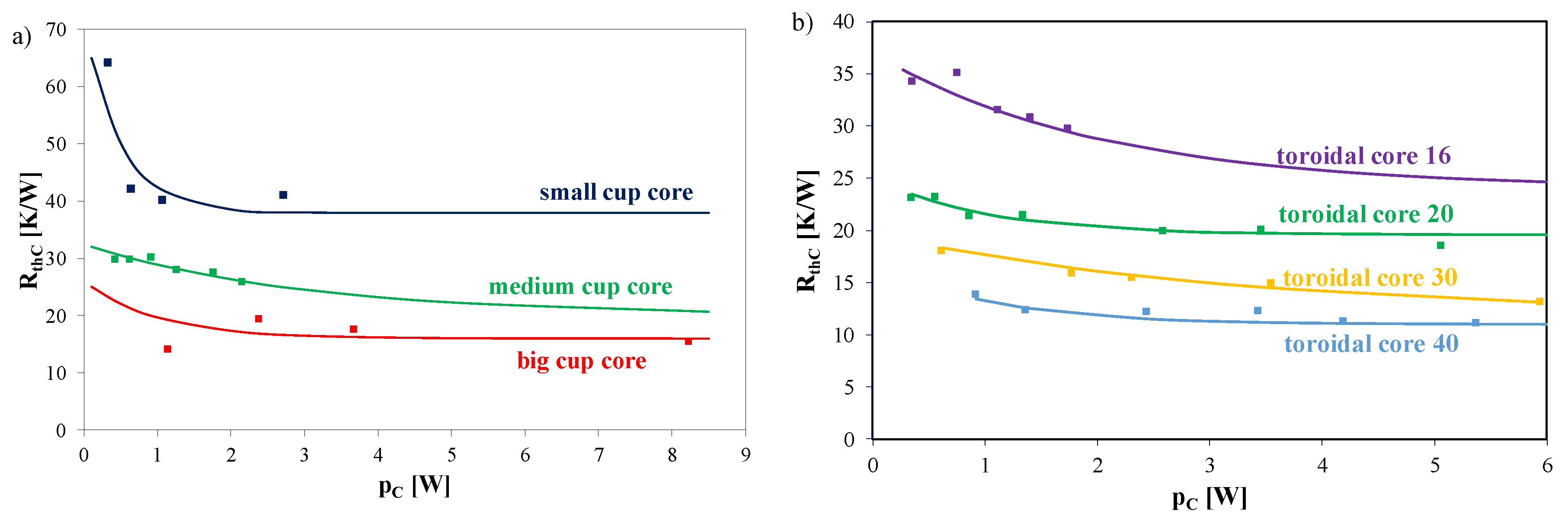
Figure 15 shows the calculated with the use of the Equation (2) and measured dependences of thermal resistances RthC (Figure 13), RthW (Figure 14), RthWC (
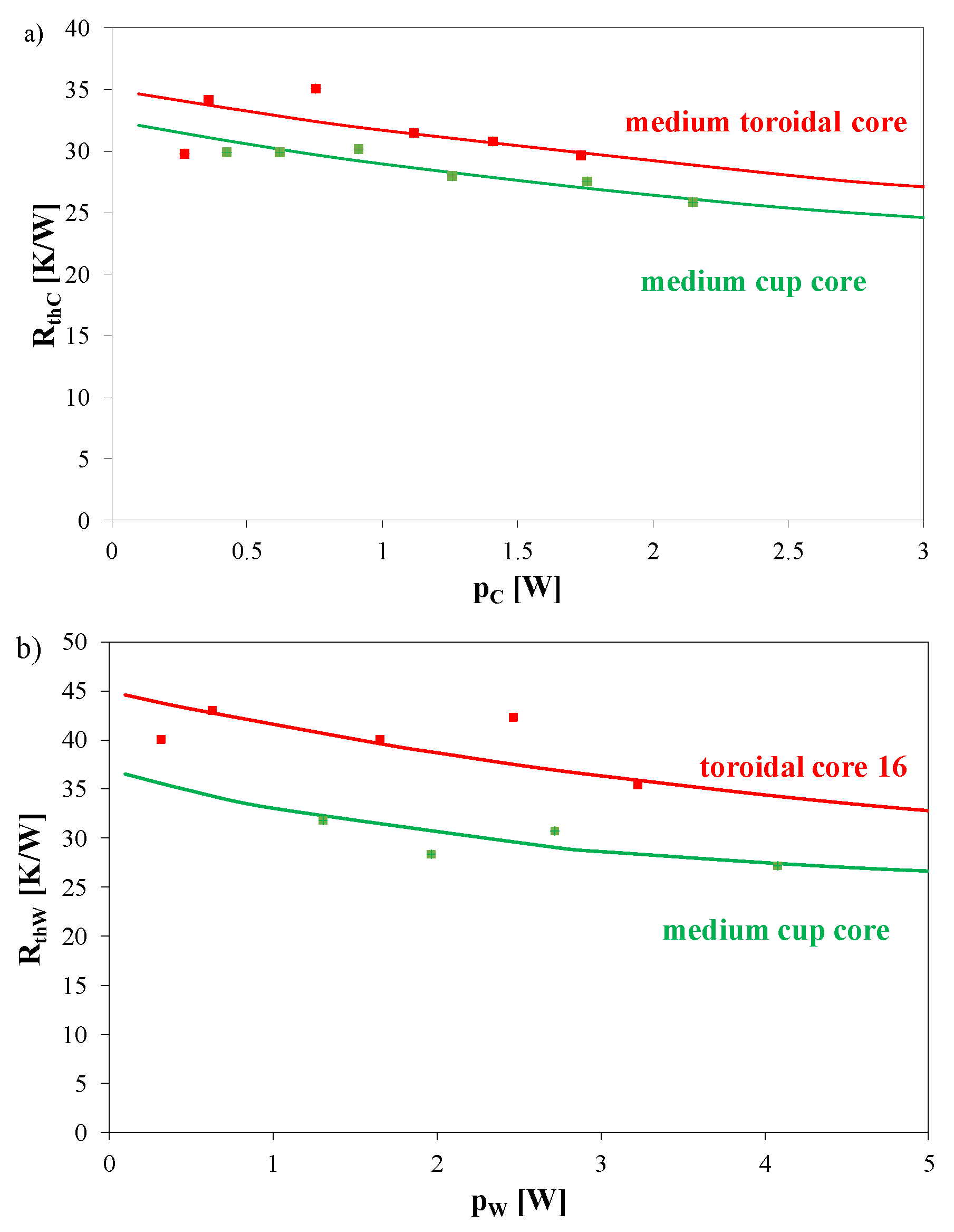
Figure 15) occurring in the thermal model of the considered inductors with cup cores and inductors with toroidal cores on power dissipated in these components of the inductor.
As can be seen in Figure 13, dependence RthC(pC) is a decreasing function for both the inductors with the cup cores (Figure 13a) and with the toroidal core (Figure 13b). It is also visible that as the core size increases, thermal resistance values decrease. The biggest differences in the values of this parameter for the considered cores can be seen in the range of low values of power pC. Differences between the calculation results and the measurement results do not exceed a dozen percent for the inductor with the cup core and do not exceed 8% for the inductor with the toroidal core.
Figure 14 presents the calculated and measured dependences of thermal resistance RthW of the winding of the considered inductors with cup cores (Figure 14a) and inductors with toroidal cores (Figure 14b) on power dissipated in these cores. Due to the limited size of the small core, it was impossible to wind eight turns of copper wire in enamel with a diameter of 1 mm on inductor cores, so in the following results, a comparison between the big and medium cup cores only are presented in Figure 13a.
The characteristics presented in Figure 14 have a similar shape as the characteristics presented in Figure 13. An increase in the core volume causes a decrease in thermal resistance of the winding. The differences between the results of measurements and calculations for inductors with the cup core do not exceed 10% for all the considered inductors with cup and toroidal cores. It is also worth noticing that thermal resistance of the inductor containing the toroidal core with the 16 mm diameter is higher by even 10 K/W than thermal resistance of the inductor containing the medium cup core. Additionally, the differences between the results of measurements and calculations do not exceed 11% for the inductor with the cup core and 15.5% for the inductor with the toroidal core.
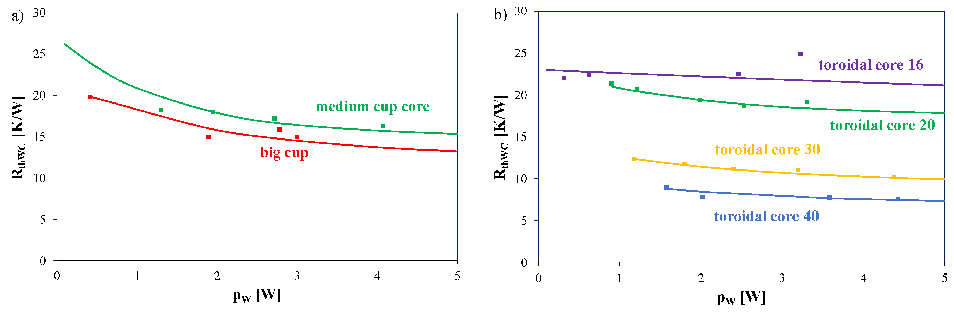
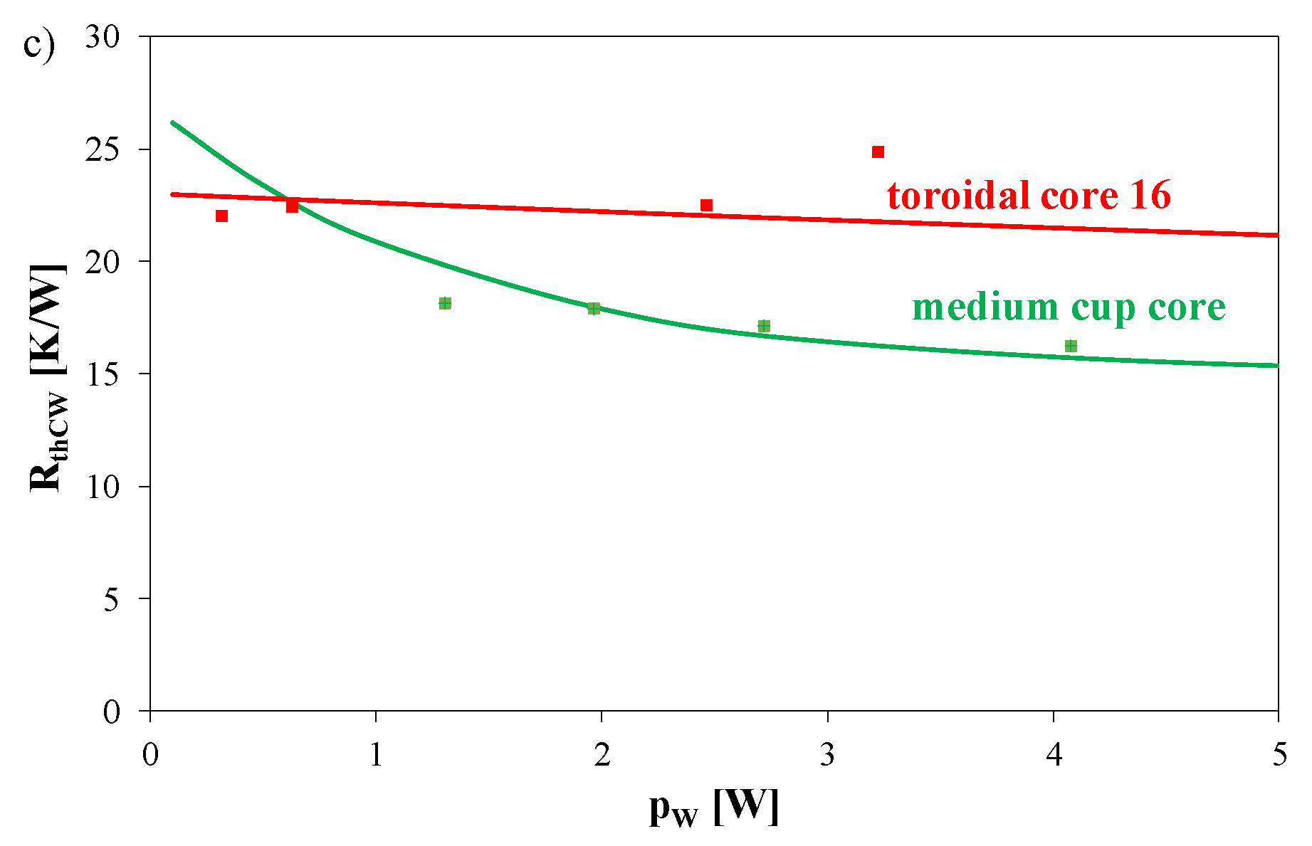
Figure 15 presents the calculated and measured dependences of mutual thermal resistance between winding and core RthWC of the inductors with cup cores (Figure 15a) and inductors with toroidal cores (Figure 15b) on power dissipated in these cores.
As can be seen, an increase of the core size causes a decrease of thermal resistance of the considered inductors with cup and toroidal cores. In the case of the inductor with the toroidal core an increase in diameter from 16 to 40 mm causes a more than double decrease of thermal resistance, whereas an increase of the diameter from 18 to 26 mm of the cup core causes a decrease in thermal resistance by about 15%. Differences between the calculations and measurements results do not exceed a dozen per cent for the inductor with the cup core and they do not exceed 13% for the inductor with the toroidal core.
Figure 16 presents the measured and calculated dependences of thermal resistances RthC, RthW and RthCW occurring in the nonlinear thermal model of the inductor on power dissipated in the core (Figure 16a) and in the winding (Figure 16b) for inductors with the medium cup core and the toroidal core 16. As mentioned in Section 3, both the considered cores have similar volume.
As can be seen, dependences of all the thermal resistances on power dissipated in the core are decreasing functions. Values of the considered parameters for the toroidal core are higher than the values obtained for the cup core. The highest values were obtained for thermal resistance of the winding RthW, and the lowest values for mutual thermal resistance between the core and the winding RthCW. Values of these parameters differ between each other even twice. Due to the influence of changes in power values in the considered range, changes in individual thermal resistances up to 20% are observed. Also, the good agreement between the results of calculations and measurements was obtained. The differences between the results of calculations and measurements are less than 12%.
Analysing results of investigation presented above we formulated the analytic Equation describing an influence of core volume on thermal resistances existing in the thermal model of the inductor. The form of this Equation is as follows:
R t h = R t h A ( 1 + k 1 e x p ( V e m 1 ) )
where RthA denotes border value of the thermal resistance at the volume of core tending to infinity, Ve is equivalent core volume, whereas m1 and k1 are model parameters characterising the slope of the dependence Rth(Ve).
In the same way, an analytical description of the dependence of thermal capacitance on core volume was formulated. This dependence is given by following Equation:
C t h = C t h A ( 1 + k 3 V e )
where CthA denotes border value of thermal capacitance corresponding to zero value of volume Ve, whereas k3 is volume coefficient of thermal capacitance.
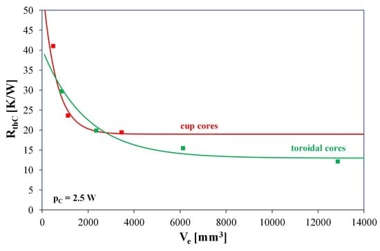
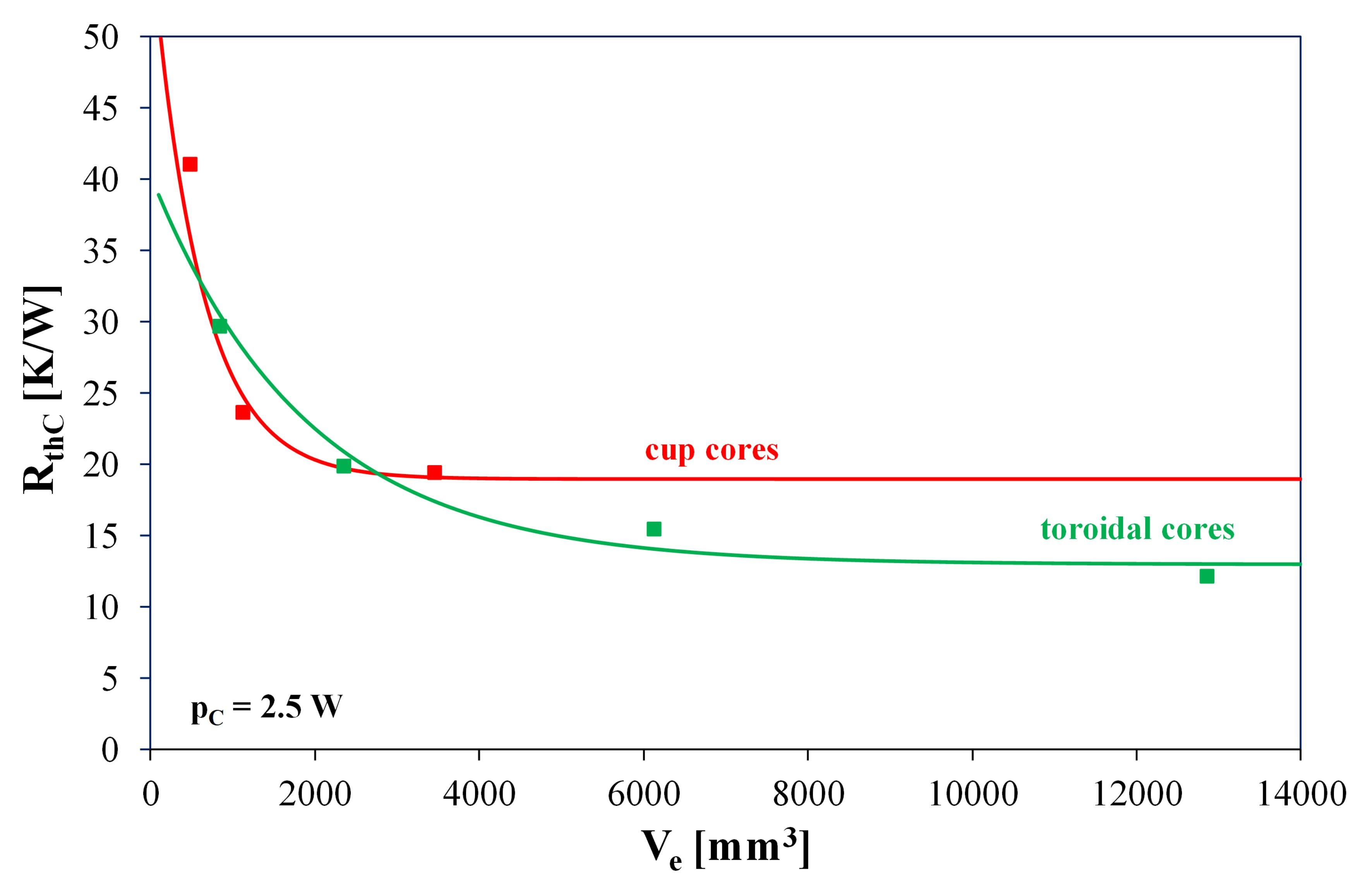
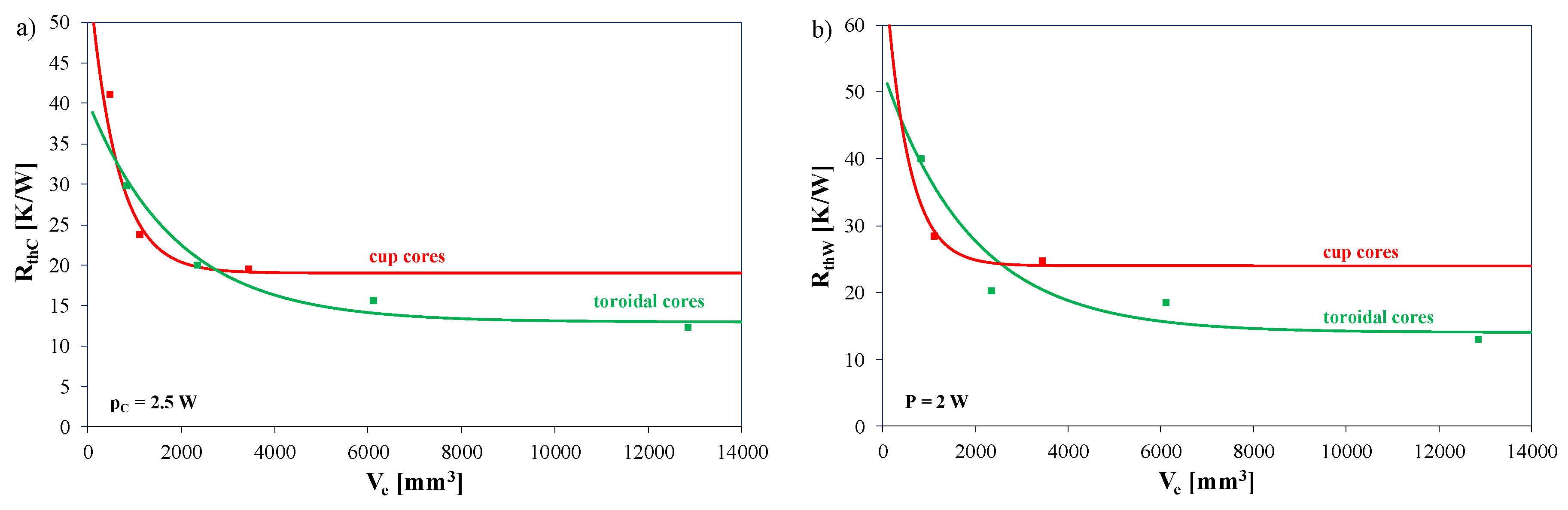
Figure 17 presents the measured (points) and calculated (lines) using Equation (8) dependences of thermal resistance of the core RthC, occurring in the nonlinear thermal model of the inductor on effective volume of the core for inductors with the cup cores (red colour) and the toroidal cores (green colours). Measurements and computations were performed at power dissipated in the core equal to 2 W.
As it is visible, for both the considered shapes of the core the dependence Rth(Ve) is a decreasing function. Values of both thermal resistances for cup cores are smaller than for toroidal core in the range of low values of core volume, whereas in the range of high values of core volume these relation is opposite. It is worth noticing that in the considered range of change the core volume values of thermal resistance decreases over twice. For both the shapes of core, a good accuracy of modelling considered dependences are obtained.
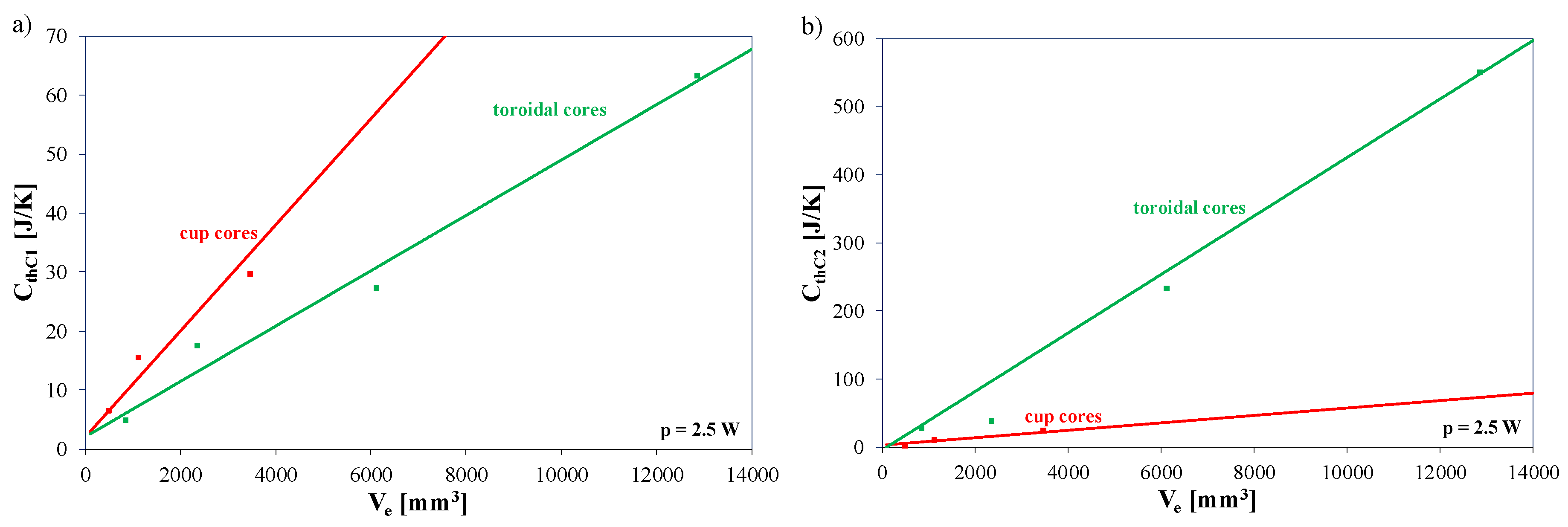
Figure 18 illustrates an influence of core volume on selected thermal capacitances occurring in thermal model of tested inductors.
As can be observed, the considered dependences are increasing functions. It is worth noticing that the thermal capacitance CthC1 of the tested inductors is smaller for inductors including toroidal cores, whereas the thermal capacitance CthC2 is smaller for inductors including cup cores. Also, the good agreement between the results of measurements and calculations was obtained. The differences between these results do not exceed 12% for both considered shapes of cores.

5. Conclusions

In the paper, a compact nonlinear thermal model of the inductor was proposed. This model makes it possible to calculate values of temperature of the core and the winding of the inductor taking into account occurrence of self-heating in every mentioned component of the inductor and mutual thermal couplings between the core and the winding. It also takes into account the influence of power dissipated in every component of the inductor on thermal resistance of the core and the winding and mutual thermal resistance between the core and the winding. A manner of calculating the value of parameters of this model was also proposed.
Correctness of the worked out model was verified for selected inductors containing ferrite cores made of the same ferrite material, but these cores were characterised by a different shape or by a different size. As a result of the comparison of the obtained results of calculations and measurements it was shown that the elaborated model is universal, i.e., it makes it possible to obtain the good agreement of these results over a wide range of changes of power dissipated in each component of the inductor at different shapes and dimensions of the core.
Comparing the findings obtained for different sizes of cup cores, it was observed that an increase in the dimensions of the core of the considered shape caused a decrease in the value of thermal resistance and extension of time indispensable to obtain the thermally steady state in the examined inductor. Taking into account the fact that a basic mechanism of removing heat generated in the core of the inductor is convection, it can be said that the value of thermal resistance of the core is a decreasing function of the surface of the cup core. Referring to the results of measurements shown in the paper [36] it can be stated that in the description of the considered dependence spatial orientation of the inductor should be also taken into account. In turn, the thermal capacitance of the core, deciding the time of settlement of the waveform of transient thermal impedance, depends on the volume of the ferrite core. Then, the thermal capacitances of the core can be described with an increasing function of the volume of the core.
The authors proposed analytical Equations describing dependences of thermal resistances and thermal capacitances of the core and the winding of the inductor on the volume of the core. Correctness of the formulated Equations was proved for both the considered shapes of cores and a good match between the results of measurements and calculations was obtained. The differences between the results of calculations and measurements do not exceed 15% maximum. The obtained results of calculations performed using the new thermal model of the inductor confirm usefulness of the formulated model.
A change in the shape of the core also influences waveforms of transient thermal impedances occurring in the new nonlinear compact thermal model of the inductor. At the similar volume of the core, greater even by 20% values of thermal resistance were obtained for the inductor with the cup core. The observed changes in the value of thermal resistances in the function of volume of the core are higher for inductors with cup cores than inductors with toroidal cores. From the thermal management point of view, it is more profitable to use toroidal cores than cup cores.
The obtained results of investigations make it possible to model the thermal properties of inductors in a simple way. The proposed thermal model of inductors can be used in power electronics applications. In the mentioned applications, properties of magnetic elements strongly influence watt-hour efficiency. Using the new model, the designers of power electronic circuits can calculate thermal parameters and temperature of every component of the designed inductor. They can also determine usefulness of selected inductors in the anticipated operating conditions of the designing step.
The results of investigations presented in this paper correspond to one ferromagnetic material only. In further investigations other ferromagnetic materials and other shapes of the cores will be analysed.

Author Contributions

Conceptualization, K.G.; methodology, K.G. and K.D.; measurements, K.D.; computations, K.G. and K.D.; resources, K.D.; writing—original draft preparation, K.G. and K.D.; writing—review and editing, K.G. and K.D.; visualization, K.G. and K.D.; supervision, K.G. All authors have read and agreed to the published version of the manuscript.

Funding

Project financed in the framework of the program by Ministry of Science and Higher Education called “Regionalna Inicjatywa Doskonałości” in the years 2019–2022, project number 006/RID/2018/19, the sum of financing 11,870,000 PLN.

Conflicts of Interest

The authors declare no conflict of interest.

Nomenclature

SymbolUnitExplanation
RthK/Wthermal resistance
N number of thermal time constant
τthisthermal time constants
ai coefficients whose sum has to be equal 1
ZthC(t)K/Wthermal impedance of the core
ZthW(t)K/Wthermal impedance of the winding
ZthCW(t)K/Wmutual thermal impedance between the core and the winding
pCWpower dissipated in the core
pWWpower dissipated in the winding
PvmW/cm3power losses per unit of volume in the core
Ta°Cambient temperature
TW°Cwinding temperature
TC°Ccore temperature
BsatTsaturation flux density
BRTremanence flux density
HCA/mcoercion magnetic force
µi initial permeability
lemmmagnetic path length
Vemm3volume of the core
Aemm2cross-section area of the core
RthAK/Wvalue of thermal resistance at the volume of the core tending to infinity
m1mm3model parameters characterising the slope of dependence Rth(Ve)
k1 model parameters characterising the slope of dependence Rth(Ve)
CthAJ/Kvalue of thermal capacitance corresponding to zero value of volume Ve
k3mm−3volume coefficient of thermal capacitance

References

  1. Barlik, R.; Nowak, M.; Grzejszczak, P.; Zdanowski, M. Estimation of power losses in a high-frequency planar transformer using a thermal camera. Arch. Electr. Eng. 2016, 65, 613–627. [Google Scholar] [CrossRef] [Green Version]
  2. Rashid, M.H. Power Electronic Handbook; Academic Press: Cambridge, MA, USA, 2007. [Google Scholar]
  3. Billings, K.; Morey, T. Switch-Mode Power Supply Handbook; McGraw-Hill: New York, NY, USA, 2011. [Google Scholar]
  4. Erickson, R.; Maksimović, D. Fundamentals of Power Electronics; Kluwer Academic Publisher: Norwell, MA, USA, 2001. [Google Scholar]
  5. Van den Bossche, A.; Valchev, V. Inductor and Transformers for Power Electronic; CRC Press: Boca Raton, FL, USA, 2005. [Google Scholar]
  6. Andreu, D.; Boucher, J.; Maxim, A. New SPICE behavioural macromodelling method of magnetic components including the self-heating process. In Proceedings of the IEEE Annual Power Electronics Specialist Conference PESC, Charleston, SC, USA, 27 June–1 July 1999; Volume 2, pp. 735–740. [Google Scholar]
  7. Allahbakhshi, M.; Akbari, A. An improved computational approach for thermal modeling of power transformers. Int. Trans. Electr. Energy Syst. 2014, 25, 1319–1332. [Google Scholar] [CrossRef]
  8. Wilson, P.R.; Ross, J.N.; Brown, A.D. Simulation of magnetic component models in electric circuits including dynamic thermal effects. IEEE Trans. Power Electron. 2002, 17, 55–65. [Google Scholar] [CrossRef]
  9. Kazimierczuk, M.K. High-Frequency Magnetic Components; Wiley: Hoboken, NJ, USA, 2014. [Google Scholar]
  10. Tumański, S. Handbook of Magnetic Measurements; CRC Press: Boca Raton, FL, USA, 2011. [Google Scholar]
  11. Detka, K.; Górecki, K. Modelling the power losses in the ferromagnetic materials. Mater. Sci-Pol. 2017, 35, 398–404. [Google Scholar] [CrossRef] [Green Version]
  12. Barlik, R.; Nowak, M. Energoelektronika Elementy Podzespoły Układy; Politechnika Warszawska: Warszawa, Poland, 2014. [Google Scholar]
  13. FERYSTER Sp. z o.o. Sp.k. Toroidal ferrite cores (RTF type). Available online: https://feryster.pl/rdzenie-rtf (accessed on 25 July 2020).
  14. Fiorillo, F.; Bertotti, G.; Appino, C.; Pasquale, M. Soft magnetic materials. In Wiley Encyclopedia of Electrical and Electronics Engineering; Webster, J.G., Ed.; Wiley: Hoboken, NJ, USA, 2016. [Google Scholar]
  15. Górecki, K.; Detka, K. Application of average electrothermal models in the SPICE-aided analysis of boost converters. IEEE Trans. Ind. Electron. 2018, 66, 2746–2755. [Google Scholar] [CrossRef]
  16. Górecki, K.; Detka, K. Influence of Power Losses in the Inductor Core on Characteristics of Selected DC–DC Converters. Energies 2019, 12, 1991. [Google Scholar] [CrossRef] [Green Version]
  17. Detka, K.; Gorecki, K.; Zarebski, J. Modeling single inductor DC–DC converters with thermal phenomena in the inductor taken into account. IEEE Trans. Power Electron. 2016, 32, 7025–7033. [Google Scholar] [CrossRef]
  18. Gorecki, K.; Gorski, K. Compact thermal model of planar transformers. In Proceedings of the 24th International Conference ”Mixed Design of Integrated Circuits and Systems”—Mixdes, 2017, Bydgoszcz, Poland, 22–24 June 2017; pp. 345–350. [Google Scholar]
  19. Benhadda, Y.; Hamid, A.; Lebey, T. Thermal modeling of an integrated circular inductor. J. Nano-Electron. Phys. 2017, 9, 01004-1–01004-5. [Google Scholar] [CrossRef]
  20. Castellazzi, A.; Gerstenmaier, Y.C.; Kraus, R.; Wachutka, G.K.M. Reliability analysis and modeling of power MOSFETs in the 42-V-PowerNet. IEEE Trans. Power Electron. 2006, 21, 603–612. [Google Scholar] [CrossRef] [Green Version]
  21. Narendran, N.; Gu, Y. Life of LED-Based White Light Sources. J. Disp. Technol. 2005, 1, 167–171. [Google Scholar] [CrossRef]
  22. Chang, M.-H.; Das, D.; Varde, P.V.; Pecht, M. Light emitting diodes reliability review. Microelectron. Reliab. 2012, 52, 762–782. [Google Scholar] [CrossRef]
  23. Górecki, K.; Gorecki, P.; Zarebski, J. Measurements of parameters of the thermal model of the IGBT module. IEEE Trans. Instrum. Meas. 2019, 68, 4864–4875. [Google Scholar] [CrossRef]
  24. Bagnoli, P.E.; Casarosa, C.; Ciampi, M.; Dallago, E. Thermal resistance analysis by induced transient (TRAIT) method for power electronic devices thermal characterization—Part I: Fundamentals and theory. IEEE Trans. Power Electron. 1998, 13, 1208–1219. [Google Scholar] [CrossRef]
  25. Sofia, J.W. Analysis of thermal transient data with synthesized dynamic models for semiconductor devices. IEEE Trans. Compon. Packag. Manuf. Technol. Part A 1995, 18, 39–47. [Google Scholar] [CrossRef]
  26. Masana, F.N. Extraction of structural information from thermal impedance measurements in time domain. In Proceedings of the 18th International Conference Mixed Design of Integrated Circuits and Systems, MIXDES 2011, Gliwice, Poland, 16–18 June 2011; pp. 398–402. [Google Scholar]
  27. D’Alessandro, V.; Rinaldi, N. A critical review of thermal models for electro-thermal simulation. Solid-State Electron. 2002, 46, 487–496. [Google Scholar] [CrossRef]
  28. Yener, Y.; Kakac, S. Heat Conduction; Taylor & Francis: Boca Raton, FL, USA, 2008. [Google Scholar]
  29. Székely, V. A new evaluation method of thermal transient measurement results. Microelectron. J. 1997, 28, 277–292. [Google Scholar] [CrossRef]
  30. Górecki, K.; Zarębski, J. Nonlinear compact thermal model of power semiconductor devices. IEEE Trans. Components Packag. Technol. 2010, 33, 643–647. [Google Scholar] [CrossRef]
  31. Janicki, M.; Torzewicz, T.; Samson, A.; Raszkowski, T.; Napieralski, A. Experimental identification of LED compact thermal model element values. Microelectron. Reliab. 2018, 86, 20–26. [Google Scholar] [CrossRef]
  32. Górecki, K. Modelling mutual thermal interactions between power LEDs in SPICE. Microelectron. Reliab. 2015, 55, 389–395. [Google Scholar] [CrossRef]
  33. Górecki, K.; Detka, K.; Górski, K. Compact Thermal model of the pulse transformer taking into account nonlinearity of heat transfer. Energies 2020, 13, 2766. [Google Scholar] [CrossRef]
  34. Janicki, M.; Torzewicz, T.; Ptak, P.; Raszkowski, T.; Samson, A.; Górecki, K. Parametric Compact Thermal Models of Power LEDs. Energies 2019, 12, 1724. [Google Scholar] [CrossRef] [Green Version]
  35. Gorecki, K.; Gorecki, P. A new form of the non-linear compact thermal model of the IGBT. In Proceedings of the 12th IEEE International Conference on Compatibility, Power Electronics and Power Engineering, Doha, Qatar, 10–12 April 2018. [Google Scholar] [CrossRef]
  36. Górecki, K.; Górski, K.; Zarębski, J. Investigations on the influence of selected factors on thermal parameters of impulse-transformers. Inf. MIDEM-J. Microelectron. Electron. Compon. Mater. 2017, 47, 3–13. [Google Scholar]
  37. Górecki, K.; Detka, K.; Górski, K. The nonlinear compact thermal model of the pulse transformer. In Proceedings of the 25 International Workshop on Thermal Investigations of ICs and Systems Therminic 2019, Lecco, Italy, 25–27 September 2019. [Google Scholar] [CrossRef]
  38. Ptak, P.; Górecki, K.; Dziurdzia, B. Modelling thermal properties of large LED modules. Mater. Sci. 2019, 37, 628–638. [Google Scholar]
  39. Christiaens, F.; Vandevelde, B.; Beyne, E.; Mertens, R.; Berghmans, J. A generic methodology for deriving compact dynamic thermal models, applied to the PSGA package. IEEE Trans. Compon. Packag. Manuf. Technol. 1998, 21, 565–576. [Google Scholar] [CrossRef]
  40. Górecki, K.; Krac, E. Measurements of thermal parameters of solar modules. J. Physics Conf. Ser. 2016, 709, 012007. [Google Scholar] [CrossRef] [Green Version]
  41. Zarębski, J.; Górecki, K. Parameters estimation of the d.c. electrothermal model of the bipolar transistor. Int. J. Numer. Model. Electron. Netw. Devices Fields 2020, 15, 181–194. [Google Scholar] [CrossRef]
  42. Górecki, K.; Zarębski, J.; Górecki, P.; Ptak, P. Compact thermal models of semiconductor devices—A review. Int. J. Electron. Telecommun. 2019, 65, 151–158. [Google Scholar]
  43. Optex Product Information. Available online: http://www.dewetron.cz/optex/katlisty/PT-3S.pdf (accessed on 25 July 2020).
  44. F867 Material Characteristics. Available online: http://sklep.remagas.pl/images/Właściwości_materiału_F-867.pdf (accessed on 25 July 2020).
Figure 1. Nonlinear compact thermal model of the inductor.
Energies 13 03842 g001
Figure 2. Set-up to measure thermal parameters of the inductor.
Energies 13 03842 g002
Figure 3. Dimensions of the investigated (a) cup core and (b) toroidal core.
Energies 13 03842 g003
Figure 4. Tested inductors containing cup cores of different dimensions.
Energies 13 03842 g004
Figure 5. Tested inductors containing toroidal cores.
Energies 13 03842 g005
Figure 6. Measured and calculated waveforms of transient thermal impedance of the core for inductors with (a) cup and (b) toroidal cores of different dimensions.
Energies 13 03842 g006
Figure 7. Measured and calculated waveforms of transient thermal impedance of the winding for inductors with (a) cup and (b) toroidal cores.
Energies 13 03842 g007
Figure 8. Measured and calculated waveforms of transient thermal impedance of the medium cup core at selected values of dissipated power.
Energies 13 03842 g008
Figure 9. Measured and calculated waveforms of transient thermal impedances of the inductor containing the toroidal core 16.
Energies 13 03842 g009
Figure 10. Measured and calculated waveforms of transient thermal impedances of the inductor containing the medium cup core.
Energies 13 03842 g010
Figure 11. Measured and calculated waveforms of transient thermal impedances of the inductor containing the toroidal core 16.
Energies 13 03842 g011
Figure 12. Measured and calculated waveforms of transient thermal impedances of the core (a) and of the winding (b) for inductors containing each considered core.
Energies 13 03842 g012
Figure 13. Measured and calculated dependences of thermal resistance RthC of inductors with (a) cup cores and (b) toroidal core on dissipated power in the core.
Energies 13 03842 g013
Figure 14. Measured and calculated dependences of thermal resistance RthW of inductors winding with (a) cup cores and (b) toroidal core on dissipated power in the winding.
Energies 13 03842 g014
Figure 15. Measured and calculated dependences of thermal resistance RthW of inductors with (a) cup cores and (b) toroidal core on dissipated power in the winding.
Energies 13 03842 g015
Figure 16. Measured and calculated dependences of thermal resistances (a) RthC, (b) RthW and (c) RthCW of inductors with the medium cup core and the toroidal core on power dissipated in the core.
Energies 13 03842 g016aEnergies 13 03842 g016b
Figure 17. Measured and calculated dependences of thermal resistance of the core RthC (a) and thermal resistance of the winding RthW (b) on the effective volume of the core for inductors with cup cores and toroidal cores.
Energies 13 03842 g017
Figure 18. Measured and calculated dependences of selected thermal capacitance of the core CthC1 (a) and CthC2 (b) on the effective volume of the core for inductors with cup cores and toroidal cores.
Energies 13 03842 g018
Table 1. Values of selected parameters of material F867 [43].
ParameterBsat (T)BR (T)HC (A/m)µiPv (mW/cm3)
Value (25 °C)0.60.15402400129
Value (100 °C)0.40.1240390070
Table 2. Geometrical parameters of the tested inductor cores.
Cup Core
Dimensions (mm)le (mm)Ae (mm2)Ve (mm3)
Ø1h
14820.623.1485
181125.9431120
261637.2933460
Toroidal Core
Dimensions (mm)le (mm)Ae (mm2)Ve (mm3)
Ø1Ø2h
169.56.540.0321.12845.71
20101035.71502355
31191378.5786123
40241598.5644812861
Table 3. Values of parameters of the nonlinear thermal model of inductors with the medium cup core and with the toroidal core.
ParameterRth0 (K/W)Rth1 (K/W)b (W)a1a2Cth1 (J/K)Cth2 (J/K)
Inductor with the Medium Cup Core
ZthW(t)251120.4030.5972.4038.07
ZthC(t)191520.4490.55110.69423.693
ZthWC(t)15121.40.9370.06313.99219.56
Inductor with the Toroidal Core 16
ZthW(t)25205.30.260.740.5164.958
ZthC(t)201540.9940.0065.132151.47
ZthWC(t)158190.9060.0947.60553.85
Table 4. Values of parameters describing ZthC(t) of inductors with cup cores.
ParameterRth0 (K/W)Rth1 (K/W)b (W)a1a2Cth1 (J/K)Cth2 (J/K)
Small core38330.50.350.651.1146.503
Medium core201540.4490.55111.60125.172
Big core161010.0230.97727.17229.228
Table 5. Values of parameters describing ZthW(t) of inductors with cup cores.
ParameterRth0 (K/W)Rth1 (K/W)b (W)a1a2Cth1 (J/K)Cth2 (J/K)
Medium core251120.3190.6812.4989.620
Big core75020.390.613.16419.043
Table 6. Values of parameters describing ZthC(t) of inductors with toroidal cores of different dimensions.
ParameterRth0 (K/W)Rth1 (K/W)b (W)a1a2Cth1 (J/K)Cth2 (J/K)
toroidal core 16241320.9940.0064.7927.07
toroidal core 2019.65.510.8740.12617.53028.43
toroidal core 3011.87.93.30.980.0227.265233.12
toroidal core 4011610.9840.01663.356550.80
Table 7. Values of parameters describing Zthw(t) of inductors with toroidal core.
ParameterRth0 (K/W)Rth1 (K/W)b (W)a1a2Cth1 (J/K)Cth2 (J/K)
toroidal core 1625205.30.260.740.5164.958
toroidal core 2019.471.20.1790.8211.87818.976
toroidal core 3011.87.93.30.1920.8085.65027.265
toroidal core 408241.30.2750.7254.38344.125

