Abstract
There is a significant interaction between wind and earthquakes for large-scaled wind turbines due to an aeroelastic effect. This study evaluates the accuracy of an uncoupled method extensively utilized to analyze the seismic response of wind turbines at the operational state. Initially, the oscillation of the blade for the National Renewable Energy Laboratory (NREL) 5 MW wind turbine excited by wind and wind-earthquake combination, respectively, is compared using the fully coupled method to verify the assumption in this uncoupled method. Subsequently, the influence of ground motions on the aerodynamic loadings of the rotor is discussed to evaluate the interaction between wind and earthquake loads. In addition, the accuracy of the uncoupled method is assessed by comparing the analysis results of the coupled and uncoupled methods, where different mean wind speed and equivalent aerodynamic damping ratio are considered. The results indicate that the oscillation velocity of blades and thrust on the rotor are significantly influenced by ground motions. Moreover, the amplitude of thrust variations caused by earthquakes increases monotonously with the oscillation velocity amplitude of blade-root. The errors between the two models are beyond the engineering margins for some earthquakes, such that it is difficult to optimize a consistent aerodynamic damping in the uncoupled model to accurately predict the seismic response of wind turbines.
1. Introduction
As the primary form of wind energy utilization, wind power can fulfill the global energy demand and reduce CO2 emissions [1]. The global annual installations of wind turbines have been more than 50 GW since 2014, and it will be nearly 71 GW until 2024 [2]. With more and more wind turbines being built in seismically active regions [3], it is necessary to accurately predict the seismic response of wind turbines for assessment and design purposes. The large-scaled wind turbine is a high-slender structure and sensitive to the loadings in the lateral directions. Consequently, the updated specifications [4,5] recommended that earthquake forces should be combined with aerodynamic loadings induced by the normal wind condition, where the analysis methods can be divided into coupled and uncoupled.
The coupled analysis of the seismic response of wind turbines was firstly performed by the GH BLADED software [6]. The aerodynamic loadings were calculated by blade element momentum (BEM) theory, and the simulation results indicated that the aeroelasticity of the wind turbine and influence of the controller could be modeled with this code. Subsequently, the seismic module was added to the FAST (Fatigue, Aerodynamics, Structures, and Turbulence) code, an open-source software, such that the coupled analysis of wind and earthquake loads could be performed by this code [7]. Immediately, the reliability of this code was validated by seismic vibration table tests and numerical simulations [8]. As the FAST code could be developed by the users, it was widely used to explore the dynamic behavior of wind turbines experiencing wind and earthquake loads [9,10]. With this code, the dynamic response of the National Renewable Energy Laboratory (NREL) 5 MW wind turbine excited by wind and earthquake loads was investigated, and the results revealed the fundamental role of seismic loads in the reliability and economics of wind turbines [11]. The aerodynamic damping effect of wind on the seismic response of wind turbines was studied using the FAST code [12,13]. The coupled analysis was also performed by user-developed codes and these studies [14,15,16,17] emphasized the necessity of the coupled method predicting the seismic response of wind turbines. Furthermore, the interaction between wind and earthquake loads was also revealed by the model test [18]. However, the computational costs of the coupled method may be significant due to the randomness of wind and earthquakes, and the existing aeroelastic code for wind turbines had very limited ability to model the support structure and foundation. These shortcomings of the coupled method promoted the development of the uncoupled analysis method.
Actually, the uncoupled method was utilized to analyze the seismic response of wind turbines at the operational state earlier than the coupled method. In the preliminary stage, the aerodynamic loadings on the rotor were modeled as a static force acting at the tower top where a concentrated mass replaced the rotor-nacelle-assembly (RNA) [19]. With this method, seismic responses of wind turbines excited by wind and earthquake were analyzed [20,21], and the dominant role of earthquake load in high-seismic hazard regions was emphasized by using the deterministic analysis [22] and probabilistic analysis [23]. Though the interaction between wind and earthquake was not considered in these studies, the attention of researchers to the anti-seismic wind turbine was attracted. Subsequently, according to the BEM theory, the aerodynamic loadings on the rotor were divided into the mean and fluctuating thrust, where the latter was related to aeroelastic damping [24]. The wind–earthquake interaction was simulated by equivalent aerodynamic damping, and the simulation indicated that the response of the tower caused by a weak earthquake was more significant than that induced by wind loading.
As the large-scaled wind turbines are used in onshore and offshore wind farms, the blade is becoming more flexible. According to the reference [25], the maximum oscillation velocity of the blade tip normal to the chord will be as high as 6 m/s when the displacement amplitude is 1 m. This value can directly be compared with the variations of inflow speed, such that the aerodynamic loadings on the rotor should be computed by an aeroelastic tool [26]. For the multi-megawatt wind turbines, the comparison on structural models of the RNA indicated that higher modes were essential for the seismic response of the system [27]. As the lack of details for the blade, the beam element was usually adopted to model the rotor of wind turbines [28,29]. On the basis of these studies, an improved uncoupled method was proposed [30], where the aerodynamic forces of the blade nodes for each time step were computed by the AeroDyn code and the structural model of the wind turbine is established by the commercial finite element software ABAQUS. An equivalent aerodynamic damping ratio of 4% for the first two fore-aft (FA) tower modes was added to the structural damping to contain the interaction between wind and earthquake. This method was initially used to evaluate the seismic fragility of the NREL 5 MW wind turbine for different mean wind speeds. Immediately, this method was implemented in the GH BLADED software and assessed by comparisons between the coupled and uncoupled analysis results [31,32,33]. Besides, the uncoupled analysis was also performed in ABAQUS where aerodynamic loading was computed by the BEM theory and the average pitch angle was used to consider the effect of pitch regulation [34,35]. The uncoupled analysis method proposed by Asareh et al. determined the aerodynamic loading on the rotor using the aeroelastic code and could be directly implemented in the commercial software with high efficiency. Therefore, it has been widely used to analyze the seismic response of wind turbines [36,37].
Though comparisons between the coupled and uncoupled method were performed by Santangelo et al., the assumptions of the uncoupled method have not been illustrated and evaluated, and the input ground motions were limited. This study aims to further evaluate the uncoupled analysis method for the seismic response of wind turbines at operational condition. First, the numerical model of simulations and assumptions of the uncoupled method are illustrated in detail. Next, the oscillation velocity of blades and aerodynamic loading on the rotor are investigated to evaluate the interaction between wind and earthquake load. Finally, the seismic response of the NREL 5 MW wind turbine analyzed by the coupled and uncoupled methods are compared for different mean wind speed at hub height.
2. Numerical Modeling
The reference 5 MW wind turbine created by the NREL was taken as the research object, and its dimensions are shown in Figure 1. The main specifications of this turbine are listed in Table 1, and the details can be found in an existing report [38]. The natural frequencies of the NREL 5 MW wind turbine obtained from this design report are listed in Table 2. The tower is divided into 50 beam elements of the same length. The blade shown in Figure 2 is discretized into 17 beam elements with the following length distribution: 2.73 m for the first three elements, 4.1 m for the next eleven elements, and 2.73 m for the remaining three elements. The FAST code [39] is used to analyze the seismic response of the NREL 5 MW wind turbine.
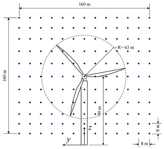
Figure 1.
Dimensions of numerical model.

Table 1.
Properties of National Renewable Energy Laboratory (NREL) 5-MW Wind Turbine.
Table 2.
Frequencies of the NREL 5 MW wind turbine.
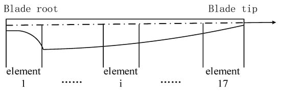
Figure 2.
Element distribution of the blade.
2.1. Wind Field
The fluctuating wind velocity was assumed to be a stationary, random vector field. The Kaimal spectrum is used to describe the turbulent characteristic of wind process:
where f is the frequency (Hz); Vhub is the average wind speed of hub-height; and are the standard deviation and integral scale parameter for every velocity component, respectively, in which the subscript k refers to the component along the x-, y-, and z-axes. According to IEC 61400-1 [4], the power law is adopted to determine the wind profile, where the exponent is 0.2. The IEC turbulence level B is selected to determine all the parameters.
The cross power spectra density function between nodes i and j is defined as:
where Si,i and Sj,j denote the wind velocity auto spectra at nodes i and j, respectively; is the coherence function defined in Equation (3).
where Δr is the distance of the two nodes, b represents the coherence decrement, with a value of 12 for this study; LC represents the coherence scale parameter, with a value of 340.2 m according to IEC 61400-1 [4].
The TurbSim code [40] is utilized to generate the full-field wind samples with random seeds. The duration of the wind speed time-history is 650 s to cover the simulations. As shown in Figure 1, the wind field is discretized into a 160 m × 160 m vertical rectangle grid to encompass the entire rotor. The distance between adjacent nodes is 8 m in both the horizontal and vertical directions.
2.2. Earthquake Load
The earthquake has three components, and their relationship is stochastic. Therefore, some researchers selected one component to analyze the seismic response of wind turbines [12,41]. The difference between the coupled and uncoupled methods lies in the solving method of the aeroelastic effect. Under the excitation of wind, the aerodynamic loading in the FA direction is more significant than that of the side-to-side (SS) direction [11], such that the aeroelasticity is mainly in the FA direction of wind turbines. To eliminate the influence of earthquake forces in the SS direction, one of the two horizontal components of earthquakes which will cause larger a tower-base bending moment is selected as the input ground motion and applied along the FA direction of the wind turbine. The studies conducted by Santangelo et al. [31,32,33] indicated that the error between the coupled and uncoupled methods was related to earthquakes. Consequently, a set of earthquakes shown in Table 3 are selected from the database of Pacific Earthquake Engineering Research center (PEER) to evaluate the uncoupled model thoroughly, where the far field and near field records recommended by Federal Emergency Management Agency (FEMA) [42] are included. For Table 3, the component row lists the horizontal component of earthquakes selected in this study.
Table 3.
Details of input ground motions obtained from Pacific Earthquake Engineering Research (PEER) database.
The FAST code [43] can input the ground motion for the tower base through the damped oscillator or large mass method. For the damped oscillator method, spring and damper were added to the tower base, and then the system was considered as a damped oscillator. The actuator frequency should be approximately 10 times the highest frequency of the turbine model when excited, which indicates that the time step was quite small and the numerical simulation might be unstable if the input ground motion includes impulse. Therefore, the large mass method [44] was employed to input the ground motion for the tower base in the present study. An artificially large mass is added to the tower base according to the large mass method, and a concentrated force is applied at the tower base to produce the desirable ground motion:
where M is the artificially large mass; m represents the mass of NREL 5MW wind turbine and is 697 460 kg; and, a(t) is the acceleration time history of the input ground motion. Referring to the literature [44,45], the large mass M is set as 7 × 10⁹, which is 10,000 times larger than the mass of NREL 5MW wind turbine.
2.3. Coupled and Uncoupled Methods
As shown in Figure 3, the rotor of the wind turbine is subjected to turbulent wind and rotating with an angular velocity . When the rotor oscillates in the FA direction of the wind turbine, the blade element with radius r and length dr experiences an aerodynamic loading dT, which can be expressed as:
where ρ is the density of air; CL and CD are the lift coefficients and drag coefficients, respectively; φ is the local inflow angle; α is the local angle of attack (AOA); is the full-span pitch angle; and is the aerodynamic twist of blades; and are the tangential induction factor and axial induction factor, respectively; VW is the wind speed; is the oscillation velocity of the blade in the FA direction of the wind turbine.
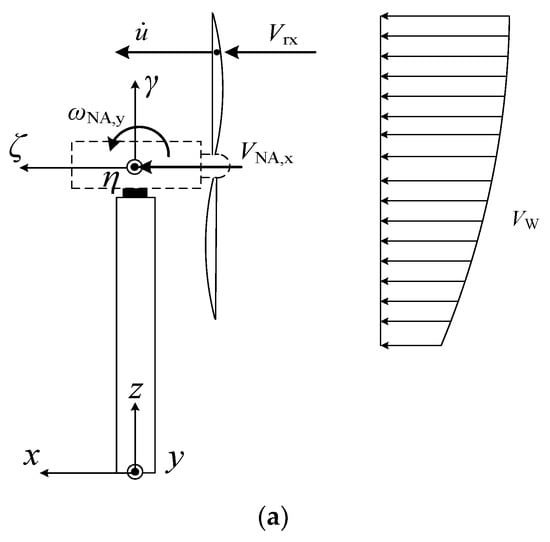
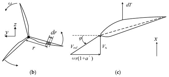
Figure 3.
Analysis model of statics and kinematics; (a) Whole model, (b) Rotor, (c) Cross section of blade.
According to Equations (5)–(9), the oscillation velocity of the blade influences the aerodynamic loadings on the rotor, such that the seismic response of wind turbines subjected to wind and earthquake loads is a typical aeroelastic problem. Moreover, modern wind turbines widely adopted variable speed and pitch regulation technology [46]. Therefore, the aero-servo-elastic coupling effect should be considered when predicting the dynamic response of wind turbines. In the coupled method, Equqtions (5)–(9) should be solved with the equation of motion of the dynamic system which is derived using the Kane method in the FAST code. The analysis results obtained by the coupled method are taken as the benchmark to evaluate the accuracy of the uncoupled method.
The total oscillation velocity of the blade can be divided into:
where and are the vibration velocity of the blade induced by wind and earthquake, respectively. For the large-scale wind turbines, the oscillation velocity of the blade caused by wind can directly be compared with the variations of inflow speed [25]. Assuming is small compared to the wind speed, the aerodynamic loadings on the blade can be decoupled through a first-order Taylor expansion:
where represents the aerodynamic loadings on the blade excited by wind; is the increment of the aerodynamic loading caused by earthquakes and indicates damping effect on the wind turbine.
By Equation (11), the dynamic response of wind turbines excited by wind and earthquake can be decoupled. Though not mentioned in their papers, the uncoupled method proposed by Asareh et al. [30] and utilized by other researchers [31,32,33,34,35,36,37] was based on Equation (11). In this uncoupled method, the responses of wind turbines induced by wind and earthquake, respectively, are calculated initially, and they are linearly combined subsequently. The rotor is spinning under the wind excitation, while it is in the parked state for earthquake excitation only. In order to represent the wind–earthquake interaction, an equivalent aerodynamic damping ratio should be explicitly added to the wind turbines in the uncoupled method [47]. However, there has been a debate on the aerodynamic damping of wind turbines until now [47,48,49]. Consequently, the aerodynamic damping ratios in the uncoupled method are selected in a wide range for two purposes. Firstly, it is to cover the real value of aerodynamic damping. Secondly, it is attempted to determine the optimal aerodynamic damping ratio, which can maintain the accuracy of the uncoupled model for all the earthquakes and response quantities. Therefore, the equivalent aerodynamic damping ratio varies within the interval 0–10% at steps equal to 1.0% in this study. Moreover, the existing aerodynamic damping theory only considers the first FA tower mode. According to the suggestions of Asareh et al. [30], it is assumed that the aerodynamic damping of the first two FA tower modes of wind turbines is equal, which was also adopted by other researchers [31,32,33].
3. Vibration and Aerodynamic Loadings on the Rotor
The aeroelasticity of wind turbines is associated with the oscillation velocity of the blade in the FA direction. First, the oscillation velocity of blades under the excitation of wind only and wind-earthquake combination was analyzed using the fully coupled method where the average wind speed of hub-height was set to 11.4 m/s. Next, the influence of earthquakes on the aerodynamic loadings on the rotor were evaluated. Considering the symmetry of blades, the kinematic analysis was performed for the blade 1. In all the following simulations, the duration and time step were set as 600 s and 0.002 s, respectively.
3.1. Oscillation Velocity of the Blade in the FA Direction
3.1.1. Excited by Wind
As shown in Figure 3, two coordinate systems were introduced to analyze the vibration of the blade. The x, y, z coordinate system fixed at the ground is a static frame of reference, with the x-axis increasing downwind along the FA direction of the wind turbine. The ξ, η, γ coordinate system, fixed on the nacelle, translates and rotates concerning the x, y, z system. The coordinate of the origin of this moving frame is (0, 0, 90) in the x, y, z system. According to the kinematic theory [50], the absolute velocity of the blade along the x-axis, , can be expressed as:
where is the relative velocity of the blade along the x-axis concerning the ξ, η, γ frame; is the absolute velocity of the origin of ξ, η, γ frame along the x-axis, is the angular velocity of ξ, η, γ frame about the y-axis, r is the radius of the section from the hub, is the azimuth angle of the blade. According to their definition, and are the translational velocity in the x-axis and angular velocity about the y-axis of the nacelle, respectively. In Equation (12), the term represents the motion of ξ, η, γ frame observed from the fixed x, y, z frame and is referred to as transport velocity.
The relative and transport velocity are caused by the deformation of the blade and support structure, respectively. Consequently, the absolute velocity of the blade is associated with the deformation of the blade and support structure. In the existing aerodynamic damping models of wind turbine towers [47,48,49], the blades were modeled as rigid and it is assumed that the motion of the entire rotor is consistent with that of the tower top but not rotation. According to Equation (12), the absolute velocity of the rigid blade along the x-axis is identical to the transport velocity. Therefore, only if the angular velocity of the nacelle is small will the oscillation velocity of the blade meet the assumption in aerodynamic damping models.
Figure 4 is the time history of wind speed at the hub height. When the NREL 5 MW wind turbine was excited by this wind sample, the translational velocity and angular velocity of the nacelle were recorded and are shown in Figure 5, and their amplitudes were 0.15 m/s and 0.003 rad/s, respectively. Obviously, the oscillation velocity of the nacelle excited by this wind sample was small enough to guarantee the serviceability of the wind turbine.
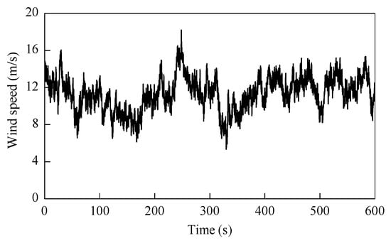
Figure 4.
Wind speed time history at the hub height of the wind turbine.
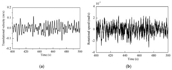
Figure 5.
Oscillation velocity of the nacelle subjected to turbulent wind; (a) translational velocity in the x-axis, (b) angular velocity in the y-axis.
The oscillation velocity of the blade in the x-axis excited by this wind sample is displayed in Figure 6. As shown in Figure 6a, the transport velocity of the blade tip was less than 0.2 m/s, which indicates the support structure has little contribution to the blade-tip velocity. From Figure 6b, the amplitude of relative velocity for the blade tip was 3.5 m/s, which was much larger than the transport velocity. Consequently, the absolute velocity of the blade tip depended on the deformation of the blade, and it was similar to the relative velocity of blade tip. The amplitudes of oscillation velocity for the blade are shown in Figure 6d, where Vax and Vex are the amplitude of the absolute velocity and transport velocity, respectively. As the angular velocity of the nacelle was small, the transport velocity amplitude of the blade was almost constant, which meets the assumption of the vibration velocity of the blade in the existing aerodynamic damping theory for wind turbine towers.
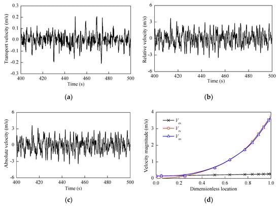
Figure 6.
Oscillation velocity of blade 1 along the x-axis; (a) transport velocity of blade tip, (b) relative velocity of blade tip, (c) absolute velocity of blade tip, (d) velocity amplitude of blade.
The version 13 of AeroDyn_code (NREL, Golden, CO, USA) [51], the aerodynamic module of FAST, output the aerodynamic loadings on blade 1. However, the local wind speed on the rotor disk was different because of the wind shear, which led to the aerodynamic loadings on the three blades not being identical. The necessary modifications were made for AeroDyn to output the aerodynamic loadings on the three blades, and the aerodynamic thrust, F, was the resultant force of aerodynamic loadings on the three blades in the x-axis:
where l is the index of the blade. As shown in Figure 7, the amplitude of thrust in this example was 0.8 MN and the mean was 0.6 MN, where the aeroelastic effect was considered.
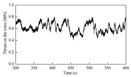
Figure 7.
Thrust on the rotor when the mean wind speed at hub height is 11.4 m/s.
3.1.2. Excited by Wind and Earthquake
The dynamic response of the wind turbine experiencing wind and earthquake loads is discussed using the coupled method in this section. To eliminate the initial transient behavior, the earthquake began at the 400th second in the following sections. The seismic response of the wind turbine subjected to a single wind–earthquake event was analyzed to obtain preliminary insight into its dynamic behavior. Considering that the spectral characteristics of seismic records 3 and 4 in Table 3 are typical, they were taken as the input ground motions, respectively. Their acceleration time history, response spectrum, and power spectrum are shown in Figure 8, where T1 and T2 represent the period of the first and second FA tower modes, respectively. The seismic record 3 had abundant high-frequency content, where the peak period of acceleration response spectrum was approximately identical to the second FA tower mode period, i.e., T2. Therefore, the high-order modes of the wind turbine may be significantly stimulated under the excitation of seismic record 3. For seismic record 4, its peak period of the power spectrum was close to the fundamental period of tower. Combining the two seismic records with the wind field in Section 3.1.1, respectively, the seismic response of the wind turbine was analyzed.
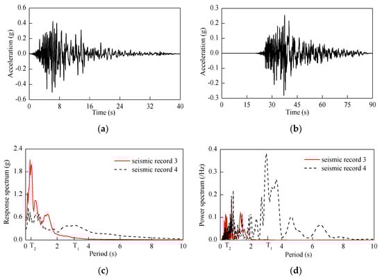
Figure 8.
Time history and spectral characteristic of seismic records 3 and 4; (a) acceleration time history of Record 3, (b) acceleration time history of Record 4, (c) acceleration response spectrum, (d) power spectrum.
First, the oscillation velocity of the nacelle is shown in Figure 9 when the input ground motion is seismic record 3. The translational velocity amplitude of the nacelle along the x-axis was 0.5 m/s which was 2.5 times larger than that induced by the wind only. The angular velocity amplitude of the nacelle about the y-axis was 0.07 rad/s, which was 20 times larger than that of wind turbines under wind excitation. Therefore, the translational velocity and angular velocity of the nacelle were significantly increased by the earthquake load due to the deformation of the support structure.
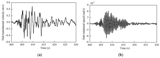
Figure 9.
Nacelle oscillation velocity when the input ground motion is seismic record 3; (a) translational velocity in x-axis, (b) angular velocity about y-axis.
The oscillation velocity of the blade in the x-axis is shown in Figure 10. From Figure 10a, the relative velocity amplitude of the blade tip was 4 m/s. According to Figure 10b, the absolute velocity amplitude of the blade tip was 6 m/s, which was larger than that excited by wind only. For the wind turbine at operational state, the increment of oscillation velocity of the blade caused by the earthquake can be computed by based on Equation (10). The oscillation velocity increment of the blade tip is shown in the Figure 10c and its amplitude was 4.6 m/s, which was even larger than the velocity amplitude induced by wind. The oscillation velocity amplitudes of the blade are compared in Figure 10d, where VWx represents the velocity amplitude of the blade excited by wind and ΔV represents the amplitude of blade velocity increment. The amplitude of blade velocity increment in the FA direction was non-monotonic, which was evidence that higher modes of blades are stimulated by seismic record 3. Moreover, the distribution of the transport velocity amplitude of the blade was in conflict with the assumption in the aerodynamic damping theory of wind turbine towers.
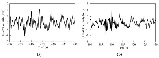
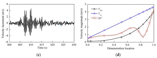
Figure 10.
Oscillation velocity of the blade along the x-axis when the input ground motion is seismic record 3; (a) relative velocity of blade tip, (b) absolute velocity of blade tip, (c) velocity increment of blade tip, (d) velocity amplitude along the blade.
Next, the oscillation velocity of the nacelle is shown in Figure 11, where the input ground motion was seismic record 4. According to Figure 11a, the translational velocity amplitude of the nacelle along the x-axis was 1.5 m/s, which was 10 times larger than that induced by the wind only. From Figure 11b, the angular velocity amplitude of the nacelle about the y-axis was 0.03 rad/s which was also 10 times larger than that induced by the wind only. The vibration velocity of the blade along the x-axis is shown in Figure 12. From Figure 12a, the relative velocity amplitude of the blade tip was 5m/s, which was larger than that caused by the wind. According Figure 12b, the absolute velocity amplitude of the blade tip was 5.9 m/s. The increment of oscillation velocity of the blade tip is shown in Figure 12c and the amplitude was 4.5 m/s. According to Figure 12d, the amplitude of the blade velocity increment along the x-axis increased monotonously from the root to the tip, and it was larger than the blade velocity induced by the wind. Similar to the former example, the transport velocity of the blade induced by the deformation of the support structure was in conflict with the assumption in the aerodynamic damping theory of wind turbine towers.
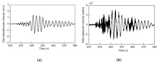
Figure 11.
Nacelle oscillation velocity when the input ground motion is seismic record 4; (a) translational velocity in x-axis, (b) angular velocity in y-axis.
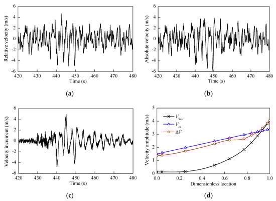
Figure 12.
Oscillation velocity of blade along the x-axis when the input ground motion is seismic record 4; (a) relative velocity of blade tip, (b) absolute velocity of blade tip, (c) velocity increment of blade tip, (d) velocity amplitude along the blade.
Considering the randomness of wind, five wind samples were generated by using the TurbSim code with different random seeds and then combined with all the seismic records in Table 3. To evaluate the influence of earthquakes on the vibration of the blade, the velocity increment factor ξ is defined as.
where j represents the index of wind sample; is the amplitude of blade velocity increment along the x-axis caused by earthquakes when the wind field is sample j; represents the amplitude of blade velocity about the x-axis induced by the wind sample j, and m = 5 denotes the sample size of the wind field.
Figure 13a,b represent the velocity increment factor for the middle and tip of the blade, respectively. The velocity increment at the middle section of the blade was even larger than the oscillation velocity induced by the wind for almost all the earthquake records, and the blade-tip velocity increment factor was larger than 50% for most earthquakes. Therefore, the oscillation velocity of the blade for the wind turbine at the operational state induced by some earthquakes did not meet the requirement in Equation (11), which is the base of the uncoupled method.
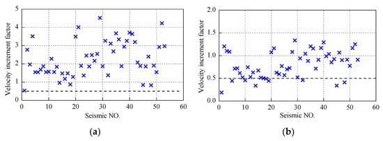
Figure 13.
Velocity increment factor of the blade at different locations; (a) middle of blade, (b) tip of blade.
3.2. Aerodynamic Loadings on the Rotor
For the wind turbine at the operational state, the oscillation velocity of blades in the FA direction is significantly changed by earthquakes, which will directly influence the aerodynamic loadings on the rotor. To assess this influence, the thrust variation is defined as:
where and are the aerodynamic thrust on the rotor excited by wind only and combined wind–earthquake load. When the earthquake was seismic record 3, the thrust increment on the rotor of wind turbines is shown in Figure 14a, and the amplitude was 37 kN. When the earthquake was seismic record 4, the thrust increment is shown in Figure 14b, and the amplitude was 270 kN.
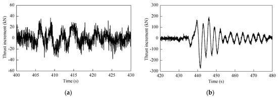
Figure 14.
Thrust variation on the rotor induced by (a) Seismic record 3 and (b) Seismic record 4.
For the earthquakes in Table 3, the thrust variation factor of the wind turbine at the operational state is defined as:
where j, and m have the same meaning and value as those of Equation (14); is the amplitude of thrust variation caused by earthquakes when the wind field is sample j; represents the amplitude of thrust induced by wind sample j.
The thrust variation factor shown in Figure 15a was larger than 0.15 for more than half of the earthquakes, and its maximum was 0.54. The relationship of thrust variation factor with respect to the amplitude of blade root velocity is examined in Figure 15b which indicates that the effect of earthquakes on the thrust increases with the amplitude of blade-root velocity. The aerodynamic loadings on the rotor were significantly changed by earthquakes. Consequently, the interaction of wind and earthquake loads must be considered in the coupled and uncoupled analysis. For the uncoupled model, the thrust variation induced by the earthquake was replaced by the equivalent aerodynamic damping.
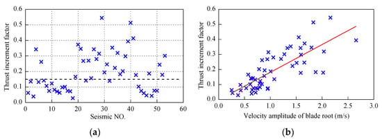
Figure 15.
Factor of thrust variation caused by different earthquakes; (a) thrust variation factor, (b) relation between thrust variation factor and velocity amplitude of blade root.
4. Comparisons of the Coupled and Uncoupled Methods
The analysis results of the coupled and uncoupled methods were compared to evaluate the accuracy of the uncoupled analysis method predicting the seismic response of wind turbines at the operational state. First, the response time-history of the two methods was compared for typical seismic records; next, the response amplitudes using the two methods were compared for different mean wind speed at hub height. Both of the two methods were implemented in the time domain by using the FAST code, where the damping ratios of blade and support structure modes were set as 0.4775% and 1% respectively.
4.1. Response Time History
The equivalent aerodynamic damping ratio for the uncoupled method is set to 4%, referring to the literature [31,32,33], and the wind field is the same as that of Section 3.1. For the first example, the input ground motion was the seismic record 3, and the responses were compared in Figure 16. The differences between the two methods were significant for tower-top acceleration and tower-base shear force and bending moment. Their amplitudes are listed in Table 4 where the tower-base bending-moment amplitudes were 120 MN·m and 90 MN·m for the coupled and uncoupled models, respectively. On the whole, the uncoupled model underestimates the amplitudes of the tower-top motion and the tower-base internal forces in this example.
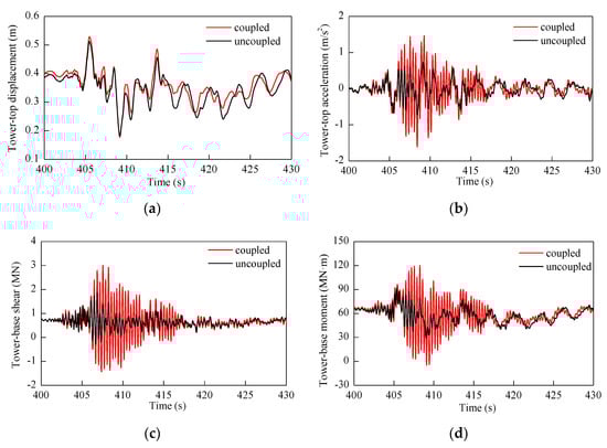
Figure 16.
Seismic response of wind turbine using coupled and uncoupled methods as the earthquake is seismic record 3; (a) tower-top displacement, (b) tower-top acceleration, (c) tower-base shear force, (d) tower-base bending moment.
Table 4.
Response amplitude of the wind turbine as the earthquake is seismic record 3.
Next, the input ground motion is changed to seismic record 4 in Table 3, and the responses of the wind turbine are shown in Figure 17. The response amplitudes are listed in Table 5 where the response amplitudes for the coupled method were less than those for the uncoupled method. Therefore, the uncoupled method overestimates the tower-top motion and the tower-base internal forces in this example.
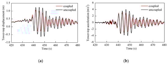
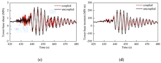
Figure 17.
Seismic response of wind turbine using coupled and uncoupled methods as the earthquake is seismic record 4; (a) tower-top displacement, (b) tower-top acceleration, (c) tower-base shear force, (d) tower-base bending moment.
Table 5.
Response amplitude of the wind turbine as the earthquake is seismic record 4.
Figure 18 compares the response amplitudes of the tower using the coupled and uncoupled methods, where E3 and E4 denote the responses induced by seismic records 3 and 4, respectively. It was observed that the differences between them were significant besides the two sections discussed above. Therefore, there was remarkable discrepancy between the results of these two methods for seismic records 3 and 4. Moreover, when the equivalent aerodynamic damping ratio was 4%, the uncoupled model respectively underestimated and overestimated the seismic response of the wind turbine in the two examples, which indicates the conflict tendency for optimizing the aerodynamic damping ratio to improve the accuracy of the uncoupled method.
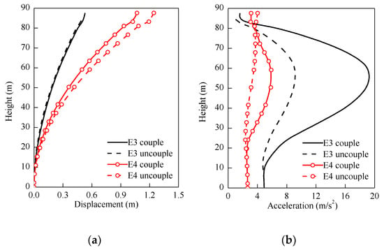
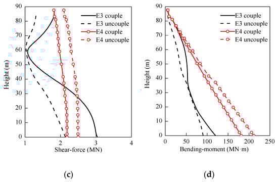
Figure 18.
Seismic response amplitude of the tower for seismic records 3 and 4; (a) relative displacement, (b) absolute acceleration, (c) shear force, (d) bending moment.
4.2. Response Amplitude
In order to evaluate the accuracy of the uncoupled method further, all the seismic records in Table 3 were taken as input ground motions and the simulation results using the two methods were compared. The displacement error ζd, acceleration error ζa, shear-force error ζF, and bending-moment error ζd are defined as:
where d and a are the tower-top displacement and acceleration amplitudes from the coupled model, while and are the corresponding quantities from the uncoupled model; F and M are the tower-base shear-force and bending-moment amplitudes from the coupled model, while and are the corresponding quantities for the uncoupled model. Therefore, if the error is larger than 0, the uncoupled model overestimates the seismic response of wind turbines. Conversely, the uncoupled model underestimates the seismic response. According to Chinese seismic standard [52], it is accepted that the uncoupled method has sufficient accuracy if the errors between the coupled and uncoupled methods are within the range of ±0.15, which is filled with grey in the following figures. Table 6 lists the mean wind speed at the hub and its sample size in the wind–earthquake load combinations for this section.
Table 6.
Parameters of wind field.
When the mean wind speed was 11.4 m/s and the equivalent aerodynamic damping ratio was 4%, the errors between the coupled and uncoupled analysis were calculated and are shown in Figure 19. For some earthquakes, such as seismic records 31–36 in Table 3, the relative errors of the four response quantities were within the range of ±0.15. However, the relative errors were beyond the range of ±0.15 significantly for other earthquakes, which indicated this uncoupled method was not universal to predict the seismic response of wind turbines. The prominent conflict was that the remarkable underestimation and overestimation of the seismic responses emerged simultaneously for different earthquakes, which cannot be solved by just optimizing the equivalent aerodynamic damping ratios.
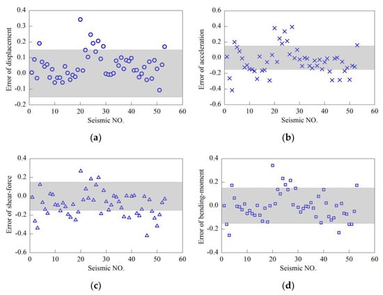
Figure 19.
Relative error between coupled and uncoupled analysis as aerodynamic damping ratio is 4% and mean wind speed at hub height equals 11.4 m/s; (a) tower-top displacement, (b) tower-top acceleration, (c) tower-base shear force, (d) tower-base bending moment.
As shown in Figure 20, all the errors were less than 0.15 when the aerodynamic damping was increased to 7%. Compared with Figure 19, the overestimation of seismic responses was eliminated by increasing the aerodynamic damping, but some errors were much less than −0.15. The error of tower-top acceleration for seismic record 3 was −0.52, while it was −0.42 as the aerodynamic damping ratio was 4%. Consequently, the uncoupled model with a 7% aerodynamic damping was also not suitable to predict the seismic response of wind turbines as it indicated sufficient accuracy only for some earthquakes, e.g., seismic records 22–26, without universality.
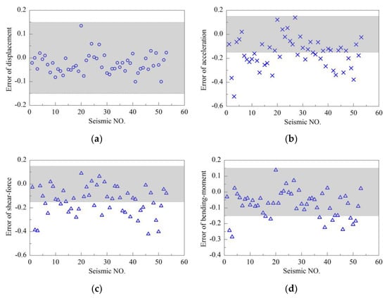
Figure 20.
Relative error between coupled and uncoupled analysis as aerodynamic damping ratio is 7% and mean wind speed at hub height equals 11.4 m/s; (a) tower-top displacement, (b) tower-top acceleration, (c) tower-base shear force, (d) tower-base bending moment.
Figure 21 shows the relative errors between the coupled and uncoupled analysis, where the legend is the ID of the seismic event listed in Table 3. The relative errors decreased monotonously, and they were less than 0 for all the earthquakes when the equivalent aerodynamic damping ratio was 10%. For seismic record 3, the errors were less than 0 as the aerodynamic damping ratio was 1%, and the errors of acceleration, shear force, and bending moment were less than −0.15 once the aerodynamic damping ratio increased to 2%. However, the errors of all response quantities for seismic record 20 were larger than 0.4 while the aerodynamic damping ratio was 2%, and it should reach 7% to reduce the errors to 0.15. Therefore, the uncoupled model was not sufficient to accurately predict the seismic response of wind turbines when the mean wind speed at the hub height was 11.4 m/s.
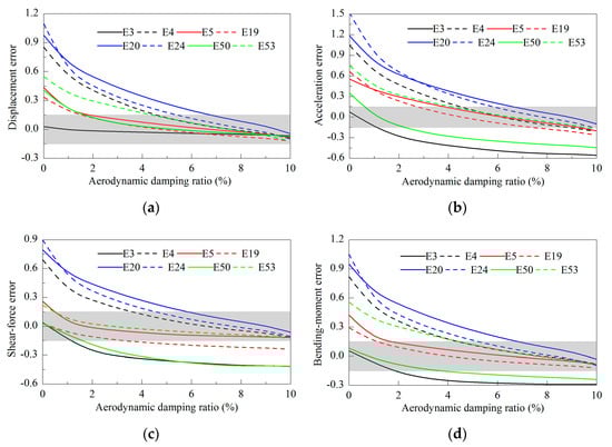
Figure 21.
Response error between coupled and uncoupled analysis for variable aerodynamic damping ratios as the mean wind speed at hub height is 11.4 m/s; (a) tower-top displacement, (b) tower-top acceleration, (c) tower-base shear force, (d) tower-base bending moment.
When the average wind speed of hub-height was set to 5 m/s and the aerodynamic damping was increased to 3%, Figure 22 shows that the errors between the two models were less than 0.15. The errors for some earthquakes may be significantly less than −0.15, where the errors of tower-base shear force for seismic record 46 were the most remarkable and the minimum was −0.42. The errors between the coupled and uncoupled methods for different aerodynamic damping ratios were compared in Figure 23, where the overestimation of seismic responses was less than that illustrated in Figure 21 on the whole. Taking the seismic record 20, for example, when the aerodynamic damping was 4%, all the errors were nearly 0 as the average wind speed was 5 m/s; however, the errors were larger than 0.4 as the mean wind speed was 11.4 m/s. Consequently, the errors between the two methods were associated with the mean wind speed of hub height. When the mean wind speed was 5 m/s, a consistent aerodynamic damping ratio did not exist for the uncoupled model to accurately predict the seismic response of wind turbines.
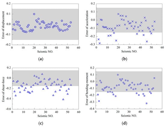
Figure 22.
Relative error between coupled and uncoupled analysis as aerodynamic damping ratio is 3% and mean wind speed at hub height equals 5 m/s; (a) tower-top displacement, (b) tower-top acceleration, (c) tower-base shear force, (d) tower-base bending moment.
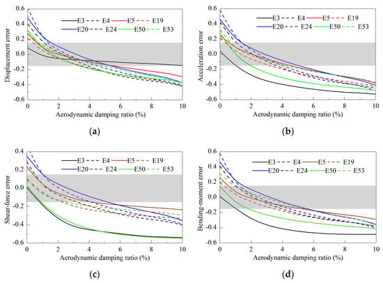
Figure 23.
Response error between coupled and uncoupled analysis for variable aerodynamic damping ratios as mean wind speed at hub height is 5 m/s; (a) tower-top displacement, (b) tower-top acceleration, (c) tower-base shear force, (d) tower-base bending moment.
When the average wind speed of hub height was set to 18 m/s and the aerodynamic damping was 7%, Figure 24 shows that the relative errors between the coupled and uncoupled methods were not larger than 0.15. The errors for some earthquakes may be substantially less than −0.15, where the error of tower-base shear force for seismic record 46 was the most prominent and the minimum was −0.51. The errors between the coupled and uncoupled models for different aerodynamic damping ratios were compared in Figure 25. For a specified earthquake and response quantity, there was an equivalent aerodynamic damping ratio to maintain the high accuracy of the uncoupled model. However, for all the earthquakes in Table 3, a consistent aerodynamic damping ratio could not be determined to maintain the accuracy of the uncoupled model.
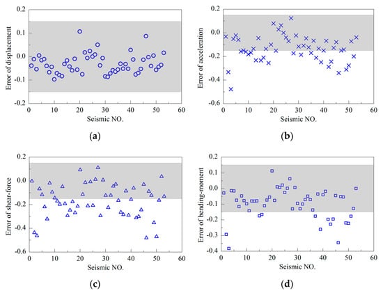
Figure 24.
Relative error between coupled and uncoupled analysis as aerodynamic damping ratio is 7% and mean wind speed at hub height equals 18 m/s; (a) tower-top displacement, (b) tower-top acceleration, (c) tower-base shear force, (d) tower-base bending moment.
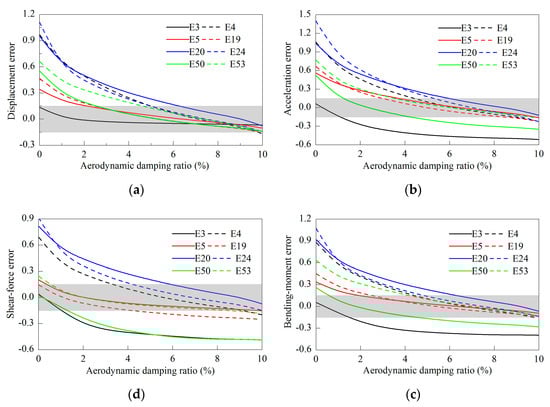
Figure 25.
Response error between coupled and uncoupled analysis for variable aerodynamic damping as the mean wind speed at hub height is 18 m/s; (a) tower-top displacement, (b) tower-top acceleration, (c) tower-base shear force, (d) tower-base bending moment.
From Figure 20a, Figure 22a and Figure 24a, the errors of tower-top displacement were within the range of ±15% when the mean wind speed was 11.4 m/s, 5 m/s and 18 m/s. Therefore, just investigating the tower-top displacement was not sufficient to evaluate the uncoupled method. The aerodynamic damping ratio corresponding to the uncoupled model of Figure 20a, Figure 22a and Figure 24a was 7%, 3% and 7%, respectively. This was consistent with the conclusion that the aerodynamic ratio was associated with the mean wind speed. Consequently, a consistent aerodynamic damping ratio cannot be determined for the uncoupled method with different mean wind speeds.
The comparisons between the coupled and uncoupled methods indicate that this uncoupled method is not universal to analyze the seismic response of wind turbines. For the uncoupled method, the thrust variation caused by the ground motion is replaced by the equivalent aerodynamic damping ratio. Nevertheless, the distribution of the transport velocity of the blade in the FA direction excited by wind and earthquake is inconsistent with the assumptions in the existing aerodynamic damping models of wind turbine. Moreover, the existing aerodynamic damping model was only established for the first tower mode. As a result, the update of the aerodynamic damping model for wind turbines may be a feasible way to improve the accuracy of the uncoupled method.
5. Conclusions
The accuracy of the uncoupled method predicting the seismic response of wind turbines was investigated in this study. Firstly, the vibration of blades and aerodynamic loading on the rotor were analyzed to evaluate the assumptions in the uncoupled method. Subsequently, the simulation results of coupled and uncoupled models were compared to assess the accuracy of the uncoupled method. Based on the results, some conclusions are summarized in the following points.
(1) The oscillation velocity of the blade along the FA direction of wind turbines may be greatly influenced by the ground motions. The angular velocity of the nacelle induced by wind and earthquake load may be significantly larger than that induced by wind only, which illustrates that the transport velocity of the blade does not meet the assumption of aerodynamic damping models for wind turbine towers.
(2) The resultant forces of the aerodynamic loaings on the rotor may be significantly impacted by the ground motions selected in the present study, such that the interaction of wind and earthquake load is substantial. The influence of ground motions should be taken into account when computing the aerodynamic loadings on the rotor of wind turbines excited by the wind and earthquake combination.
(3) The errors between the coupled and uncoupled methods are related to both the mean wind speed at the hub height and input ground motions. The consistent aerodynamic damping ratios cannot be determined to maintain the accuracy of the uncoupled method for different wind speed and earthquakes. Therefore, this uncoupled method cannot be utilized to analyze the seismic response of wind turbines at its current state.
It should be noted that an aerodynamic damping model consistent with the vibration characteristic of the blade induced by an earthquake should be established to improve the uncoupled analysis method. This aerodynamic damping model should include the modal aerodynamic damping of higher modes of wind turbines and contribution of the rotational degree of freedom of the tower top. The examples in Section 4.1 show that the uncoupled method has different performance for ground motions with different spectral characteristics. However, the numerical simulation is carried out in the time domain due to the nonlinearity of the coupled system. Therefore, the interaction between wind and earthquake should be also discussed in the frequency domain.
Author Contributions
Conceptualization, R.X., P.W. and X.D.; data curation, R.X., P.W.; formal analysis, R.X. and P.W.; investigation, R.X.; methodology, R.X., P.W. and X.D.; resources, R.X.; software, R.X., P.W. and X.D.; supervision, X.D.; visualization, R.X. and P.W.; writing—original draft, R.X. and P.W.; writing—review & editing, C.X. and J.J. All authors have read and agreed to the published version of the manuscript.
Funding
This research was funded by the National Natural Science Foundation of China, grant number 51808061, 51722801 and 51678014. The APC was funded by the National Natural Science Foundation of China, grant number 51808061.
Conflicts of Interest
The author declare no conflict of interest.
References
- Manwell, J.F.; Mcgowan, J.G.; Rogers, A.L. Wind Energy Explained: Theory, Design and Application; Wiley: Chichester, UK, 2010. [Google Scholar]
- Global Wind Energy Council (GWEC). Global Wind Report: Annual Market Update 2019. Available online: https://gwec.net/wp-content/uploads/2020/04/GWEC-Global-Wind-Report-2019.pdf (accessed on 20 May 2020).
- Katsanos, E.I.; Thöns, S.; Georgakis, C.Τ. Wind turbines and seismic hazard: A state-of-the-art review. Wind Energy 2016, 19, 2113–2133. [Google Scholar] [CrossRef]
- International Electrotechnical Commission (IEC). Wind Turbine-Part 1: Design Requirements, 3rd ed.; IEC 61400-1: Geneva, Switzerland, 2005. [Google Scholar]
- Germanischer Lloyd (GL). Guideline for the Certification of Wind Turbines; GL Renewables Certification: Hamburg, Germany, 2005. [Google Scholar]
- Witcher, D. Seismic analysis of wind turbines in the time domain. Wind Energy 2005, 8, 81–91. [Google Scholar] [CrossRef]
- Prowell, I.; Elgamal, A.; Uang, C.; Jonkman, J. Estimation of seismic load demand for a wind turbine in the time domain. In Proceedings of the European Wind Energy Conference (EWEC), Warsaw, Poland, 20–23 April 2010. [Google Scholar]
- Prowell, I.; Elgamal, A.; Uang, C.M.; Enrique, L.J.; Romanowitz, H.; Duggan, E. Shake table testing and numerical simulation of a utility-scale wind turbine including operational effects. Wind Energy 2014, 17, 997–1016. [Google Scholar] [CrossRef]
- Liu, Z.; Yang, Y.; Li, C.; Zou, J. Analysis of the Seismic Time-frequency Characteristics of the Derrick of a Wind Turbine Under a Soil-foundation-Structure Coupled Action. J. Eng. Therm. Energy Power 2018, 33, 129–136. (In Chinese) [Google Scholar]
- Zou, J.; Yang, Y.; Li, C.; Liu, Z.; Yuan, Q. Nonlinear characteristics of wind turbine tower vibration under turbulent wind and earthquake. J. Vib. Shock 2019, 38, 57–64. (In Chinese) [Google Scholar]
- Asareh, M.A.; Schonberg, W.; Volz, J. Effects of seismic and aerodynamic load interaction on structural dynamic response of multi-megawatt utility scale horizontal axis wind turbines. Renew. Energy 2016, 86, 49–58. [Google Scholar] [CrossRef]
- Yuan, C.; Chen, J.; Li, J.; Xu, Q. Fragility analysis of large-scale wind turbines under the combination of seismic and aerodynamic loads. Renew. Energy 2017, 113, 1122–1134. [Google Scholar] [CrossRef]
- Yang, Y.; Ye, K.; Li, C.; Michailides, C.; Zhang, W. Dynamic behavior of wind turbines influenced by aerodynamic damping and earthquake intensity. Wind Energy 2018, 21, 1–17. [Google Scholar] [CrossRef]
- Hänler, M.; Ritschel, U.; Warnke, I. Systematic modelling of wind turbine dynamics and earthquake loads on wind turbines. In Proceedings of the European Wind Energy Conference and Exhibition, Athens, Greece, 27 February–2 March 2006. [Google Scholar]
- He, Y.; Wang, L.; Du, J.; Jin, X. Vibration simulation analysis of wind turbine under seismic load. Acta Energ. Sol. Sin. 2012, 33, 179–184. (In Chinese) [Google Scholar]
- Jin, X.; Liu, H.; Ju, W. Wind turbine seismic load analysis based on numerical calculation. Slov. J. Mech. Eng. 2014, 60, 638–648. [Google Scholar] [CrossRef]
- Peng, C. Seismic dynamic response analysis of wind turbine. Acta Energ. Sol. Sin. 2016, 37, 3189–3194. (In Chinese) [Google Scholar]
- Wang, W.; Gao, Z.; Li, X.; Moan, T. Model test and numerical analysis of a multi-pile offshore wind turbine under seismic, wind, wave, and current loads. J. Offshore Mech. Arct. Eng. 2017, 139, 031901. [Google Scholar] [CrossRef]
- Bazeos, N.; Hatzigeorgiou, G.D.; Hondros, I.D.; Karamaneas, H.; Karabalis, D.L.; Beskos, D.E. Static, seismic and stability analyses of a prototype wind turbine steel tower. Eng. Struct. 2002, 24, 1015–1025. [Google Scholar] [CrossRef]
- Lavassas, I.; Nikolaidis, G.; Zervas, P.; Efthimiou, E.; Doudoumis, I.N.; Baniotopoulos, C.C. Analysis and design of the prototype of a steel 1-MW wind turbine tower. Eng. Struct. 2003, 25, 1097–1106. [Google Scholar] [CrossRef]
- Kiyomiya, O.; Rikiji, T.; van Gelder, P.H. Dynamic response analysis of onshore wind energy power units during earthquakes and wind. In Proceedings of the Twelfth International Offshore and Polar Engineering Conference, International Society of Offshore and Polar Engineers, Kitakyushu, Japan, 26–31 May 2002. [Google Scholar]
- He, G.; Li, J. Seismic analysis of wind turbine system including soil-structure interaction. In Proceedings of the 14th World Conference on Earthquake Engineering, Beijing, China, 12–17 October 2008. [Google Scholar]
- Martinez-Vazquez, P.; Gkantou, M.; Baniotopoulos, C. Strength demands of tall wind turbines subject to earthquakes and wind load. Procedia Eng. 2017, 199, 3212–3217. [Google Scholar] [CrossRef]
- Zhao, X.; Maißer, P. Seismic response analysis of wind turbine towers including soil structure interaction. Proc. Inst. Mech. Eng. K J. Multi Body Dyn. 2006, 220, 53–61. [Google Scholar] [CrossRef]
- Hansen, M.O.L.; Sørensen, J.N.; Voutsinas, S.; Sørensen, N.; Madsen, H.A. State of the art in wind turbine aerodynamics and aeroelasticity. Prog. Aeosp. Sci. 2006, 42, 285–330. [Google Scholar] [CrossRef]
- Ritschel, U.; Warnke, I.; Kirchner, J.; Meussen, B. Wind turbines and earthquakes. In Proceedings of the 2nd World Wind Energy Conference, Cape Town, South Africa, 23–26 November 2003. [Google Scholar]
- Ishihara, T.; Sarwar, M.W. Numerical and theoretical study on seismic response of wind turbines. In Proceedings of the European Wind Energy Conference and Exhibition, Brussels, Belgium, 31 March–3 April 2008. [Google Scholar]
- Fan, J.; Li, Q.; Zhang, Y. Collapse analysis of wind turbine tower under the coupled effects of wind and near-field earthquake. Wind Energy 2019, 22, 407–419. [Google Scholar] [CrossRef]
- Smith, V.; Mahmoud, H. Multihazard assessment of wind turbine towers under simultaneous application of wind, operation, and seismic loads. J. Perform. Constr. Facil. 2016, 30, 04016043. [Google Scholar] [CrossRef]
- Asareh, M.A.; Schonberg, W.; Volz, J. Fragility analysis of a 5-MW NREL wind turbine considering aero-elastic and seismic interaction using finite element method. Finite Elem. Anal. Des. 2016, 120, 57–67. [Google Scholar] [CrossRef]
- Santangelo, F.; Failla, G.; Santini, A.; Arena, F. Time-domain uncoupled analyses for seismic assessment of land-based wind turbines. Eng. Struct. 2016, 123, 275–299. [Google Scholar] [CrossRef]
- Santangelo, F.; Failla, G.; Arena, F.; Ruzzo, C. On time-domain uncoupled analyses for offshore wind turbines under seismic loads. Bull. Earthq. Eng. 2018, 16, 1007–1040. [Google Scholar] [CrossRef]
- Failla, G.; Santangelo, F.; Foti, G.; Scali, F.; Arena, F. Response-spectrum uncoupled analyses for seismic assessment of offshore wind turbines. J. Mar. Sci. Eng. 2018, 6, 85. [Google Scholar] [CrossRef]
- Zuo, H.; Bi, K.; Hao, H. Dynamic analyses of operating offshore wind turbines including soil-structure interaction. Eng. Struct. 2018, 157, 42–62. [Google Scholar] [CrossRef]
- Zuo, H.; Bi, K.; Hao, H.; Li, C. Influence of earthquake ground motion modelling on the dynamic responses of offshore wind turbines. Soil Dyn. Earthq. Eng. 2019, 121, 151–167. [Google Scholar] [CrossRef]
- Mo, R.; Kang, H.; Li, M.; Zhao, X. Seismic fragility analysis of monopile offshore wind turbines under different operational conditions. Energies 2017, 10, 1037. [Google Scholar] [CrossRef]
- Ju, S.H.; Huang, Y.C. Analyses of offshore wind turbine structures with soil-structure interaction under earthquakes. Ocean Eng. 2019, 187, 106190. [Google Scholar] [CrossRef]
- Jonkman, J.; Butterfield, S.; Musial, W.; Scott, G. Definition of a 5-MW Reference Wind Turbine for Offshore System Development; Technical Report NREL/TP-500-38060; National Renewable Energy Lab: Golden, CO, USA, 2009.
- Jonkman, J.M.; Buhl, M.L., Jr. Fast User’s Guide-Updated August 2005; Technical Report NREL/TP-500-38230; National Renewable Energy Lab: Golden, CO, USA, 2005.
- Jonkman, B.J. TurbSim User’s Guide: Version 1.50; Technical Report NREL/TP-500-46198; National Renewable Energy Laboratory: Golden, CO, USA, 2009.
- Stamatopoulos, G.N. Response of a wind turbine subjected to near-fault excitation and comparison with the Greek aseismic code provisions. Soil Dyn. Earthq. Eng. 2013, 46, 77–84. [Google Scholar] [CrossRef]
- ATC. Quantifcation of Building Seismic Performance Factors; Report NO. FEMAP695; Applied Technology Council: Redwood City, CA, USA, 2009. [Google Scholar]
- Prowell, I.; Elgamal, A.; Jonkman, J. FAST Simulation of Wind Turbine Seismic Response; Technical Report NREL/CP-500-46225; National Renewable Energy Laboratory: Golden, CO, USA, 2010.
- Leger, P.; Ide, I.M.; Paultre, P. Multiple support seismic analysis of large structures. Comput. Struct. 1990, 36, 1153–1158. [Google Scholar] [CrossRef]
- Mardfekri, M. Multi-hazard reliability assessment of offshore wind turbines. Eng. Struct. 2013, 52, 478–487. [Google Scholar] [CrossRef]
- Burton, T.; Sharpe, D.; Jenkins, N.; Bossanyi, E. Wind Energy Handbook; Wiley: New York, NY, USA, 2011. [Google Scholar]
- Valamanesh, V.; Myers, A. Aerodynamic damping and seismic response of horizontal axis wind turbine towers. J. Struct. Eng. 2014, 140, 04014090. [Google Scholar] [CrossRef]
- Liu, X.; Lu, C.; Li, G.; Godbole, A.; Chen, Y. Effects of aerodynamic damping on the tower load of offshore horizontal axis wind turbines. Appl. Energy 2017, 204, 1101–1114. [Google Scholar] [CrossRef]
- Chao, C.; Philippe, D. Modelling damping sources in monopile-supported offshore wind turbines. Wind Energy 2018, 21, 1121–1140. [Google Scholar]
- Hibbeler, R.C. Engineering Mechanics: Dynamic, 10th ed.; Pearson Education: New York, NY, USA, 2003. [Google Scholar]
- Moriarty, P.J.; Hansen, A.C. AeroDyn Theory Manual; Technical Report NREL/EL-500-36881; National Renewable Energy Laboratory: Golden, CO, USA, 2005.
- Ministry of Housing and Urban-Rural Development of the People’s Republic of China. Code for Seismic Design of Buildings; China Architecture & Building Press: Beijing, China, 2010.
© 2020 by the authors. Licensee MDPI, Basel, Switzerland. This article is an open access article distributed under the terms and conditions of the Creative Commons Attribution (CC BY) license (http://creativecommons.org/licenses/by/4.0/).