Article

Effect of Loudspeakers on the In Situ Electric Field in a Driver Body Model Exposed to an Electric Vehicle Wireless Power Transfer System

1
College of Electronic Engineering, Chengdu University of Information Technology, Chengdu 610225, China
2
Computer Science and Engineering, Nagoya Institute of Technology, Nagoya 466-8555, Japan
*
Author to whom correspondence should be addressed.
Energies 2020, 13(14), 3635; https://doi.org/10.3390/en13143635
Submission received: 25 June 2020 / Revised: 8 July 2020 / Accepted: 10 July 2020 / Published: 15 July 2020
(This article belongs to the Collection Invited Papers on Electric Vehicles)

Abstract

:
This study computationally evaluates the effect of loudspeakers on the in situ electric field in a driver body model exposed to the magnetic field from a wireless power transfer (WPT) system in an electric vehicle (EV), one with a body made of carbon fiber reinforced plastic (CFRP) and the other made with aluminum. A quasi-static two-step approach was applied to compute the in situ electric field. The computational results showed that the magnetic field distribution generated by the WPT is significantly altered around the loudspeakers, and shows obvious discontinuity and local enhancement. The maximum spatial-average magnetic field strength in the driver’s body was increased by 11% in the CFRP vehicle. It was 2.25 times larger than the reference levels (RL) prescribed in the International Commission of Non-Ionizing Radiation Protection (ICNIRP) guidelines in 2010. In addition, we found that the in situ electric field computed by the line- and volume-averaging methods were stable if the top 0.1% voxels are excluded. The maximum value was well below the basic restriction (BR) of the ICNIRP guidelines. Nevertheless, the presence of the loudspeaker led to increments in the electric field strength in parts of the human body, suggesting the potential influence of permissible transmitting power in the WPT system. The maximum electric field strength in the thigh and buttock with the woofer, increased by 27% in the CFRP vehicle. The arm value was up to 3 times higher than that obtained without the tweeter in the aluminum vehicle. Moreover, this study found that the maximum electric field strength depended on the location of the loudspeaker with respect to the WPT system and the separation from the driver model. Therefore, the loudspeaker should be considered when evaluating the maximum in situ electric field strength in the vehicle body design stage.

1. Introduction

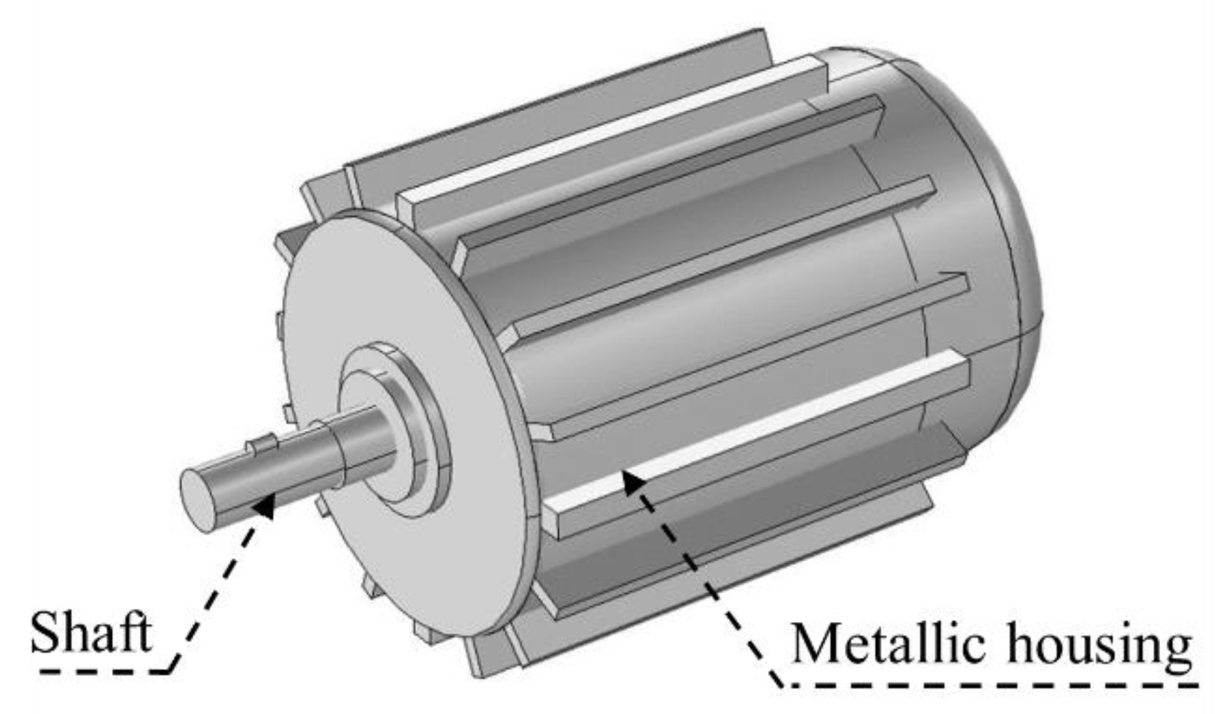
Recently, there has been increased interest in wireless power transfer (WPT) systems owing to their convenience in charging wireless devices such as mobile phones, household appliances, and electric vehicles (EVs) (e.g., [1]). Furthermore, EVs have attracted significant attention as an alternative for reducing the air pollution produced by diesel powered vehicles. Electric vehicles with a WPT system do not require power transmission wiring, hence, the possibility of electrical leakage from the plug under wet conditions is reduced [2]. However, electromagnetic field leakage from the WPT system, which is the main source of leakage in the EV, may pose potential health risks to humans. Another potential field source is the motor. However, the field leakage from the motor is very localized [3] and quite small [4] because the EV motor has a metallic housing (see Figure A1 in Appendix A) that is usually made of aluminum alloy and can effectively shield the electromagnetic field from the motor. In addition, EVs usually use a front- or rear-motor design. On the other hand, magnetic field leakage from the WPT system should not be ignored because the WPT system operates in an open environment and its transmitting power is on the order of several kilowatts or higher [5]. The induced in situ electric field might have adverse health effects on humans. Thus, it is crucial to assess human exposure to electromagnetic fields from EV WPT system.
The international exposure guidelines/standards, including the International Commission of Non-Ionizing Radiation Protection (ICNIRP) guidelines [6,7,8] and the standards set by the IEEE International Committee on Electromagnetic Safety (ICES) Technical Committee (TC-95) [9] were issued to protect humans from adverse health effects, electrostimulation (<100 kHz) and radiofrequency heating effects (>5 or 10 MHz). The International Electrotechnical Commission (IEC) also established a working group for computational assessment and its guidelines/standards prescribe a computational method for assessing the internal field. The limits for electrostimulation and heating effects are defined by the in situ (internal) electric field strength and specific absorption rate (SAR), respectively. To assess the compliance of WPT systems in EVs with these exposure standards, the measured maximum external field strength should be compared to the reference levels (RL) of the ICNIRP guidelines, which is the maximum permissible exposure strength in a free space. However, the RL is derived based on the assumption of a human body exposed to a uniform magnetic field in the open air, which is typically considered to be the worst-case exposure and results in conservativeness [8,9]. The magnetic field leaked from the WPT system is non-uniform. Therefore, the assessment defined by the spatial peak magnetic field strength may be conservative, as reported previously [10,11,12,13,14,15]. Limits for the in situ electric field- basic restriction (BR) for the ICNIRP and dosimetric reference levels (DRL) for the IEEE are needed. The IEC TC106 [16,17] introduces a coupling factor, which may compensate for the field distribution non-uniformity, although it is not generalized.
To date, no measurement has been performed because it is impossible to assess the induced electric field in the human body in a non-invasive manner. Therefore, numerical approaches to electromagnetic dosimetry assessment have been widely adopted [15,18,19,20,21,22,23], as even discussed in the product safety standard [16,17]. For example, Miwa et al. [15] evaluated the internal electric field induced by EV WPT systems with different types of vehicle body materials. Shimamoto et al. [18] studied the influence of the WPT coil structure on the internal electric field for different human models. They [19] also studied the influence of human posture outside the vehicle cabin. De Santis et al. [20] performed dosimetry analysis for a carbon fiber reinforced plastic (CFRP) vehicle. Shah and Yoo [21] evaluated the effects of implant metal on the SAR induced by the EV WPT system. Park [22] assessed electromagnetic dosimetry for different exposure scenarios. In [23], Cimala et al. evaluated a human body exposed to the magnetic field from the inductive power transfer systems in an electric or hybrid vehicle, including the finite conductivity of the vehicle body. However, these studies considered the effect of the vehicle body without considering the details of the interior structure. Ferrite materials (loudspeakers, electromotors, etc.) may affect the magnetic field distribution inside the vehicle. For example, the soft iron in loudspeakers has high permeability, and thus it can significantly affect the magnetic field distribution by guiding the magnetic flux [24,25]. Meanwhile, the loudspeakers, such as the woofer under the driver’s seat and the tweeter in the vehicle door are close to the driver’s body. Therefore, they modify the in situ electric field in the human body, which could have a potential influence on the EV design. However, the effect of such equipment inside the vehicle body has not yet been studied. Such investigation is clearly necessary for product development and to provide a conservative estimation of the effects of such interior equipment. Previously, the influence of accessories on the distribution of SAR due to mobile phone usage has been extensively studied [26,27,28].
This study investigates the effects of loudspeakers on the in situ electric field in a driver’s body exposed to EV WPT systems, where the vehicle body is made of CFRP or aluminum. The transmitted power and operating frequency of the WPT systems were 3.7 kW and 85 kHz, respectively. Different loudspeakers including the woofer under the seat and the tweeter in the vehicle door were considered. According to the magneto-quasi-static (MQS) approximation, the magnetic field was first determined using COMSOL Multiphysics 5.3a without including a driver model. Next, the in situ electric field in a driver’s body was computed using the scalar potential finite-difference (SPFD) method. This study compares the external magnetic field and the in situ electric field in a driver’s body when the vehicle is assembled with and without the loudspeakers. We also evaluated the difference in the effects of the loudspeakers calculated by two different post-processing methods for computing the average in situ electric field. Finally, the dependence of the maximum in situ electric field strength on the separation between the driver and the loudspeakers was also evaluated.

2. Numerical Model and Method

To perform the evaluation in a standardized and/or worst-case scenario, we first developed a vehicle model (including the loudspeaker and WPT system) based on a realistic exposure scenario. Note that in real life, expected exposure would be less than the values reported in this study. The loudspeakers (woofer under the driver seat and tweeter in the vehicle gate) evaluated in this study are close to the driver’s body. The WPT system follows the SAE J2954 and ISO 19363 standards. In addition, the post-processing of the magnetic field strength and in situ electric field were all strictly based on international safety guidelines/standards. Moreover, we evaluated the magnetic field and in situ electric field in four measurement positions as defined by the IEC TS 62764 standard, which helped us to compare our results with the safety standards.

2.1. Vehicle Model with WPT System

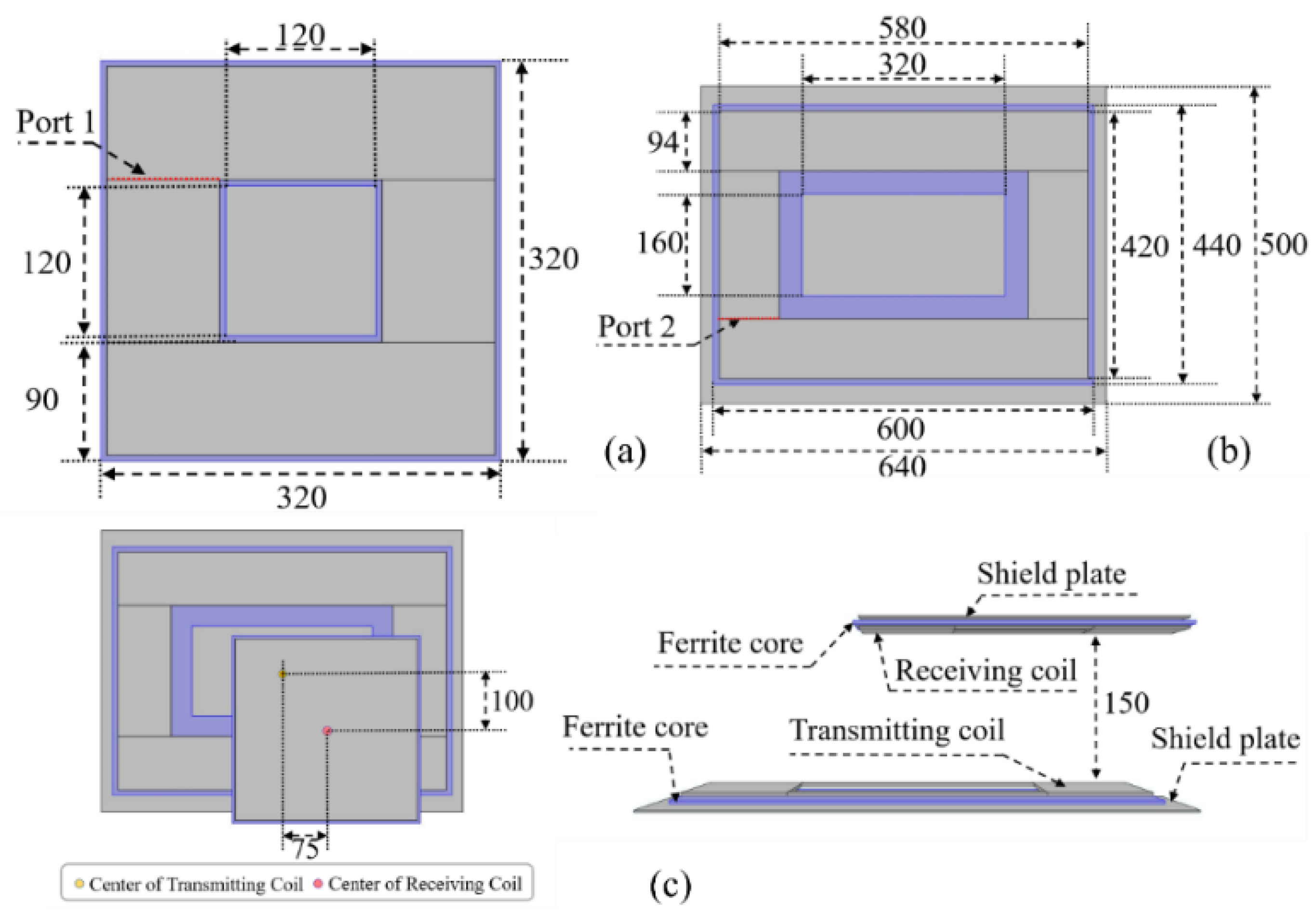
The WPT system was implemented in a simplified vehicle model (shown in Figure 1) based on the Toyota Motor Corporation Prius. We chose aluminum or CFRP as the body material. The relative permittivity, relative permeability, and conductivity of aluminum and CFRP are (1, 1, and 3.8 × 10⁷ S/m) and (1, 1, and 2.5 × 10⁵ S/m), respectively. The thickness of the vehicle body for aluminum and CFRP were 1 mm and 2 mm, respectively. The data in this study is not normalized. The source of the electromagnetic field is the EV WPT system, which is composed of a ferrite core, shield plate, and transmitting and receiving coils. Figure 2 shows the detailed structure of the WPT system according to SAE J2954 and ISO 19363 standards [29]. The thickness of the ferrite core and shield plate is 3 mm and 2 mm, respectively. The transmitting and receiving coils are installed below the central part of the vehicle chassis. The number of turns and thickness for the transmitting and receiving coils are 15 turns, 3 mm, and 20 turns, 2 mm, respectively. The transmission distance between the transmitting and receiving coils is 150 mm. Misaligned coils rather than the face to face type were used because the larger coil current at the misaligned position could cause a larger leaked magnetic field strength. The misalignment along the x and y directions are 75 mm and 100 mm, respectively [30]. In [30], the magnetic field strength is in agreement (within 20%) though the experimental vehicle body was simplified. To transfer 3.7 kW power at 85 kHz (SAE J2954 standards and ISO 19363 standards [29]), the current sources at the Port T and port R were 16 A and 17 A, respectively. The phase difference between Ports 1 and 2 was −90°. The fixed current for the transmitting and receiving coils can eliminate the interference of surrounding objects on the transmitting power and efficiency of the WPT system. Although the simultaneous exposure to multiple frequencies is also an important topic in numerical dosimetry, the strongest external electromagnetic field source in this study is from the WPT system operating at 85 kHz. Furthermore, it was assumed that the peak in situ electric field would appear in different places. Thus, based on the above reasons, the summation effect was not considered in this study.

2.2. Loudspeaker Configuration

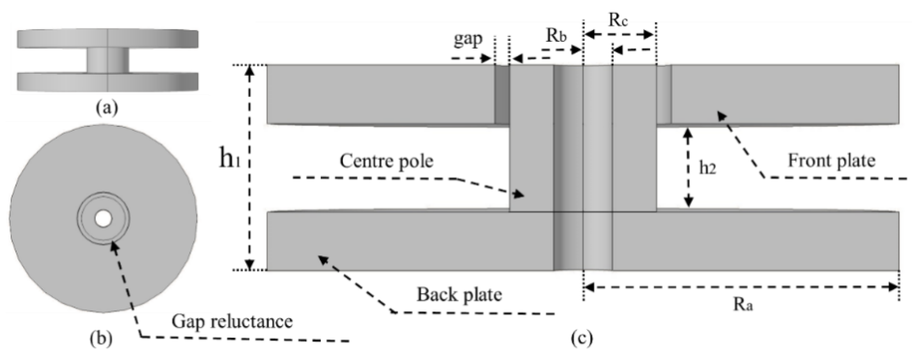
A simplified soft iron model is used to represent the woofer and tweeter, which have similar structures but different sizes [31]. As shown in Figure 3, the loudspeaker includes the front plate, central pole, and back plate, which are made of low-carbon steel. The detailed sizes for the woofer and tweeter are shown in Table 1.

2.3. Numerical Human Body Model

This study used an adult male model (TARO) developed by the National Institute of Information and Communications Technology. The TARO model includes 51 tissues and has a resolution of 2 mm × 2 mm × 2 mm. The dielectric properties of tissues and organs are modeled by the fourth-order Cole–Cole model of [32]. The TARO model was adjusted to have the driver sitting on the seat. The distance between the driver and the receiving coils was set at 150 mm, which represents a realistic vehicle environment. The whole body is divided into four parts as shown in Figure 4 according to the IEC TS 62764 [33], which defines the position of the measurement.

2.4. Computational Methods

The MQS approximation is applicable for computing the in situ electric field when the frequency is lower than 10 MHz [12,34]. Under the MQS approximation, the external electric field and magnetic field are decoupled. Meanwhile, the effects of a human body on the magnetic field distribution are marginal. Therefore, we first computed the external magnetic field and magnetic potential vector induced by the WPT system using the commercial software (COMSOL Multiphysics 5.3a) without including the human model in the vehicle (shown in Figure 1). Then the in situ electric field in the driver body was computed by the SPFD method, which substitutes the magnetic vector potential into an electromagnetic solver. The original TARO model has a spatial resolution of 2 mm, which is based on the MR images. In addition, according to the ICNIRP guidelines, the dose metric for BR compliance assessment is defined as the electric field vector average in a contiguous tissue volume of 2 mm × 2 mm × 2 mm. Therefore, cubical grids with a side length of 2 mm were used in this study. The total computational volume (shown in Figure 1) is 1262 mm × 508 mm × 1012 mm, which includes the driver model (1242 mm × 488 mm × 992 mm). The SPFD linear equation system was iteratively solved by the six-level multigrid method, which was developed by the Nagoya Institute of Technology. The rotation number per layer is (3, 8, 15, 25, 40, 60). The iteration does not stop until the relative residual is less than 10−6. The estimated error for the electric field was less than 0.5% [35].

2.5. Post-Processing of External Magnetic Field Strength

To adopt the 100 cm2 loop antenna in accordance with the IEC standard [17], we computed the peak spatial-average magnetic field strength, which is the averaged value of the vector summation of the x, y, and z components averaged over 100 cm2 in the computational region.

2.6. Post-Processing of In Situ Electric Field by Volume- and Line-Averaging Method

The ICNIRP guidelines define the dose metric for BR compliance assessment as the electric field strength averaged over a contiguous tissue volume of 2 mm × 2 mm × 2 mm. The 99th percentile value of the electric field is used as the dose metric for uniform electromagnetic exposure, which removes the highest 1% of internal electric field data from the entire evaluated volumes. This process contributes to the suppression of computational artifacts. However, this metric is known to underestimate the maximum internal electric field, especially for localized exposure scenarios [6,7,36]. Therefore, methods such as the 99.9th percentile value (the top 0.1% maximum field strength values for the entire body are eliminated) [15] or smoothing tissue conductivities [37] have been used by different groups.
From the IEEE standard, “the in situ electric field DRL applies to the rms electric field strength measured in the direction and location providing the maximum in situ electric field vector (vector magnitude) over a 5 mm linear distance.” However, the method for computing the line-averaging value is not presented in the IEEE standard. This is primarily because the ellipsoidal model rather than an anatomical model is used to determine the coupling between the magnetic field and tissue. Meanwhile, the IEEE standard does not use the percentile value because the underlying dosimetry is based on the closed-form solution of the uniform isotropic ellipsoidal model. This study computed the line-averaging in situ electric field by Equation (1) [38],
E L = { m a x ( 1 L 1 r l ( r ) E ( r ) )       p < p m a x     0   V / m                                     otherwise   ,
where E L is the maximum averaging value of a 5-mm line about different directions, which takes the target voxel r as the center voxel. L1 is the length of the segment within the same tissue. l ( r ) is the length of the segment intersected about the 5-mm line. The parameter p defined by Equation (2) represents the ratio between air and other tissues.
p = L L 1 L ,
This proposed line-averaging method could be applied to the voxels at the tissue boundaries. A detailed description can be found in [38].

3. Results and Discussion

3.1. Effects of Loudspeakers on the External Magnetic Field in the Vehicle

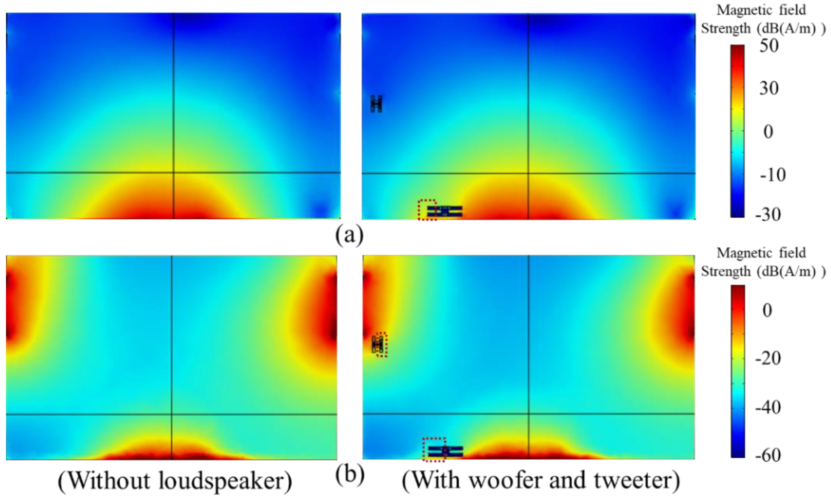
Firstly, this section compares the external magnetic field distribution in the vehicle with and without considering the glass windows in the vehicle gate (the relative permeability is 4.2 and conductivity is 1 × 10⁻¹⁴ S/m). The results are shown in the Figure 5. We found that the windows in the vehicle gate have less effect on the magnetic field distribution. This is because glass is a non-magnetic material and has low relative permeability and conductivity. Therefore, we did not consider the vehicle glass window in the following evaluations. Then, we evaluated the loudspeaker effects on the magnetic field distribution in the CFRP and the aluminum vehicle without the presence of the driver model. Figure 6a shows the leaked magnetic field from the WPT system entering the CFRP vehicle directly from the chassis. However, as shown in Figure 6b, the magnetic field in the aluminum vehicle is primarily leaked from the windows. The strength of the magnetic field in the CFRP vehicle is higher than that of the aluminum vehicle. Meanwhile, the WPT-generated magnetic field distribution is significantly altered around the woofer in the CFRP vehicle and around the tweeter in the aluminum vehicle where obvious discontinuity and local enhancement can be observed. This is caused by the high permeability of the woofer and tweeter, which results in the magnetic field concentration around them. In contrast, the influence of the tweeter in the CFRP vehicle and the woofer in the aluminum vehicle on the magnetic field can be ignored because the magnetic field around them is relatively weak.
Table 2 shows the peak spatial-average magnetic field strength in different driver body measurement positions, which were compared with the RL in the ICNIRP guidelines. We found that the woofer in the CFRP vehicle resulted in an increase of 11% in the peak spatial-average magnetic field strength in the thigh and buttocks. This is 2.25 times higher than the RL of the 2010 ICNIRP guidelines. The above results demonstrate that the loudspeaker (magnetic materials in the vehicle) might enhance the internal electric field and should be considered in the electromagnetic dosimetry for EV WPT systems.

3.2. Effects of the Loudspeaker on the Difference between Volume- and Line-Averaging Methods

In this section, we evaluate the loudspeaker effects on the difference between the volume-averaging and line-averaging methods in terms of relative difference dr, which is defined by Equation (3) [38].
d r = E V E L 1 2 ( E V + E L ) × 100 ,
where E V and E L are the maximum volume- and line-averaging of the in situ electric field strength, respectively. We compared the relative difference between these two averaging methods at different driver body positions when the vehicle is assembled with and without loudspeakers. The results are shown in Table 3 for the CFRP vehicle and Table 4 for the aluminum vehicle. The largest relative difference between the volume- and line-averaging were 27.6% (thigh and buttocks) and 42.9% (trunk) for the CFRP and aluminum vehicle, respectively. In comparison, the relative difference increased by 77% in the driver model shin for the CFRP vehicle, and decreased by 27% in the driver model trunk for the aluminum vehicle under the effects of the loudspeaker. However, the maximal relative difference is less than 5% if the highest top 0.1% electric fields are excluded.
In general, the averaging values computed by the line- and volume-averaging methods are stable for different driver model measurement positions for exposure to the WPT system magnetic field for EVs, excluding the top 0.1% voxels. For this reason, the following study mainly concentrated on the 99.9th percentile values from the volume-averaging method.

3.3. Loudspeaker Effects on the In Situ Induced Electric Field

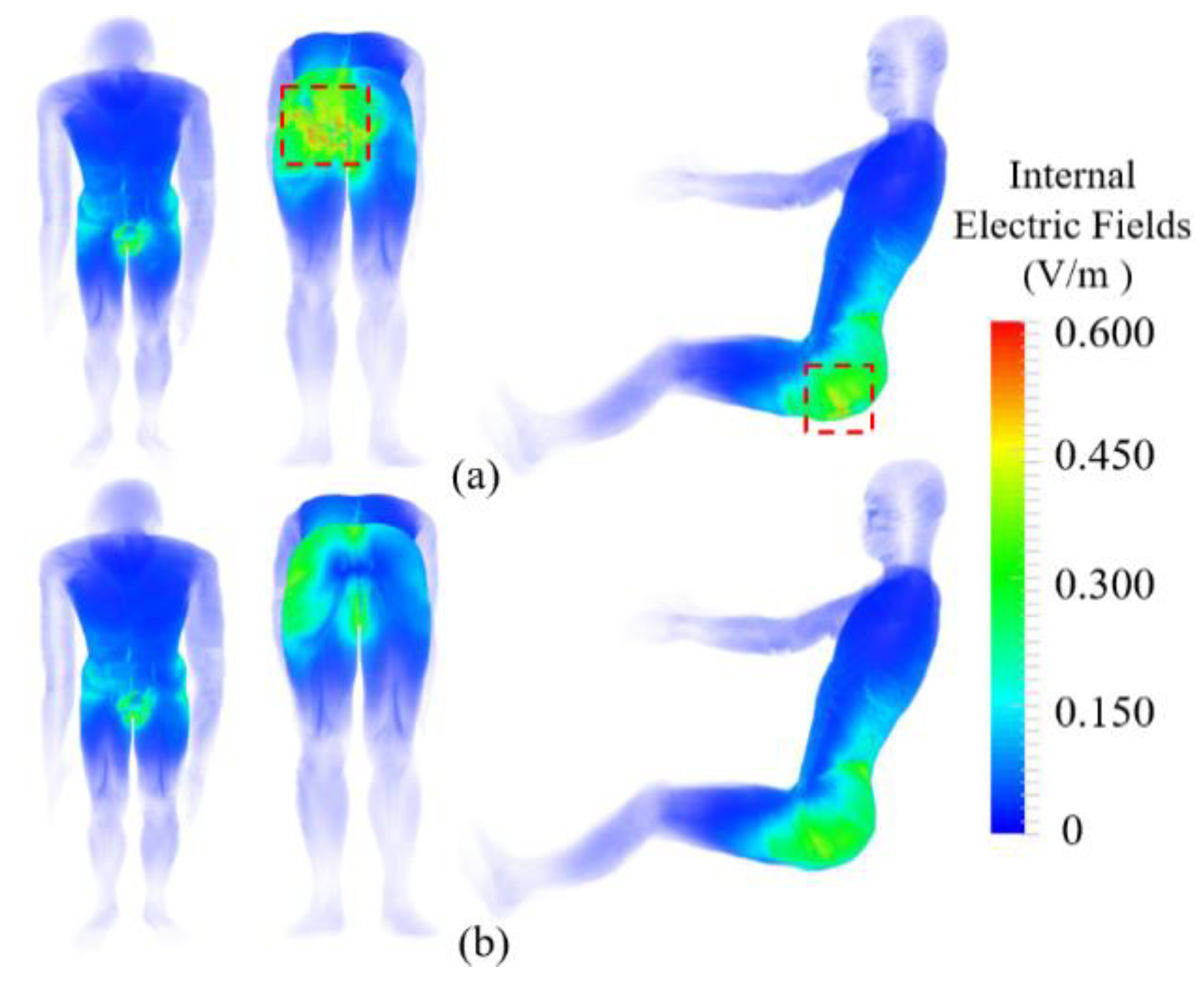
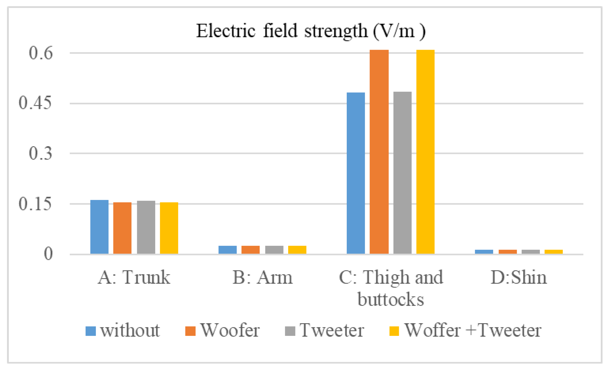
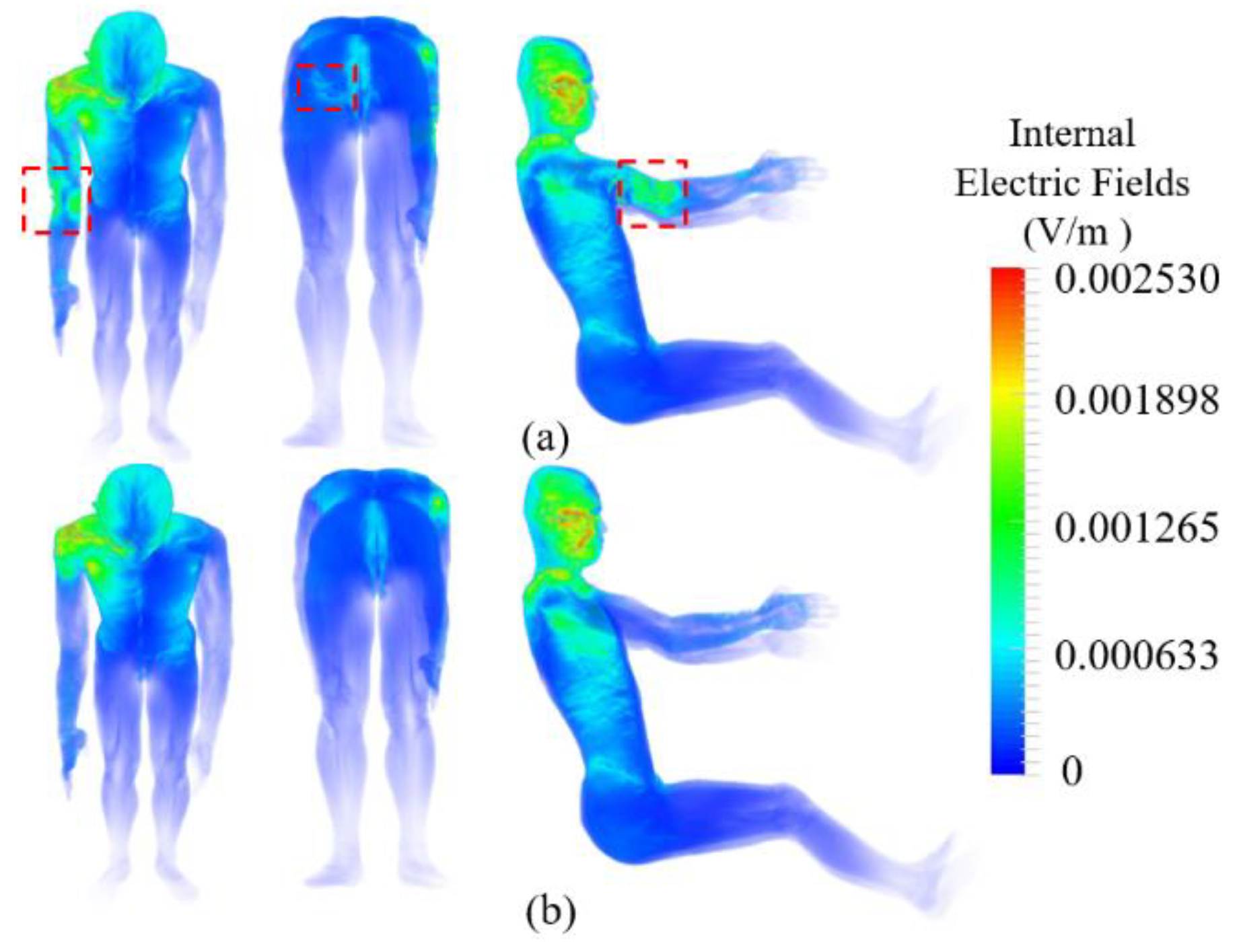
This section evaluates the loudspeaker effects on the in situ electric field when the driver’s body is exposed to the WPT system of CFRP and aluminum EVs. The electric field distribution and the maximum electric field strength were compared when the CFRP and aluminum vehicle were with and without the loudspeakers. For the CFRP vehicle, the electric field strength in the thigh and buttocks increased significantly, as can be seen in Figure 7. This is attributable to the increase in the external magnetic field around the woofer, which is close to the thigh and buttock. Figure 8 demonstrates that the woofer may cause an increase in the maximum electric field strength in the thigh and buttock. The spatial peak value is 0.6 V/m, which is an increase of 27% compared to the case without the woofer. For the aluminum vehicle, obvious increments appear on the right arm (shown in Figure 9), which is close to the tweeter. Figure 10 shows that the maximum electric field strength in the arm with the tweeter is approximately 3 times larger than that without it.
To conduct the compliance assessment against the exposure standards, we compared the maximum electric field with the BR (11.5 V/m) prescribed in the 2010 ICNIRP guidelines at 85 kHz. The in situ electric field is well below the BR in the ICNIRP guidelines. It is difficult to carry out a precise quantitative comparison between our computational results and those of other studies due to differences in the models, for example, in the EV (structure, materials etc.), WPT system (coil structure, location, power, etc.), and human body (dielectric properties, morphology, location, gesture, etc.). Nonetheless, similar findings were reported in [15,20]. For example, the results of [15] (wherein the EV and WPT system are identical to those shown in Figure 1) showed that the maximum averaged magnetic field was 1.1 times more than the RL in the ICNIRP guidelines. The maximum internal electric field was only 0.04 times that of the ICNIRP BR. The difference between our computational results and those in [15] is relatively small, which may be attributable to the use of a different model (human model with different location and gestures; loudspeaker close to the human body). In [20], the ICNIRP RL and BR are exceeded by 24.2 dB and 4.8 dB under the misaligned condition, respectively. Compared to the BR, the overexposure is primarily due to the high transmission power (7.7 kW) and extremely small separation between the driver’s feet and the WPT coils. However, overexposure was found only in a small part of the driver’s feet. In general, these results prove that the spatial-average magnetic field strength might be a conservative exposure metric for EV WPT systems. Additionally, the loudspeaker might change the permissible WPT transmitting power by affecting the coupling between the magnetic field and the human body [39]. Therefore, the loudspeaker effects should be considered in the design of EV systems.

3.4. Dependence of the Maximum Electric Field Strength on Separation between the Driver Model and Loudspeakers

To evaluate the dependence of the maximum induced electric field strength on the separation between the driver model and the loudspeakers, the woofer in the CFRP vehicle (shown in Figure 1) was moved along the x and y directions while the driver model was fixed. Table 5 and Table 6 show the variation in the maximum electric field strength at different measurement positions with the adjusted woofer in the CFRP vehicle. XS (Xw-Xd) and YS (Yw-Yd) are the coordinate difference values between the woofer and driver model along the x and y directions (shown in Figure 1b). These results show that the maximum electric field strength fluctuates with varying XS and YS. Those in the thigh and buttocks have the largest relative variation with ranges of 43.6% and 20.8%, respectively. This is because the magnetic field distribution in the thigh and buttocks is significantly altered by the nearby woofer, which guide the magnetic flux, and result in the concentration of the magnetic field around it. In addition, the peak value appears when the XS (in Table 5) and YS (in Table 6) are equal to −50 mm and −100 mm, rather than the minimum separation (XS = YS = 0). When the woofer is away from the WPT system (XS = 100 mm in Table 5, YS = 150 mm in Table 6), the maximum electric field strength is reduced to that without the woofer. This is due to the non-uniform magnetic field distribution in the EV (shown in Figure 6). The larger the separation between the woofer and WPT system, the weaker the magnetic field strength around the woofer. Table 7 shows the maximum electric field strength variation when the tweeter is adjusted along the z direction in the aluminum vehicle. ZS (Zt-Zd) represents the difference in the coordinates between the tweeter and the arm (shown in Figure 1a). As can be observed, the maximum electric field strength in the arm has the largest relative variation range, which goes up to 325%. In addition, the maximum electric field strength is predominantly affected by the separation between the tweeter and the arm. The peak value appears when the separation between the tweeter and arm is minimal (ZS = 0). When ZS is equal to 150 mm, the maximum electric field strength is reduced to that without the tweeter. The reason for this result is that the tweeter is close to the arm and the magnetic field is concentrated in the arm. In contrast, the nonuniformity of the magnetic field has a smaller effect on the peak value as the magnetic field gradient around the tweeter (shown in Figure 6b) is smaller than that around the woofer (shown in Figure 6a). In summary, the abovementioned results reveal that the maximum electric field strength is influenced not only by the separation between the driver model and the loudspeakers, but also the location of the loudspeaker with respect to the WPT system. The maximum electric field strength could be induced by moving the loudspeaker location.

4. Conclusions

The computational results of this study showed that loudspeakers have a significant influence on the magnetic field distribution in an electric vehicle. The peak spatial-average magnetic field strength in the driver’s body in the CFRP vehicle increased by 11%, and exceeded the RL recommended in the 2010 ICNIRP guidelines by 1.15 times. In addition, we found that the difference in the loudspeaker effect calculated by the volume- and line-averaging methods could be neglected if the top 0.1% voxels were excluded when evaluating the averaged in situ electric field. The maximum electric field strength in the driver’s body is not only influenced by the separation between the driver model and the loudspeakers, but also its location with respect to the WPT system. The loudspeaker can enhance the maximum electric field strength in localized parts of the driver’s body, which suggests the potential influence of permissible transmitting power in the WPT system. The largest relative increments were more than 200%, which appeared in the arm close to the tweeter in the aluminum vehicle. Although the maximum electric field strength was well below the BR in the 2010 ICNIRP guidelines, it was still within the same order of magnitude. Therefore, the loudspeaker effects should be considered in the design of EV systems, especially for highly and efficiently powered WPT systems.

Author Contributions

J.L. established the EV model with a WPT system and carried out the simulation. A.H. and J.L. analyzed the simulation results and wrote the paper. All authors have read and agreed to the published version of the manuscript.

Funding

Junqing Lan was supported by the China Scholarship Council (grant no. 201908515016).

Conflicts of Interest

The authors declare no conflict of interest.

Appendix A

Figure A1. Schematic representation of a typical motor model in electrical vehicles.
Energies 13 03635 g0a1

References

  1. Covic, G.A.; Boys, J.T. Inductive power transfer. Proc. IEEE 2013, 101, 1276–1289. [Google Scholar] [CrossRef]
  2. Yang, Y.; El Baghdadi, M.; Lan, Y.; Benomar, Y.; Van Mierlo, J.; Hegazy, O. Design methodology, modeling, and comparative study of wireless power transfer systems for electric vehicles. Energies 2018, 11, 1716. [Google Scholar] [CrossRef] [Green Version]
  3. Du, X.; Nie, X.; Jiao, M.; Chen, X.; Zhao, Y.; Zhao, X. Study on the Shaft EMI Noise of Electric Drive System in EV and HEV. In Proceedings of the Joint International Symposium on Electromagnetic Compatibility Sapporo and Asia-Pacific International Symposium on Electromagnetic Compatibility (EMC Sapporo/APEMC), Sapporo, Hokkaido, Japan, 3–7 June 2019; pp. 455–458. [Google Scholar]
  4. Pääkkönen, R.; Korpinen, L. Low Frequency Magnetic Fields inside Cars. Radiat. Prot. Dosim. 2020, 187, 268–271. [Google Scholar] [CrossRef] [PubMed]
  5. Ichikawa, S.; Mori, A.; Kawakubo, A. Development of short range wireless power transfer test system using magnetic resonance: (3) magnetic field characteristic of a kW-class system using solenoid coils. In Proceedings of the IEICE Communications Society Conference, Fukuoka, Japan, 17–20 September 2013. (In Japanese). [Google Scholar]
  6. International Commission on Non-Ionizing Radiation Protection. Guidelines for limiting exposure to time-varying electric and magnetic fields (1 Hz to 100 kHz). Health Phys. 2010, 99, 816–836. [Google Scholar]
  7. International Commission on Non-Ionizing Radiation Protection. Guidelines for limiting exposure to time-varying electric, magnetic, and electromagnetic fields (up to 300 GHz). Health Phys. 1998, 74, 494–522. [Google Scholar]
  8. International Commission on Non-Ionizing Radiation Protection. Principles for Non-Ionizing Radiation Protection. Health Phys. 2020, 118, 477–482. [Google Scholar] [CrossRef]
  9. IEEE International Committee on Electromagnetic Safety Technical Committee 95. Synopsis of IEEE Std C95.1™-2019 “IEEE Standard for Safety Levels with Respect to Human Exposure to Electric, Magnetic, and Electromagnetic Fields, 0 Hz to 300 GHz”. IEEE Access 2019, 7, 171346–171356. [Google Scholar] [CrossRef]
  10. Chen, X.L.; Umenei, A.E.; Baarman, D.W.; Chavannes, N.; De Santis, V.; Mosig, J.R.; Kuster, N. Human exposure to close-range resonant wireless power transfer systems as a function of design parameters. IEEE Trans. Electromagnet. Compat. 2014, 56, 1027–1034. [Google Scholar] [CrossRef]
  11. Park, S.W.; Wake, K.; Watanabe, S. Incident electric field effect and numerical dosimetry for a wireless power transfer system using magnetically coupled resonances. IEEE Trans. Microw. Theory Tech. 2013, 61, 3461–3469. [Google Scholar] [CrossRef]
  12. Laakso, I.; Tsuchida, S.; Hirata, A.; Kamimura, Y. Evaluation of SAR in a human body model due to wireless power transmission in the 10 MHz band. Phys. Med. Biol. 2012, 57, 4991–5002. [Google Scholar] [CrossRef]
  13. Christ, A.; Douglas, M.; Nadakuduti, J.; Kuster, N. Assessing human exposure to electromagnetic fields from wireless power transmission systems. Proc. IEEE 2013, 101, 1482–1493. [Google Scholar] [CrossRef]
  14. Kos, B.; Valič, B.; Miklavčič, D.; Kotnik, T.; Gajšek, P. Pre-and post-natal exposure of children to EMF generated by domestic induction cookers. Phys. Med. Biol. 2011, 56, 6149–6160. [Google Scholar] [CrossRef] [Green Version]
  15. Miwa, K.; Takenaka, T.; Hirata, A. Electromagnetic Dosimetry and Compliance for Wireless Power Transfer Systems in Vehicles. IEEE Trans. Electromagn. Compat. 2019, 61, 2024–2030. [Google Scholar] [CrossRef]
  16. International Electrotechnical Commission. Assessment of Electronic and Electrical Equipment Related to Human Exposure Restrictions for Electromagnetic Fields (0 Hz–300 GHz); IEC: Geneva, Switzerland, 2007. [Google Scholar]
  17. International Electrotechnical Commission. Measurement Methods for Electromagnetic Fields of Household Appliances and Similar Apparatus with Regard to Human Exposure Geuneva; IEC: Geneva, Switzerland, 2005. [Google Scholar]
  18. Shimamoto, T.; Laakso, I.; Hirata, A. Internal electric field in pregnant-woman model for wireless power transfer systems in electric vehicles. Electron. Lett. 2015, 51, 2136–2137. [Google Scholar] [CrossRef]
  19. Shimamoto, T.; Laakso, I.; Hirata, A. In-situ electric field in human body model in different postures for wireless power transfer system in an electrical vehicle. Phys. Med. Biol. 2015, 60, 163–173. [Google Scholar] [CrossRef] [PubMed]
  20. De Santis, V.; Campi, T.; Cruciani, S.; Laakso, I.; Feliziani, M. Assessment of the induced electric fields in a carbon-fiber electrical vehicle equipped with a wireless power transfer system. Energies 2018, 11, 684. [Google Scholar] [CrossRef] [Green Version]
  21. Shah, I.A.; Yoo, H. Assessing human exposure with medical implants to electromagnetic fields from a wireless power transmission system in an electric vehicle. IEEE Trans. Electromagn. Compat. 2019, 62, 338–345. [Google Scholar] [CrossRef]
  22. Park, S.W. Evaluation of electromagnetic exposure during 85 kHz wireless power transfer for electric vehicles. IEEE Trans. Magn. 2017, 54, 1–8. [Google Scholar] [CrossRef]
  23. Cimala, C.; Clemens, M.; Streckert, J.; Schmuelling, B. High-resolution magnetic-field exposure simulations of automotive inductive power-transfer systems using a scaled-frequency finite difference time domain approach with multi-GPU acceleration. Int. J. Numer. Model. 2017, e2231, 1–5. [Google Scholar] [CrossRef]
  24. Endo, S.; Bu, Y.; Mizuno, T. Copper loss reduction in wireless power transmission coil using magnetic path control technology. In Proceedings of the 21st IEEE International Conference on Electrical Machines and Systems (ICEMS), Jeju, Korea, 7–10 October 2018; pp. 2587–2592. [Google Scholar]
  25. Sergeant, P.; Van den Bossche, A. Inductive coupler for contactless power transmission. IET Electr. Power Appl. 2008, 2, 1–7. [Google Scholar] [CrossRef] [Green Version]
  26. Whittow, W.G.; Edwards, R.M. A Study of Changes to Specific Absorption Rates in the Human Eye Close to Perfectly Conducting Spectacles within the Radio Frequency Range 1.5 to 3.0 GHz. IEEE Trans. Antennas Propag. 2004, 52, 3207–3212. [Google Scholar] [CrossRef]
  27. Cihangir, A.; Whittow, W.G.; Panagamuwa, C.J.; Ferrero, F.; Jacquemod, G.; Gianesello, F.; Luxey, C. Feasibility study of 4G cellular antennas for eyewear communicating devices. IEEE Antennas Wirel. Propag. Lett. 2013, 12, 1704–1707. [Google Scholar] [CrossRef] [Green Version]
  28. Bernardi, P.; Cavagnaro, M.; Pisa, S. Evaluation of the SAR distribution in the human head for cellular phones used in a partially closed environment. IEEE Trans. Electromagn. Compat. 1996, 38, 357–366. [Google Scholar] [CrossRef]
  29. SAE TIR J2954. Wireless Power Transfer for Light-Duty Plug-In/Electric Vehicles and Alignment Methodology; SAE International: Warrendale, PA, USA, 2016. [Google Scholar]
  30. Laakso, I.; Hirata, A.; Fujiwara, O. IEEE Computational dosimetry for wireless charging of an electrical vehicle. In Proceedings of the 2014 International Symposium on Electromagnetic Compatibility, Tokyo, Japan, 12–16 May 2014; pp. 202–205. [Google Scholar]
  31. Bortot, L. Optimization of Demodulation Rings in Professional Louspeakers. Doctoral Thesis, University of Padua, Padua, Italy, 20 December 2012. [Google Scholar]
  32. Gabriel, S.; Lau, R.W.; Gabriel, C. The dielectric properties of biological tissues: III. Parametric models for the dielectric spectrum of tissues. Phys. Med. Biol. 1996, 41, 2271–2293. [Google Scholar] [CrossRef] [Green Version]
  33. International Electrotechnical Commission. Measurement Procedures of Magnetic Field Levels Generated by Electronic and Electrical Equipment in the Automotive Environment with Respect to Human Exposure-Part 1: Low Frequency Magnetic Fields; IEC: Geneva, Switzerland, 2019. [Google Scholar]
  34. Christ, A.; Douglas, M.G.; Roman, J.M.; Cooper, E.B.; Sample, A.P.; Waters, B.H.; Smith, J.R.; Kuster, N. Evaluation of wireless resonant power transfer systems with human electromagnetic exposure limits. IEEE Trans. Electromagn. Compat. 2012, 55, 265–274. [Google Scholar] [CrossRef]
  35. Laakso, I.; Hirata, A. Fast multigrid-based computation of the induced electric field for transcranial magnetic stimulation. Phys. Med. Biol. 2012, 57, 7753–7765. [Google Scholar] [CrossRef]
  36. International Commission on Non-Ionizing Radiation Protection. Gaps in Knowledge Relevant to the “Guidelines for Limiting Exposure to Time-Varying Electric and Magnetic Fields (1 Hz–100 kHz). Health Phys. 2020, 118, 533–542. [Google Scholar] [CrossRef]
  37. Laakso, I.; Hirata, A. Reducing the staircasing error in computational dosimetry of low-frequency electromagnetic fields. Phys. Med. Biol. 2012, 57, 25–34. [Google Scholar] [CrossRef]
  38. Diao, Y.; Gomez-Tames, J.; Rashed, E.A.; Kavet, R.; Hirata, A. Spatial Averaging Schemes of in Situ Electric Field for Low-Frequency Magnetic Field Exposures. IEEE Access 2019, 7, 184320. [Google Scholar] [CrossRef]
  39. Kurs, A.; Karalis, A.; Moffatt, R.; Joannopoulos, J.D.; Fisher, P.; Soljačić, M. Wireless power transfer via strongly coupled magnetic resonances. Science 2007, 317, 83–86. [Google Scholar] [CrossRef] [Green Version]
Figure 1. Cross-section of the electric vehicle (EV) model (unit: mm), (a) xz plane, (b) xy plane (O: origin of coordinate system, W (Xw, Yw): woofer center point, D (Xd, Yd): driver’s buttocks center point, T (Xt, Zt): tweeter center point, A (Xa, Za): right arm center point).
Energies 13 03635 g001
Figure 2. Detailed structure of the wireless power transfer (WPT) system (unit: mm). (a) Receiving coils (bottom view), (b) transmitting coils (top view), and (c) relative position of the receiving and transmitting coils.
Energies 13 03635 g002
Figure 3. Loudspeaker structure (unit: mm). (a) front view, (b) top view, and (c) loudspeaker cross-section.
Energies 13 03635 g003
Figure 4. The f measurement positions according to the IEC TS 62764 standard.
Energies 13 03635 g004
Figure 5. Comparison of magnetic field strength in the vehicle with and without the glass window in the vehicle gate with different vehicle body materials (a) CFRP, (b) Aluminum.
Energies 13 03635 g005
Figure 6. Comparison of vehicle magnetic field strength with and without the loudspeakers for different vehicle body materials (a) CFRP, (b) aluminum.
Energies 13 03635 g006
Figure 7. Electric field distribution in the driver model for the CFRP vehicle, (a) with both woofer and tweeter and (b) without loudspeakers.
Energies 13 03635 g007
Figure 8. Maximum electric field strength (V/m) in different parts of the driver model in the CFRP vehicle for four scenarios (without the loudspeaker, with only the woofer, with only the tweeter, and with woofer and tweeter).
Energies 13 03635 g008
Figure 9. Electric field distribution in the driver model for the aluminum vehicle (a) with both the woofer and tweeter and (b) without the loudspeakers.
Energies 13 03635 g009
Figure 10. Maximum electric field strength (mV/m) in different parts of the driver model in the aluminum vehicle for four scenarios (without the loudspeaker, with only the woofer, with only the tweeter, and with woofer and tweeter).
Energies 13 03635 g010
Table 1. Details of the size of the woofer and tweeter (unit: mm).
Structure NameWooferTweeter
Ra107.550
Rb55
Rc2525
h17060
h22030
gap105
Table 2. Comparison of the peak spatial-average magnetic field strength (A/m) in different driver model measurement positions with and without loudspeakers in the vehicle.
Exposure ScenarioA: TrunkB: ArmC: Thigh and ButtocksD: Shin
CFRP vehicle with loudspeakers2.450.65246.51.098
CFRP vehicle without loudspeakers2.600.66541.71.070
Aluminum vehicle with loudspeakers0.02860.03550.00870.427
Aluminum vehicle without loudspeakers0.02840.03540.00850.427
Table 3. Averaging values of in situ electric field strength (V/m) in different driver model measurement positions with and without the loudspeakers (both woofer and tweeter) in the CFRP vehicle.
A: TrunkB: ArmC: Thigh and ButtocksD: Shin
Percentile (%)EVELdr (%) EVELdr (%) EVELdr (%) EVELdr (%)
With LoudspeakerMax0.4210.35516.90.060.05114.82.2741.76325.30.0350.02916.5
99.90.1550.153.10.02430.02362.80.6100.5883.60.01440.0142.7
990.0910.091.80.0130.012910.3040.2991.60.0090.0081.6
Without LoudspeakerMax0.4350.36717.10.0590.05114.32.1871.65627.60.0270.0259.3
99.90.1610.1563.30.02440.02392.20.4830.464.90.0140.0132.3
990.0930.0911.80.01290.01281.20.2640.261.30.0080.00781.5
Table 4. Averaging values of in situ electric field strength (mV/m) in different driver body measurement positions with and without the loudspeakers (both woofer and tweeter) in the aluminum vehicle.
A: TrunkB: ArmC: Thigh and ButtocksD: Shin
Percentile (%)EVELdr (%) EVELdr (%) EVELdr (%) EVELdr (%)
With LoudspeakerMax9.0557.71915.922.37616.38730.92.0111.7613.30.2940.25613.9
99.92.3652.2584.61.3861.3631.70.7670.7452.90.1070.1042.7
991.1541.1282.30.3560.35210.4460.441.40.0580.0571.4
Without LoudspeakerMax10.6356.87542.91.4251.08227.42.041.77713.80.3050.26812.9
99.92.3332.2284.60.4330.4222.60.7370.71530.110.1072.7
991.161.1342.20.2060.2041.10.4240.4181.30.0590.0581.4
Table 5. Maximum electric field strength (V/m) variation in different measurement positions with the x-direction-adjusted woofer in the CFRP vehicle (YS = 0).
XSA: TrunkB: ArmC: Thigh and ButtocksD: Shin
−100 mm0.15930.02640.55020.0137
−50 mm0.16210.02690.63750.0135
0 mm0.15700.02670.58190.0142
50 mm0.15340.02580.48700.0143
100 mm0.15060.02580.44380.0152
Without woofer0.16120.02440.48330.0135
Table 6. Maximum electric field strength (V/m) variation in different measurement positions with the y-direction-adjusted woofer in the CFRP vehicle (XS = 0).
YSA: TrunkB: ArmC: Thigh and ButtocksD: Shin
−150 mm0.15690.02570.59940.0136
−100 mm0.15460.02430.60960.0144
−50 mm0.15570.02370.59960.0142
0 mm0.15700.02670.58190.0142
50 mm0.16150.02670.56950.0135
100 mm0.16080.02560.54440.0138
150 mm0.16120.02470.50480.0138
Without woofer0.16120.02440.48330.0135
Table 7. Maximum electric field strength (mV/m) variation in different measurement positions with the z-direction=adjusted tweeter in the aluminum vehicle.
ZSA: TrunkB: ArmC: Thigh and ButtocksD: Shin
−50 mm2.3031.5750.7740.108
0 mm2.3101.7110.7730.109
50 mm2.3651.3860.7670.107
100 mm2.2530.3940.7680.109
Without tweeter2.3330.4330.7370.110