Abstract
In this work, the concept of an energy conversion system for wind turbines based on the modified permanent magnet synchronous generator (PMSG) is presented. In the generator, a pair of three-phase windings is used, one of which is connected in a “star” and the second in a “delta” configuration. At the outputs of both windings, two six-pulse uncontrolled (diode) rectifiers are included. These rectifiers are mutually coupled by a specially designed pulse transformer, whose primary winding is powered by the power electronics converter—the so-called “current modulator”—which, in this case, operates as a magnetic flux modulator, in the generator. The modulator provides a quasi-sinusoidal magnetomotive force (mmf) in the stator of the machine. The whole system is connected to the power grid via a dedicated voltage source inverter (VSI) converter. The main objective of the elaborated solution is to provide high efficiency conversion of mechanical (wind) energy into electricity by means of a relatively simple electrical system.
1. Introduction
Wind power has been one of the most popular renewable energy sources (RES) in the world, with huge global growth potential. The record for installed wind power capacity was broken in 2015. The Global Wind Energy Council [1] gave information that 63 GW of new capacity was installed, and this was the first time in history that the installed capacity exceeded 60 GW. The second record was set in 2019. In this year, new wind power capacity was added online for a total power of 60.4 GW. Wind energy systems have a variable nature (in terms of frequency, output voltage, real power, and reactive power) and this is a major issue. Wind power generation has specific requirements, so various power conversion systems have been developed. In this section, a short overview of the most commonly used systems generators is presented, indicating their basic advantages and disadvantages [2,3].
The alternating current (AC) poly-phase machines are the most popular generators used in RES. Induction and synchronous generators are major types. They vary in their construction, application, size, principle of operation, and generated power.
The most common induction generator type with a constant velocity stall control wind turbines is a squirrel cage induction generator (SCIG) [3,4,5]. The main advantages of SCIGs are easy and solid technology, inexpensive mass production, and direct connection to the grid. The main disadvantage is a limited range of changes in velocity, which cannot be controlled. The second disadvantage is the need to use a multiple-stage gearbox. The third disadvantage is reactive power consumption in every case, and this cannot be controlled.
A doubly fed induction generator (DFIG) is the other solution used for RES. The use of DFIGs reduces the mechanical stress and noise level of the drivetrain. DFIGs provide good power quality and an increase in the level of power capture. The next advantage of the DFIGs is the controllable reactive power, which is possible through the controlled current in the rotor. The DFIG provides a sufficient variable speed range and allows the control of the power flow direction. However, the DFIG requires protection from grid disturbances because the machine is integrated with the grid by the expensive power electronic converters and these devices are very sensitive to over-currents.
Synchronous generators (SG) are competitive for induction generators because there are numerous designs [6,7,8]. SGs with high torque and low speed are known as direct drive generators (DD). In the DD generator, the hub of the rotor blades is directly connected to the rotor. The direct drive generator rotates at a slower rotational velocity in comparison to a normal generator, which is connected to a gearbox system. Typically, the DD generator has a larger number of poles. The disadvantages of such DD generator are the larger dimensions and heavier weight of the generator. The second one is a higher start-up cost. However, the advantages are less pollution, lower generated noise, lower manufacturing costs, as well as lower costs of regular maintenance. SGs include mainly two types of machines: the electrically excited synchronous generator (EESG) [9,10] and a generator that has a rotor equipped with permanent magnet synchronous generator (PMSG), providing an excitation instead of the field winding [11,12,13,14,15].
The EESG stator is the same as that of the induction generator carrying a three-phase winding. The power electronics converter fully controls the frequency and amplitude of the voltage on the generator side of an EESG, independent of the grid characteristics. The main disadvantage of the EESGs is the need for the rotor winding to be excited by a direct current (DC) source with brushes and slip rings or a rotating rectifier without the use of brushes. Other disadvantages include the use of expensive electronic energy components and the requirement for intensive cooling.
In turn, the advantages of the PMSGs are lower mass per kilowatt of output power, better thermal characteristics, higher reliability due to the elimination of various mechanical elements, and smaller rotor diameter as opposed to EESGs. The disadvantages are the risk of uncontrolled mechanical starting of the wind turbine in adverse conditions, and that more robust control strategies are required to maintain transient stability [16,17,18]. They are most economically justified due to their high performance, as well as due to the low cost of maintenance and the replacement of parts throughout the lifetime of the wind turbine. This is despite the fact that they require higher initial material costs compared to DFIGs, which is why PMSGs are not the dominant generator topology.
Considering the advantages and disadvantages of the generators used in RES, the different concept of the energy conversion system, based on the multiphase PMSG, is presented in this work. This PMSG uses a pair of three-phase windings in the stator, one of them connected in the “star” and the second in the “delta” configuration. So, the windings consist of two sets of three phase windings, which are spatially phase shifted by 30 electrical degrees and operate in a six-phase mode [19,20,21]. The multiphase machines, despite the higher costs of their manufacturing, compared to the three-phase machines, offer many more options for their use as converters of mechanical energy into electricity or vice versa [22,23]. For example, because the combined “star-delta” connection has a higher fundamental winding factor, the output torque is higher for the same current density when a sinusoidal current is imposed. As the “star-delta” connection has only a minor influence on the power losses in the machine, the efficiency of the machine is also increased [23]. The multiphase machines have become relevant for high power applications because of inherent advantages like redundancy, reliability, and relatively low DC-link voltage requirement. Taking into account the attributes (properties) of the multiphase machines, sophisticated control methods of these are often implemented [24,25]. The energy conversion system proposed in this work uses some of these properties.
Unlike many other solutions for high-power systems cooperated with wind turbines, at the output terminals of the generator, a static (based on diodes) power electronics converter is included. This converter, in combination with the so-called “current modulator”, enforces in the stator of the machine the magnetomotive force, the shape of which is close to a sine-wave. So, the proposed solution is similar to the power system based on the PMSG cooperating with a full-power active rectifier. The DC circuit of the static converter is connected to a power grid via a voltage source inverter (VSI). The VSI operates in a current mode. This system has most of the advantages of the existing power system solutions for RES, but it is less complex. It is therefore expected to be both cost-competitive and more reliable compared to other known energy conversion systems dedicated to RES.
The following text is divided into five sections. The first part briefly discusses the basics of operation of the PMSG with a modulated magnetic flux. The second presents the structure of the energy conversion system based on this generator as well as the rules of its operation. The third section shows the simulation research of models for both the so-called “standard” system and the proposed power system. In the fourth section, the results of laboratory experiments with the model of the current modulator are described. In the last part of the work, the conclusions are presented.
2. PMSG with Modulated Magnetic Flux Basics of Operation
This work is particularly aimed at the efficiency analysis of the power electronics part of the proposed energy conversion system based on the PMSG with modulated magnetic flux (PMSG-MF). The work presents the modified solution of the preliminary version of the system which was presented in [26]. The modifications achieve both a higher quality of modulator output current and lower power loss in the converter used in the modulator. The concept of the generator with modulated magnetic flux was presented in detail in [27]. Therefore, only a brief description is given in this paper, for the reader’s convenience.
Basically, the proposed system uses the general concept of current modulation in the three-phase power system with a transformer [28,29]. However, in this case the basis of the system is the specially designed PMSG, coupled to a wind turbine, which makes it possible, together with a dedicated power electronics converter, to transfer the energy produced to the power grid or to use it locally, depending on the current needs. The block diagram of the system is shown in Figure 1.
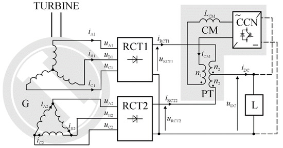
Figure 1.
Block diagram of basic part of energy conversion system with permanent magnet synchronous generator with modulated magnetic flux (PMSG-MF). The power electronics converter block (CCN) is powered from DC rails (optional). PT, power pulse transformer; L, load; RCT1 and RCT2, diode rectifier.
The proposed solution of the energy conversion system is intended mainly for medium and large capacity RES, where its advantages are particularly visible. The main objective of this system is to provide a high efficiency (effectiveness) of the conversion of mechanical energy into electricity by means of a relatively simple power electronics part. This effect gives the PMSG, with specially designed stator windings and a dedicated power electronics converter, the ability to obtain a sinusoidal magnetomotive force (mmf). A consequence of this is that the resultant magnetic flux is close to a sinusoidal wave. This allows the power loss in the “iron” of the generator to be limited, which, in addition to the loss in the “copper”, is one of the major power losses in the machine. The power electronics converter, connecting the generator to the DC circuit of the system, has a simplified design, which mostly uses uncontrolled (i.e., diode) rectifiers, instead of active (mostly, transistors-based) rectifiers, which provides high energy conversion efficiency. In small-to-medium power wind energy conversion systems, uncontrolled rectifiers rather than pulse width modulation (PWM)-based active rectifiers are widely implemented, due to the advantages of high reliability and low cost—see, for example, the work of [30].
In the presented case, there is a pair of three-phase windings in the stator, one of them connected in the “star” and the second in the “delta” configuration. The voltages at the terminals of both windings should have the same value. The windings are burdened by two independent six-pulse diode rectifiers (denoted as RCT1 and RCT2). A power electronics converter (i.e., the “current modulator”; CM) is included at the output of each rectifier, shaping their output currents (, ). The CM consists of three main parts: the power electronics converter block (CCN), output inductor (), and power pulse transformer (PT). All these elements make up the power electronics controlled current source. The CM generates the output current (), whose characteristics are defined later. This current flows through the primary winding of the pulse transformer (the PT block) with the secondary winding divided. The secondary winding of the transformer interconnects the outputs of both rectifiers, which means that changing the shapes of the output currents of both rectifiers is possible by applying the modulator output current flowing through the transformer.
The relationship between the diode rectifier’s output currents, the modulator’s current, and the direct current () is as follows [27,28,29]:
where and , —numbers of turns of the PT windings.
The primary objective of the current modulator operation is to obtain the proper shape of the phase currents of the PMSG, so that the resultant mmf, associated with a given pair of windings (“star”, “delta”), is a sinusoidal wave, which enables the power loss in its magnetic circuit to be minimized. This phenomenon is called “the modulation of the magnetic flux”, which refers directly to the principles of the current modulator operation. In order to obtain the sinusoidal shape of the mmf, the modulator output current must comply with the following equation, which is the generalized version of the formula used in [27,28,29]:
where is the frequency of the generator’s output voltage.
However, taking into account a three-phase electrical system, the current given by Formula (4) should be replaced by a current that has the same phase shift—in respect of a voltage in a given phase. So, the fundamental frequency of the current generated by the modulator should be equal to six times that of the generator output voltage frequency (). Very close to Formula (4) is the current with, e.g., a triangular shape [27,28,29]. This is given by the following equation:
The waveforms of the modulator current given by (4) and (5) are shown in Figure 2. Using (5) instead of (4) results in only a small increase in the deformation of the generator mmf with respect to the desired sinusoidal waveform.

Figure 2.
Shape of the current modulator (CM) current given by (4) and by (5).
Taking into account equation (5), the expected shape of the mmf will look like Figure 3. Thus, due to the current modulator operation, the resultant mmf associated with each pair of stator windings will be quasi-sinusoidal.
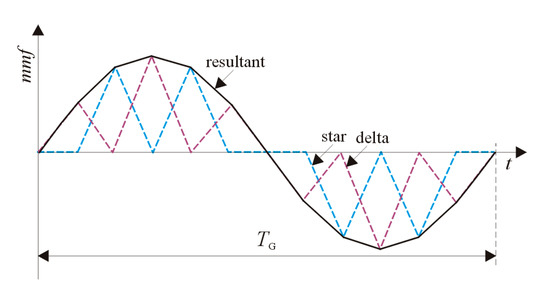
Figure 3.
Theoretical shape of magnetomotive force (mmf) associated with group of “star” and “delta” connections and the resultant mmf.
It is an important assumption for the proper operation of the current modulator that the system’s total output current () drawn by the load (L) is constant over time. Hence, it is necessary to automatically (i.e., by the dedicated control algorithm) adjust its magnitude by means of parameter of equation (5). From the point of view of the complexity of the system’s construction, one important feature is that the power of the modulator is very low, theoretically about 3.32% [28], in relation to the system’s nominal output power.
3. Energy Conversion System Basics of Operation
If the proposed system is designed to cooperate with the power grid, a dedicated converter connecting the system with this grid is necessary. Typically, this converter is a three-phase voltage source inverter (VSI). This role is fulfilled by the power grid converter (PCN) block in Figure 4. In such a system configuration, an inductor () should appear in its DC circuit. The purpose of the inductor is both to maintain the modulator output current continuity—which is necessary for obtaining proper operation of the CM—and to reduce ripples in this current, which are caused by the operation of the diode rectifiers. A large capacitor () is connected to the PCN input terminals.
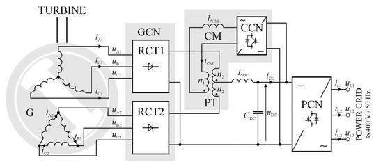
Figure 4.
Block diagram of the proposed energy conversion system. PCN, power grid side converter; GCN, generator side converter.
The demand for high output power of the PCN necessitates a suitable topology for this. In this case, an interleaved converters topology was chosen. In contrast to the usual parallel connection of power devices, this topology allows multiplication of the pulsation frequency (caused by the PWM carrier frequency) in the converter’s output current. This multiplication is done by the factor of where is the number of legs per converter phase. As a result of the converter operation, the magnitudes of the current ripples can be reduced significantly compared to the traditional (i.e., single-channel) converter solution [31,32]. In the case of the present work, it was assumed that = 3. The block diagram of the PCN is shown in Figure 5.
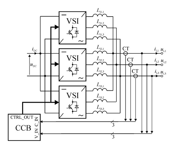
Figure 5.
Block diagram of the power grid side converter. CCB, control block; VSI, voltage source inverter.
A common issue of interleaved converters operation, depending on the possibility of unbalanced currents in particular converter channels, was solved in the work by means of the software control algorithm [33]. This algorithm was used in the converter’s control block—denoted in Figure 5 as the CCB. Details of all the system’s parameters are given in the following section.
4. Simulation Model Studies
The main aim of the study was to compare the efficiency of the power electronics part of the energy conversion system based on the proposed scenario—called the model of the novel system (MNS)—in relation to the “standard” energy conversion system—called the model of the standard system (MSS)—which uses a conventional three-phase PMSG. The basic efficiency analysis of the proposed PMSG-MF, in comparison to a conventional PMSG, was performed in [27]. Such a type of “standard” model was selected for the following reasons: some similarity of the PMSG-MF to the conventional PMSG, similar condition (mainly sinusoidal phase currents, which enforce close to a sine-wave mmf) of generator operation, and the popularity of PMSGs as part of RES. The converters used in this model were an active insulated gate bipolar transistor (IGBT)-based rectifier, providing the (quasi-)sinusoidal waveforms of the generator phase currents, and the power grid converter—also operating with close to sinusoidal output currents. The rated output power of both models was set at 1400 kW. Also, both systems operated at 3 × 400 V/50 Hz power grid. Additional remarks according to the simulation models are as follows:
- The detailed maximum power point tracking (MPPT) algorithm for a turbine operation was not taken into account;
- Due to low values of the PWM carrier frequencies, only fundamental Joule loss in passive elements of the power electronics converters (generator side converter (GCN), PCN, CM) was respected;
- The saturation of the magnetic circuits was omitted;
- The relatively low impact of current modulator power loss on the overall system efficiency meant that these were assumed as constant and equal to the nominal one, regardless of the value of the modulator output current;
- Regardless of the output power, the voltage in the DC circuit was almost constant—only voltage drops at serial impedances of the system were respected;
- The current modulator was powered from the common system’s DC rails;
- Most of the power electronics converters used were systems operating in a closed feedback loop, so their potential instability [34,35] can be an issue; in all the mentioned cases the output current regulators were P type and their gains were set at 50% of the maximal value permissible from the point of view of protecting a given system’s stability [36].
The power electronics sections of the models were built in the MATLAB and, partially, in the OrCAD/PSPICE environments.
The models of the main power devices were based on real components (manufactured by Mitsubishi Electric) as follows:
- High power diode and IGBT modules—used in the diode rectifiers and active bridges;
- Medium power IGBT/IPM modules—used in the current modulator.
These are listed in the following sub-section. For power loss calculation in the power modules, Mitsubishi Electric supplies software, developed by themselves, was used—Melcosim [37]. The latest available version (i.e., 5.4.0) of this environment was also used in the studies.
4.1. Topology and Parameters of the MNS
The block diagram of the MNS for simulation purposes is shown in Figure 6. The model of the entire energy conversion system consists of the following main blocks and components:
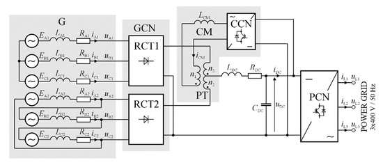
Figure 6.
Diagram of model of the novel system (MNS) used in the simulation studies.
- PMSG (G) with two three-phase windings (“star” and “delta” connection) in the stator;
- Generator side converter (GCN) with two diode rectifiers (RCT1, RCT2);
- Current modulator, with the suitable converter (CCN), powering the pulse transformer (PT);
- Power grid side converter (PCN)—in the form of an interleaved (three-channel) voltage source inverter.
The CCN is a single- or dual-channel (interleaved) voltage source inverter. Its block scheme is shown in Figure 8 in the next sub-section. The interleaved converters obtain a higher quality of output current, compared to single-channel solutions [31,32]. Details of the assumed parameters of the MNS are given in Table 1.

Table 1.
Parameters of the MNS for simulation purposes.
4.2. Topology and Parameters of the MSS
The block diagram of the energy conversion system used in the simulation studies is shown in Figure 7.
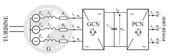
Figure 7.
Diagram of the model of standard system (MSS) in the simulation studies.
In the present case, the model of the system consists of the following main blocks and components:
- Three-phase conventional PMSG (G);
- Generator side converter (GCN)—in the form of an active rectifier;
- Power grid side converter (PCN).
The topologies of both converters (i.e., GCN and PCN) were the same and in line with Figure 5. The detailed parameters of the MNS are given in Table 2.
Table 2.
Parameters of the MSS for simulation purposes.
The models of the main power devices used in both models were based on the following components:
- RM1800HE-34S: 1700 V/1800 A—a diode module [38]—used in RCT1 and RCT2 (2 × 3 = 6 modules in total);
- CM1800DY-34S: 1700 V/1800 A—an IGBT module [38]—used in GCN and PCN (2 × 9 = 18 modules in total);
- PM150RL1A120 (1200 V/150 A) or PM100RL1A120: (1200 V/100 A)—an IGBT/IPM [38]—used in CM (the type and number of the modules depended on the version of the CCN, i.e., the number of its channels).
4.3. Results of Simulation Model Studies
All studies were conducted for the nominal frequency of the PMSGs’ output voltages. The reason for this was that this case of the system’s operation conditions can be treated as the “worst case”. The term “worst case” should be clarified here. The ability of the current modulator, as a power electronics device, to correctly map its output current in the input control (reference) signal deteriorates with increases in the frequency of the input signal. This results directly from the low-pass property (nature) of this device. In other words, the quality of the modulator operation is the lowest (i.e., the value of the control error, defined in the following text, is highest) for the rated Root Mean Square (RMS) value of the PMSG output voltage (i.e., the rated frequency of this voltage) which is accompanied with the rated generator’s rotation speed. For any lower value of this speed, the required frequency of the modulator output current (given by equation (5)) is also lower. Thus, the mapping of this current in the reference signal will be better compared to higher frequencies. Therefore, the nominal conditions of the generator’s operation impose the highest requirements on the power electronics devices.
First, the quality of the CM output current was evaluated. Also, comparative studies of the two versions of the CM were conducted, i.e., for both a single-channel ( = 1) and a dual-channel ( = 2) version of the CM. The block scheme of the dual-channel version of the CM (CCN) is shown in Figure 8.
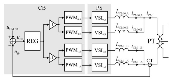
Figure 8.
Block scheme of the CM based on dual-channel converter (CCN).
The CCN (Figure 6) consists of two parts—control block (CB) and power stage (PS). The block denoted as REG is the output current regulator, while blocks are half-bridge inverters and CT is a current transducer. At the output of the PS, both the set of inductors and the pulse transformer are included. In the case of the single-channel version of CM blocks, , , and were excluded from the circuit.
The selected waveforms in the simulation model of the MNS (also for the nominal frequency of the CM output current, i.e., 58.5 Hz) are shown in Figure 9.
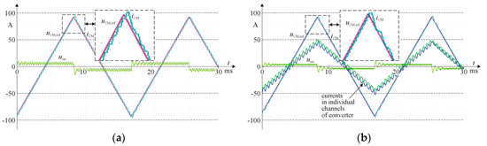
Figure 9.
Waveforms in the simulation model of the current modulator, where its output current is equal to the nominal value, in two versions of the CCN: (a) single-channel; (b) dual-channel (interleaved) converter.
The shapes of the modulator output current and its reference signal almost coincide. However, in transient states, these signals differ from each other. This occurrence is shown in the frames in Figure 9, which contain a magnified portion of the graph. The difference between the two signals is mostly the result of a limited “frequency response” (i.e., a pass-band) of the current modulator.
One of the suitable and reliable criteria of the CM’s current quality is the control error (), which is defined as
where , is the reference signal for the CM and is the transfer ratio of the CT.
In the nominal conditions of the CM operation: = 2.0% ( = 1), = 1.1% ( = 2). Thus, in the case of the dual-channel converter, the error value is equal to 55% of the error associated with the single-channel converter operation. For that reason, the value of this error affects the value of the power loss in the “iron” of the PMSG, so this value should be kept as low as possible [27]. In the case of the dual-channel topology of the CM, the power losses in this block are reduced by 0.5%.
Figure 10 shows samples of the mmf in the stator of the PMSG as the result of the CM operation. For better visibility of the waveforms in Figure 10b, the magnitudes of these are enlarged ten-fold.
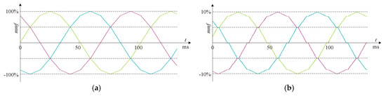
Figure 10.
Mmfs in the stator of the PMSG when its output power is equal to a nominal value (a) and 10% of this value (b).
In turn, Figure 11 presents the waveforms of the currents in individual inverter channels, the reference grid current, and the resultant grid current for one phase of the PCN.
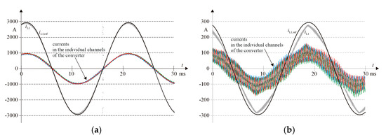
Figure 11.
Waveforms of currents in individual inverter channels, reference grid current (black), and resultant power grid current (grey)—for one phase of PCN—when its output power is equal to the nominal value (a) and 10% of this value (b).
In the following part of the section, the calculated efficiencies (,) of both simulation models are presented. The total power loss in the two models is given in Table 3 and Table 4. The power loss concerns the dual-channel configuration of the CCN (as the part of the MNS). In general, the efficiency factor () of the system is defined as follows:
where is the system’s output power and is the total power system’s loss.
Table 3.
Power loss and system’s efficiency in the MNS.
Table 4.
Power loss and system’s efficiency in the MSS.
In Figure 12, the calculated curves of the simulation models’ efficiency for both the MNS and the MSS vs. the system’s relative output power are presented.
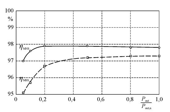
Figure 12.
Efficiency of MNS and MSS vs. system’s relative output power.
The research has shown that the efficiency of the power electronics part of the proposed system is equal to 97.0~97.9% and is about 0.5~1.9% higher compared to a system equipped with a full-power active rectifier. Moreover, when the output power is in the range of 20~100% of the nominal one, the efficiency curve is flat. This is an important advantage of the proposed power system because it is rare for the RES to operate in the nominal conditions [39].
5. Laboratory Tests of Current Modulator
The main aim of the laboratory experiments was to validate the theoretical assumptions and research results of the power system simulation model, in the sense of evaluating the quality of the modulator output current. The block diagram of the laboratory model of the CM was consistent with the diagram shown in Figure 8. During the tests, the secondary windings of the PT were short-circuited. The basic technical parameters of the laboratory prototype of the CM are given below:
- ▪
- DC link voltage in CCN block converter: 100 V;
- ▪
- Nominal magnitude of the modulator output current: 12 A;
- ▪
- Inductance of the single coil in the CM: 1.15–1.27 mH;
- ▪
- Sampling frequency in the control block: 20 kHz;
- ▪
- PWM carrier frequency: 10 kHz.
This modulator is intended for use in a system with the nominal output power up to 18 kW. Figure 13 presents the equivalent circuit of the PT. The values of all the components were calculated in an experimental way [40]. The PT offers very good values of its electrical parameters. All parasitic capacitances, which exist in every real transformer, were omitted due to their negligible impact on the circuit operation, which was verified in an experimental way also.
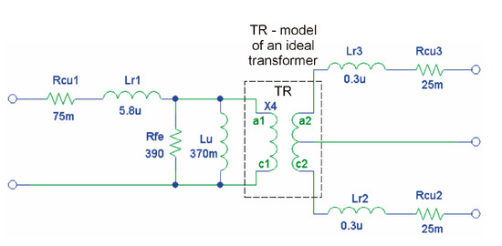
Figure 13.
Equivalent circuit of the pulse transformer.
The control block in the laboratory prototype was based on the ALS-G3-1369 DSP evaluation kit [41] with Analog Devices Inc. ADSP-21369 SHARC® DSP. This system is specialized for such power electronics and industrial measurement applications, which require both high computation power of the CPU and high precision (in the sense of resolution) of the PWM signal generation unit. In the power stage of the modulator prototype, two P3-5-550MFE LABINVERTERs [41] were used. These universal power electronics converters are designed especially for R&D applications. The general view of the laboratory stand is shown in Figure 14.
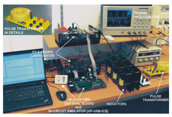
Figure 14.
View of the laboratory stand during tests.
Tests of the laboratory model were carried out with the CM output current magnitude in the range of 10~100% of the rated value. Also, two cases of converter configuration were tested, i.e., single- and dual-channel. Figure 15 and Figure 16 show the exemplary waveforms in the laboratory prototype of the CM. For better visibility of the error signal waveform, its magnitude was enlarged. Also, these figures contain magnified portions of the graphs.
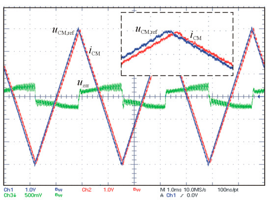
Figure 15.
Selected waveforms in the laboratory prototype of the current modulator, with the CM operating in a single-channel configuration. The modulator’s output current magnitude is equal to the nominal one. Horizon scale = 1 ms/div, vertical scale = 4A (4V)/div (2 V/div for the error signal).
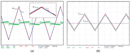
Figure 16.
Selected waveforms in the laboratory prototype of the current modulator, with the CM operating in a dual-channel configuration (a). In (b) the currents in the individual channels of the modulator are shown. The modulator’s output current magnitude is equal to the nominal one. Horizon scale = 1 ms/div, vertical scale = 4A (4V)/div (2 V/div for the error signal).
Assuming the nominal conditions of the model operation, the value of the measured control error was as follows: = 4.8% ( = 1) and = 2.5% ( = 2). Thus, in the sense of the value of the control error criterion, the dual-channel CM makes it possible to improve the quality of its output current close to two-fold compared to the single-channel version. The relatively high value of the control error, compared to the results of the simulation model studies, was caused mainly by errors (e.g., offset, non-linearity) coming from the real devices, i.e., the current transducer and magnetic elements, implemented in the experimental system.
6. Conclusions
The main objective of the presented system is to provide a high efficiency of the conversion of mechanical energy into electricity by means of relatively simple power electronics devices. This effect gives the PMSG, with a pair of “star” and “delta” windings in the stator. The two winding sets operate in a six-phase mode. To the output terminals of the machine, a pair of diode rectifiers is connected. In turn, in the DC circuit of the system the current modulator (i.e., the controlled current source) is included; this one generates a current about a triangular shape. The ability of such system is to obtain a sinusoidal magnetomotive force in the machine. A consequence of this is that the resultant magnetic flux is close to a sine-wave. This allows the power loss in the “iron” of the PMSG to be limited. Also, the dynamic power loss, caused by the hard switching power electronics devices (IGBT), was clearly reduced compared to the popular system equipped with a full-power active rectifier, cooperating with the PMSG, whereas the static power loss of the system decreases with decrease of the system output power. So, compared to an energy conversion system that uses a generator cooperating with an active rectifier, the proposed solution enables an increase in its resultant efficiency. The research showed that the efficiency of the power electronics part of the proposed system is higher by about 0.5–1.9%, compared to a system equipped with an active rectifier. Moreover, when the output power is in the range of 20–100% of the nominal value, the efficiency curve is flat. This is an important advantage of this energy conversion system because it is rare for RES to operate in the rated conditions. Given the solutions, in relation to other systems for renewable energy sources, the following features are also expected: increase in the reliability of operation, reduction of the maintenance costs, and the ability to meet the EMC requirements more easily. The studies also indicated that the cost of making such system should be lower than most other solutions for RES.
In the part of the studies devoted to the laboratory experiments, the current modulator prototype’s operation was positively verified too. For example, the dual-channel (interleaved) topology of the converter in modulator enables the quality of its output current to increase almost two-fold (in the sense of defined in the work criterion), compared to its single-channel version. Also, the power loss in the converter based on the interleaved topology was reduced, compared to the single-channel converter’s solution. The modulator’s output power remains at a very low level (a few percent) in relation to the system’s nominal power. The disadvantage of the proposed energy conversion system is that this system needs some minimal value of voltage in the DC circuit (i.e., the minimal value of the rotation speed of the turbine) to be able to transfer the electricity to the power grid. It results from the fact that no BOOST converter is present in the DC circuit.
The results of the research using the simulation model confirmed the theoretical assumptions adopted in the course of the study on the proposed energy conversion system. It should also be noted that the presented energy conversion system is also suitable for cooperation with water turbines and other types of turbines (not necessarily related to RES), with no significant changes needed to its basic power electronics section.
Author Contributions
Conceptualization, M.G. and M.K.; Formal analysis, R.S.; Investigation, M.K. and Ł.C.; Methodology, M.G. and R.S.; Software, M.K. and Ł.C.; Validation, M.G. and R.S.; Visualization, Ł.C.; Writing—original draft, M.G. and M.K.; Writing—review & editing, M.G. All authors have read and agreed to the published version of the manuscript.
Funding
This work was supported by Robotics and Electrical Engineering, Faculty of Control, Poznan University of Technology and LINTE^2 Laboratory, Gdansk University of Technology.
Conflicts of Interest
The authors declare no conflict of interest
Acronyms
| AC | alternating current. |
| CB or CCB | control block. |
| CCN | power electronics converter block. |
| CM | current modulator. |
| CPU | central processing unit. |
| DSP | digital signal processor. |
| CT | current transducer. |
| DC | direct current. |
| DD | direct drive generators. |
| DFIG | doubly fed induction generator. |
| EESG | electrically excited synchronous generator. |
| EMC | electromagnetic compatibility. |
| G | generator. |
| GCN | generator side converter. |
| IGBT | insulated gate bipolar transistor. |
| IPM | intelligent power module. |
| L | load. |
| mmf | magnetomotive force. |
| MNS | model of novel system. |
| MPPT | maximum power point tracking. |
| MSS | model of standard system. |
| PCN | power grid converter. |
| PMSG | permanent magnet synchronous generator. |
| PMSG-MF | permanent magnet synchronous generator with modulated magnetic flux. |
| PS | power stage. |
| PT | power pulse transformer. |
| PWM | pulse width modulation. |
| RCT1, RCT2 | diode rectifier. |
| R&D | research and development. |
| REG | regulator. |
| RES | renewable energy sources. |
| SCIG | squirrel cage induction generator. |
| SG | synchronous generators. |
| TR | transformer. |
| VSI | voltage source inverter. |
References
- Global Wind Report 2019|Global Wind Energy Council. Available online: https://gwec.net/global-wind-report-2019/ (accessed on 26 April 2020).
- Nehrir, M.; Wang, C.; Strunz, K.; Aki, H.; Ramakumar, R.; Bing, J.; Miao, Z.; Salameh, Z. A review of hybrid renewable/alternative energy systems for electric power generation: Configurations, control, and applications. IEEE Trans. Sustain. Energy 2011, 2, 392–403. [Google Scholar] [CrossRef]
- Boldea, I. Electric Generators Handbook—Two Volume Set; CRC Press LLC: Boca Raton, FL, USA, 2015. [Google Scholar]
- Akinrinde, A.; Swanson, A.; Tiako, R. Dynamic behavior of wind turbine generator configurations during ferroresonant conditions. Energies 2019, 12, 639. [Google Scholar] [CrossRef]
- Zribi, M.; Alrifai, M.; Rayan, M. Sliding mode control of a variable-speed wind energy conversion system using a squirrel cage induction generator. Energies 2017, 10, 604. [Google Scholar] [CrossRef]
- Semken, S.R.; Polikarpova, M.; Röyttä, P.; Alexandrova, J.; Pyrhänen, J.; Nerg, J.; Mikkola, A.; Backman, J. Direct-drive permanent magnet generators for high-power wind turbines: Benefits and limiting factors. IET Renew. Power Gener. 2012, 6, 1–8. [Google Scholar] [CrossRef]
- Niu, S.; Liu, Y.; Ho, S.; Fu, W. Development of a novel brushless power split transmission system for wind power generation application. IEEE Trans. Magn. 2014, 50, 1–4. [Google Scholar] [CrossRef]
- Liu, Y.; Niu, S.; Fu, W. A novel multiphase brushless power-split transmission system for wind power generation. IEEE Trans. Magn. 2016, 52, 1–7. [Google Scholar] [CrossRef]
- Goudarzi, N.; Zhu, W. A review on the development of wind turbine generators across the world. Int. J. Dyn. Control 2013, 1, 192–202. [Google Scholar] [CrossRef]
- Gupta, A.; Jain, D.K.; Dahiya, S. Some investigations on recent advances in wind energy conversion systems. In Proceedings of the 2012 IACSIT Coimbatore Conferences, Singapore, 18–19 February 2012; Volume 28, pp. 47–52. [Google Scholar]
- Khan, M.S.U.; Maswood, A.I.; Tariq, M. Operation of parallel unity power factor passive front end rectifier for PMSG based offshore wind turbine system. In Proceedings of the 2016 IEEE International Conference on Power Electronics, Drives and Energy Systems, Trivandrum, India, 14–17 December 2016. [Google Scholar]
- Blesslin, A.A.; Anish, K.J. Modified rectifier topology for high power PMSG variable speed wind turbine. Int. J. Adv. Res. Electr. Electron. Instrum. Eng. 2015, 4, 1665–1672. [Google Scholar]
- Iacchetti, M.; Foglia, G.; di Gerlando, A.; Forsyth, A. Analytical evaluation of surface-mounted PMSG performances connected to a diode rectifier. IEEE Trans. Energy Convers. 2015, 30, 1367–1375. [Google Scholar] [CrossRef]
- Liang, C.; le Claire, J.; Aït-Ahmed, M.; Benkhoris, M. Power control of 5-phase PMSG-diode rectifier-interleaved boost set under health and fault modes. Electr. Power Syst. Res. 2017, 152, 316–322. [Google Scholar] [CrossRef]
- Lee, J.; Lee, K. Predictive control of Vienna rectifiers for PMSG systems. IEEE Trans. Ind. Electron. 2017, 64, 2580–2591. [Google Scholar] [CrossRef]
- Yanghong, T.; Haixia, Z.; Ye, Z. A simple-to-implement fault diagnosis method for open switch fault in wind system PMSG drives without threshold setting. Energies 2018, 11, 2571. [Google Scholar] [CrossRef]
- Zoghlami, M.; Kadri, A.; Bacha, F. Analysis and application of the sliding mode control approach in the variable-wind speed conversion system for the utility of grid connection. Energies 2018, 11, 720. [Google Scholar] [CrossRef]
- Tiwari, R.; Krishnamurthy, K.; Neelakandan, R.B.; Padmanaban, S.; Wheeler, P.W. Neural network based maximum power point tracking control with quadratic boost converter for PMSG—Wind energy conversion system. Electronics 2018, 7, 20. [Google Scholar] [CrossRef]
- Pantea, A.; Yazidi, A.; Betin, F.; Capolino, G.A.; Lanfranchi, V. Six-phase axial flux permanent magnet generator model: Simulation and experimental validation. In Proceedings of the IEEE 25th International Symposium on Industrial Electronics (ISIE), Santa Clara, CA, USA, 8–10 June 2016. [Google Scholar]
- Zhou, S.; Rong, F.; Yin, Z.; Huang, S.; Zhou, Y. HVDC transmission technology of wind power system with multi-phase PMSG. Energies 2018, 11, 3294. [Google Scholar] [CrossRef]
- Schmidt, E.; Sušić, M.; Eilenberger, A. Design studies on a permanent magnet synchronous machine with Y- and Δ-connected stator winding. IEEE Trans. Magn. 2011, 47, 1042–1045. [Google Scholar] [CrossRef]
- Vansompel, H.; Sergeant, P.; Dupre, L.; Bossche, A. A Combined delta-delta connection to increase the performance of axial-flux PM machines with concentrated windings. IEEE Trans. Energy Convers. 2012, 27, 403–410. [Google Scholar] [CrossRef]
- Zawilak, T.; Gwozdziewicz, M. Limitation of higher harmonics in line start permanent magnet synchronous motor by star-delta mixed stator winding. In Proceedings of the IET 8th International Conference on Computation in Electromagnetics (CEM 2011), Wroclaw, Poland, 11–14 April 2011; pp. 1–2. [Google Scholar]
- Mohapatra, K.; Kanchan, R.; Baiju, M.; Tekwani, P.; Gopakumar, K. Independent field-oriented control of two split-phase induction motors from a single six-phase inverter. IEEE Trans. Ind. Electron. 2005, 52, 1372–1382. [Google Scholar] [CrossRef]
- Luo, Q.; Zheng, J.; Sun, Y.; Yang, L. Optimal modeled six-phase space vector pulse width modulation method for stator voltage harmonic suppression. Energies 2018, 11, 2598. [Google Scholar] [CrossRef]
- Krystkowiak, M.; Gwóźdź, M. Energy conversion system for wind and water turbines based on generator with modulated magnetic flux. In Proceedings of the 2018 Progress in Applied Electrical Engineering (PAEE), Małopolskie, Poland, 18–22 June 2018. [Google Scholar]
- Gwóźdź, M.; Krystkowiak, M.; Jędryczka, C.; Gulczyński, A.; Matecki, D. Generator with modulated magnetic flux for wind turbines. Bull. Pol. Acad. Sci. Tech. Sci. 2017, 65, 469–478. [Google Scholar] [CrossRef]
- Choi, S.; Enjeti, P.; Hoag-Hee, L.; Pitel, I. A new active interphase reactor for 12-pulse rectifiers provides clean power utility interface. IEEE Trans. Ind. Appl. 1996, 32, 1304–1311. [Google Scholar] [CrossRef]
- Strzelecki, R.; Supronowicz, H. Power Factor in AC Power Supply Systems and Methods for Its Improvement; Publishing House of the Warsaw University of Technology: Warsaw, Poland, 2000. (In Polish) [Google Scholar]
- Chen, J.; Chen, J. On reducing the shaft torque ripple of small-to-medium-scale wind energy conversion systems using multi-pulse autotransformer rectifier. Energies 2018, 11, 379. [Google Scholar] [CrossRef]
- Rozanov, Y.; Ryvkin, S.; Chaplygin, E.; Voronin, P. Fundamentals of Power Electronics: Operating Principles, Design, Formulas, and Applications; CRC Press: Boca Raton, FL, USA, 2015. [Google Scholar]
- Muhammad, H.R. Power Electronics Handbook; Elsevier Ltd.: Oxford, UK, 2018. [Google Scholar]
- Gwóźdź, M. Controller for balancing of current distribution in multi-channel converters. In Proceedings of the Progress in Applied Electrical Engineering (PAEE), Kościelisko, Poland, 26 June–1 July 2016. [Google Scholar]
- Doyle, J.; Francis, B.A.; Tannenbaum, A.R. Feedback Control Theory; Courier Corporation: North Chelmsford, MA, USA, 2013. [Google Scholar]
- Hasegawa, Y. Control Problems of Discrete-Time Dynamical Systems; Springer: Berlin/Heidelberg, Germany, 2016. [Google Scholar]
- Gwóźdź, M. Stability of discrete time systems on base of generalized sampling expansion. Q. Elektr. 2011, 1, 29–40. [Google Scholar]
- MITSUBISHI ELECTRIC Global Website. Available online: http://www.mitsubishielectric.com/semiconductors/simulator/index.html (accessed on 27 April 2020).
- MITSUBISHI ELECTRIC Global Website. Available online: http://www.mitsubishielectric.com/semiconductors/products/powermod/index.html (accessed on 27 April 2020).
- Renewable Energy World. Available online: http://www.renewableenergyworld.com/wind-power/tech.html (accessed on 27 April 2020).
- Krystkowiak, M.; Gwóźdź, M. Calculation of parameters of equivalent circuit of pulse transformer. In Proceedings of the XX Symposium Electromagnetic Phenomena in Nonlinear Circuits, Lille, France, 2–4 July 2008. [Google Scholar]
- Available online: http://analog.alfine.pl/oferta/produkty-alfine/systemy-uruchomieniowe/limitstart=0 (accessed on 27 April 2020).


© 2020 by the authors. Licensee MDPI, Basel, Switzerland. This article is an open access article distributed under the terms and conditions of the Creative Commons Attribution (CC BY) license (http://creativecommons.org/licenses/by/4.0/).