Article

Distributed Hierarchical Consensus-Based Economic Dispatch for Isolated AC/DC Hybrid Microgrid

College of Energy and Electrical Engineering, Hohai University, Nanjing 211100, China
*
Author to whom correspondence should be addressed.
Energies 2020, 13(12), 3209; https://doi.org/10.3390/en13123209
Submission received: 12 May 2020 / Revised: 15 June 2020 / Accepted: 16 June 2020 / Published: 20 June 2020

Abstract

:
In this paper, a distributed hierarchical consensus algorithm is proposed to solve the economic dispatch (ED) problem for the isolated AC/DC hybrid microgrid. At first, the whole nodes of the AC/DC hybrid microgrid are divided into two parts, that is, the leadership layer nodes and the tracking layer nodes. The leadership layer nodes update the data through their own feedback elements, while the tracking layer nodes receive the information from the leadership layer nodes and update the data. After several iterations, the two different layer nodes obtain the same state, which realizes the dynamic active power balance of the whole AC/DC microgrid. Besides, the AC sub-grid and DC sub-grid can also realize the power balance by the proposed algorithm, and the energy storage units will absorb or release active power to meet the power demand in the respective section. In addition, the constraints of the nodes are also taken into account to guarantee that the power nodes in the AC/DC hybrid microgrid should operate within their own limitations, which is necessary to realize the ED for the considered hybrid microgrid. Finally, case study and simulation results are provided to illustrate the effectiveness of the proposed hierarchal method.

1. Introduction

As an effective way of integrating distributed power generations and load, microgrids have obtained more and more attention as applications [1,2,3,4]. Due to the microgrid containing various distributed power sources, such as photovoltaic (PV), wind turbine (WT), and so on, the distributed power sources have their own different characteristics. The traditional control methods will be invalid to be used to solve the control problem of microgrids. Therefore, some new control strategies must be studied to deal with the microgrid control method. As of now, there are several results to realize the different control strategies in microgrids [5,6].
The traditional centralized control method needs a control center, through which the control order is sent. The receiving element obtains the signal sent from the control center and makes a process, then executes the relevant actions. However, with the large number of distributed power sources permeating into the microgrid, the traditional centralized control strategies may be ineffective to realize satisfactory results. On the other hand, once the control center is out of service, the whole system will be unable to work, which means an enormous loss. The distributed control method can easily avoid the above problem, the main reason being that the distributed control strategy does not need the control center, it is just used for the information exchange between one unit and its neighbors, finally obtaining a whole system of information sharing. If one or more of the units are out of service, the rest of the units can continue to process the information exchange, finally resulting in complete information sharing. Therefore, compared with the traditional control methods, the distributed control strategies are superior [7,8]. In this paper, the distributed control method is utilized to solve the economic dispatch (ED) problem of the AC/DC hybrid microgrid.
On the other hand, with the rapid development of microgrid technology, the connection is closing between power grids, especially the relationship between the AC microgrid and the DC microgrid. Due to these two microgrids having different characteristics, the control methods and optimizing strategies are disparate. But the final goals are similar, that is, maintain the microgrid operating in a balanceable and safe state. The information exchange of the AC/DC hybrid microgrid is complicated and bidirectional, which is a challenging work.
In addition, the ED problem is significant for keeping the normal operation of the microgrid, and the rational dispatch is beneficial to reduce cost and increase profits. By power dispatching, the power demands between loads and generators are satisfied, and the stability of the power grid is enhanced. With the development of distributed control technology, the distributed consensus strategies are widely used to solve the ED problem. The proposed distributed method is also an exploration to realize the rational ED for the AC/DC microgrid.

2. Literature Review

It should be pointed out that the distributed consensus strategies have become promising technologies after decades of development. Up to now, there have been a large number of results about the applications of distributed control strategies. In Reference [9], by using the consensus algorithm, for an island microgrid, the optimal resource management strategy was presented. In Reference [10], the authors studied the power balance problem of the DC microgrid by using the consensus method. In References [11,12], the consensus algorithms were presented for solving the problems of the voltage stability and compensation in the microgrid, respectively. But the above references do not refer to the distributed hierarchical control thought. In Reference [13], for the DC microgrid, the distributed hierarchical control method was designed. A three-layer control framework for the static and dynamic performance of the microgrid was proposed in Reference [14]. In Reference [15], the distributed hierarchical control problem of the island microgrid was solved by proposing a network control scheme based on a robust communication algorithm. In Reference [16], by linearizing the input and output feedback, the second-order voltage problem in the microgrid was transformed into a second-order linear synchronization tracking problem, and a distributed hierarchical control strategy was developed. In Reference [17], a hierarchical control structure was developed for an autonomous microgrid, which could effectively adjust the photovoltaic output and realize the active balance in the considered microgrid. In Reference [18], for solving the problem of active regulation of the autonomous microgrid, the authors designed a two-stage controller and the optimal active power regulation controller. Although the above references are related to the hierarchical control thought, the object is simple microgrids, which does not involve the AC/DC hybrid microgrid.
With the development of research, many researchers have transferred their attention to the AC/DC hybrid microgrid. By using different study methods, more and more results about the AC/DC hybrid microgrid have been published [19,20,21,22,23,24,25,26,27,28,29,30,31]. In References [20,21], the voltage control problem was investigated by using different methods in the AC/DC hybrid microgrid. In References [22,23,24], the problems of power control and management of the AC/DC hybrid microgrid were discussed through different methods. For the interconnected microgrids, the authors designed an event-based consensus strategy for solving the coordinated power sharing problems in Reference [25]. In Reference [26], for solving the reactive power sharing and DC current sharing problem in the considered hybrid microgrids, a distributed coordination control method was developed. In References [27,28], two different bidirectional interlinking converters were studied for enhancing the transient performance of an islanded AC-DC hybrid microgrid. In Reference [29], an appropriate combinatorial optimization technique was proposed for solving the optimal sizing problem of AC-DC hybrid microgrids. In Reference [30], a straightforward and efficient method was studied to solve power flows’ simultaneous problem of AC/DC hybrid microgrids.
On the other hand, as the basis for ensuring the economic and reliable operation of microgrids, the economic dispatch (ED) problem has also attracted special attention, and lots of results based on consensus algorithms have been developed [32,33]. In Reference [34], for solving the ED problem, the authors proposed a consensus-based algorithm for learning about the mismatch. In Reference [35], for the islanded microgrids, a new consensus-based method was developed, where the incremental cost of every agent is taken as the consensus variable, so their proposed method could quickly converge to the optimal solutions. In Reference [36], for solving the ED issue, an improved distributed consensus algorithm was proposed, where the feedback gains of the algorithm could be different and time varying. In Reference [37], considering the delay effect in the optimal operation of microgrids, the ED problem was discussed based on the consensus algorithm. In Reference [38], in the framework of hierarchical distributed theory, considering the power limitation of the DC microgrid, a constrained economic dispatch method was proposed. As for the ED problem for the AC/DC hybrid microgrid, some results have been developed. In Reference [39], for the considered hybrid microgrid, by considering the properties of AC and DC subsystems and the deficiencies in concentrated optimization, a management system based on consensus and coordination optimization was developed for the safe and economic operation. For discussing the economic operation of the hybrid AC/DC microgrid, a distributed control framework was proposed in Reference [40]. In References [41,42], a distributed economic dispatch method was developed based on the so-called finite-step consensus method, which could reach to the optimal solutions in finite steps. However, up to now, there are few results discussing hierarchical distributed strategy for the ED problem of the AC/DC hybrid microgrid. By fully taking into account the characteristics of the AC sub-grid and the DC sub-grid, how to connect the relationship between them and propose a reasonable control algorithm is an important issue for solving the ED problem for the AC/DC hybrid microgrid, which is an interesting and challenging topic.
Based on the above analysis and discussions, in this paper, a distributed two-layer consensus algorithm is proposed to investigate the ED problem of the AC/DC hybrid microgrid in detail. At first, the whole nodes of the AC/DC hybrid microgrid will be divided into two parts, that is, the leadership layer nodes and the tracking layer nodes. Then, by using the proposed consensus strategy, the data of the leadership layer and the tracking layer are uniformly processed to achieve the same increment cost (IC) of each node, which means that the ED problem is realized. Finally, some case study results and discussions are presented to demonstrate the usefulness of the developed hierarchical strategy.
The remainder of the article is arranged as follows: The optimal scheduling model for the considered AC/DC hybrid microgrid is presented in Section 3. In Section 4, for solving the ED problem, the two-layer consensus algorithms are proposed with or without constraints, respectively. In Section 5, the case study is designed to demonstrate the usefulness of the proposed distributed method. In the end, our main conclusions are given in Section 6.

3. Optimal Scheduling Model for the AC/DC Hybrid Microgrid

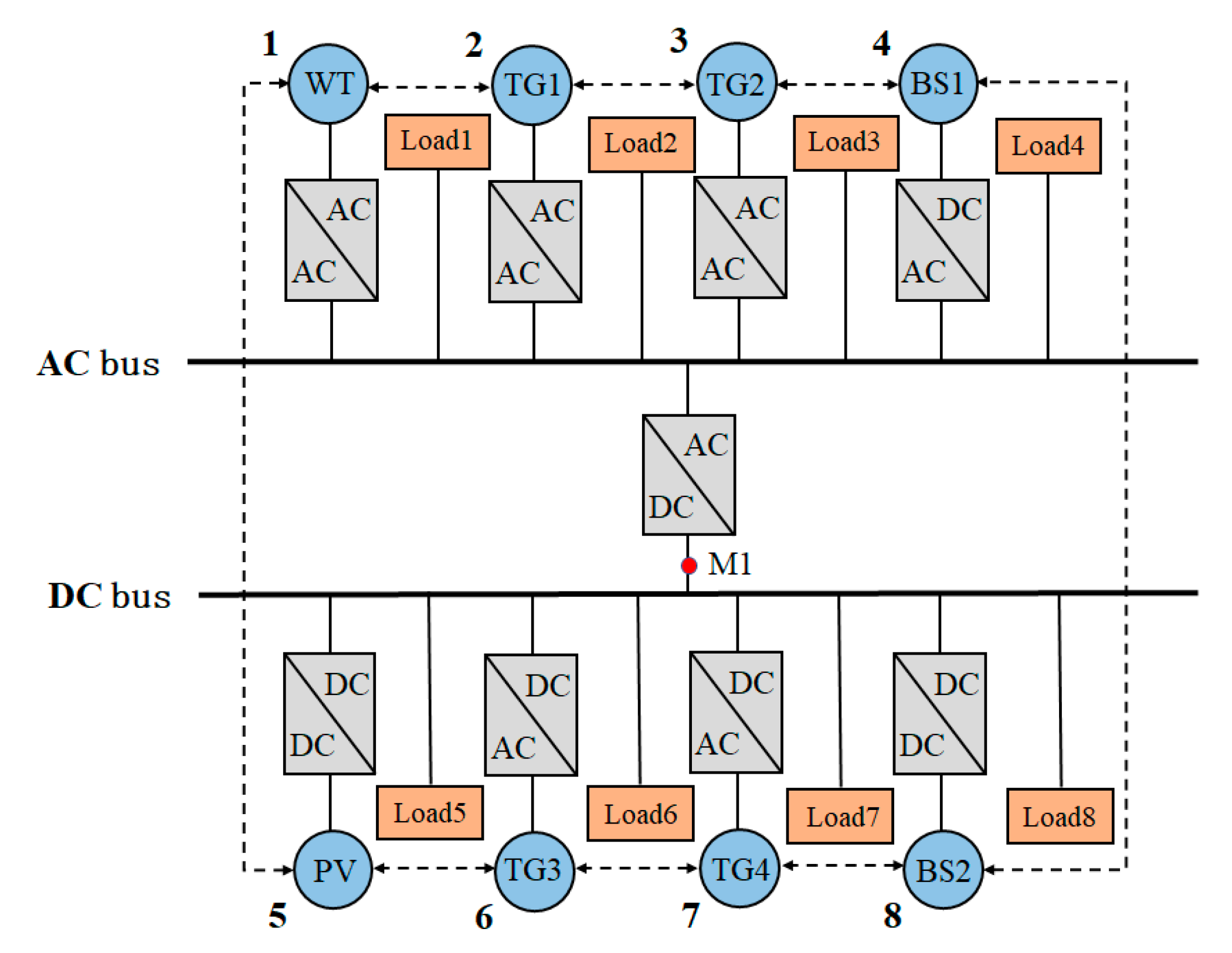
3.1. Structure Information of the AC/DC Hybrid Microgrid

In this paper, we mainly focus on the isolated AC/DC hybrid microgrid. Figure 1 presents the structure information of the considered model in this paper, which mainly contains an AC sub-grid, a DC sub-grid, and a power conversion unit that is in-lined between sub-grids. The wind turbine (WT) is connected to the micro-grid AC bus, and the solar photovoltaic unit (PV) is connected to the micro-grid DC bus, while the energy storage unit (BS) and the AC/DC load unit (Load) are in both parts. The AC sub-grids and DC sub-grids are connected by an AC/DC bidirectional converter (IC) between the AC bus and the DC bus, and M1 is an AC/DC tie line power monitoring point. The dashed lines in Figure 1 indicate the communication links between the various units.
To promote the utilization efficiency of the renewable energy and ensure reliable power supply, the operation of the isolated AC/DC hybrid microgrid is able to be grouped into three levels: (1) The distributed generations in the AC sub-grid and DC sub-grid are used for realizing power self-balancing in the region, (2) through the commutation tie line, the AC sub-grid and DC sub-grid can realize inter-area power balance, and (3) the electric energy transfer and peak-shaving are realized by charging and discharging the energy storage unit.

3.2. ED Model for the AC/DC Hybrid Microgrid

3.2.1. Objective Function

For the isolated microgrid, the dynamic economic dispatch strategy is based on the fact that all the distributed power supply equipment costs are fixed; meanwhile, the energy storage units can absorb or release power through their charging or discharging process. The objective function is formulated as
min ( t = 1 T [ i S T G C i ( P T G , i ( t ) ) + j S W T C j ( P W T , j ( t ) ) + k S S L C k ( P S L , k ( t ) ) + r S B S C r ( P B S , r ( t ) ) ] )
where T is the number of time periods in the daily dispatching cycle. STG and SWT are the sets of TG units and WT units, respectively. SSL is the set of PV units, and SBS represents the set of BS units. PTG,i(t), PWT,j(t), PSL,k(t), and PBS,r(t) are the active output power of the ith TG, jth WT, kth PV, and rth BS over a time period t, respectively. Ci(PTG,i(t)), Cj(PWT,j(t)), Ck(PSL,k(t)), and Cr(PBS,r(t)) are the generation cost/penalty functions of the corresponding unit set, respectively.

Traditional Generator Set Power Generation Cost Function

Without loss of generality, for a traditional generator set, the operating cost function can be modeled as the following quadratic function form [43]
C i ( P T G , i ( t ) ) = a T G , i ( P T G , i ( t ) ) 2 + b T G , i P T G , i ( t ) + c T G , i , i S T G
where a T G , i , b T G , i , and c T G , i represent the cost function coefficients.

Wind Generator and Photovoltaic Unit Abandonment Wind Penalty Function

The wind and solar penalty functions are formulated as
C j ( P W T , j ( t ) ) = a W T , j [ P W T , j ( t ) P W T , j s t ( t ) ] 2 + b W T , j [ P W T , j ( t ) P W T , j s t ( t ) ] + c W T , j , j S W T
C k ( P S L , k ( t ) ) = a S L , k [ P S L , k ( t ) P S L , k s t ( t ) ] 2 + b S L , k [ P S L , k ( t ) P S L , k s t ( t ) ] + c S L , k , k S S L
where a S L , k , b S L , k , c S L , k and a S L , k , b S L , k , c S L , k are the cost coefficients of abandoned wind and light respectively, and P W T , j s t ( t ) and P S L , k s t ( t ) are the maximum value of the adjustable power of the jth WT and the kth PV at the moment t, respectively.

Energy Storage Unit Operating Cost Function

The operating cost function for the energy storage unit is represented as an over-origin quadratic function with an opening up of
C r ( P B S , r ( t ) ) = a B S , r ( P B S , r ( t ) ) 2 + b B S , r P B S , r ( t ) + c B S , r , r S B S
where a B S , r , b B S , r , c B S , r denotes the coefficient of cost function.

3.2.2. Constraint Conditions

For the safe and stable operation, some operational constraints, for instance, the supply and demand balance constraints of each unit, should be taken into account.

Constraints for Active Supply and Demand Balance

The supply–demand balance constraint for the considered hybrid microgrid is formulated as
i S T G P T G , i ( t ) + j S W T P W T , j ( t ) + k S S L P S L , k ( t ) + r S B S P B S , r ( t ) = s S D M P D M , s ( t )
where S D M is the set of all load cells in the AC/DC hybrid microgrid, and P D M , s ( t ) is the load demand value of load unit s at the moment t. Besides, the DC sub-grid and AC sub-grid of the microgrid must also meet the constraints of the active balance equation.
a. Constraint for DC side active balance:
k S S L P S L , k ( t ) + r S B S P B S , r ( t ) + P A C D C ( t ) = s S D C D M P D C D M , s ( t )
where P A C D C ( t ) is the interaction power between the AC and DC sub-grids through the commutation line and S D C D M is the set of DC load cells.
b. Constraints for AC side active balance:
i S T G P T G , i ( t ) + j S W T P W T , j ( t ) P A C D C ( t ) = s S A C D M P A C D M , s ( t )
where S A C D M is the set of AC load cells, and P A C D M , s ( t ) is the load value of DC load unit s at moment t.

Constraints for Traditional Generator Set Operation

a. Active power upper and lower bound:
P T G , i min ( t ) P T G , i ( t ) P T G , i max ( t )
where P T G , i min ( t ) and P T G , i max ( t ) are the active adjustable lower limit and upper limit of the conventional generator set at the moment t , respectively.
b. Constraint for output climbing:
Δ P T G , i d P T G , i ( t ) P T G , i ( t 1 ) Δ P T G , i u
where Δ P T G , i u and Δ P T G , i d are the maximum of active power during the time period [ t 1 , t ] of the traditional generator set i.

Constraints for Operating the Energy Storage Unit

a. Charging and discharging power upper and lower bounds:
P _ B S , r P B S , r ( t ) P ¯ B S , r
where P B S , r ( t ) is the output power of the rth BS at moment t, it is positive at the time of discharge and negative at the time of charging. P ¯ B S , r and P _ B S , r are the upper and lower bounds of the charging and discharging power of the rth BS, respectively.
b. Energy storage unit state of charge constraints:
S O C B S , r min S O C B S , r ( t ) S O C B S , r max
where S O C B S , r max and S O C B S , r min are the upper and lower constraints the rth BS, respectively.
c. Energy storage unit capacity continuity constraints:
The relationship between the value of the energy storage unit at the moment and the previous moment can be expressed as
S O C B S , r ( t ) = { S O C B S , r ( t 1 ) P B S , r ( t ) η r c h Δ T E r    P B S , r ( t ) < 0 S O C B S , r ( t 1 ) P B S , r ( t ) Δ T E r η r d i s     P B S , r ( t ) 0
where η r c h and η r d i s are the charging and discharging efficiencies of the rth BS respectively, E r represents the maximal capacity bound of the rth BS, and Δ T is the time interval from time t − 1 to time t .
When considering the constraint for power capacity of the energy storage unit, the upper and lower limits of the active energy for energy storage unit are shown as
{ P B S , r max ( t ) = min ( P ¯ B S , r , P B S , r c h ( t ) ) P B S , r min ( t ) = max ( P _ B S , r , P B S , r d i s ( t ) )
where P B S , r max ( t ) and P B S , r min ( t ) are the power required by the rth BS to charge to the upper limit and discharge to the lower limit during the time period [t − 1,t], respectively. P B S , r max ( t ) and P B S , r min ( t ) denote the upper and lower limits of the rth BS at the moment t, respectively.

Wind Generator Photovoltaic Output Constraints

The adjustable ranges of the active output of wind power and photovoltaic power generation units are expressed as
0 P W T , j ( t ) P W T , j s t ( t )
0 P S L , k ( t ) P S L , k s t ( t )

AC and DC Tie Line Constraints

The power constraints for the commutation connection line of AC and DC sub-grids at the moment t are given as
P A C _ D C min P A C _ D C ( t ) P A C _ D C max
where P A C _ D C max and P A C _ D C min are the limit of the power transmitted connection line, and if P A C _ D C min is a negative value, it indicates the upper limit of the power delivered from the DC sub-grid to the AC sub-grid.

3.2.3. Solutions

In our paper, for processing the single period distributed economic dispatching model, the Lagrangian multiplier method is used. Let λ be the Lagrangian multiplier; at first, the inequality constraints are ignored, then the considered optimization problem is given as
min L = i S T G C i ( P T G , i ) + j S W T C j ( P W T , j ) + k S S L C k ( P S L , k ) + r S B S C r ( P B S , r ) + λ ( s S D M P D M , s i S T G P T G , i j S W T P W T , j k S S L P S L , k r S B S P B S , r )
By applying the Karush-Kuhn-Tucker (KKT) first-order optimality condition, the partial derivative of the decision quantity and Lagrangian multiplier can be obtained:
{ L P T G , i = C i ( P T G , i ) P T G , i λ = 2 a T G , i P T G , i + b T G , i λ = 0 L P W T , j = C j ( P W T , j ) P W T , j λ = 2 a W T , j ( P W T , j P W T , j s t ) λ = 0 L P S L , k = C k ( P S L , k ) P S L , k λ = 2 a S L , k ( P S L , k P S L , k s t ) λ = 0 L P B S , r = C r ( P B S , r ) P B S , r λ = 2 a B S , r P B S , r λ = 0 L λ = s S D M P D M , s i S T G P T G , i j S W T P W T , j k S S L P S L , k r S B S P B S , r = 0
When the operating incremental costs are equal, the Lagrangian function, L, takes the minimum value and the resulting λ is the optimal incremental costs. The corresponding operating cost factors are integrated to obtain the following unified form:
2 a ˜ i P ˜ i + b ˜ i λ = 0 ,    i S T G S W T S S L S B S
that is
P ˜ i = λ b ˜ i 2 a ˜ i
where a ˜ i and b ˜ i are the operating cost coefficient of the unit i after integration, and P ˜ i is the active output of the unit i.

4. Two-Layer Consensus Strategy

Due to the fact that the distributed control method does not need to set the control center, which only exchanges information between adjacent nodes and shares information, at last, the state of each node can reach consensus. Different from the traditional centralized control strategy, the distributed methods are able to effectively avoid some disadvantages caused by the failure of the control center, so they are more efficient and flexible.
In the microgrid, for simplicity, the power mismatch between the total generated power and total power demand is defined as
Δ P = s S D M P D M , s ( t ) i S T G P T G , i ( t ) j S W T P W T , j ( t ) k S S L P S L , k ( t ) r S B S P B S , r ( t )
where the DC side and AC side power deviations can be expressed as
Δ P D C = s S D C D M P D C D M , s ( t ) k S S L P S L , k ( t ) r S B S P B S , r ( t ) P A C D C ( t )
Δ P A C = s S A C D M P A C D M , s ( t ) i S T G P T G , i ( t ) j S W T P W T , j ( t ) + P A C D C ( t )

4.1. Algorithm Design without Considering Constraints

For the considered hybrid microgrid, the nodes can be layered on DC and AC sub-grids. The leadership layer nodes include the feedback elements, which are used to update the self-data. The tracking layer nodes do not contain feedback elements, which receive leadership information to realize the data update.
For the hybrid model, the update algorithm of the leadership layer node is formulated as
{ λ i ( t + 1 ) = j N i d i j λ i ( t ) + ε Δ P ( t ) P ˜ i ( t + 1 ) = λ i ( t + 1 ) b ˜ i 2 a ˜ i Δ P ( t + 1 ) = s S D M P D M , s ( t ) i S T G P T G , i ( t ) j S W T P W T , j ( t )       k S S L P S L , k ( t ) r S B S P B S , r ( t )
The update algorithm for the tracking layer node is
{ λ i ( t + 1 ) = j N i d i j λ i ( t ) P ˜ i ( t + 1 ) = λ i ( t + 1 ) b ˜ i 2 a ˜ i Δ P ( t + 1 ) = s S D M P D M , s ( t ) i S T G P T G , i ( t ) j S W T P W T , j ( t )       k S S L P S L , k ( t ) r S B S P B S , r ( t )
where d i j is the node correlation coefficient, which is d i j = 2 / ( N i + N j + δ ) , N i and N j are the number of nodes that directly connected to the node i and j respectively, and δ is a small positive number.
Combining Equations (25) and (26), a two-layer consensus algorithm is presented
{ λ ( t + 1 ) = D λ ( t ) + E Δ P ( t ) P ˜ ( t + 1 ) = A ˜ λ ( t + 1 ) + B ˜ Δ P ( t + 1 ) = s S D M P D M , s ( t ) P ˜ ( t + 1 )
where
λ ( t + 1 ) = [ λ T G , 1 ( t + 1 ) , , λ W T , 1 ( t + 1 ) , , λ S L , 1 ( t + 1 ) , , λ B S , 1 ( t + 1 ) , ] T P ˜ ( t + 1 ) = [ P T G , 1 ( t + 1 ) , , P W T , 1 ( t + 1 ) , , P S L , 1 ( t + 1 ) , , P B S , 1 ( t + 1 ) , ] T A ˜ = diag ( [ 1 2 a T G , 1 ] , , [ 1 2 a W T , 1 ] , , [ 1 2 a S L , 1 ] , , [ 1 2 a B S , 1 ] , ) B ˜ = [ b T G , 1 2 a T G , 1 , , b W T , 1 2 a W T , 1 , , b S L , 1 2 a S L , 1 , b B S , 1 2 a B S , 1 , ] T D = [ 1 j = 1 n d 1 j d 1 i d 1 n d i 1 1 j = 1 n d i j d i n d n 1 d n i 1 j = 1 n d n j ]
E is defined as a column vector, scalar 0 and feedback coefficient ε are taken as the elements. When the node is set as the leader node, the corresponding value is chosen as ε , otherwise, the value is chosen as 0.
For the DC sub-grid, the leadership layer node update strategy can be expressed as
{ λ D C , i ( t + 1 ) = j N i d i j λ D C , i ( t ) + ε Δ P D C ( t ) P ˜ D C , i ( t + 1 ) = λ D C , i ( t + 1 ) b ˜ D C , i 2 a ˜ D C , i Δ P D C ( t + 1 ) = s S D C D M P D C D M , s ( t ) k S S L P S L , k ( t )        r S B S P B S , r ( t ) P A C D C ( t )
The update algorithm for the tracking layer node is
{ λ D C , i ( t + 1 ) = j N i d i j λ D C , i ( t ) P ˜ D C , i ( t + 1 ) = λ D C , i ( t + 1 ) b ˜ D C , i 2 a ˜ D C , i Δ P D C ( t + 1 ) = s S D C D M P D C D M , s ( t ) k S S L P S L , k ( t )        r S B S P B S , r ( t ) P A C D C ( t )
For the AC sub-grid, the leadership layer node update strategy can be expressed as
{ λ A C , i ( t + 1 ) = j N i d i j λ A C , i ( t ) + ε Δ P A C ( t ) P ˜ A C , i ( t + 1 ) = λ A C , i ( t + 1 ) b ˜ A C , i 2 a ˜ A C , i Δ P A C ( t + 1 ) = s S A C D M P A C D M , s ( t ) i S T G P T G , i ( t )        j S W T P W T , j ( t ) + P A C D C ( t )
The update algorithm for the tracking layer node is
{ λ A C , i ( t + 1 ) = j N i d i j λ A C , i ( t ) P ˜ A C , i ( t + 1 ) = λ A C , i ( t + 1 ) b ˜ A C , i 2 a ˜ A C , i Δ P A C ( t + 1 ) = s S A C D M P A C D M , s ( t ) i S T G P T G , i ( t )        j S W T P W T , j ( t ) + P A C D C ( t )
Equations (25) and (26), (28) and (29), and (30) and (31) are the proposed algorithms that can be applied to the AC/DC hybrid microgrid, the DC sub-grid, and the AC sub-grid, respectively. Therefore, the proposed two-layer consensus control method is able to effectively solve the ED issue. Next, we will comprehensively consider the influence of various constraints, and modify the proposed algorithms.

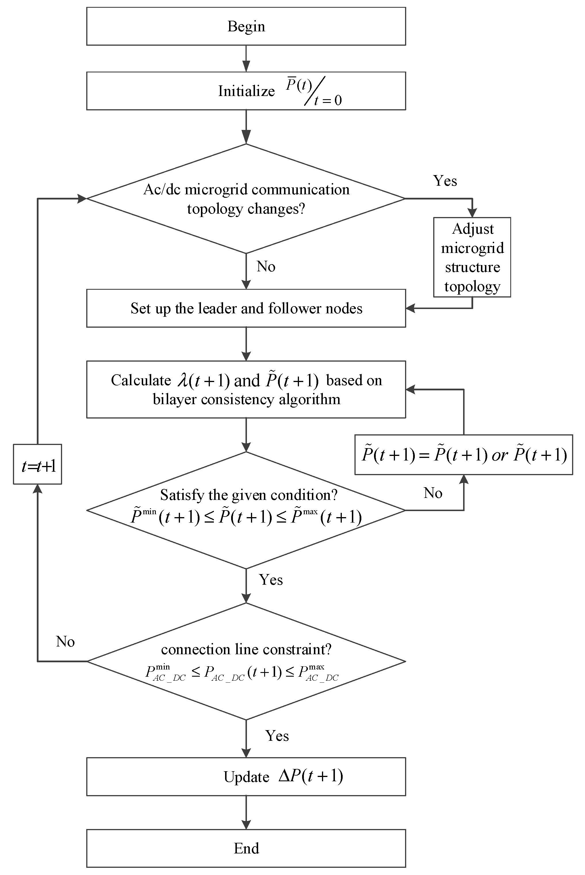
4.2. Algorithm Design with Considering Constraints

When considering the active output of the generator, the update equation of the generator node can be expressed as
{ P T G , i ( t ) = P T G , i min ( t ) ,        P T G , i min ( t ) > P T G , i ( t ) P T G , i ( t ) = λ T G , i ( t ) b T G , i 2 a T G , i , P T G , i min ( t ) P T G , i ( t ) P T G , i max ( t ) P T G , i ( t ) = P T G , i max ( t ) ,        P T G , i ( t ) > P T G , i max ( t )
When considering the power output climbing constraint, the generator node needs to make the following adjustments
{ P T G , i ( t ) = λ T G , i ( t ) b T G , i 2 a T G , i , Δ P T G , i d P T G , i ( t ) P T G , i ( t 1 ) Δ P T G , i u P T G , i ( t ) = P T G , i ( t ) ,     Δ P T G , i d > P T G , i ( t ) P T G , i ( t 1 )     o r P T G , i ( t ) P T G , i ( t 1 ) > Δ P T G , i u
When considering the operating constraints and SOC constraints of the energy storage unit, the output power update equation can be expressed as
{ P B S , i ( t ) = P _ B S , i , P _ B S , i > P B S , i ( t ) & S O C B S , r min S O C B S , r ( t ) S O C B S , r max P B S , i ( t ) = λ B S , i ( t ) b B S , i 2 a B S , i ,     P _ B S , i P B S , i ( t ) P ¯ B S , i & S O C B S , r min S O C B S , r ( t ) S O C B S , r max P B S , i ( t ) = P ¯ B S , i , P B S , i ( t ) > P ¯ B S , i & S O C B S , r min S O C B S , r ( t ) S O C B S , r max P B S , i ( t ) = 0 , S O C B S , r min > S O C B S , r ( t ) S O C B S , r ( t ) > S O C B S , r max
The update equation of the wind generator node with output constraint of wind power is
{ P W T , i ( t ) = 0 ,       0 > P W T , i ( t ) P W T , i ( t ) = λ W T , i ( t ) b W T , i 2 a W T , i , 0 P W T , i ( t ) P W T , i s t ( t ) P W T , i ( t ) = P W T , i s t ( t ) ,    P W T , i ( t ) > P W T , i s t ( t )
The update equation of the PV node with output constraint of photovoltaic power is
{ P S L , i ( t ) = 0 ,       0 > P S L , i ( t ) P S L , i ( t ) = λ S L , i ( t ) b S L , i 2 a S L , i , 0 P S L , i ( t ) P S L , i s t ( t ) P S L , i ( t ) = P S L , i s t ( t ) ,     P S L , i ( t ) > P S L , i s t ( t )
When considering the AC/DC connection line constraint, the update equation for the DC-side power deviation is
{ Δ P D C ( t ) = P A C _ D C min ,               P A C _ D C min > P A C _ D C ( t ) Δ P D C ( t ) = s S D C D M P D C D M , s ( t ) k S S L P S L , k ( t )      r S B S P B S , r ( t ) P A C D C ( t ) , P A C _ D C min P A C _ D C ( t ) P A C _ D C max Δ P D C ( t ) = P A C _ D C max ,               P A C _ D C ( t ) > P A C _ D C max
When considering the AC/DC connection line constraint, the update equation for the AC-side power deviation is
{ Δ P A C ( t ) = P A C _ D C min ,               P A C _ D C min > P A C _ D C ( t ) Δ P A C ( t ) = s S A C D M P A C D M , s ( t ) i S T G P T G , i ( t )        j S W T P W T , j ( t ) + P A C D C ( t ) , P A C _ D C min P A C _ D C ( t ) P A C _ D C max Δ P A C ( t ) = P A C _ D C max ,               P A C _ D C ( t ) > P A C _ D C max
By combining Equations (32)–(38) with (27), for the hybrid microgrid, the two-layer consensus algorithm is developed with constraints, which can be used to effectively solve the hierarchical ED problems of the considered hybrid microgrid. It is worth pointing out that, in the hierarchical framework, the generator nodes of the leadership layer and the tracking layer are obtained. For the leadership layer nodes, they can share the feedback data to those adjacent nodes, and for the tracking nodes, they can receive data from the interconnected leader nodes; finally, the microgrid can achieve the consensus state.
For convenience of understanding, the flow chart of the proposed two-layer consensus algorithm is shown in Figure 2.
Remark 1.
It should be pointed out that for the considered hybrid microgrid, a fully distributed hierarchical algorithm based on combining Equations (32)–(38) with (27) is proposed for solving the ED problem, where the necessary constraints for distributed units are also considered, which could be helpful for ED of the considered microgrid. Compared with the existing consensus method-based approaches [39,40], the proposed hierarchical consensus algorithm has a better adaptability. In addition, in some cases where the ED issue has the hierarchical property, the results in References [39,40] would fail in solving this problem.
Remark 2.
The main difference between this paper and the existing results [39,40,42] is that the hierarchical control thought is utilized in this paper. By the use hierarchical processing, the whole control strategy is divided into two parts, that is, the leadership layer control and the tracking layer control. In our proposed hierarchical consensus strategy, the leadership layer is taken as the upper level, and correspondingly, the tracking layer is taken as the lower level, thus the proposed algorithm could be processed in a hierarchical way, which is in line with the published results. With more leader nodes existing simultaneously, the convergence speed could be faster, and the simulation curves are smoother and more satisfactory.

5. Case Study

In this paper, without loss of generality, the scheduling time for the considered hybrid microgrid is set as 24 h, and the dispatch period is set as 1 h. In a single period, the load demand is taken as the constant. Before explaining the simulation results, some parameters that were used are illustrated in Table 1.
Furthermore, the power generation cost and some operating parameters for the power supply are shown in Table 2 [44].

5.1. Single-Period Simulation Analysis

In the single-period simulation, we verified the proposed algorithm by choosing the data in the time range of 11:00–12:00 in Table 1. The leader nodes are 1, 2, 3, and 5, and the tracking layer nodes are 4 and 6. When considering the constraint conditions shown in Table 2, the proposed distributed two-layer consensus algorithm was tested in the circumstances of isolated AC/DC hybrid microgrid, AC sub-grid, and DC sub-grid, respectively.

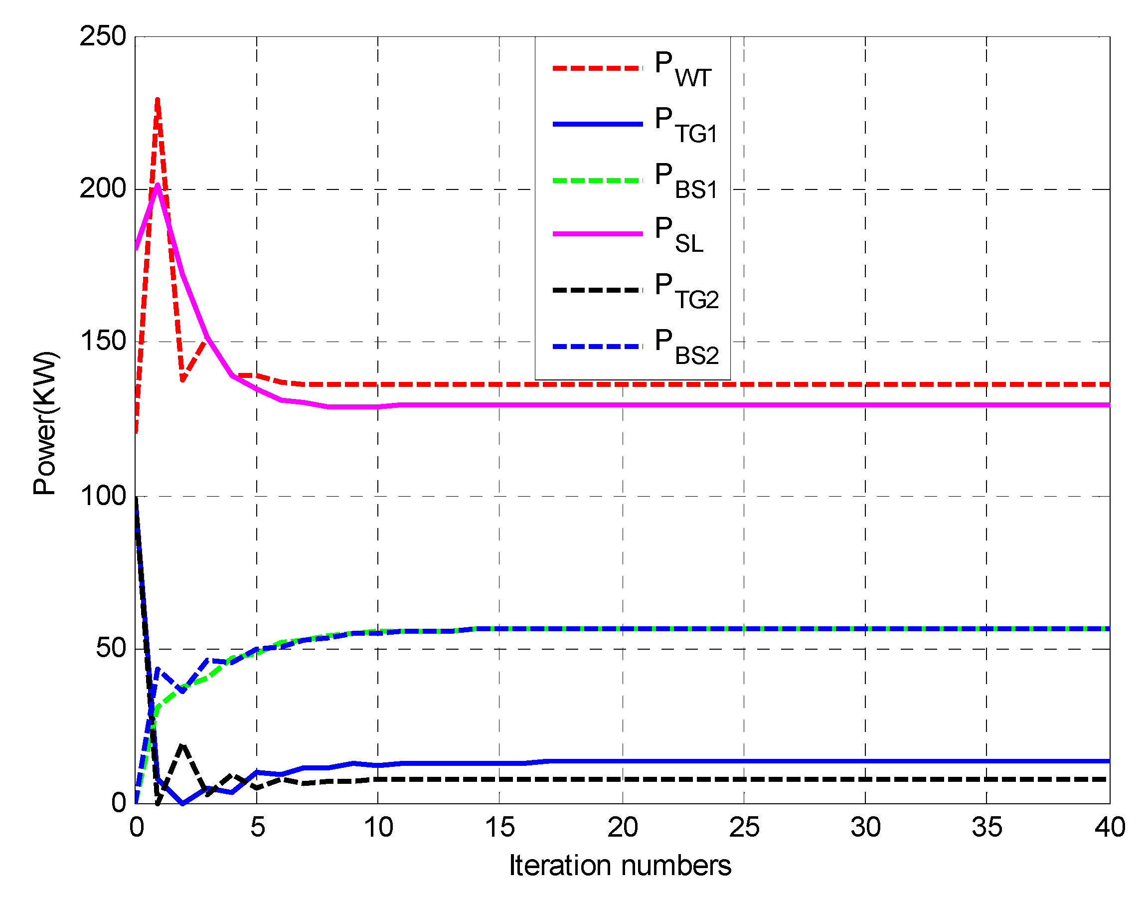
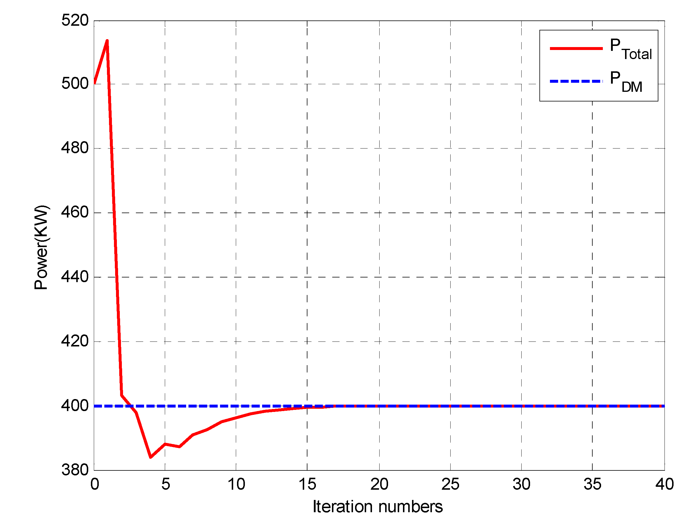
5.1.1. Simulation for AC/DC Hybrid Microgrid

For the isolated AC/DC hybrid microgrid, the simulation results are illustrated in Figure 3 and Figure 4. Figure 3 shows the power output of each node of a single period in the isolated AC/DC hybrid microgrid, which finally converges to 136.18, 13.18, 56.54, 129.85, 7.71 and 56.54 kW, and the output of all nodes operate within the corresponding constraint range. Figure 4 shows the power mismatch of a single period in the hybrid microgrid, where we can find that the power supply meets the load demand at the 20th iteration.
Remark 3.
In the simulation of a single period, the first circumstance we discussed is the AC sub-grid and DC sub-grid, which were investigated as a whole. By calculating the power demand in different sub-grids, the active power balance can be realized by reasonably assigning the power through the tie line. If the active power of the AC sub-grid cannot create self-sufficiency, the missing power will be supplied by the DC sub-grid, and vice versa. The whole active power between the two sub-grids will always keep a dynamic balance, which means the power balance is realized.

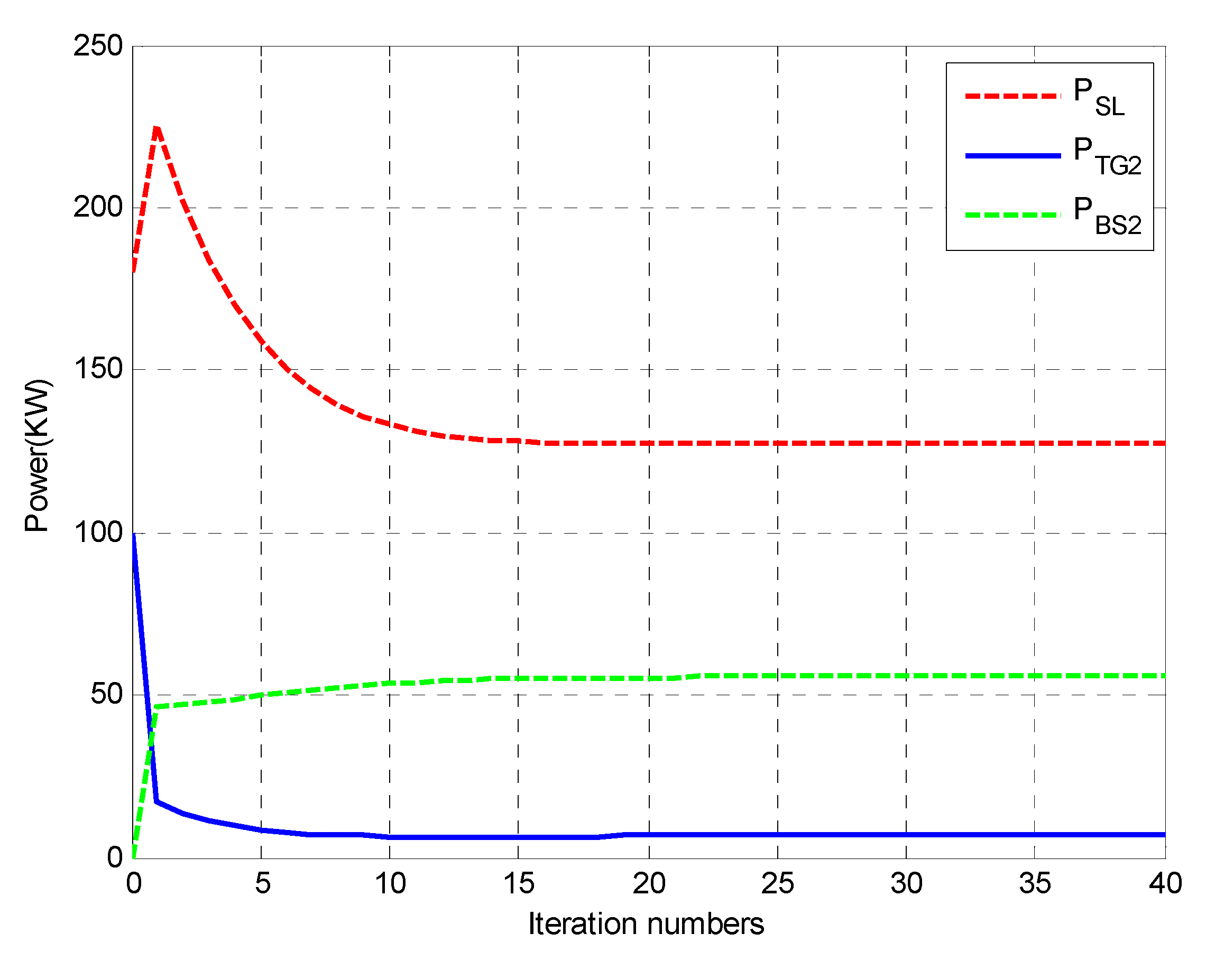
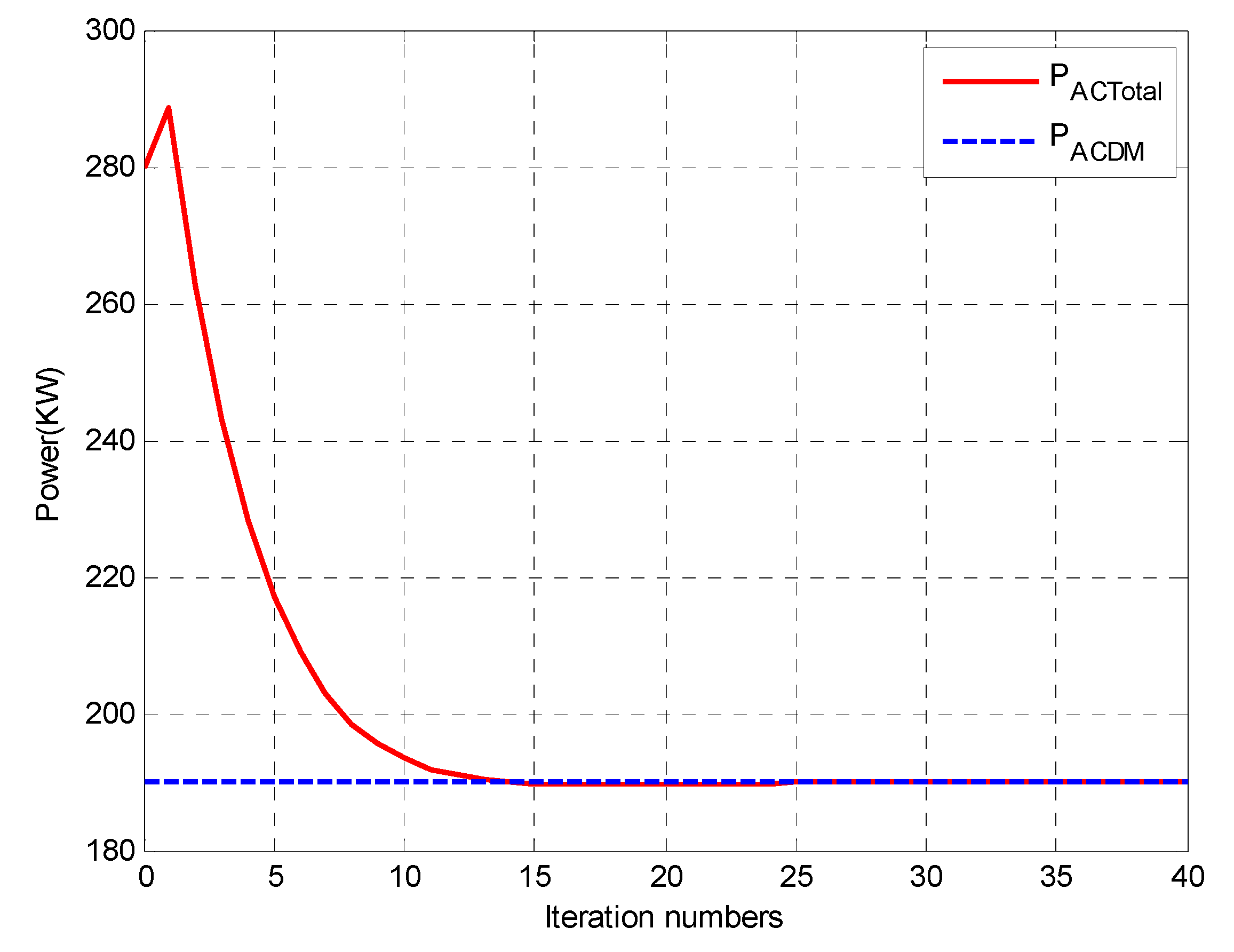
5.1.2. Simulation for AC Sub-Grid

In this case, the wind generator, traditional generator, and energy storage unit are in the AC sub-grid. In the isolated AC/DC hybrid microgrid load from 11:00 to 12:00 shown in Table 1, the load of the AC sub-grid is set as 210 kW. By taking the AC sub-grid as the research object, the simulation results obtained by using the proposed two-layer consensus algorithm are given in Figure 5 and Figure 6. Figure 5 shows the power output of the AC side node of a single period in the AC sub-grid, which finally converges to 138.09, 14.60, and 57.31 kW, respectively. Figure 6 is power mismatch of a single period in the AC sub-grid. We know that the total power output is 210 kW, which can meet the load demand.

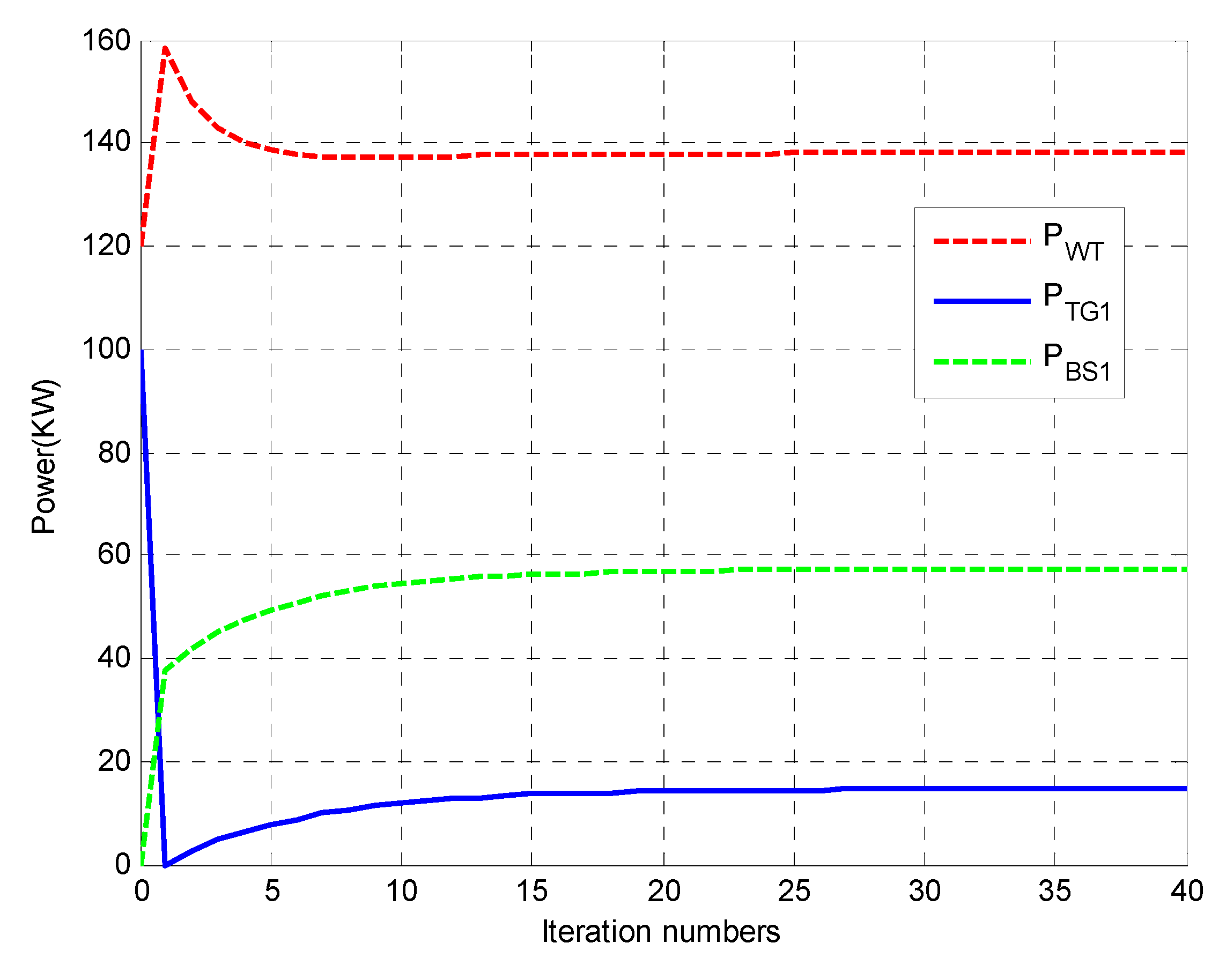
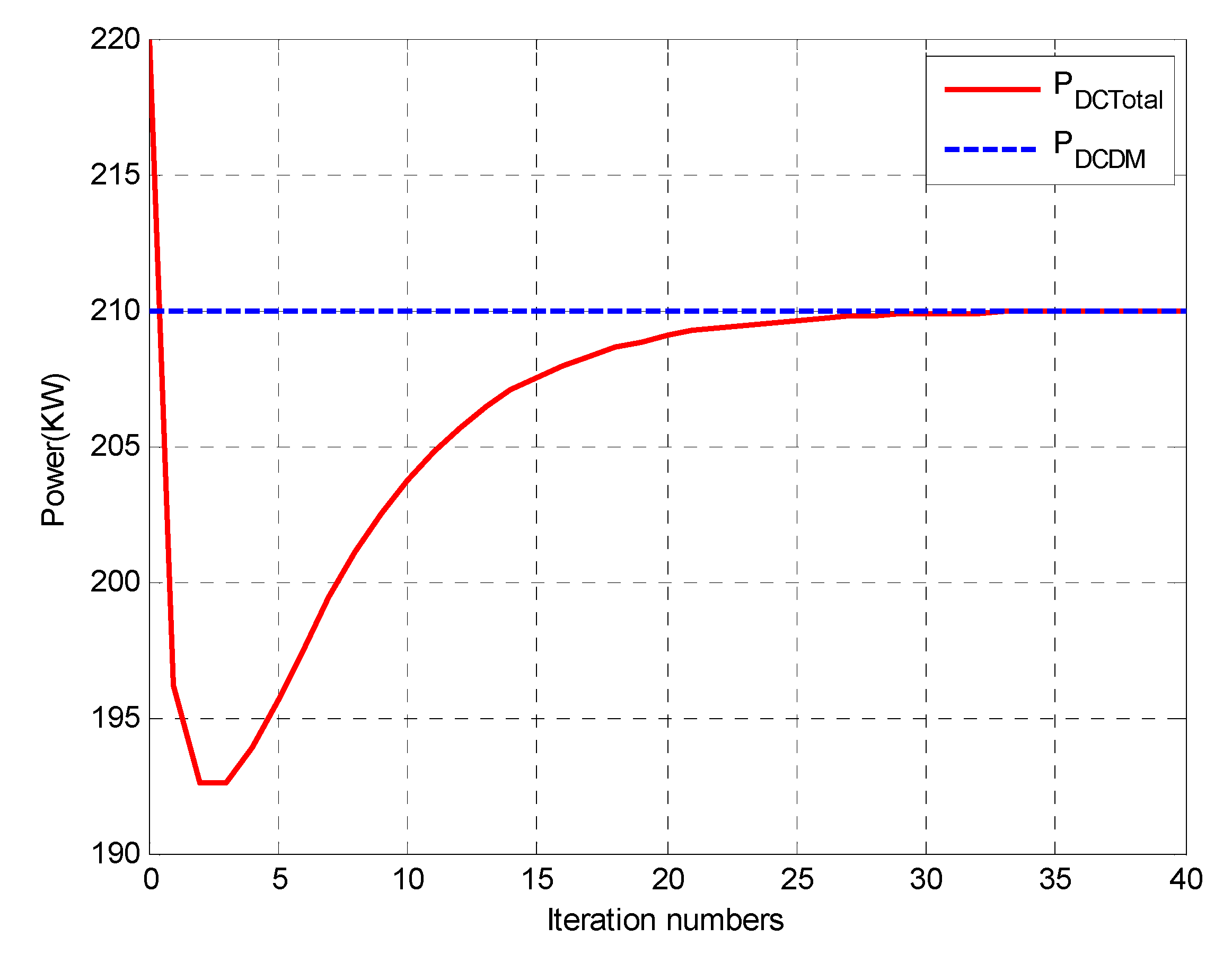
5.1.3. Simulation for DC Sub-Grid

Similarly, three parts of distributed power supply, for instance, photovoltaic power generation, traditional generator, and energy storage unit, are in the DC sub-grid. In the single-period simulation process, the load of the DC sub-grid is taken as 190 kW, and the simulation by using the proposed two-layer consensus algorithm is presented in Figure 7 and Figure 8. Figure 7 is the power output of the DC side node of a single period in the DC sub-grid, which finally converges to 127.70, 6.70, and 55.60 kW respectively, and the sum is 190 kW. Figure 8 is a power mismatch of a single period in the DC sub-grid.
Remark 4.
The second and third circumstances of a single period investigate the power mismatch of the AC sub-grid and the DC sub-grid, respectively. In the AC sub-grid, the power first needs to realize self-sufficiency. That is to say, the total power output of PWT and PTG1 must meet the total loads in this section. The redundant power can be reserved in the energy storage units, or the energy storage units release power to supply the power demand of the AC sub-grid. It is a similar criteria to the DC sub-grid.

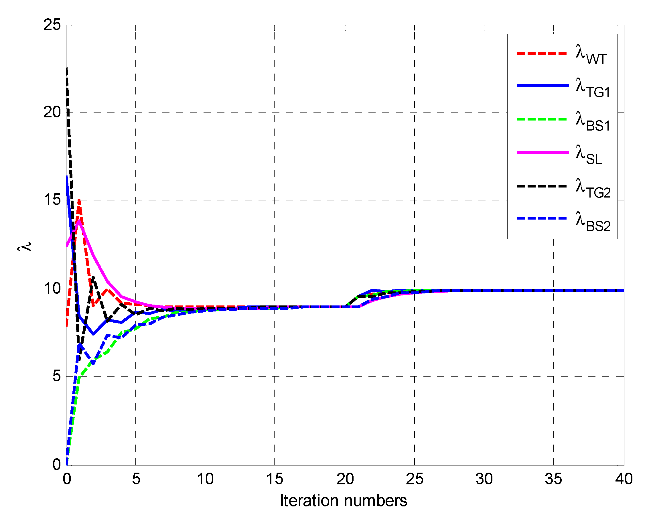
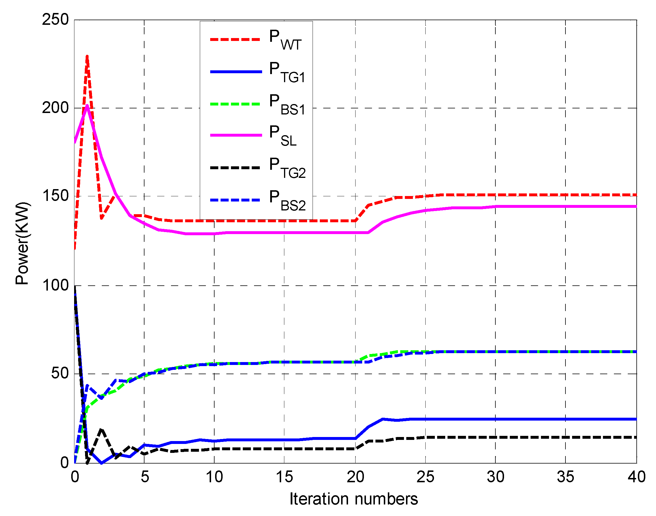
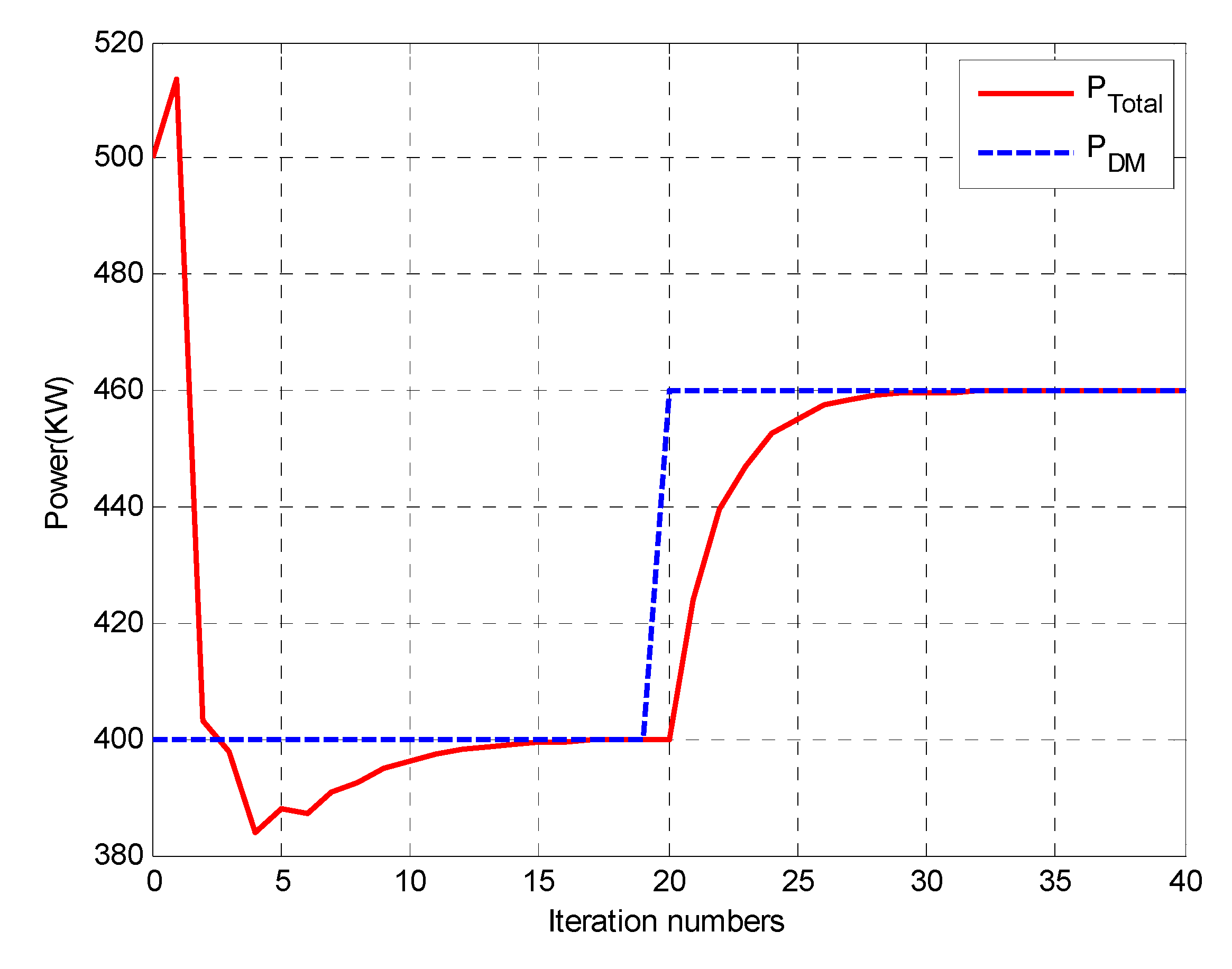
5.2. Multi-Period Simulation Analysis

For further verifying the robustness of the proposed two-layer consensus algorithm, we further added a time period from 12:00 to 13:00 to illustrate the effectiveness. In the multi-period, the load is changed from 400 to 460 kW, and the AC/DC hybrid network is taken as the research object. Figure 9, Figure 10 and Figure 11 illustrate the corresponding simulation results, respectively.
The IC update of each node of the multi-period is presented in Figure 9. Before the 20th iteration, the simulation results are the same as those of Figure 3, in the 20th and subsequent iterations, the nodes are abruptly changed due to the load, the IC also changes accordingly, and finally converges to 9.9196. Figure 10 shows the power output of each node of the multi-period. After the load is abrupt, then the output of each node changes accordingly, and finally converges to 151.21, 24.65, 62.78, 144.18, 14.40, and 62.78 kW, respectively. The sum is 460 kW, which just meets the load demand. Figure 11 is the power mismatch of the multi-period in the hybrid microgrid, following which we can find that at each time period, the total power output meets the total load demand.

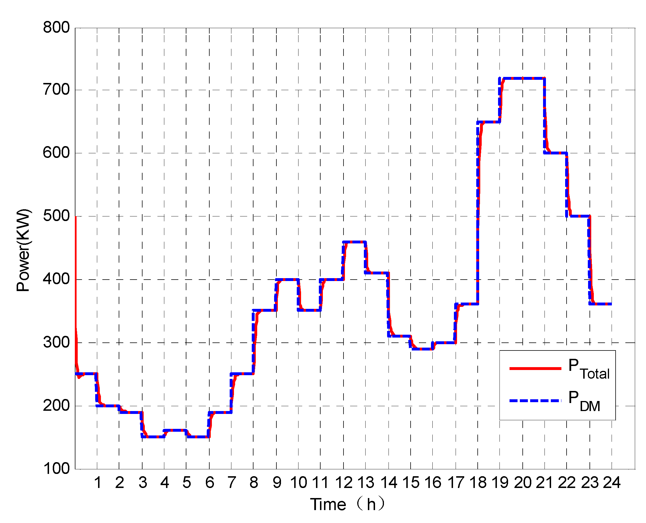
5.3. Full Time-Period Simulation Analysis

The proposed two-layer consensus strategy was further verified in a full time period (24 h). By using the data from Table 1 and Table 2, the simulation results obtained by the developed two-layer consensus method are provided in Figure 12. From this figure, we know that regardless of the time period, the power output can satisfy the total load demand, so we can conclude that the proposed algorithm has better robustness and adaptability.
In the same conditions, by using the methods developed in References [30,31], they can all realize the power balance in a short time. However, due to the fact that no nodes were hierarchically controlled in the mentioned results, the interaction times were longer, and the fluctuations were larger, thus we can conclude that the proposed hierarchical consensus algorithm could be much more effective and satisfactory.
Remark 5.
In the circumstances of a multi-period simulation and a full time-period simulation, two or more time periods were considered to verify the proposed algorithm. Although there exists a time span, the power balance in the AC/DC hybrid microgrid can also be realized. It should be noted that at the moment of time varying between the two time spans, the total load power will mutate to another value, and as time goes by, the new power demand can be satisfied by the output power of the generator, PV, and WT. Finally, the total active power reaches the dynamic balance at each time-steady state.

5.4. Comparison with the Existing Results

In order to verify the robustness and adaptability of the proposed algorithm, some comparison analyses will be given.

5.4.1. Comparison results

In this section, the proposed consensus algorithm will be compared with Reference [42]. Without loss of generality, the parameter values of a and b use the ones in Reference [42] and we chose the time period 12:00–13:00 as an example. From Table 1, we can see that in this period, the load demand is 460 kW. By using the proposed method, the simulation results are shown in Figure 13 and Figure 14.
It can be seen from Figure 13 and Figure 14 that after about the 60th iteration, the power demand can be satisfied by the output power of the generators, and compared with Reference [42], the proposed method can quickly reach convergence and a smooth transition curve. Besides, each node operates within its constraint condition.

5.4.2. Comparison with Different Parameters

In this section, the proposed method will be tested with the parameters shown in Table 2. The time period we chose is also 12:00–13:00. The simulation results are given by Figure 15 and Figure 16.
Compared with Figure 13 and Figure 14, the results in Figure 15 and Figure 16 show better convergence performance, which means that the parameters of a and b can affect the iteration numbers, but cannot change the convergence performance. Thus, the proposed algorithm has a better robustness and adaptation.

6. Conclusions

In this paper, the ED problem of the isolated AC/DC hybrid microgrid was investigated based on the distributed hierarchical consensus method. By using the proposed algorithm, the active power dispatch of the AC/DC microgrid can be realized in a distributed way. Besides, the AC sub-grid and the DC sub-grid can also realize the dynamic power balance in respective sections. If the active power in the AC sub-grid or the DC sub-grid is out of balance, the energy storage units will absorb/release relevant power to ensure the power balance by their charging/discharging process. Finally, some case studies were listed to illustrate the effectiveness of the proposed method, and some comparisons and analyses with the existing results were also provided to verify the robustness and adaptation of the proposed algorithm.
The main work in this paper is realizing the ED problem of the AC/DC hybrid microgrid, which emphatically contains active power dispatch of the AC/DC hybrid microgrid and does not relate to the reactive power dispatch and fault conditions. In future work, the reactive power dispatch problem and the fault conditions of the AC/DC hybrid microgrid will be investigated.

Author Contributions

K.J. developed the concept, conceived the experiments, designed the study, and wrote the original manuscript; K.J. and L.S. performed the experiments and evaluated the data; F.W., L.S., and K.L. reviewed and edited the manuscript. All authors have read and agreed to the published version of the manuscript.

Funding

This research was funded by the National Science Foundation of China (51422701), the Innovation Team of Six Talent Peaks Project of Jiangsu Province (2019-TD-XNY-001), China ‘111’ project of “Renewable Energy and Smart Grid” (B14022).

Conflicts of Interest

The authors declare no conflict of interest.

References

  1. Hatziargyriou, N.; Asano, H.; Iravani, R.; Marnay, C. Microgrids. IEEE Power Energy Mag. 2007, 5, 78–94. [Google Scholar] [CrossRef]
  2. Sao, C.K.; Lehn, W. Control and power management of converter fed microgrids. IEEE Trans. Power Syst. 2008, 23, 1088–1098. [Google Scholar] [CrossRef]
  3. Akinyele, D.; Belikov, J.; Levron, Y. Challenges of microgrids in remote communities: A steep model application. Energies 2018, 11, 432. [Google Scholar] [CrossRef] [Green Version]
  4. Mohamed, S.; Shaaban, M.F.; Ismail, M.; Serpedin, E.; Qaraqe, K.A. An efficient planning algorithm for hybrid remote microgrids. IEEE Trans. Sustain. Energy 2019, 10, 257–267. [Google Scholar] [CrossRef]
  5. Wang, C.; Wu, Z.; Li, P. Research on key technologies of microgrid. Trans. China Electrotech. Soc. 2014, 29, 1–12. [Google Scholar]
  6. Hooshyar, A.; Iravani, R. Microgird protection. Proc. IEEE 2017, 105, 1332–1353. [Google Scholar] [CrossRef]
  7. Yazdanian, M.; Mehrizi-Sani, A. Distributed control techniques in microgrids. IEEE Trans. Smart Grid 2014, 5, 2901–2909. [Google Scholar] [CrossRef]
  8. Song, Y.; Guo, F.; Wen, C. Distributed Control and Optimization Technologies in Smart Grid Systems; CRC Press: Boca Raton, FL, USA, 2017. [Google Scholar]
  9. Xu, Y.; Li, Z. Distributed optimal resource management based on the consensus algorithm in a microgrid. IEEE Trans. Power Electron. 2015, 62, 2584–2592. [Google Scholar] [CrossRef]
  10. Persis, C.D.; Weitenberg, E.R.; Dörfler, F. A power consensus algorithm for DC microgrids. Automatica 2018, 89, 364–375. [Google Scholar]
  11. Meng, L.; Zhao, X.; Tang, F.; Savaghebi, M.; Dragicevic, T.; Vasquez, J.C.; Guerrero, J.M. Distributed voltage unbalance compensation in islanded microgrids by using a dynamic consensus algorithm. IEEE Trans. Power Electron. 2016, 31, 827–838. [Google Scholar] [CrossRef] [Green Version]
  12. Schiffer, J.; Seel, T.; Raisch, J.; Sezi, T. Voltage stability and reactive power sharing in inverter-based microgrids with consensus-based distributed voltage control. IEEE Trans. Control Syst. Technol. 2016, 24, 96–109. [Google Scholar] [CrossRef] [Green Version]
  13. Meng, L.; Dragicevic, T.; Roldán-Pérez, J.; Vasquez, J.C.; Guerrero, J.M. Modeling and sensitivity study of consensus algorithm-based distributed hierarchical control for DC microgrids. IEEE Trans. Smart Grid 2016, 7, 1504–1515. [Google Scholar] [CrossRef] [Green Version]
  14. Bidram, A.; Davoudi, A. Hierarchical structure of microgrids control system. IEEE Trans. Smart Grid 2012, 3, 1963–1976. [Google Scholar] [CrossRef]
  15. Shafiee, Q. Robust networked control scheme for distributed secondary control of islanded microgrids. IEEE Trans. Ind. Electron. 2014, 61, 5363–5374. [Google Scholar] [CrossRef] [Green Version]
  16. Bidram, A.; Davoudi, A.; Lewis, F.L.; Guerrero, J.M. Distributed cooperative secondary control of microgrids using feedback linearization. IEEE Trans. Power Syst. 2013, 28, 3462–3470. [Google Scholar] [CrossRef] [Green Version]
  17. Zhang, G.; Li, C.; Qi, D.; Xin, H. Distributed estimation and secondary control of autonomous microgrid. IEEE Trans. Power Syst. 2017, 32, 989–998. [Google Scholar] [CrossRef]
  18. Chen, G.; Feng, E. Distributed secondary control and optimal power sharing in microgrids. IEEE/CAA J. Autom. Sin. 2015, 2, 304–312. [Google Scholar]
  19. Liu, X.; Wang, P.; Loh, P. A hybrid AC/DC microgrid and its coordination control. IEEE Trans. Smart Grid 2011, 2, 278–286. [Google Scholar]
  20. Navarro-Rodríguez, Á.; García, P.; Georgious, R.; García, J. Adaptive active power sharing techniques for DC and AC voltage control in a hybrid DC/AC microgrid. IEEE Trans. Ind. Appl. 2019, 55, 1106–1116. [Google Scholar] [CrossRef] [Green Version]
  21. Eajal, A.; Yazdavar, A.; El-Saadany, E.; Ponnambalam, K. On the loadability and voltage stability of islanded AC-DC hybrid microgrids during contingencies. IEEE Syst. J. 2019, 13, 4248–4259. [Google Scholar] [CrossRef]
  22. Nejabatkhah, F.; Li, Y. Overview of power management strategies of hybrid AC/DC microgrid. IEEE Trans. Power Electron. 2015, 30, 7072–70789. [Google Scholar] [CrossRef]
  23. Eghtedarpour, N.; Farjah, E. Power control and management in a hybrid AC/DC microgrid. IEEE Trans. Smart Grid 2014, 5, 1494–1505. [Google Scholar] [CrossRef]
  24. Xia, Y.; Wei, W.; Yu, M.; Wang, X.; Peng, Y. Power management for a hybrid AC/DC microgrid with multiple subgrids. IEEE Trans. Power Electron. 2018, 33, 3520–3533. [Google Scholar] [CrossRef]
  25. Zhou, J.; Zhang, H.; Sun, Q.; Ma, D.; Huang, B. Event-based distributed active power sharing control for interconnected AC and DC microgrids. IEEE Trans. Smart Grid 2018, 9, 6815–6828. [Google Scholar] [CrossRef]
  26. Yoo, H.Y.; Nguyen, T.T.; Kim, H.M. Consensus-based distributed coordination control of hybrid AC/DC microgrids. IEEE Trans. Sustain. Energy 2020, 11, 629–638. [Google Scholar] [CrossRef]
  27. Melath, G.; Rangarajan, S.; Agarwal, V. A novel control scheme for enhancing the transient performance of an islanded hybrid AC-DC microgrid. IEEE Trans. Power Electron. 2019, 34, 9644–9654. [Google Scholar] [CrossRef]
  28. Li, X.; Guo, L.; Li, Y.; Guo, Z.; Hong, C.; Zhang, Y.; Wang, C. A unified control for the DC-AC interlinking converters in hybrid AC/DC microgrids. IEEE Trans. Smart Grid 2018, 9, 6540–6553. [Google Scholar] [CrossRef]
  29. Rousis, A.; Konstantelos, L.; Strbac, G. A planning model for a hybrid AC-DC microgrid using a novel GA/AC OPF algorithm. IEEE Trans. Power Syst. 2020, 35, 227–237. [Google Scholar] [CrossRef] [Green Version]
  30. Aprlia, E.; Meng, K.; Hosani, M.; Zeineldin, H.; Dong, Z. Unified power flow algorithm for standalone AC/DC hybrid microgrids. IEEE Trans. Smart Grid 2019, 10, 639–649. [Google Scholar] [CrossRef]
  31. Zhang, Z.; Chow, M. Convergence analysis of the incremental cost consensus algorithm under different communication network topologies in a smart grid. IEEE Trans. Power Syst. 2013, 27, 1761–1768. [Google Scholar] [CrossRef]
  32. Zhao, C.; He, J.; Cheng, P.; Chen, J. Analysis of consensus-based distributed economic dispatch under stealthy attacks. IEEE Trans. Ind. Electron. 2018, 64, 5107–5117. [Google Scholar] [CrossRef]
  33. Hamdi, M.; Chaoui, M.; Idoumghar, L.; Kachouri, A. Coordinated consensus for smart grid economic environmental power dispatch with dynamic communication network. IET Gener. Transm. Distrib. 2018, 12, 2603–2613. [Google Scholar] [CrossRef]
  34. Yang, S.; Tan, S.; Xu, J. Consensus based approach for economic dispatch problem in a smart grid. IEEE Trans. Power Syst. 2013, 28, 4416–4426. [Google Scholar] [CrossRef]
  35. Tang, Z.; Hill, D.H.; Liu, T. A novel consensus-based economic dispatch for microgrids. IEEE Trans. Smart Grid 2018, 9, 3920–3922. [Google Scholar] [CrossRef]
  36. Wang, R.; Li, Q.; Zhang, B.; Wang, L. Distributed consensus based algorithm for economic dispatch in a microgrid. IEEE Trans. Smart Grid 2019, 10, 3630–3640. [Google Scholar] [CrossRef]
  37. Chen, G.; Zhao, Z. Delay effects on consensus-based distributed economic dispatch algorithm in microgrid. IEEE Trans. Power Syst. 2018, 33, 602–612. [Google Scholar] [CrossRef]
  38. Lv, Z.; Wu, Z.; Dou, X.; Zhou, M.; Hu, W. Distributed economic dispatch scheme for droop-based autonomous DC microgrid. Energies 2020, 13, 404. [Google Scholar] [CrossRef] [Green Version]
  39. He, H.; Han, B.; Xu, C.; Zhang, L.; Li, G.; Wang, K. Optimal management system of hybrid AC/DC microgrid based on consensus protocols. Electr. Power Autom. Equip. 2018, 38, 138–146. [Google Scholar]
  40. Lin, P.; Jin, C.; Xiao, J.; Li, X.; Shi, D.; Tang, Y.; Wang, P. A distributed control architecture for global system economic operation in autonomous hybrid AC/DC microgrids. IEEE Trans. Smart Grid 2019, 10, 2603–2617. [Google Scholar] [CrossRef]
  41. Jiang, K.; Wu, K.; Zong, X. Dynamic economic dispatch of AC/DC microgrid based on finite-step consensus algorithm. In Proceedings of the 2019 IEEE Sustainable Power and Energy Conference (iSPEC), Beijing, China, 21–23 November 2019; pp. 1909–1914. [Google Scholar]
  42. Jiang, K.; Wu, F.; Zong, X.; Shi, L.; Lin, K. Distributed dynamic economic dispatch of an isolated AC/DC hybrid microgrid based on a finite-step consensus algorithm. Energies 2019, 12, 4637. [Google Scholar] [CrossRef] [Green Version]
  43. Zhang, W.; Xu, Y.; Liu, W.; Zang, C.; Yu, H. Distributed online optimal energy management for smart grids. IEEE Trans. Ind. Informat. 2015, 11, 717–727. [Google Scholar] [CrossRef]
  44. Wood, A.; Wollenberg, B. Power Generation, Operation, and Control; John Wiley & Sons: New York, NY, USA, 1996. [Google Scholar]
Figure 1. The structure of the considered AC/DC hybrid microgrid.
Energies 13 03209 g001
Figure 2. Flow chart of the dynamic economic dispatch (ED) strategy based on the two-layer consensus algorithm.
Energies 13 03209 g002
Figure 3. Power output of each node of a single period in the AC/DC hybrid microgrid.
Energies 13 03209 g003
Figure 4. Power mismatch of a single period in the AC/DC hybrid microgrid.
Energies 13 03209 g004
Figure 5. Power output of the AC side node of a single period in the AC sub-grid.
Energies 13 03209 g005
Figure 6. Power mismatch of a single period in the AC sub-grid.
Energies 13 03209 g006
Figure 7. Power output of the DC side node of a single period in the DC sub-grid.
Energies 13 03209 g007
Figure 8. Power mismatch of a single period in the DC sub-grid.
Energies 13 03209 g008
Figure 9. IC update of each node of the multi-period in the AC/DC hybrid microgrid.
Energies 13 03209 g009
Figure 10. Power output of each node of the multi-period in the AC/DC hybrid microgrid.
Energies 13 03209 g010
Figure 11. Power mismatch of the multi-period in the AC/DC hybrid microgrid.
Energies 13 03209 g011
Figure 12. Power mismatch of the full time period (24 h) in the AC/DC hybrid microgrid.
Energies 13 03209 g012
Figure 13. Power output of the proposed method with the same parameters.
Energies 13 03209 g013
Figure 14. Power mismatch of the proposed method with the same parameters.
Energies 13 03209 g014
Figure 15. Power output of the proposed method with different parameters.
Energies 13 03209 g015
Figure 16. Power output of the proposed method with different parameters.
Energies 13 03209 g016
Table 1. Daily load, wind generator output and photovoltaic (PV) output.
No.Time PeriodLoad/kWPV/kWWind Generator/kW
100:00–01:00250083
201:00–02:00200065
302:00–03:00190084
403:00–04:00150062
504:00–05:001600138
605:00–06:00150059
706:00–07:0019015143
807:00–08:002503589
908:00–09:003509554
1009:00–10:0040013084
1110:00–11:00350150123
1211:00–12:00400180120
1312:00–3:00460170104
1413:00–14:00410150118
1514:00–15:00310120139
1615:00–16:002909555
1716:00–17:003007080
1817:00–18:003605054
1918:00–19:006501069
2019:00–20:007200122
2120:00–21:007200122
2221:00–22:006000137
2322:00–23:005000108
2423:00–24:00360057
Table 2. Microgrid system operating parameters.
No.Node a i b i c i [ P i min , P i max ] ( kW )
1WT0.03287.75220[0, 300]
2TG10.04307.80208[0, 500]
3BS10.07907.62172[−100, 100]
4PV0.03447.84352[0, 300]
5TG30.07367.80178[0, 500]
6BS20.07907.70175[−100, 100]

