Abstract
Inter-cell interference has been identified as one of the major challenges of multiple-input–multiple-output (MIMO)-enabled cellular systems. This problem occurs when the same pilot sets are reused across adjacent cells to save bandwidth for data transmission. As a result, so-called pilot contamination occurs, which cannot be mitigated with an increased number of serving antennas. In this work, we proposed a partial pilot allocation scheme (PPA) to tackle the pilot contamination problem and consequently improve the uplink throughput of users in multi-cell massive MIMO systems. This was achieved by using the large-scale characteristics of the fading channel to keep users with a weak channel condition out of the effect of severe interference during the pilot allocation process. Simulation results showed that the proposed scheme outperformed both smart pilot allocation (SPA) and conventional schemes. In particular, PPA improved the uplink rate by 30% compared to the SPA—a recently proposed schema. Furthermore, our simulation results clearly showed that PPA improved the cumulative distribution function (CDF) of the signal-to-interference-plus-noise ratio (SINR) and uplink throughput.
1. Introduction
Massive multiple-input–multiple-output (MIMO) systems are one of the promising technologies that have conceived to meet the continuous increase in demand for high-speed data in future fifth generation (5G) wireless networks [1]. In this system, a large number of antennas is associated with a base station (BS) and multiple users are served simultaneously. Although the channel response is random, the effective channel between the BS and the desired user becomes almost deterministic (i.e., the effect of small-scale fading is reduced). As the number of antennas is large, this property (known as channel hardening) is achieved by applying coherent combining/precoding. Moreover, the channel vector for any two users is asymptotically orthogonal because of the favorable propagation property in massive MIMO systems. This enables BS to easily relieve interference between such users, thereby making the use of linear combining and precoding sufficient [2]. Thus, these properties enhance energy efficiency and increase the spectral efficiency of the wireless network [3,4,5,6].
As multiple antennas are equipped with BS, it is preferable for massive MIMO systems to operate in time division duplex (TDD) mode [7,8]. In TDD-massive MIMO systems, the overhead signals needed for channel state information (CSI) are limited. In other words, TDD greatly saves network bandwidth as it allows CSI only in one direction (i.e., uplink) because of the channel reciprocity property. Unlike TDD, the frequency division duplex (FDD) mode needs CSI on both sides (i.e., uplink and downlink) which consumes a large amount of bandwidth.
In multi-cell massive MIMO systems [9] which operate according to a synchronous TDD mode, the channel coherence block has a limited size; therefore, the number of orthogonal pilot sequences is insufficient for all users. To solve this issue, the orthogonal pilot sequences have to be reused by each cell. Despite this significant step forward, the channel estimation error is increased by the inter-cell interference from users who share the same pilot sequence [1,10]. Thus, the channel estimations of two users who use the same pilot sequence are correlated. This problem is known as pilot contamination, and its severity depends on the correlation degree between the channel estimations of any two users sharing the same pilot sequence [2]. Figure 1 depicts the impact of pilot contamination at the target cell in a multi-cell massive MIMO system, as all users share the same pilot sequence.
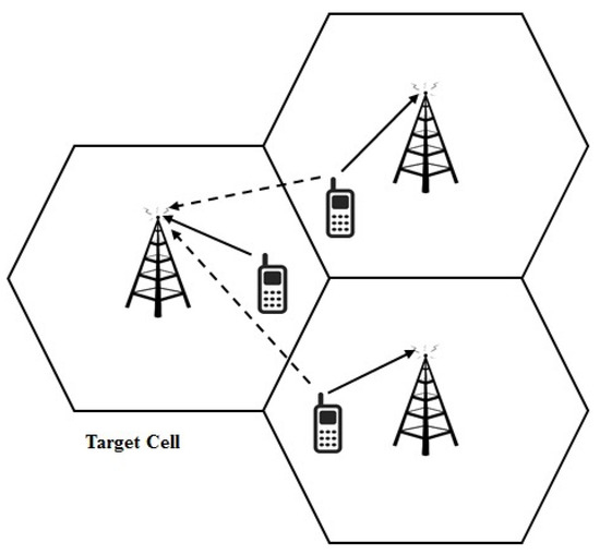
Figure 1.
The impact of pilot contamination at the target cell in a multi-cell massive multiple-input–multiple-output (MIMO) system, as all users share the same pilot signal.
Another problem which can be considered to be akin to the pilot contamination is the so-called pilot spoofing attack [11,12,13]. As with pilot contamination, the uplink pilot signals are polluted by other signals, which in turn cause channel estimation error at the BS side. However, in the pilot spoofing attack, the uplink pilot signal is intentionally polluted by an identical signal in order to eavesdrop in the downlink data phase. Thus, a physical layer of security might be needed to address this issue to prevent information leakage.
One of the several techniques which have been proposed to mitigate or relieve the effects of pilot contamination is pilot allocation. In this work, we propose a scheme that uses large-scale fading coefficients to assign pilot sequences for specific users while others are randomly assigned their pilot sequences. The proposed scheme greatly reduces the effects of interfering users that cause a high level of interference within a typical cell of a multi-cell massive MIMO system. It also improves the throughput of users that are largely affected by intense pilot contamination because of their poor channel quality. Since the performance of these users can be affected easily by imperfections at the BS side, a fully digital transceiver architecture is utilized.
The remainder of this paper is organized as follows: related work is presented in Section 2, the system architecture is described in Section 3 and the pilot contamination issue is illustrated in Section 4. Section 5 shows the achieved uplink rate. The proposed PPA scheme is detailed in Section 6 and the performance evaluation is demonstrated in Section 7. Section 8 concludes this article.
2. Related Work
Several techniques have been proposed to tackle the pilot contamination issue by using pilot allocation methods. Depending on users’ location, a line of sight (LOS) interference expression is derived in [14]. The pilot allocation process was implemented according to LOS expression. Although the spectral efficiency of the system was improved by this scheme, it requires a longer time to implement the assignment process, especially in large networks. In [15], the angular region of the targeted user, which largely depends on its location, was determined. In order to mitigate the pilot contamination, this region should be kept interference-free during the pilot allocation process. However, the implementation of this scheme introduced high computational complexity because of the developed joint optimization problem.
The relation between pilot allocation and user distribution has been exploited to alleviate pilot contamination in [16]. This is achieved by using a deep-learning (DL) algorithm for pilot allocation. Despite this scheme almost achieving the same performance as the exhaustive search algorithm (ESA), the DL algorithm requires large amounts of data and subsequently requires a longer time for data processing. The authors in [17] proposed a vertex graph-coloring-based pilot assignment scheme to mitigate the inter-cell interference (ICI) between cellular users. Based on the angle of arrival (AoA) correlation and distances between users, they constructed an ICI graph, which was considered during pilot allocation. However, the evaluation of the ICI graph requires second-order channel information.
A new pilot assignment scheme based on hierarchical pilot reuse was proposed in [18]. In the work, different groups of pilot sequences were used in the neighbor cells where the number of these pilot groups increased as the effect of pilot contamination became severe. These groups of pilot sequences were obtained according to the tree division principle as a large number of pilot groups meant a greater distance between cells that used the same pilot group. However, this approach improved the system throughput when the ratio of the channel coherence time to the number of users in each cell was relatively large.
For the purpose of relieving the effect of pilot contamination, the fairness between users was improved in [19]. The scheme was based on the harmonic SINR utility function for pilot allocation. Even though an enhancement was achieved in terms of fairness, a higher complexity is associated with this scheme in large networks. In [20], the optimal pilot sequences were allocated to users who exhibited the worst performance degradation, which was evaluated according to the value of the uplink rate. Although this method yielded better performance, it became ineffective when the channel condition was bad. The authors in [21] focused on maximizing the capacity of the whole system by enhancing the performance of the users with a low SINR. This was implemented by firstly allocating the pilot sequences to users with a weak channel condition; however, the complexity increased in large-scale networks. A smart pilot allocation (SPA) scheme was proposed in [22] to enhance the performance of users greatly affected by pilot contamination. The pilot sequences which resulted in low interference were assigned to users with bad channel quality; however, the interference experienced by these users was very high because the inter-cell interference was not taken into consideration, which limited the performance of SPA. The impact of the outgoing inter-cell interference was considered in our previous work [23]. Even though an improvement in system throughput was recorded, this caused a relatively high complexity associated with the pilot assignment process.
Unlike the previous works in [16,19,21], the proposed PPA scheme has a lower computational complexity and can be deployed for use in large-scale networks. Factors such as LOS interference, user location and AoA, used in [14,15,17], were not considered for pilot allocation in this work. This is because these factors are difficult to estimate. On the other hand, the large-scale fading coefficients used in our approach are almost invariant within the coherence interval and therefore can be estimated easily. In addition, compared to [20,22], the effect of the outgoing interference has been effectively managed in this work, which efficiently reduces the pilot contamination.
In this work, we propose a PPA scheme which uses the large-scale fading coefficients to allocate pilot sequences for specific users while others are randomly assigned their pilot sequences. The contributions of this work are summarized as follows:
- We define a threshold value to determine the interfering users that cause severe interference at the target cell;
- We formulate an optimization problem for pilot allocation and propose a heuristic algorithm that solves this problem by maximizing the uplink throughput of users with poor channel quality;
- The performance of the proposed PPA scheme is evaluated in terms of the signal-to-interference-plus-noise ratio (SINR) and the uplink rate. The results are compared with other schemes.
3. System Architecture
In this model, a TDD-massive MIMO system with L cells is considered. The BS in each cell is equipped with M ≫ one antenna, and K users with a single antenna are served simultaneously by the corresponding BS assuming that antenna-to-user ratio M/K > 1 [2]. All cells are assumed to have the same radius and the same number of users. The channel vector that links the k-th user in the j-th cell to the BS in the i-th cell is modeled as shown below:
where denotes the small-scale fading vector with a complex Gaussian distribution of zero mean and unity variance, (IM), and denotes the large-scale fading coefficient, which models the path-loss and the shadowing between the user k in the j-th cell and the BS in the i-th cell. The large distance between the users and the BS makes the space between antenna elements negligible; therefore, all antenna elements have the same large-scale fading coefficient.
4. Pilot Contamination
In the TDD protocol, each coherence block consists of time-frequency complex samples. These samples are divided into three phases as follows: samples are used for the pilot phase, samples are dedicated for the uplink data phase, and the last samples are reserved for the downlink data phase. In the pilot phase, the BSs receive the uplink pilot signals from users who are subject to their coverage area. These signals are used for channel response estimation between users and the corresponding BSs, which is implemented at the latter. The uplink data phase is allocated for users to send their data to the serving BSs, while the data transmission is reversed in the downlink data phase. The BSs take advantage of information regarding the channel’s response to detect the received signals, which are transmitted from users during the uplink data phase. On the other hand, this channel response is also used to precode the downlink signals in order to beam-form such signals towards the intended users in the downlink data phase. Moreover, the channel information of the interfering users is helpful for interference suppression throughout data transmission [2]. Figure 2 illustrates the coherence block in the TDD protocol.
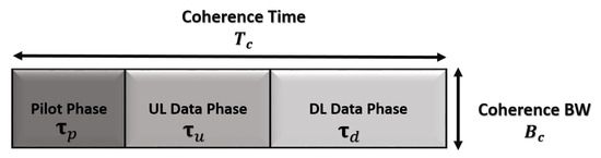
Figure 2.
The coherence block in the time division duplex (TDD) protocol, where complex-valued samples.
In a multi-cell massive MIMO system which operates in the TDD mode, the time-frequency samples limit the number of pilot sequences. These sequences are mutually orthogonal (i.e., ) and extend over samples, but are inadequate for all users. The insufficiency in the number of pilot sequences can be solved by reusing these sequences in all adjacent cells; however, this causes channel estimation errors within a target cell. This is due to the inter-cell interference effect from users that use the same pilot sequences (i.e., pilot contamination).
The uplink received pilot signal at the BS i during the pilot phase can be written as
where denotes the uplink transmission power for the pilot signal, which is assumed equal for all users. denotes the received additive white Gaussian noise (AWGN) assuming that independent and identically distributed (i.i.d) random variables have zero mean and a variance of . The above equation can be rewritten again to show the pilot contamination term as follows:
where the pilot contamination is represented by the second term, while the first term represents the received pilot signals for all users in the target cell i. Throughout this work, the minimum mean square error (MMSE) is considered for the channel estimation. Therefore, the estimated channel vector, , is described as follows [2]:
and
where , which denotes the spatial correlation matrix of the estimated channel, is the inverse of the normalized correlation matrix and is the received proceed signal, .
5. Achieved Uplink Rate under the Pilot Contamination Effect
In the uplink data transmission phase, all users in multi-cell massive MIMO systems send the uplink data to their corresponding BS; thus, the received signal at the BS in cell i is expressed as
where represents the power of the uplink-transmitted symbol. denotes the uplink-transmitted symbol of the k-th user in the j-th BS, where = 1, and denotes the AWGN vector which has zero mean and a variance of .
In order to decode the uplink-received signal, a linear receiver combination is used for signal detection. Throughout this paper, maximum ratio combining (MRC) and zero forcing (ZF) linear detectors are used at the receiver. These received linear detectors are given as follows [24]:
Thus, the decoded symbol of the k-th user, located in cell i, can be represented at the i-th BS as follows:
where and denote the k-th column of the matrices and , respectively. To clearly describe the effect of pilot contamination, the above equation can be rewritten as following:
The impact of pilot contamination is described by the third term in the above expression, while the first part describes the desired symbol. The second term describes the intra-cell interference effect; finally, the last term is the uncorrelated noise.
Accordingly, the average uplink SINR of the user in cell is
where represents the effect of intra-cell interference and uncorrelated noise. The unlimited increase in antennas, with which BS is equipped, greatly reduces the effect of [10], and the averaged uplink SINR in (10) is described by the large-scale fading coefficients as follows:
The above expression was derived in [10] according to the random matrix theory in [25]. The ergodic achievable uplink rate per user k in bit/ channel use is calculated by [26] as
where refers to the uplink transmission period. It can be observed from (12) that the pilot contamination affects the system throughput even if extra antenna elements are added to the BS or the transmitted power of the pilot and uplink data is increased.
6. Proposed Scheme
In this section, the optimization problem for pilot allocation is formulated. Then, a heuristic algorithm to solve the optimization problem is explained in detail.
6.1. Problem Formulation
The performance of multi-cell massive MIMO systems is highly affected by pilot contamination, which is a result of the reuse of the same pilot sequences in all adjacent cells. This issue arises when the channel condition between users and their corresponding BS is weak and becomes more severe in the presence of high inter-cell interference from the adjacent cells. The pilot allocation method can efficiently address this issue. However, the number of iterations during the allocation process is very high and depends mainly on the number of users.
In the SPA scheme [22], which has low computational complexity, the allocation of the pilot sequences depends on their associated interference and the users’ channel condition. The set of pilot sequences associated with high interference are avoided for users with a weak channel condition. Although low-interference pilot sequences are assigned to users with poor channel quality, the associated interference is still high compared to their channel quality. Therefore, the outgoing inter-cell interference should be kept low at the target BS i. To achieve this, the SINR is formulated as the following optimization problem:
where refers to the users which suffer from poor channel quality in the target cell. Next, we present the details of our proposed algorithm to solve the above problem.
6.2. Partial Pilot Allocation (PPA)
PPA focuses on improving the performance of the users that degrade the system performance. These users have poor channel quality and are concurrently exposed to severe interference from users in adjacent cells. The aim of PPA is to shield these users from the effect of the high outgoing inter-cell interference by keeping the channel cross-gain of interfering users low compared to the channel quality of the target cell users. To implement this, large-scale fading coefficients are needed; the method used to find these will be explained at the end of this section.
In order to solve the optimization problem in (13) to improve the SINR of users with poor channel quality, we define some parameters to illustrate the proposed scheme. The squared channel quality for the target cell users is represented by
whereas the severity of interference from users located in the adjacent cells is described by the squared channel cross-gain as
In this work, the users which cause the highest interference within a target cell will be considered. Therefore, the adjacent cells’ users can be classified according to the squared channel cross-gain as
where denotes the k-th user in the j-th adjacent cell that causes high inter-cell-interference, denotes the user that causes low inter-cell interference and denotes the threshold value, which can be defined as follows:
It is obvious that the threshold value depends only on the squared channel quality of the user with the worst channel quality in the target cell. This threshold value ensures that the users with poor channel quality are shielded from the effect of severe interference. Therefore, users who cause severe interference (i.e., ) are considered in the pilot assignment process because of their high impact on the targeted BS, while other interfering users , classified as low-interfering users, are assigned the pilot sequences randomly.
The target cell users which have good channel quality (i.e., high ) will share the same pilot sequences as the adjacent cells’ users , in which denotes the interfering users that are allocated the same pilot sequence:
where and refer to the number of users and users in each cell, respectively. The value of may not be equal in all adjacent cells. Other users of the target cell who have poor channel quality will be assigned their pilot sequences randomly.
The following Algorithm 1 explains the allocation process.
The squared channel cross-gain () of the interfering users is used to measure the interference severity at the target BS; the method of finding will be explained later. The adjacent cells’ users , who produce high interference at the target BS , are first determined according to (14). Thus, the pilot allocation process is limited to users.
The PPA algorithm distributes these users into () groups subject to the following restrictions:
- Only one user from each adjacent cell belongs to the same group. In other words, L-1 users are involved in each group ;
- The users which have similar orders of interference severity are grouped together. For instance, the users that generate the highest interference are labeled by . This group includes the worst-interfering users from all adjacent cells, while the last group contains those that cause the lowest interference (considering only users) at the targeted BS.
| Algorithm 1 Partial Pilot Allocation (PPA). |
| 1: : |
| 2: |
| 3: Output: |
| 4: Allocating pilot sequences for all users in all cells |
| 5: Procedure: |
| 6: Evaluate . |
| 7: Finding According to (15). |
| for each adjacent cells do |
| for all users in cell j do |
| 8: Evaluate: , |
| 9: Determining users According to (14). |
| end for |
| end for |
| 10: Classifying users into different groups: , = [ ] |
| 11: Assign the pilot sequence to the users in . |
| 12: Remaining users (i.e., ) are randomly allocated their pilot sequences. |
| 13: Users with high (in the target cell) are sharing the pilot sequence of users. |
| 14: Remaining users, in the target cell, are allocated their pilot sequences randomly. |
After grouping the users, the pilot allocation process will be implemented at the group level, where () out of pilot sequences are allocated to the groups. In each group, the allocated pilot sequence is reused by all interfering users that belong to that group. Consequently, different levels of interference severity are caused by the () pilot sequences. The highest level is caused by the first pilot sequence, which is allocated to the worst-interfering users (i.e., users). The interference resulting from the remaining pilot sequences is definitely lower and gradually decreases until the last pilot sequence, which is shared by users.
The remaining users, which generate a low level of interference, are allocated their pilot sequences randomly.
In the PPA scheme, the pilot sequences are mutually orthogonal within each cell. For instance, if there are users in the same cell generating a high level of interference at the target cell, they will be allocated orthogonal pilot sequences. This condition is also maintained for users, who are randomly assigned their pilot sequences.
In the target cell i, the users with a good channel condition share the same pilot sequence as users. In other words, the pilot sequences that are associated with severe interference are allocated to high-channel-quality users in a descending way, where the highest interference pilot sequence is allocated to a user who has the best channel quality, and this process continues with all (K-) users. Thus, the effects of these pilot sequences are deemed weak when they are used by the users with a good channel condition. The pilot sequences, which are associated with low interference, are distributed randomly to the remaining users (with a poor channel quality). Therefore, these users are barely affected by the associated interference.
The authors in [27,28] assume that the statistical channel covariance can be obtained precisely. To implement the proposed PPA scheme, only the large-scale fading coefficients are required. These coefficients do not change frequently during the coherence interval and are easy to track with low complexity [1,29,30]. In long-term evolution advanced (LTE-A) systems, information regarding the channel conditions for the available BSs can be provided at the serving BS, which is explained as follows. Initially, each user keeps monitoring the available BSs (by measuring their channel conditions) to decide the best BS for the handover. The channel conditions of users with the serving BS and neighbor BSs are available at the serving BS, where the latter condition is obtained by sending the neighbor list messages from the users to their serving BS (to obtain the channel’s cross-gain with the neighbor BSs). The channel condition information should be available for all BSs to implement the PPA scheme; thus, to allow information sharing among the network BSs, a coordinated multi-point (CoMP) unit is implemented in LTE-A. In addition, BSs are connected to the mobility management entity (MME) via the S1 interface, which has a huge computing ability; therefore, the large-scale fading coefficients can be collected from the BSs in the cellular network with the aid of MME, which facilitates the implementation of the proposed algorithm [30,31]. This means that the channel cross-gain of the interfering users becomes available at the serving BS, including the channel gain (channel quality) of the serving cell users which already exist.
The PPA scheme has low computational complexity in comparison with some of the state-of-the-art proposals, such as those presented in [16,19,21]. Depending on the threshold value, some users will be allocated their pilot sequences randomly. Thus, the incurred computational complexity is O (, where denotes the number of users in the adjacent cells with and . denotes the target cell users which are allocated their pilot sequence, . This means that this scheme requires less implementation time as compared to that achieved in prior research. For instance, the works in [19,21] incur O (K3) and O (L2), respectively; these require more computational time than this PPA scheme. Additionally, the scheme in [16] incurs O (), which is obviously higher than our proposed PPA scheme. Since the SPA scheme only considers the serving cell, it incurs O ().
7. Performance Evaluation
The Monte Carlo simulation is used to implement the proposed scheme, while the base code for the MATLAB simulation is obtained from [26]. A hexagonal cellular system is considered with L cells, and each BS is equipped with M antenna elements assuming K users with a single antenna are available in each cell [1,10]. The target cell (i.e., the center cell) is surrounded by adjacent cells. Table 1 summarizes the system parameters used in the simulation. The large-scale fading coefficient which represents the effect of path-loss and shadowing is modeled as follows [2]:
where [km] defines the distance between the k-th user in the j-th cell and the BS in the i-th cell and is the path-loss exponent. determines the median channel gain at a reference distance of 1 km, which can be calculated according to several propagation models [32], and is the shadow fading, which creates a log-normal random variation around the nominal value ).

Table 1.
The values of the simulation parameters. BS: base station; SNR: signal-to-noise ratio.
The PPA scheme is evaluated against both conventional [1,10,33] and SPA schemes. In order to analyze the proposed scheme, two scenarios were used. In the first scenario, we applied specific setting parameters for Figure 3, Figure 4, Figure 5, Figure 6, Figure 7, Figure 8, Figure 9, Figure 10, Figure 11 and Figure 12, while in the second scenario, different values were applied for Figure 13.
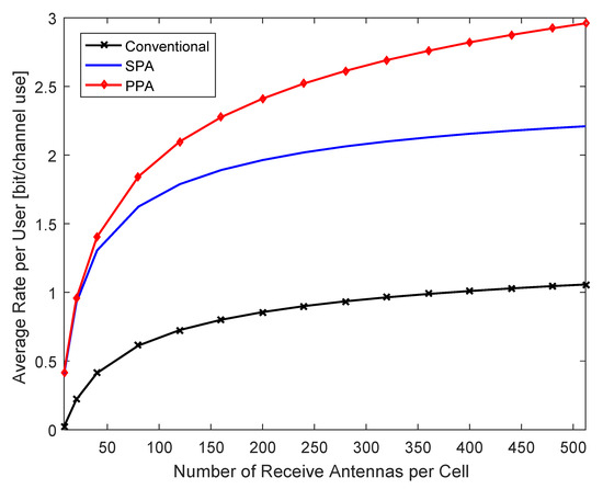
Figure 3.
Average uplink rate per user for various numbers of antenna elements using a zero forcing (ZF) detector.
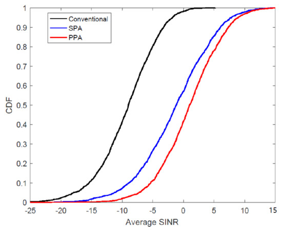
Figure 4.
Cumulative distribution function (CDF) of the average signal-to-interference-plus-noise ratio (SINR) per user when M = 64 using a ZF detector.
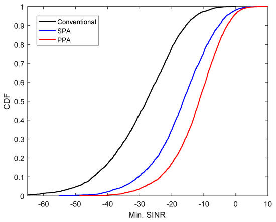
Figure 5.
CDF of the minimum SINR per user when M = 64 using a ZF detector.
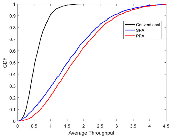
Figure 6.
CDF of the average uplink rate per user when M = 64 using a ZF detector.
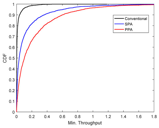
Figure 7.
CDF of the minimum uplink rate per user when M = 64 using a ZF detector.
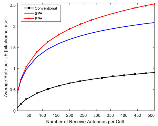
Figure 8.
Average uplink rate per user for various numbers of antenna elements using a maximum ratio combining (MRC) detector.
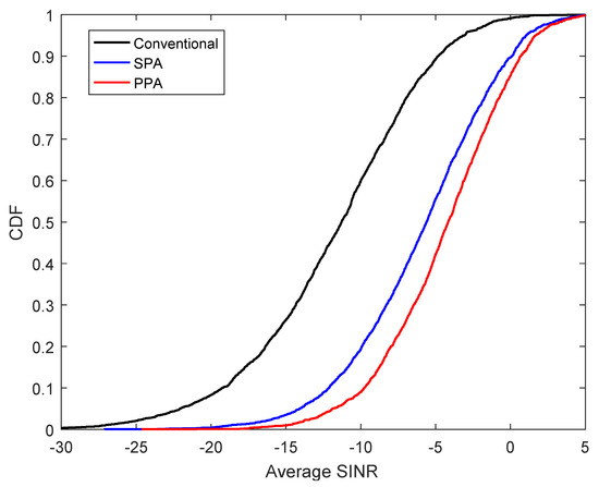
Figure 9.
CDF of the average SINR per user when M = 64 using an MRC detector.
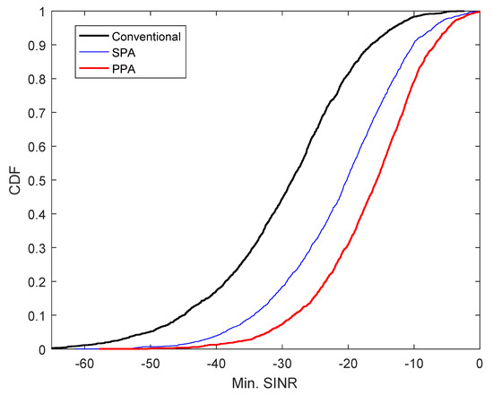
Figure 10.
CDF of the minimum SINR per user when M=64 using an MRC detector.
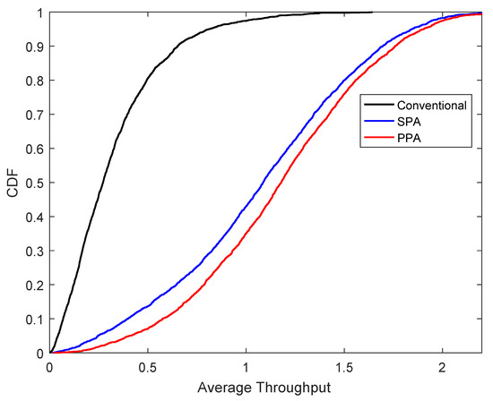
Figure 11.
CDF of the average uplink rate per user when M = 64 using an MRC detector.
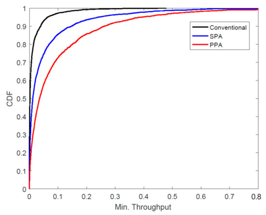
Figure 12.
CDF of the minimum uplink rate per user when M = 64 using an MRC detector.
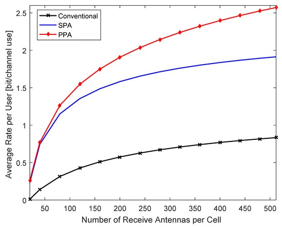
Figure 13.
Average SINR per user for various number of antenna elements using ZF, assuming severe interference.
We first consider the performance of the PPA scheme by using a ZF linear detector. The average uplink rate against the number of antennas for PPA, SPA and other conventional schemes is shown in Figure 3. It is clear that the PPA outperforms the other schemes, especially when the number of antenna increases. Moreover, the improvement in throughput obtained by the PPA scheme can be observed at small values of M. This improvement occurs because it efficiently reduces the effect of interference from the adjacent cells by considering the users that were exposed to a high interference level at the target cell.
Figure 4 and Figure 5 depict the cumulative distribution function (CDF) of the average and the minimum SINR, respectively, when the number of antenna is 64. Obviously, the PPA scheme achieves the best performance compared to the other schemes. The improvements in the CDF of the minimum SINR for the PPA scheme are reflected on the CDF of the average SINR. This means the performances of the users, which were highly affected by pilot contamination, have improved. This is because the pilot sequences that cause intense interference at the target cell are not reused by users with poor channel quality, which significantly enhances their SINR.
In Figure 6 and Figure 7, the performance of the PPA scheme is compared with SPA and the conventional schemes in terms of the CDF of the uplink rate when M is 64. Figure 6 shows the achieved gain in the CDF of the average uplink rate for the PPA scheme over the compared schemes. For instance, in the PPA scheme, the probability of achieving an uplink rate greater than 2.5 Hz/user is almost 37% (i.e., the highest), while it is approximately 32% and 0% for the SPA and the conventional schemes, respectively. The level of enhancement achieved by the PPA scheme can be observed clearly from the CDF of the minimum uplink rate in Figure 7. For example, the achieved gain in the PPA scheme with the minimum uplink rate is approximately twice the SPA scheme, whereas it is almost 1.32 times greater with an average uplink rate. Allocating the worst pilot sequences to users who have good channel quality will not affect their performance, as the interference is considered low when compared to the channel quality. Additionally, the random allocation of low-interference pilot sequences to the remaining users (with poor channel quality) will have a limited impact on their performance compared to other schemes. As a result, not only does this process enhance the system throughput, but also the pilot allocation process will be implemented more quickly and require less time.
The performance of the PPA scheme is evaluated by using a maximum ratio combining (MRC) linear detector at the receiver. With the MRC detector, the impact of the PPA scheme is compared with SPA and conventional schemes. Figure 8 shows the performance of the PPA scheme in terms of the average uplink rate when the number of antennas is increased. Clearly, the average uplink rate is increased with the PPA scheme when compared to the other schemes. The steady improvement in throughput performance becomes more evident when the number of antennas increases. The PPA scheme exhibits superior performance because the assignment process was implemented while taking the effect of the outgoing interference into account.
The CDF of the SINR for the PPA scheme is shown in Figure 9 and Figure 10. In Figure 9, the PPA scheme achieves the best average SINR in comparison with the SPA and the conventional schemes when M is 64. For example, by using the PPA scheme, the probability of achieving an average SINR over −10 dB is better than that in SPA and conventional schemes by about 10% and 50%, respectively. Meanwhile, this probability increases to approximately 20% and 52% with the minimum SINR in order to achieve an SINR of more than −20 dB, as shown in Figure 10. This improvement in SINR indicates that the level of interference is greatly reduced. This is because it was ensured that the users’ channel quality is larger than the interference associated with the pilot sequences, which was achieved by minimizing the mutual interference between users who share the same pilot sequence.
With the assumption that M = 64, the CDFs of the average and the minimum uplink rate are illustrated in Figure 11 and Figure 12, respectively. As observed from both figures, the PPA scheme outperforms the SPA and the conventional schemes, especially with respect to the minimum uplink rate. The PPA scheme outperforms other schemes since it keeps poor channel quality users out of the effect of the highly interfering users.
The validity of the proposed scheme is shown in Figure 13. The average uplink rate for different numbers of antennas has been calculated assuming severe interference at the given cell. The ZF detector is used at the receiver and the parameters depicting this level of interference are given in Table 1 (scenario 2). It is clear that the proposed scheme still achieves better performance as compared to the other schemes when it is applied to scenarios with higher levels of interference.
8. Conclusions
In this work, an effective pilot allocation scheme has been proposed to tackle the pilot contamination issue in multi-cell massive MIMO systems. A formulated optimization problem was solved to enhance the system throughput in the uplink direction by reducing the effect of inter-cell interference. This was achieved by allocating a part of the pilot sequences to specific users (determined according to a threshold value), while other users were allocated their pilots randomly. Rigorous simulation experiments were carried out, and the obtained results showed that this proposed scheme outperforms the other schemes with different linear receiver detection methods. Moreover, the proposed scheme has been shown to perform effectively in environments that suffer from a high level of interference.
Author Contributions
A.S.A.-h. developed the idea. A.S.A.-h. and N.K.N. formulated the optimization problem and designed the proposed algorithm. N.K.N., A.S., S.S., A.M.M., and S.M.G. contributed to the scientific discussion and critical revision of the paper. All authors have read and agreed to the published version of the manuscript.
Funding
This work was funded by [Advancing the State of the Art of MIMO: The Key to Successful Evolution of Wireless Networks (ATOM)] grant number [690750-ATOM-H2020-MSCA- RISE-2015, UPM: 6388800-10801], and the APC was funded by the [Research Management Centre (RMC)].
Acknowledgments
In this section you can acknowledge any support given which is not covered by the author contribution or funding sections. This may include administrative and technical support, or donations in kind (e.g., materials used for experiments).
Conflicts of Interest
The authors declare no conflicts of interest.
References
- Marzetta, T.L. Noncooperative cellular wireless with unlimited numbers of base station antennas. IEEE Trans. Wirel. Commun. 2010, 9, 3590–3600. [Google Scholar] [CrossRef]
- Björnson, E.; Hoydis, J.; Sanguinetti, L. Massive MIMO Networks: Spectral, Energy, and Hardware Efficiency. Found. Trends Signal Process. 2017, 11, 154–655. [Google Scholar] [CrossRef]
- Lim, Y.G.; Chae, C.B.; Caire, G. Performance Analysis of Massive MIMO for Cell-Boundary Users. IEEE Trans. Wireless Commun. 2015, 14, 6827–6842. [Google Scholar] [CrossRef]
- Larsson, E.G.; Edfors, O.; Tufvesson, F.; Marzetta, T.L. Massive MIMO for Next Generation Wireless Systems. IEEE Commun. Mag. 2014, 52, 186–195. [Google Scholar] [CrossRef]
- Björnson, E.; Larsson, E.G.; Debbah, M. Optimizing Multi-Cell Massive MIMO for Spectral Efficiency: How Many Users Should be Scheduled? Proc. IEEE Global Conf. Signal Inf. Process. 2014. [Google Scholar]
- Rajatheva, N. 5G Mobile and Wireless Communications Technology; Osseiran, A., Monserrat, J.F., Marsch, P., Eds.; Cambridge University Press: Cambridge, UK, 2016; ISBN 978-1-107-13009-8. [Google Scholar]
- Björnson, E.; Larsson, E.G.; Marzetta, T.L. Massive MIMO: Ten Myths and One Critical Question. IEEE Commun. Mag. 2016, 54, 114–123. [Google Scholar] [CrossRef]
- Jose, J.; Ashikhmin, A.; Marzetta, T.; Vishwanath, S. Pilot Contamination and Precoding in Multi-Cell TDD Systems. IEEE Trans. Wirel. Commun. 2011, 10, 2640–2651. [Google Scholar] [CrossRef]
- Yu, W.; Kwon, T.; Chin, C. Multicell Coordination via Joint Scheduling, Beamforming, and Power Spectrum Adaptation. IEEE Trans. Wirel. Commun. 2013, 12, 1–14. [Google Scholar] [CrossRef]
- Rusek, F.; Persson, D.; Lau, B.K.; Larsson, E.G.; Marzetta, T.L.; Edfors, O.; Tufvesson, F. Scaling up MIMO: Opportunities and Challenges with Very Large Arrays. IEEE Signal Process. Mag. 2013, 30, 40–60. [Google Scholar] [CrossRef]
- Darsena, D.; Gelli, G.; Iudice, I.; Verde, F. Design and performance analysis of channel estimators under pilot spoofing attacks in multiple-antenna systems. IEEE Trans. Inf. Forensics Secur. 2020, 15, 3255–3269. [Google Scholar] [CrossRef]
- Xiong, Q.; Liang, Y.; Li, K.; Gong, Y. An Energy-Ratio-Based Approach for Detecting Pilot Spoofing Attack in Multiple-Antenna Systems. IEEE Trans. Inf. Forensics Secur. 2015, 10, 932–940. [Google Scholar] [CrossRef]
- Tugnait, J. Pilot Spoofing Attack Detection and Countermeasure. IEEE Trans. Wirel. Commun. 2018, 66, 2093–2106. [Google Scholar] [CrossRef]
- Akbar, N.; Yan, S.; Yang, N.; Yuan, J. Location-Aware Pilot Allocation in Multicell Multiuser Massive MIMO Networks. IEEE Trans. Veh. Technol. 2018, 67, 7774–7778. [Google Scholar] [CrossRef]
- Muppirisetty, L.S.; Charalambous, T.; Karout, J.; Fodor, G.; Wymeersch, H. Location-Aided Pilot Contamination Avoidance for Massive MIMO Systems. IEEE Trans. Wirel. Commun. 2018, 17, 2662–2674. [Google Scholar] [CrossRef]
- Kim, K.; Lee, J.; Choi, J. Deep Learning Based Pilot Allocation Scheme (DL-PAS) for 5G Massive MIMO System. IEEE Commun. Lett. 2018, 22, 828–831. [Google Scholar] [CrossRef]
- Dao, H.T.; Kim, S. Vertex Graph-Coloring-Based Pilot Assignment with Location-Based Channel Estimation for Massive MIMO Systems. IEEE Access 2018, 6, 4599–4607. [Google Scholar] [CrossRef]
- Sohn, J.; Yoon, S.W.; Moon, J. On Reusing Pilots Among Interfering Cells in Massive MIMO. IEEE Trans. Wirel. Commun. 2017, 16, 8092–8104. [Google Scholar] [CrossRef]
- Ma, S.; Xu, E.L.; Salimi, A.; Cui, S. A Novel Pilot Assignment Scheme in Massive MIMO Networks. IEEE Commun. Lett. 2018, 7, 262–265. [Google Scholar] [CrossRef]
- Wu, Y.; Liu, T.; Cao, M.; Li, L.; Xu, W. Pilot Contamination Reduction in Massive MIMO Systems Based on Pilot Scheduling. URASIP J. Wirel. Commun. Netw. 2018. [Google Scholar] [CrossRef]
- Du, T.; Wang, Y.; Wang, J.; Du, Y.; Yang, L. Multi-Cell Joint Optimization to Mitigate Pilot Contamination for Multi-Cell Massive MIMO Systems. In Proceedings of the 2017 IEEE 85th Vehicular Technology Conference (VTC Spring), Sydney, NSW, Australia, 4–7 June 2017. [Google Scholar] [CrossRef]
- Zhu, X.; Wang, Z.; Dai, L.; Qian, C. Smart Pilot Assignment for Massive MIMO. IEEE Commun. Lett. 2015, 19, 1644–1647. [Google Scholar] [CrossRef]
- Al-hubaishi, A.S.; Noordin, N.K.; Sali, A.; Subramaniam, S.; Mansoor, A.M. An Efficient Pilot Assignment Scheme for Addressing Pilot Contamination in Multicell Massive MIMO Systems. Electronics 2019, 8, 372. [Google Scholar] [CrossRef]
- NGO, H.Q.; Larsson, E.G.; Marzetta, T.L. Energy and Spectral Efficiency of Very Large Multiuser. IEEE Trans. Wirel. Commun. 2013, 61, 1436–1449. [Google Scholar] [CrossRef]
- Cramer, H. Random Variables and Probability Distributions; Cambridge University Press: Cambridge, UK, 2004. [Google Scholar]
- Björnson, E.; Matthaiou, M.; Debbah, M. Massive MIMO with Non-Ideal Arbitrary Arrays: Hardware Scaling Laws and Circuit-Aware Design. IEEE Trans. Wirel. Commun. 2015, 14, 4353–4368. [Google Scholar]
- Li, M.; Jin, S.; Gao, X. Spatial Orthogonality-Based Pilot Reuse for Multi-Cell Massive MIMO Transmission. In Proceedings of the 2013 International Conference on Wireless Communications and Signal Processing, Hangzhou, China, 24–26 October 2013. [Google Scholar]
- Müller, R.; Cottatellucci, L.; Vehkaperä, M. Blind Pilot Decontamination. IEEE J. Sel. Top. Signal Process. 2014, 8. [Google Scholar] [CrossRef]
- Dai, L.; Wang, Z.; Yang, Z. Spectrally Efficient Time-Frequency Training OFDM for Mobile Large-Scale MIMO Systems. IEEE J. Sel. Areas Commun. 2013, 31. [Google Scholar] [CrossRef]
- Sesia, S.; Toufik, I.; Baker, M. Network Architecture and Protocols. In LTE-The UMTS Long Term Evolution: From Theory to Practice; John Wiley & Sons Ltd.: Chichester, UK, 2011; ISBN 978-0-470-66025-6. [Google Scholar]
- Zhu, X.; Dai, L.; Wang, Z. Graph Coloring Based Pilot Allocation to Mitigate Pilot Contamination for Multi-Cell Massive MIMO Systems. IEEE Commun. Lett. 2015, 19, 1842–1845. [Google Scholar] [CrossRef]
- Sarkar, T.K.; Ji, Z.; Kim, K.; Medouri, K.; Salazar-Palma, M. A Survey of Various Propagation Models for Mobile Communication. IEEE Antennas Propag. Mag. 2003, 45, 51–82. [Google Scholar] [CrossRef]
- Fernandes, F.; Ashikhmin, A.; Marzetta, T.L. Inter-Cell Interference in Noncooperative TDD Large Scale Antenna Systems. IEEE J. Sel. Areas Commun. 2013, 31, 192–201. [Google Scholar] [CrossRef]


© 2020 by the authors. Licensee MDPI, Basel, Switzerland. This article is an open access article distributed under the terms and conditions of the Creative Commons Attribution (CC BY) license (http://creativecommons.org/licenses/by/4.0/).