1. Introduction
The constant, increasing demand in energy is moving the world away from traditional power generation and towards a more environmentally sustainable society. This is evident in the continuous effort, over the years, to increase installed wind generation capacity worldwide. For larger wind turbines in mega-watt (MW) range, the doubly fed induction generator (DFIG) is a popular solution due to its controllability via the rotor at slip power rating [
1,
2,
3,
4].
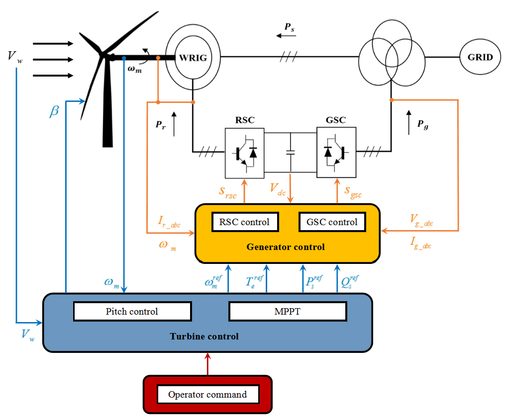
In addition to reduced cost as a direct consequence of the fractionally rated rotor converter, decoupled active and reactive power control on the DFIG can be achieved using the classical vector controller scheme [
5,
6,
7,
8,
9]. A conventional DFIG setup is shown in
Figure 1.
Alternative control strategies have been proposed in various relevant literatures such as direct control [
10,
11,
12], sensorless control [
13] and model predictive control based on non-linear control principles [
14,
15]. However, the classical vector control scheme, based on PI compensators with feed-forward decoupling, is still predominantly used for its relatively reduced complexity. The main challenge in the design of a vector-controlled DFIG is providing the proportional and integral gain values for the PI compensator in order to achieve the desired system response.
Most of the DFIG control strategies proposed, thus far, are subjected to their normal operating condition where the machine stator is already exchanging power with the grid. During the startup period of the wind turbine driven DFIG, excessive stator current transients may result from a mismatch between the stator and grid voltage. Therefore, adopting a smooth grid connection procedure is essential to prevent excessive mechanical and electrical stresses on the machine.
Only a limited number of contributions have dealt with the importance of a smooth DFIG grid connection. The general solution, described in [
16,
17,
18,
19,
20,
21], produces an induced stator voltage equal to the grid voltage by adjusting the rotor current prior to synchronization. This results in a low impact connection to the grid, where current transients are minimal. However, the controller design, to a large extent remains absent—especially with respect to tuning the gains of the PI compensator. DFIG rotor dynamics vary depending on the stator connection with the grid, which gives rise to the need for designing an additional rotor current regulator for open stator conditions. Systematic vector controller designs for DFIG normal and synchronizing operations, with gain parameters derived from pole placement tuning have been provided in [
22,
23]. However, in the related literature, very little insight is provided with respect to the control design criterions, and the DFIG synchronization dynamics during unbalanced grid voltage conditions have not been considered. Another paper [
24] discusses a control design where positive sequence stator voltage directly controls the positive sequence rotor voltages, and negative sequence rotor voltages are being controlled by negative sequence stator voltages by using an auxiliary controller. Hence the outer current control loops are eliminated, and rotor current transients are ignored in favor of overall better control dynamics. Similarly in [
25], direct voltage control is implemented (DVC). Inner current control loop is eliminated for an additional control loop to acquire stator voltages and currents. The paper discusses simulated results, only showing the voltage and frequency synchronization during intermittent wind patterns. Moreover, the rotor current transients are completely ignored in the analysis. In [
26], with the direct power control (DPC), a virtual phase angle is introduced to eliminate the coupling interactions between the phase locked loop and the unbalanced network. To simplify the control, the sequence separation of the components has been removed and the system only operates in a positive sequence reference frame. The controller on the grid side converter is auto-tuned for the negative sequence components which are assumed to be zero throughout the analysis. This is an important issue as DFIG-based wind turbines are usually situated in rural areas where unbalanced grid voltages can be considered a frequently occurring condition. From the statistics given in [
27], symmetrical faults appear 5% compared to asymmetrical faults i.e., in the form single line to ground fault 70%, line-to-line fault 15%, and double line to ground fault 10%.
In this paper, a complete DFIG synchronization procedure is proposed which results in a low impact connection to unbalanced grid voltages. This is achieved with the implementation of a simple dual sequence rotor current controller during DFIG open stator operations. The proposed controller enables the induced stator voltage to become as unbalanced as the grid voltage, hence enabling a smooth connection. The DFIG positive and negative sequence models in their respective synchronous frames are investigated to facilitate the appropriate initial rotor current settings, hence reducing the rotor current transients and the DC voltage ripples. The complete proposed grid synchronization procedure for the DFIG wind turbine has been validated on a 2.2 kW lab-scaled DFIG test bench.
2. Mathematical Modelling of DFIG under Unbalanced Grid Voltage Conditions
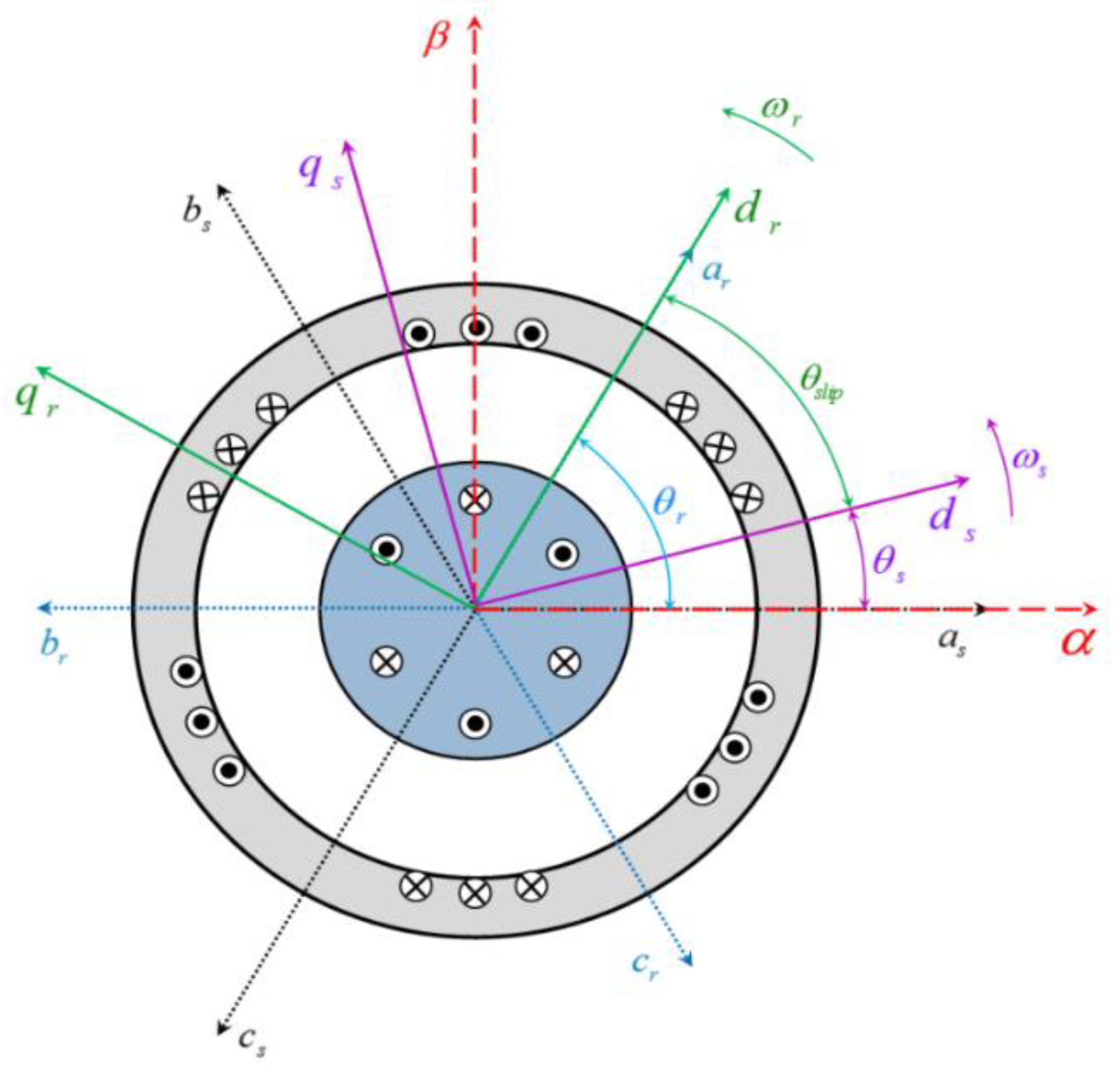
It is well known that DFIG dynamic behavior can be expressed in a synchronously rotating reference frame, with arbitrary angular velocity, using Clarke’s transformation.
Figure 2 presents all the reference frames related to a DFIG where
depicts the synchronous axes.
The electrical dynamics of the DFIG seen from this reference frame are constant during a steady state, allowing the application of well-defined linear control techniques. During unbalanced grid voltage conditions, the DFIG dynamic model should include both positive and negative sequence components of voltage and current. The zero sequence component can be neglected as generally the machines do not have a neutral connection with the grid.
Voltage and current sequence components can be extracted in the stationary
reference frame as:
where
is the generic vector representation of voltages and currents, and the subscripts
and
represent positive and negative sequence components, respectively.
The stationary components expressed in (1) can be transformed to the synchronous
reference frames as:
where
is the grid voltage radian frequency and the superscripts
and
indicate positive and negative sequence reference frames, respectively.
According to (2) and (3), it can be seen that the negative sequence component produces oscillations in the positive sequence reference frame at twice the grid frequency. The same is true when observing the positive sequence component in the negative sequence reference frame. In order to facilitate the control of DFIG positive and negative sequence currents, notch filters tuned at twice the grid frequency should be incorporated to eliminate these oscillations.
The dynamic model of the DFIG electrical circuits in the positive sequence reference frame can thus be expressed as:
where
are the resistances and inductances of the stator and rotor, and
is the magnetizing inductance. The stator and rotor voltages, currents and fluxes are represented as
, respectively. The rotor electrical frequency is expressed as
.
3. Controller for DFIG Normal Operation under Unbalanced Grid Voltages
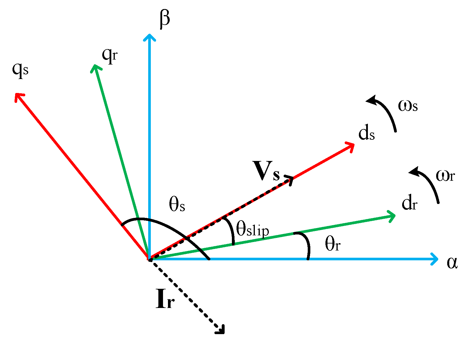
The rotor voltage equations for the DFIG can be derived from (4)–(7) by using the stator flux or voltage orientation for the synchronous reference frame alignment. The stator voltage orientation adopted in this paper is illustrated in
Figure 3.
It can be seen that the positive sequence
axis is aligned with the stator voltage vector
which results in the following positive and negative rotor
equations:
where
is the machine leakage coefficient and
.
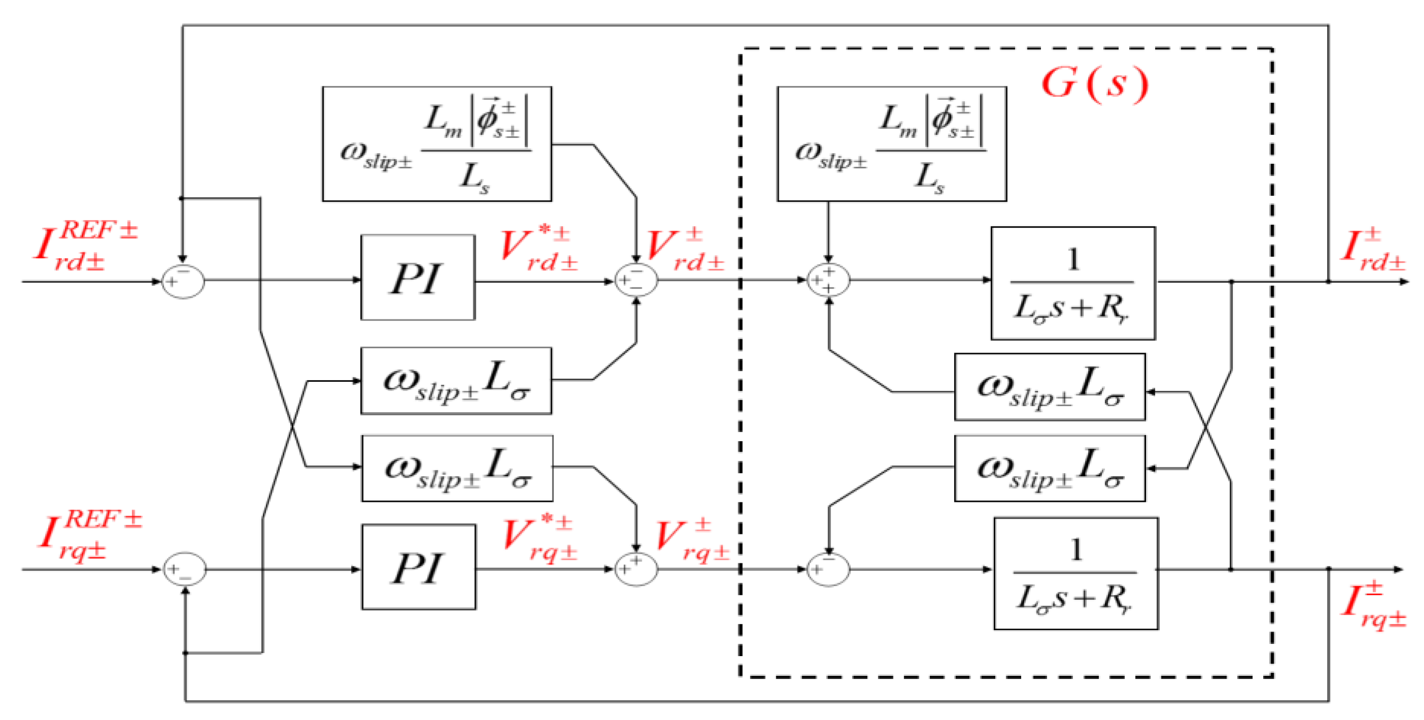
Equations (8)–(11) can then be used to design the proportional-integral (PI)-based vector controller for both positive and negative sequence rotor currents.
The actual rotor controller structure for DFIG normal operations with feed-forward decoupling is illustrated in
Figure 4.
4. Controller for DFIG Open Stator Operation under Unbalanced Grid Voltages
With the goal of smooth connection between the DFIG and the grid, the initial machine voltage at the open stator terminal needs to be exactly the same when compared to the grid voltage in terms of magnitude, frequency and phase.
The DFIG model derived previously should be adjusted according to its open stator dynamics, as the lack of stator excitation causes the machine to exhibit different electrical dynamics. With the absence of stator currents, (4)–(7) can be simplified as:
It can be observed from (12)–(15) that all the flux terms in the machine are directly produced by the rotor currents. Therefore, stator voltages can be induced initially by exciting the rotor windings. Using the same stator voltage orientation, the rotor voltage equations can be derived for the DFIG open stator condition as:
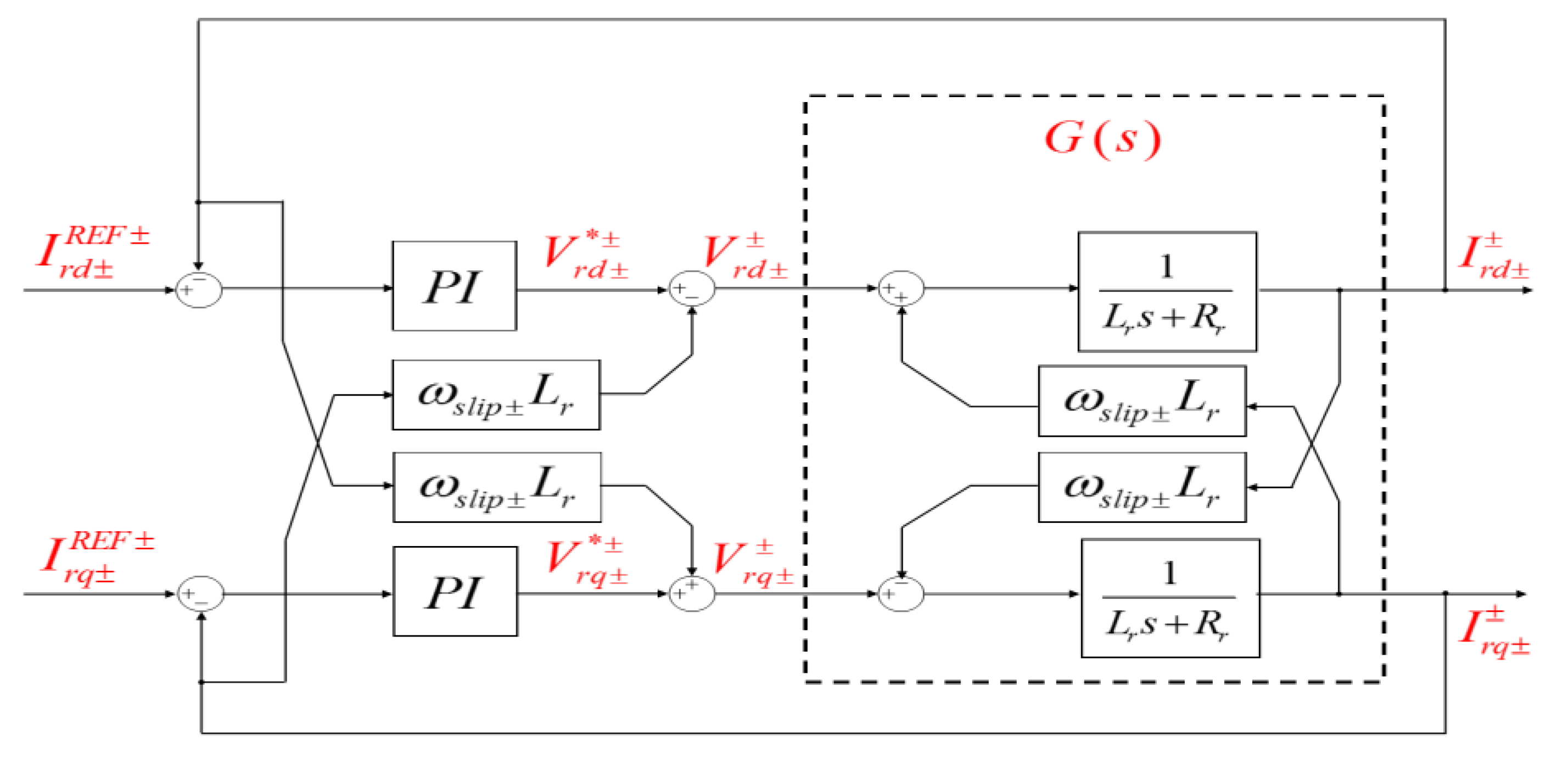
Equation (16) can then be used to design the open stator vector controller for both positive and negative sequence rotor currents. However, comparing (8)–(11) and (16)–(19), several controller differences exist for both operating conditions of the DFIG, which are:
The decoupling terms are different, where dominant back EMF influence does not exist in the open stator case.
The electrical time constant σ/Rr for DFIG normal operations changes to Lr/Rr when the stator is open. Since σ < Lr, the control loop dynamics for normal operation should be set faster than the open stator case.
The actual rotor controller structure for DFIG open stator operations with feed-forward decoupling is illustrated in
Figure 5.
5. Rotor Current Reference Setting During Unbalanced Grid Voltage Conditions
The stator flux
and rotor currents
in (12)–(15) can be expressed by their positive and negative sequence components using (2) and (3), resulting in the following expression:
Separating the constant and exponential terms in (20), the rotor current responsible for producing stator positive and negative sequence fluxes are determined as:
Similarly, the positive and negative sequence components of the induced stator voltage
in (12) can be expressed by using (2) and (3) below:
Equating on both sides of (23) results in the following open stator relationship between voltages and flux on the stator:
Substituting (24) into (21) and (22) and noting that
for stator voltage orientation, the rotor reference current can thus be expressed as:
Since the objective is to ensure that the induced stator voltage is synchronized to the grid voltage, the positive and negative sequence voltages in (25) must be directly obtained from the grid voltage
such that:
where
represents the grid voltage sequence components in both positive and negative synchronous reference frames. It was shown in various literature [
28,
29] that when the DFIG stator is connected to the grid, its active and reactive power outputs along with the oscillations caused by voltage unbalance can be expressed as:
where:
Substituting (24) and (25) into (29) and (28), respectively, it is worth noting that the rotor current settings stipulated in (25) lead to zero power exchange with the grid. This implies that after synchronization, the DFIG is connected to the grid at zero power leading to a smooth transition between open stator and normal operation control.
6. Implementation Procedure
This section briefly details several issues with respect to DFIG soft synchronization, where a step-by-step description of the proposed procedure is given for its proper implementation.
6.1. Incremental Encoder Angle Offset on Rotor Alignment
The rotor electrical angle measurement is fundamental for enabling rotor control in both normal and soft synchronization conditions. This information can be obtained by using an encoder coupled with the machine shaft that produces the rotor mechanical angular position. The incremental encoder is widely used for its lower cost compared to other technologies. Note this type of encoder only measures the relative position of the rotor with respect to an initial resting angle
. If the rotor is not initially aligned to the stator stationary axis, i.e.,
, then the actual rotor angle
θr will introduce an offset in the slip angle
which is used for rotor current transformation onto the synchronous frame. Since the initial induced stator voltage results from rotor current regulation, offset in
causes a phase shift between stator and grid voltage prior to synchronization. In [
20], a separate PLL is proposed for computing the stator voltage angle so as to converge it to the grid angle; whereas in [
23], a simple method is introduced where
is approximated and added to
. The approximation is given as:
where
is obtained from the grid-side PLL and
can be calculated as
. The rotor initial alignment does not pose as an issue for machines that use absolute encoders or sensorless control, such as in [
30].
6.2. Controller Gain Interchange between Normal Operation and Synchronization
As discussed previously, the changing rotor dynamics require changing controller gains, as well as feed-forward compensation terms depending on the mode of DFIG operation. So, it is important to consider that the transition between the controller structures depicted in
Figure 4 and
Figure 5 are neither too fast or too slow as either mode may negatively impact the smooth connection to the grid. To be precise, from the point of closing the grid contactors, the control voltages
and
should be forced to remain the same for a period that is equal to the contactor mechanical closing time. This operation can be described as:
where
k in (31) represents the current sampling instance and
n is a unit integer increment that resets to zero if the following condition is met:
where
and
represent the rotor current control sampling period and grid contactor mechanical closing time.
6.3. Complete Procedure for DFIG Soft Synchronization to Unbalanced Grid Voltages
Based on all aspects discussed in previous sections, as well as practical implementation issues mentioned in this section, a flow chart is provided in
Figure 6 that details all the initial actions required leading up to the point of synchronization.
It should be noted that the grid side control is included in
Figure 6 for completeness of the procedure; however, experimental work in the following section is carried out only for the machine side control. The DC bus is initially charged and regulated through grid synchronization process.
7. Experimentation
This section provides experimental results gathered for the soft synchronization of the DFIG to an unbalanced grid. Two test cases were implemented for comparison, with standard soft synchronization used in the first case and the proposed procedure used in the second case. The DFIG test rig used is rated at 2.2 kW which is, in turn, connected to a 380 V grid. For experimental investigations a real-time National Instruments controller with built-in DAQ/FPGA modules is used.
The laboratory setup is shown in
Figure 7 below.
The system parameters for the experimental DFIG are shown in
Table 1.
7.1. Soft Synchronization of the DFIG to an Unbalanced Grid Using Standard Procedure
The standard soft synchronization procedure detailed in [
16,
17,
18,
19,
20,
21,
22] was first carried out in order to connect the DFIG to the grid. Grid voltage unbalance was set so that each phase has the following deviation from the nominal voltage of 380 V; i.e., Phase A: 40%, Phase B: 20% and Phase C: 50%.
The DC link voltage was initially charged and stabilized through the grid side control, and the machine was driven to 20% slip by the DC drive shown in
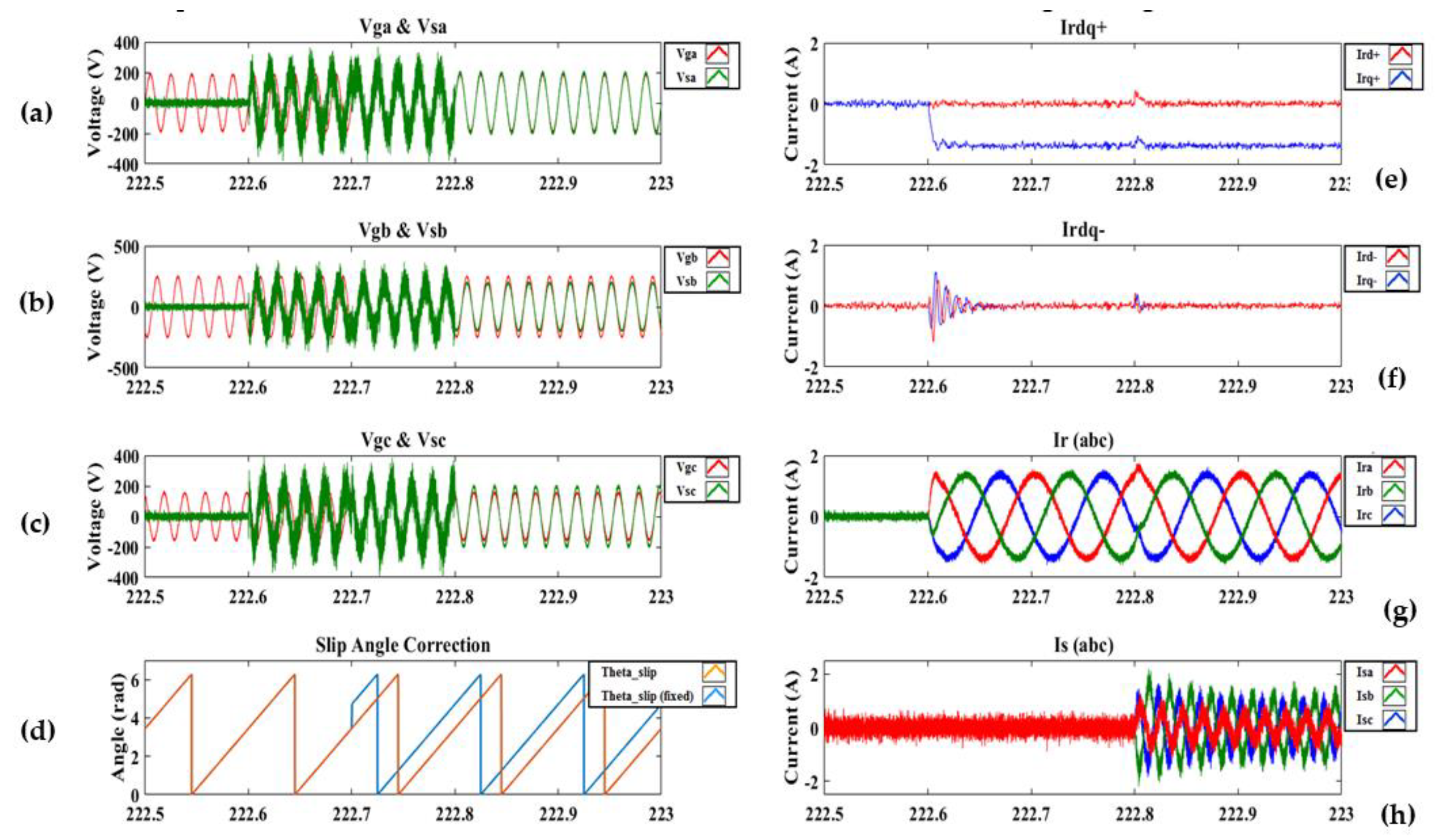
Figure 7. Once the initial setup had been completed, the synchronization was then performed. Experimental results for the standard synchronization are shown in
Figure 8.
Testing conditions as discussed in the previous section, which deliberately produces an unbalanced stator voltage equal to the The synchronization begins at
t = 222.6 s as the positive sequence rotor current
is controlled to enforce
. It should be noted that for the standard synchronization procedure, the negative sequence rotor current controller is disabled. Therefore
is not regulated throughout the synchronization process. Each synchronization step shown in
Figure 6 is programmed to be completed within 5 cycles of the fundamental grid frequency, which gives sufficient time for the rotor current controller to reach steady state operation.
The initial rotor angle offset can be observed in
Figure 8a, where the induced stator voltage is phase shifted from the grid voltage. This angle offset was fixed at
t = 222.7 s, which is shown in
Figure 8d. It can be noted from
Figure 8f that, since the negative sequence rotor current remained at zero, the 3-phase rotor current waveform is balanced and is shown in
Figure 8g.
7.2. Soft Synchronization of the DFIG to an Unbalanced Grid Using Proposed Procedure
The proposed soft synchronization procedure was carried out under the same unbalanced grid voltage. The experimental results for the proposed procedure are shown in
Figure 9.
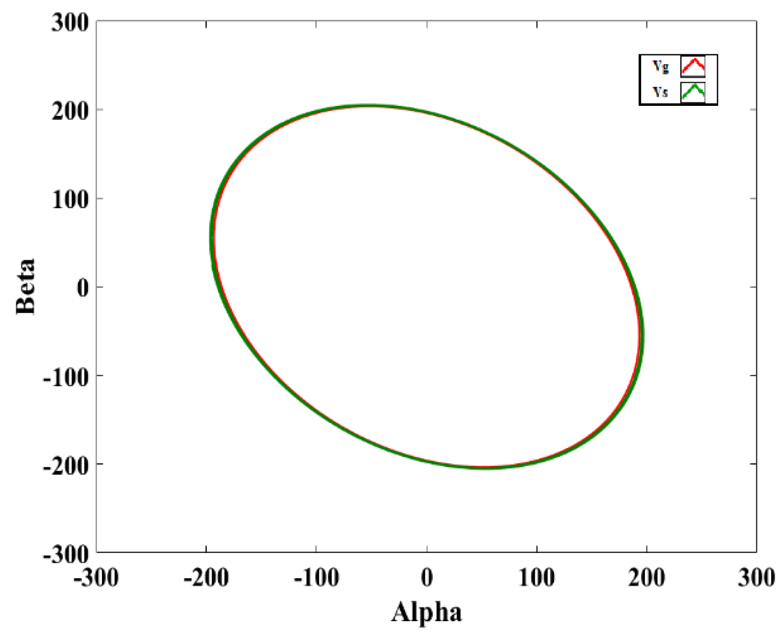
Compared to the standard procedure, the only difference is the introduced negative sequence rotor current controller. Furthermore, it can be seen from the results that both and are regulated according to the conditions stipulated in (25).
The induced stator voltage matches the grid voltage even during unbalance, which can be seen in the stationary reference frame shown in
Figure 10. The resulting stator current transient during synchronization can be seen to have minimal impact on the machine. The results observed clearly demonstrate that setting rotor negative sequence current in the synchronous frame, according to (25), causes the induced stator voltage to become as unbalanced as the grid voltage. This will then minimize the stator current transient impact during DFIG synchronization to the grid. Compared to the standard procedure, the proposed controller adds the additional feature which enables a smooth connection of the DFIG to unbalanced grid voltages.
8. Conclusions
A method for connecting a DFIG to unbalanced grid voltages is proposed in this paper. The procedure incorporates a negative sequence rotor current controller during DFIG open stator operation, which forces the initial induced stator voltage to be as unbalanced as the grid voltage—hence allowing a low impact synchronization with the grid. The proposed strategy has been validated on a 2.2 kW DFIG test rig. The experimental results show that the proposed control scheme effectively controls induced stator voltage, via rotor positive and negative sequence currents, to accurately follow the unbalanced grid voltage and hence avoids current and power impacts to both the DFIG and the grid at the time of connection.
Author Contributions
Conceptualization, A.K. and X.M.H.; methodology, A.K.; software, X.M.H.; validation, A.K. and X.M.H.; formal analysis, A.K. and X.M.H.; investigation, A.K. and X.M.H.; resources, M.A.K.; data curation, X.M.H.; writing—original draft preparation, A.K. and X.M.H.; writing—review and editing, A.K., X.M.H. and P.B.; visualization, P.B.; supervision, M.A.K.; project administration, M.A.K.; funding acquisition, M.A.K. and P.B. All authors have read and agreed to the published version of the manuscript.
Funding
The research was funded by the Department of Science and Innovation (DSI) of South Africa, as a part of Energy Research Programme.
Conflicts of Interest
The authors declare no conflict of interest.
References
- Nakra, H.; Dube, B. Slip power recovery induction generators for large vertical axis wind turbines. IEEE Trans. Energy Convers. 1988, 3, 733–737. [Google Scholar] [CrossRef]
- Pena, R.; Clare, J.; Asher, G. Doubly fed induction generator using back-to-back PWM converters and its application to variable-speed wind-energy generation. IEE Proc. Electr. Power Appl. 1996, 143, 231. [Google Scholar] [CrossRef]
- Petersson, A. Analysis, Modeling and Control of Doubly-Fed Induction Generators for Wind Turbines. Ph.D. Thesis, Chalmers University of Technology, Göteborg, Sweden, 2003. [Google Scholar]
- Hansen, A.D.; Iov, F.; Blaabjerg, F.; Hansen, L.H. Review of contemporary wind turbine concepts and their market penetration. Wind Eng. 2004, 28, 247–263. [Google Scholar] [CrossRef]
- Miller, A.; Muljadi, E.; Zinger, D. A variable speed wind turbine power control. IEEE Trans. Energy Convers. 1997, 12, 181–186. [Google Scholar] [CrossRef]
- Ekanayake, J.; Holdsworth, L.; Wu, X.; Jenkins, N. Dynamic modeling of doubly fed induction generator wind turbines. IEEE Trans. Power Syst. 2003, 18, 803–809. [Google Scholar] [CrossRef]
- Tapia, G.; Tapia, A.; Ostolaza, J.X. Two alternative modeling approaches for the evaluation of wind farm active and reactive power performances. IEEE Trans. Energy Convers. 2006, 21, 909–920. [Google Scholar] [CrossRef]
- Lei, Y.; Mullane, A.; Lightbody, G.; Yacamini, R. Modeling of the wind turbine with a doubly fed induction generator for grid integration studies. IEEE Trans. Energy Convers. 2006, 21, 257–264. [Google Scholar] [CrossRef]
- Lei, T. Doubly-Fed Induction Generator Wind Turbine Modelling, Control and Reliability. Ph.D. Thesis, University of Manchester, Manchester, UK, 2014. [Google Scholar]
- Xu, L.; Cartwright, P. Direct active and reactive power control of DFIG for wind energy generation. IEEE Trans. Energy Convers. 2006, 21, 750–758. [Google Scholar] [CrossRef]
- Liu, Z.; Mohammed, O.; Liu, S. A novel direct torque control of doubly-fed induction generator used for variable speed wind power generation. In Proceedings of the 2007 IEEE Power Engineering Society General Meeting, Tampa, FL, USA, 24–28 June 2007; pp. 1–6. [Google Scholar]
- Breban, S.; Radulescu, M.; Robyns, B. Direct active and reactive power control of variable-speed doubly-fed induction generator on micro-hydro energy conversion system. In Proceedings of the XIX International Conference on Electrical Machines—ICEM 2010, Rome, Italy, 6–8 September 2010; pp. 1–6. [Google Scholar]
- Cardenas, R.; Peña, R.; Proboste, J.; Asher, G.; Clare, J. Rotor current based MRAS observer for doubly-fed induction machines. Electron. Lett. 2004, 40, 769–770. [Google Scholar] [CrossRef]
- Zhi, D.; Xu, L.; Williams, B. Model-based predictive direct power control of doubly fed induction generators. IEEE Trans. Power Electron. 2009, 25, 341–351. [Google Scholar] [CrossRef]
- Elizondo, J.L.; Olloqui, A.; Rivera, M.; Macias, M.E.; Probst, O.; Micheloud, O.M.; Rodríguez, J. Model-based predictive rotor current control for grid synchronization of a DFIG driven by an indirect matrix converter. IEEE J. Emerg. Sel. Top. Power Electron. 2014, 2, 715–726. [Google Scholar] [CrossRef]
- Yuan, G.; Chai, J.; Li, Y. Vector control and sinchonization of doubly fed induction wind generator system. In Proceedings of the 4th International Power Electronics and Motion Control Conference—IPEMC 2004, Xi’an, China, 14–16 August 2004; pp. 886–890. [Google Scholar]
- Blaabjerg, F.; Teodorescu, R.; Liserre, M.; Timbus, A. Overview of control and grid synchronization for distributed power generation systems. IEEE Trans. Ind. Electron. 2006, 53, 1398–1409. [Google Scholar] [CrossRef]
- Lang, Y.; Zhang, X.; Xu, D.; Hadianamrei, S.R.; Hongfei, M. Stagewise control of connecting DFIG to the grid. IEEE Int. Symp. Ind. Electron. 2006, 2, 1129–1133. [Google Scholar]
- Iwanski, G.; Koczara, W. PLL grid synchronization of the standalone DFIG based wind turbine or rotary UPS. In Proceedings of the EUROCON 2007—The International Conference on “Computer as a Tool”, Warsaw, Poland, 9–12 September 2007; pp. 2550–2555. [Google Scholar]
- Cortajarena, J.A.; De Marcos, J.; Alvarez, P.; Vicandi, F.; Alkorta, P. Start up and control of a DFIG wind turbine test rig. In Proceedings of the IECON 2011—37th Annual Conference of the IEEE Industrial Electronics Society, Melbourne, VIC, Australia, 7–10 November 2011; pp. 2030–2035. [Google Scholar]
- Dal, M.; Şimşek, C.; Ceylan, M.C.; Akcil, L. Characterisation of DFIG controlled by back to back coverters: Simulation and hardware implementation. In Proceedings of the 16th International Power Electronics and Motion Control Conference and Exposition 2014, Antalya, Turkey, 21–24 September 2014; pp. 594–599. [Google Scholar]
- Tapia, G.; Santamaria, G.; Telleria, M.; Susperregui, A. Methodology for smooth connection of doubly fed induction generators to the grid. IEEE Trans. Energy Convers. 2009, 24, 959–971. [Google Scholar] [CrossRef]
- Zhan, L.; Jin, X.; Zhang, L. An improved grid synchronization control of doubly-fed induction generator. In Proceedings of the 2012 Asia-Pacific Power and Energy Engineering Conference, Shanghai, China, 27–29 March 2012; pp. 1–5. [Google Scholar]
- Chen, S.Z.; Cheung, N.C.; Zhang, Y.; Zhang, M.; Tang, X.M. Improved grid synchronization control of doubly fed induction generator under unbalanced grid voltage. IEEE Trans. Energy Convers. 2011, 26, 799–810. [Google Scholar] [CrossRef]
- Thakallapelli, A.; Kamalasadan, S.; Muttaqi, K.M.; Hagh, M.T. A synchronization control technique for soft connection of doubly fed induction generator based wind turbines to the power grids. IEEE Trans. Ind. Appl. 2019, 55, 5277–5288. [Google Scholar] [CrossRef]
- Nian, H.; Cheng, P.; Zhu, Z.Q. Coordinated direct power control of DFIG system without phase-locked loop under unbalanced grid voltage conditions. IEEE Trans. Power Electron. 2016, 31, 2905–2918. [Google Scholar] [CrossRef]
- Anderson, P.M. Analysis of Faulted Power Systems; IEEE Press: Piscataway, NJ, USA, 1995. [Google Scholar]
- Song, H.-S.; Nam, K. Dual current control scheme for PWM converter under unbalanced input voltage conditions. IEEE Trans. Ind. Electron. 1999, 46, 953–959. [Google Scholar] [CrossRef]
- Nasiri, M.; Mohammadi, R. Peak current limitation for grid side inverter by limited active power in PMSG-based wind turbines during different grid faults. IEEE Trans. Sustain. Energy 2017, 8, 3–12. [Google Scholar] [CrossRef]
- Cardenas, R.; Pena, R.; Proboste, J.; Asher, G.; Clare, J. MRAS observer for sensorless control of standalone doubly fed induction generators. IEEE Trans. Energy Convers. 2005, 20, 710–718. [Google Scholar] [CrossRef]
© 2020 by the authors. Licensee MDPI, Basel, Switzerland. This article is an open access article distributed under the terms and conditions of the Creative Commons Attribution (CC BY) license (http://creativecommons.org/licenses/by/4.0/).


